


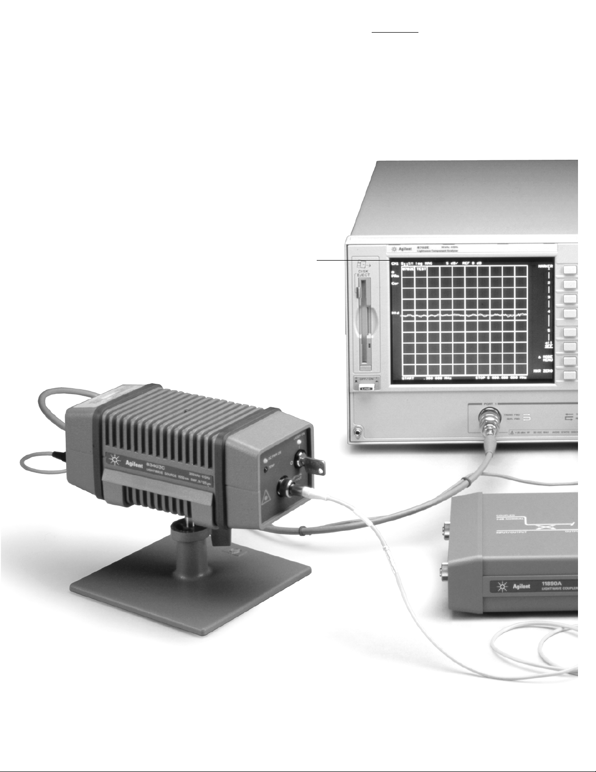
Agilent 8702E
Lightwave Component Analyzer
850 nm, 1300 nm, 1550 nm
300 kHz to 3 or 6 GHz
Product Overview
Accurate modulation frequency response measurements
of lightwave components
2
Measurement versatility by design
Lightwave coupler
For measuring
optical return loss
and locating discontinuities.
Agilent 11890A,
single-mode (9/125 um)
Lightwave source
A stable, calibrated laser source with
high modulation bandwidth and large dynamic range.
Agilent 83402C, 1300 nm, single-mode (9/125 µm), 300 kHz to 6 GHz, DFB
Agilent 83403C, 1550 nm, single-mode (9/125 µm), 300 kHz to 6 GHz, DFB
Guided measurements
Fast, easy measurements
without intensive training.

3
Electrical, optical, and electro-optical calibrations
Accurate, repeatable measurements of all the components of a fiber
optic system.
System
Provides access to limit testing, swept harmonic measurements
(option 8702E-002), time domain analysis, and other special functions.
Copy
Send measurement results to plotter or printer over the GPIB, parallel,
or serial interface.
Save/Recall
Save and recall test sequences, measured data, calibration data, and
instrument states internally or with the built-in disk drive.
Sequencing
Internally configure and automate measurements with test
sequencing, an enhanced form of keystroke recording.
Versatile configuration
Integrated S-parameter test set provides complete forward and
reverse measurements in 50 ohms or 75 ohms (with option
8702E-075). For flexibility in test set configuration, you can delete the
built-in test set (with option 8702E-011) and select your own test set
(compatible with Agilent 85046A and 85047A.)
Lightwave receiver
Calibrated, high modulation
bandwidth, photodiode receiver.
Agilent 83410C, 1300 and 1550 nm, SMF and MMF, 300 kHz to 3 GHz, amplified
Agilent 83411C, 1300 and 1550 nm, SMF, 300 kHz to 6 GHz
Agilent 83411D, 1300 and 1550 nm, SMF, 300 kHz to 6 GHz, amplified
Agilent 83412B, 850 nm, SMF and MMF, 300 kHz to 3 GHz, amplified
Internal synthesized
RF source
Provides accurate
modulation frequencies,
sweeping 300 kHz
to 3 GHz and optionally
6 GHz (option 8702E-006).

4
Measurements across the system
Modern lightwave transmission systems require accurate and repeatable characterization of their electrooptical, optical, and electrical components to guarantee high-speed performance. The Agilent 8702E lightwave component analyzer improves the design and specification of these lightwave components.
It operates by analyzing a swept frequency signal modulating a 1300 or 1550 nm optical carrier.
With the capabilities of the Agilent 8702E you can:
■
Characterize component bandwidths with modulation frequencies to 3 GHz (6 GHz optionally).
■
Isolate laser and photodiode response with calibrated transmitter and receiver measurements.
■
Accurately measure electrical return loss of photodiodes, lasers, connectors, and other lightwave components.
■
Measure the swept frequency response of modulation second and third harmonics.
■
Locate reflections and view step response with distance/time domain measurements.
System Operation
The 8702E consists of an RF
source that provides a known
swept, synthesized modulation
signal, and a receiver that
measures the magnitude and
phase of the returned RF signal.
To measure a lightwave device,
the RF source of the 8702E
provides a modulation signal to an
external lightwave source, which
provides a modulated light signal
to the optical device. An external
lightwave receiver module demodulates the lightwave signal after it
passes through the optical device
under test. The demodulated RF
signal is passed to the receiver of
the 8702E where the magnitude
and phase response of the signal
is measured. With this system,
the transfer function of the test
device is determined as a function
of modulation frequency.
Often the limiting elements in a
fiber optic transmission system
are the electro-optical components (e.g. lasers, APDs, PIN
photodiodes, and, modulators)
which convert the electrical
information to optical or vice
versa. With the 8702E, calibrated
measurements of modulation
bandwidth, responsivity, and
modulation range of an individual transducer are possible.
Electro-optical components
Electrical components
Optical components
Optical components such as fiber,
connectors, splitters, couplers,
and lenses make up much of a
fiber optic network. The 8702E
measures the modulation bandwidth, insertion loss, length and
optical return loss of these
components. Reflections can be
located and the step response of
a component viewed with the
time domain feature.
Linear electrical components
such as amplifiers, filters, and
transmission lines are used in
fiber optic systems. They also
require characterization to ensure
optimal performance. Typically
the bandwidth, insertion loss/
gain, insertion phase, impedance,
match and group delay are
required measurements.
Demodulated
Result
Modulated
Light
RF
In
Optical
Device
RF
Out
 Loading...