

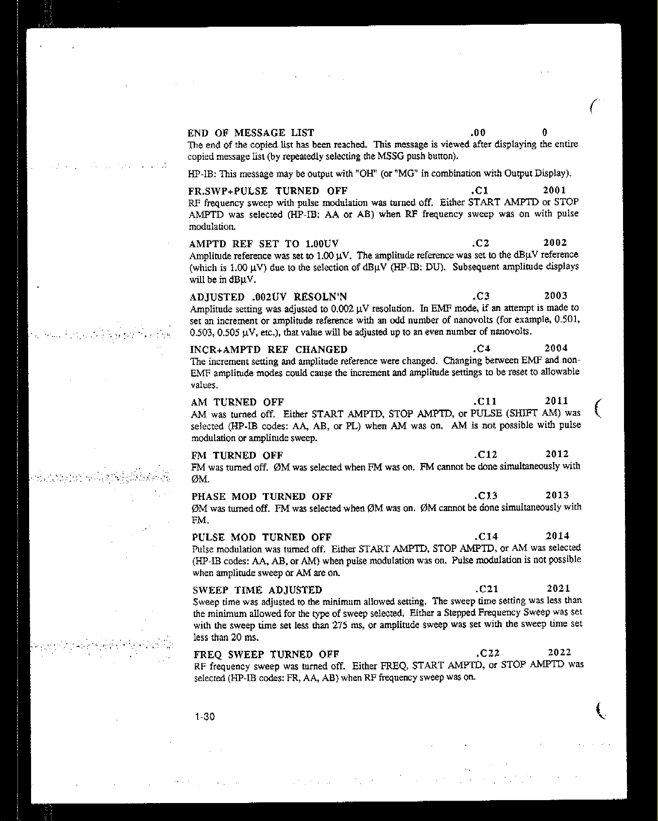
TECHNICAL MANUAL
OPERATOR’S, ORGANIZATIONAL, DIRECT
SUPPORT, AND GENERAL SUPPORT
I’
MAINTENANCE MANUAL
SIGNAL GENERATOR SG-1207/U
(HEWLETT-PACKARD MODEL 8642M)
‘“/, */ ’ -, ,,d>
(NSN 6625-01-233-8615) r”:‘:‘s :I,,:

COPYRIGHT AND DISCLAIMER NOTICE
Copyright - Agilent Technologies, Inc. Reproduced with the permission of Agilent
Technologies Inc. Agilent Technologies, Inc. makes no warranty of any kind with regard
to this material including, but not limited to, the implied warranties of merchantability
and fitness for a particular purpose. Agilent Technologies, Inc. is not liable for errors
contained herein or for incidental or consequential damages in connection with the
furnishing, performance, or use of this material or data.
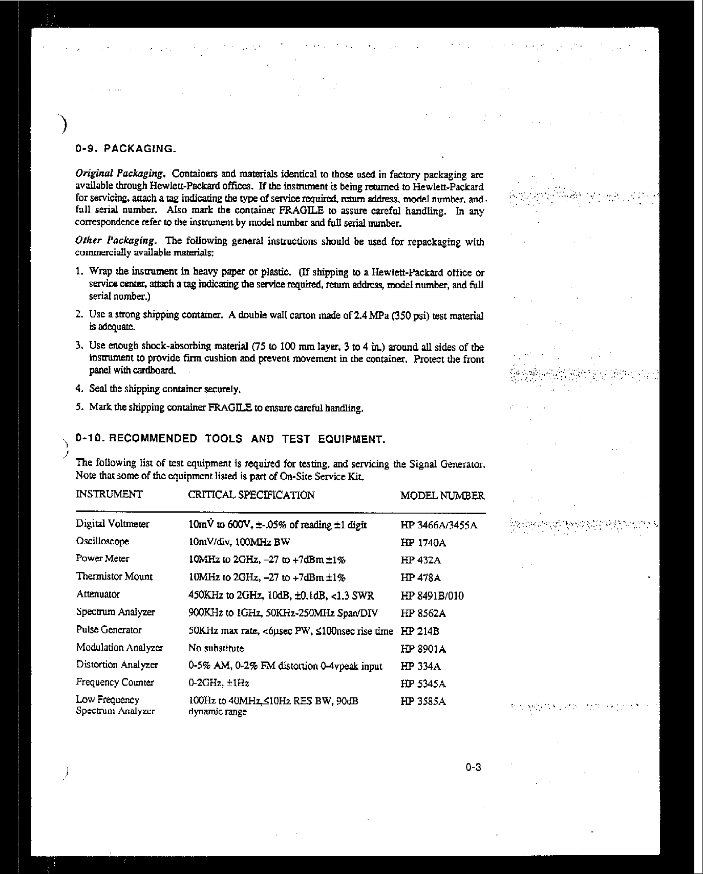
O-9. PACKAGING.
Original Puckuging. Containers and materials identical m rhose used in facmry packaging arc
available through Hewlett-Packard offices. If the insuument is being rammed m Hewlett-Packard
for servicing, attach a tag indicating the rype of service required, return address, mcdel number, and.
full serial number. Also mark the container FRAGILE m assure careful handling. In any
correspondence refer to the insmment by model number and full serial number.
Other PacKaging.
The following general insmxtions should be used for repackaging with
commercially available mat&&:
I. Wrap the insuument in heavy paper or plastic. (If shipping m a Hewlett-Packard office or
sen4ce center, attach a tag indictig the service rqulr-ed m xlckss, mcdd
number,
and full
serial number.)
2. Use a strong shipping container. A double wall carton made of 2.4 MPa (350 psi) test material
is aaequate.
3. Use enough shock-absorbing material (75 m 100 mm layer, 3 m 4 in.) around all sides of the
insuument m provide Frm cushion and prevent movement in dx container. Protect the front
panel withcardboard.
4. Seal the shipping container securely.
5. Mark the shipping container FRAGILE m ensure careful handling.
‘, O-10. RECOMMENDED TOOLS AND TEST EQUIPMENT.
The following list of test equipment is required for testing,
Note that some of the equipment listed is part
INSTRuMENT
Digital Voltmeter
Oscilloscope
Power Meter
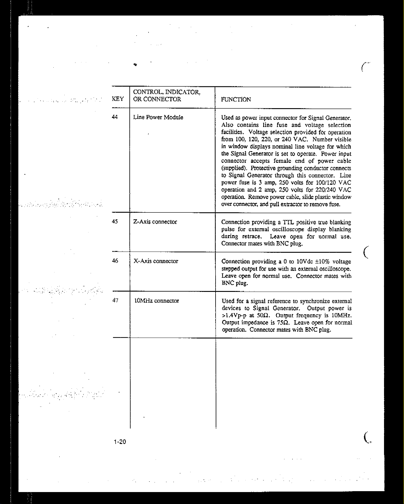
Thermistor Mount
Attenuator
Specuum Analyzer
Pulse Generator
Modulation Analyze1
Distortion Analyzer
Frequency Counter
Low Frequency
Spccmm Analyzer
CRITICAL SP!3X=ICATION MODUNLTMBEU
1CmV m 6OOV, i-.05% of reading fl digit
lOmV/div, loOMHa BW
1OMHz m 2GHz. -21 m +7dBmfl%
1OMHz to 2GH.z. -21 m +7dBm fl%
45OKHz m 2GHz,
9OOKHir to lGHz, 5OKHz-25OMHz
5OKHz max rare, <6psec PW,
No substitute
O-5% AM, O-246 FM distonion WvpeaL input
02CHz, +lHz
IC’OHz m40MH~<10H2 RES
dynamic range
of
On-Site Service K~L
lCdB, M.1d.B. cl.3 SWR
and
servicing tie Signal Generamr.
Span/DIV
<lOOnsec rise time
BW,
9OdB
Hp 3466.413455~
m 1740A
HP 432A
HP 478A
Hf’8491B/OlO
m 8562~
HP 214B
HP 8901A
HP 334A
HP 5345A
HP 3585A
‘~
:;. :, ,, ,, ,,,
I. ,, ,,,.’ .;. :,. ,,,,. ,,,

O-1 0. RECOMMENDED TOOLS AND TEST EQUIPMENT-Continued.
,, _, ,,,“..
INSTRUMENT
CRITICAL SPEtIFICATlON MODEL NUMBER
BNCtotypeN
BNC to dual banaua
SOn BNC-BNC (2 each)
BD ASSY PS TEST CONN
Flat
Long
Short
MSMCto&)SMC(4)
(F) BNC to (R SMC (2)
MSMCTEE
OSMAfo(f)SMC(2)
50 Pin Test Connector
16 Pin Test Connector
26 Pi Test Connector
HPO8642-80053
HP 0864240959
Hl'O8662-6UO7S
HPO8662-60080
Hp12SO-0827
HP12SO-0832
HpnSO-0837
HP12SO-1697
HP12Sl-5653
HP 1251-8105
HP 1251.8248
o-4
34PinTesrConnector
20PinTeestConnector
14 Fin.Test Connector
10 Pin Test Comwtor
Binding Post
HP 1250-8601.
HP12.51-8812
HP1251-8823
w 1252-0153
HP 5021-0844
HP 34118A
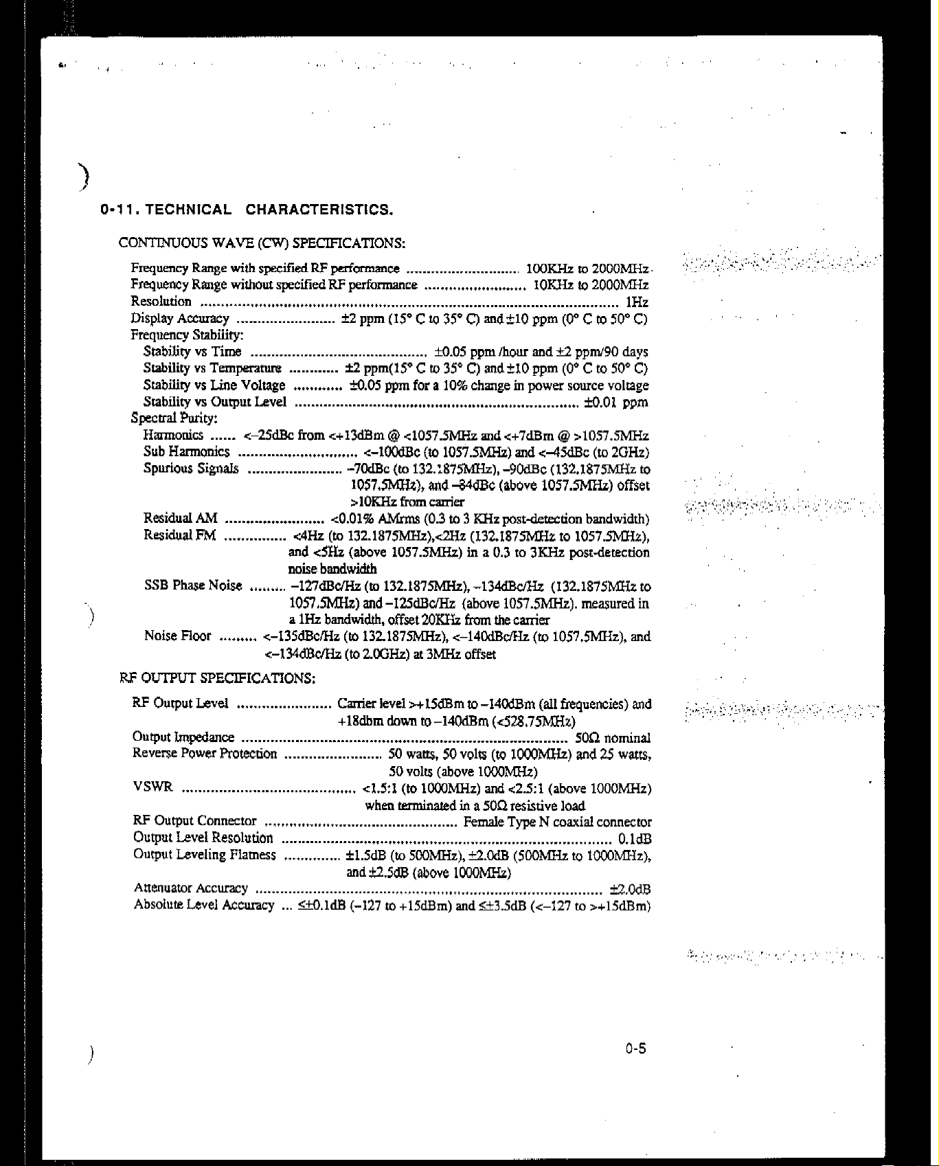
O-l 1. TECHNICAL CHARACTERISTICS.
II
CONTRiUOUS WAVE (CW) SPECIFICATIONS:
Frequency Range with specified RF performance . . . . . . . . . . . . . . . . . . . . . . . . . . 100KHz to 2OOOMHz.
Frequency
Resolution
Display Accuracy .____................... ic2 ppm (IS’ C to 35’ CJ
Frequency Smbility:
Stability
Stabiliry vs Temperaruff
Stability vs Line Voltage . . . . . . . . . . . .
Stabiliv
spectral Purity:
Hmonics
Sub Harmonics
Spurious Signals .._...._....._......... -7OdBc (10 132.:875MHz), -9OdBc (132.187mz to
Residual
Residual FM .._...._.._.... -z4Hz (to 132.1875MHz),~Wz (132.1875MXz to 1057.5MIz),
SSB Phase Noise
Noise Floor . . . . . . . . . <-135dBclMz (to 1321875MHz). <-14CklBcMz (to 1057.5MHt),
Range without specified RF performance . . . . . . . . . . . . . . . . . . . . . . . . .
.._ ._...._.................................. _ _...._..._.__........................................... 1Hz
xndk10 ppm (0” C to 50” C)
vs Time . . .._.._....._............................. M.05 ppm /how and +2 ppm/PO days
. . . . . .._.__. f2 ppm(lS’ C to 35’ C) and?10 ppm (0” C to SO” C)
X1.05
ppm for a 10% change in power source voltage
vs Output Level . . . . . .._......._..._.. _ . . . . . . . . . . . . . . . . . . . . . . . . . . . . . . . . . . . . . . . . . . . . . . M.O1 ppm
. . . . . . <-25dBc from <+13&m @ <1057.5MHz and<+7dBm @ >1057.5MHz
. . . . . . . . . . . . . . . . . . . . . . . . . . . . . +lCOdBc (to 1057.5MHz) and <45dBc (to 2GHz)
1057.!MIz), and -WcIBc (above 1057.5MHz) offset
rlOKHzkImcauier
AM . . . . . . _._ . . . . . . . . . . . . . . . ~0.01% &Inns (0.3 to 3 KHz post&t&ion bandwidth)
and &Hz (above 1057.5MHz) in a 0.3 to 3KHz
noise bandwidth
. . . . . . . . .
-127dBBe/Hz (m 132.1875MHz). -134dBu’Hz (132.1875MIIr to
1057.5hfHz) and -125clBc/Hz (above 1057SMHz). measured in
a 1I-k bandwidth, offset 2OKIL from the carrier
<-134wdBc/Hz (to ZOGHZ) at 3hfHz offset
IOK& to 2000MYHt
postdetection
and
‘,‘, ,,,. ,,,,,,.t,. ,,,., :‘<,,:,‘,,:.G .;‘:: ,” .,
RF OUTPUT SPECIFICATIONS:
RF Output Level
Output Impedance . . . . . . . . . . . . . . . . . . . . . . . . . . . . . . . . . . . . . . . . . . . . . . . . . . . . . . . . . . . . . . . . . . . . . . . . . . . . . . .
Reverse Power Protection
VSWR . . . . . . . . . . . . . . . . . . . . . . . . . . . . . . . . . . . . . . . . . . ~1.5~1 (to 1MxIMHz) and <2.5:1 (above 1OOOMHz)
RF Output Connector . . . . . . . . . .._......._........................... Female
Output Level
Output Leveling Flamess +.............
Attenuamr Accuracy tt.t....................................... _ .t...t....._l_....l..................... iz.OdB
Absolute Level Accuracy .
. . . . . . . . . . . . . . . . . . . . . . . Carrier level s++15dBm
+lEdbm down to -14OdBm (-z52&75’MHz)
. . . . . . . . . . . . . . . . . . . . SO waas, 50 volts (to IOOOMHt) and 25 watts,
SO volrs (above 1CCOMH.z)
when terminated in a 5O!Z resixive load
Resolution . . . . . . . . . . . . . _ . . . . . . . . . . . . . . . . . . . . . . . . . . . . . . . . . . . . . . . . . . . . . . . . . . . . . . . . . . . . . O.ldB
fl.SdB (to SOOhlHz), Yz.&lB (5cOMxz to loooM!IZ),
and ?2,5dE (above 1KJOMHz)
ti.ldB (-127 to +lSdBm) and e3.5dB (r-127 to >+15dBm)
to-M-m (all frequencies) and
5061 nominal
Type N coaxial connector
o-5
:. \‘; .,:,! ,,*:. .,,. 1 ,.,,::; ,,, ; ,,,, ;.,., :,,jI ,_., :,,: ,,,.:, :: i.’
:.,:I; “.‘,... :,, ..,,
.,
.,,
:‘:I. ‘.“.
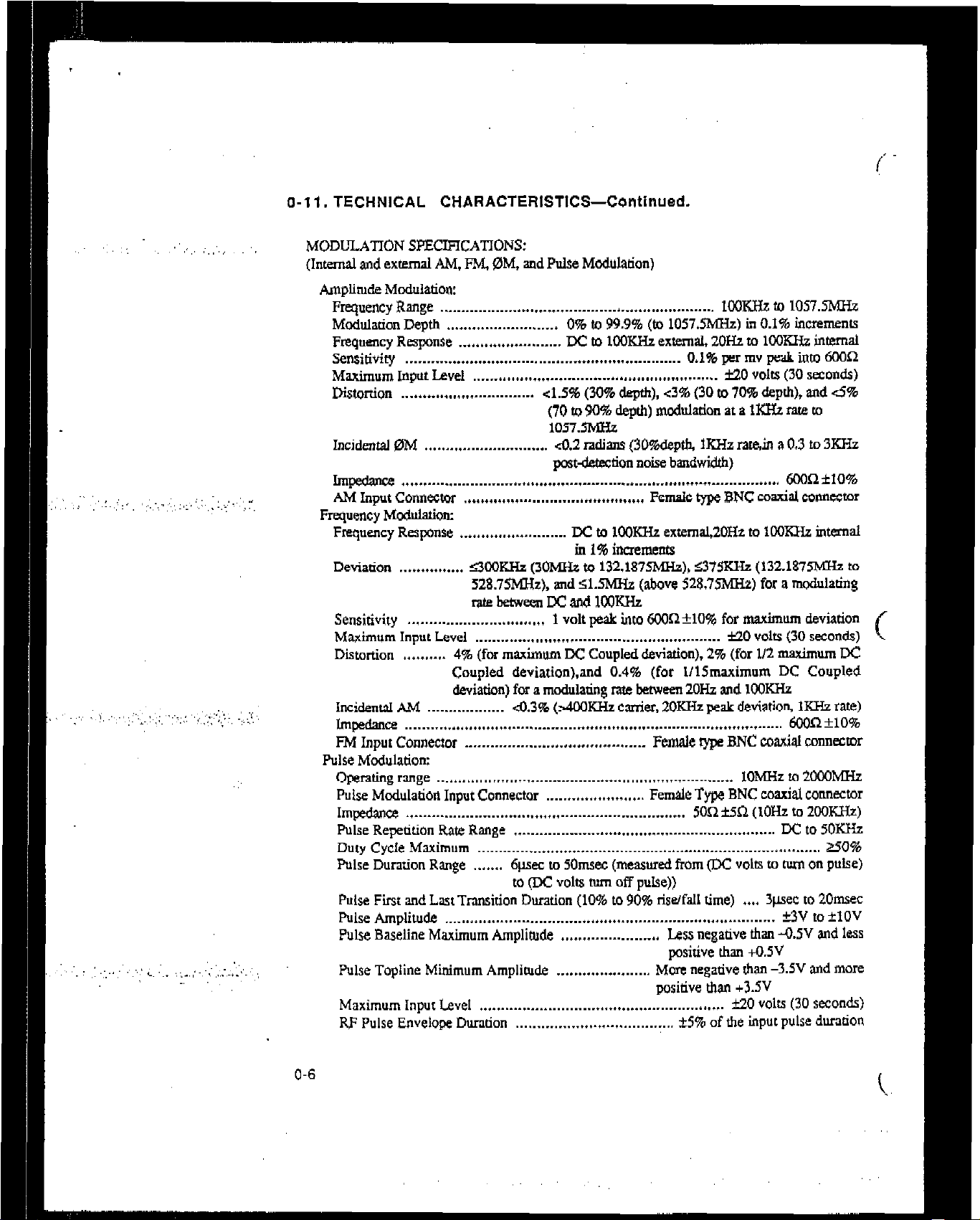
o-l I. TECHNICAL CHARACTERISTICS-Continueds
,‘., ,’
,,:,y: .,: .‘,,,: :‘,,
,, L. ‘,,, ;:..,‘-,‘~::.~,.-,I.~~~. ,‘,,:
MODULAl’ION SPECIFICATIONS:
(Inted and external AM, FM. @M, and Pulse Mcdulation)
Amplintde Modulation:
Frequency Range ................................................................ IOXHz to 1057.5MH.z
Mcddation Depth ..........................
Frequency Respnse ........................
Sensitivity
................................................................
Maximum Input Level ......................................................... ti0 volU (30
0% to 99.9% (to 1057.5was) ill 0.1% increments
EC to 1cOKHz external, ZOHZ to 1OoKHz imernal
0.1% per mv peak into 6OOR
seconds)
Distottion ............................... ~1.5% (30% depth), <3% (30 to 70% depth), and 6%
(70 to 90% depth) nlodltIation at a lKH2 rate to
1057.5hxHz
Incklental OM .............................
dY.2 radians (3o%depdl, IKHZ rat&n a 0.3 to 3KHz
postbtion noise bandwidth)
Impedance
........................................................................................
6ooILflO%
AM Input Connector .......................................... Female type BNC coaxial co~mwor
Fruquency
Moddation:
Frequency Response ......................... Jx to 1oom extemal,2OHz to 1cOKHz internal
in 1% inaements
Deviation ............... S3oOKHz (3oMHz to 132.1875MHz), ~375KHz (132.1875MXh to
528.75MHt), and zX?MHz (above 528.75MHz) for a modulating
l-akb@tweenDcand1M3KI”Iz
Sensitivity ................................
1 volt peak into 6OOn+lO% for maximum deviation
Maximum Input Level ......................................................... ti0 volts (30 seconds)
Distortion ..........
4% (for maximum DC Coupled deviation), 2% (for l/2 maximum DC
Coupled cleviation).and 0.4% (for IllSmaximum DC Coupled
deviation) for a mod&&g rate between 2OHz and IOOKHz
IncidentsJ AM .................. 4.3% (z4OOKHz wrier, 2OKHz peak deviation, KHz rate)
Impedance ........................................................................................ MX)RflO%
FM Input Connector .......................................... Female type BNC coaxial connector
Pulse Modulation:
Operating rmge ..................................................................... 1oMRz to 2OcGMHz
Pulse
Modulation
Input Connector ....................... Female Type BNC coaxial connector
Imp&we ................................................................. 5OR k.5l2 (IOH to ZOOKHZ)
Pulse Repetition Rate Range ............................................................. IX to 5OKHz
Duty Cycle Maximum ................................................................................ Z50%
Pulse Duration Rage .......
6p.w to 5Omsec (measured from (DC volts to turn on pulse)
to (DC volts two off pulse))
Pulse Fit and Last Transition Duration (10% to 90% ris~fall time) .... ~&XC to 2Omsec
Pulse Amplitude ............................................................................. *3V to flOV
Pulse Baseline Maximum Amplitude ....................... Less negative than -0.5V and less
positive than +0.5V
Pulse Topline Minimum Amphde ......................
More negative than -3.5V and more
positive than +3.5V
Maximum Input Level ......................................................... k20
RF Pulse Envelop Duration .....................................
zk5% of the input pulse duration
volts
(30
SKOW
O-6

)
O-l I. TECHNICAL CHARACTERISTICS-Continued.
MODULATION SPECIFICATTCNS-Continuecb
Pulse Mcdula!k~ontinue~
RF Fuke Envelope FirsVLast Transition Duration (lo%-SO% t&fall time) .... <0.5pec
RF Pulse Envelope OvershootUndershoot ..... 40% of the RF pulse envelope amplimde
RF Puke Envelope fit and Last Settling Duration
RF Pulse Envelope On/Off Rado .............................. . ...
Phase Mcxhtlation:
Maximum Deviation
Bandwidth ............ DC to 1SRH.z external (DC coupled) and 2OHx to 15RHz intemaI and
Resolution ...... 0.7% of setting or O.OOW% of maximum deviation, whichever is greater
Accuracy ............................................... *(5% of setting +O.W radians) at KHz rate
Distortion .............................................................................. ~0.4% at 1RHz rate
External Sensitivity
Maximum Input Level ......................................................... f15 volts (30 s~onda)
................................................................. s0RrSR(10Hzto2o3KHz)
0M Input Connector .......................................... Female type BNC coaxial connector
Internal Modularion OsciIlatw
Frequency Range: ........................................................................ 2OHz M loOK&
Frequency Rcaolutlon: ...................................................................... 1% of setting
Frequency Accuracy: ............ . . .............. . .................................. . ..... . ... 2% of setting
Output Level Range: .................................................... 0 to 3 volu peak inro 6OOR
Output Level Resolution: ............... . ............................................................. 4mv
Outptt Level Accuracy (within 1 set)! .... . ........................................... *(4%+15mV)
Distortion (zO.SV peah): .... co.0296 (20Hzm 15.8KHz ). -3.15% (15.8KHz to 1OORHa)
output Impedance: ........... . ......................................................................... 6ooR
Output Connector .............................................. Female type BNC coaxial connector
......
100 radians (from 1OORHa to 1321875MHz). 25 radians (from
132.187SMHz to 264.375MHz). 50 radians (from
2E4+375MUzto528.75MH.z), IWradims(fiom 528.75hC-h
to 1057.5MHz), 200 radians (from 1057.5MHz to 2.OCI-Ia)
external (AC coupled)
................................
1 volt pk for selected peak phase deviation
........
clpssec to within fl% of Illal
value (measured from two
90% pim)
W (1OMHz to 2OOOMHa)
REAR PANEL CONNECTOR SPECIFICATIONS:
Interface Connecmr:
Type ............ ANSI I IEEE Standard 488-1978 interface with SHI, AHl, Tl, 2 5, or 6,
Ll, 2, 3, or 4, SRl, RLl, PPO, DCI, ETO, and CO functions
implemented
Control .................. AI1 front panel functions, except power switch and increment Inob,
may be controlled through the interface
X-Axis Connector ......................................................................
Z-Axis Connectar ................ TTL posidve nue for CRT display blanking during reuace
External Reference Input ................... 1.2.5 or lOMHa, G5ppm, >0.5Vp-p 5OX2 input
1OMHz Output ........................... lOMHt, >lAVp-p into 50R, 750 impedance output
.i
I
GlOVdc, 50%
o-7
: :..,
O-l 1. TECHNICAL CHARACTERISTICS-Continued.
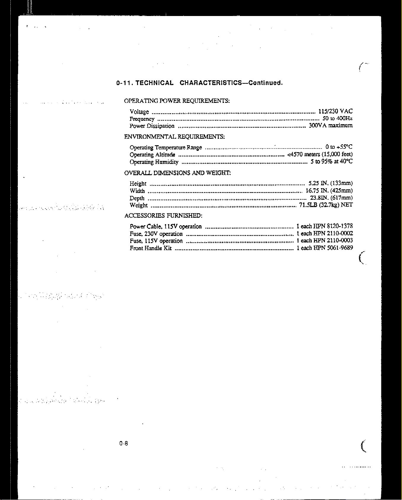
OPERATING POWER REQUIREMENTS:
Voltage ................... ......................................................................... 1151230 VAC
Frequency
Power Dissipation
...........................................................................................
........................................................................ 3WVA maximum
50 to 400Hz
ENVIRONMENTALREQUREMENT~
Operating Tempxuure Range ....................................... . .......................... 0 to +55’C
operathlg Attitude ............................................................
Operating Humidity .......................................................................
<4570 meters (15,wu feet)
5 to 95% at 4pC
OVERALL DIMENSIONS AND WEIGFIT:
Height ....................................................................................... 5.25 IN. (133m)
Width ....................................................................................... 16.75 IN. (425mm)
Depth .........................................................................................
Weight ..................................................................................
23.8IN. (617m)
71.5LB (32.7kg) NET
ACCESSORIES FURNISHED:
Power Cable, IISV option .................................................. 1 each HFN 8120-1378
Fusp 230V operation .............................................................
1 each H?N 211OaoOZ
Fuse, t15V operation ............................................................. 1 each HFN 2110-0003
Front Handle Kit ...................................................................
1 each HFN X61-9689
O-8
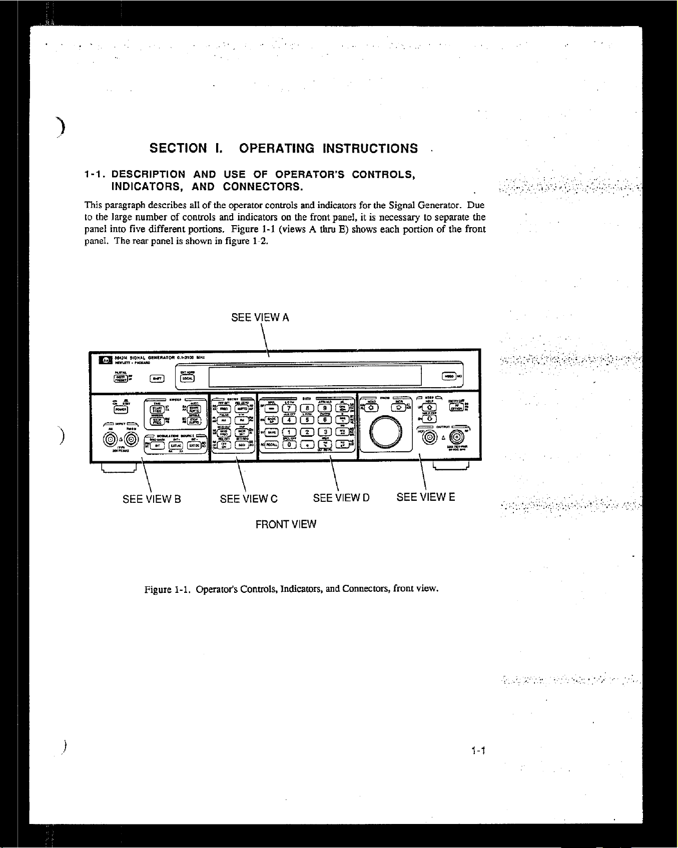
SECTION 1. OPERATING INSTRUCTIONS .
l-l. DESCRIPTION AND USE OF OPERATOR’S CONTROLS,
INDICATORS, AND CONNECTORS.
This paragraph describes all of the operator controls and indicators for the Signal Generator. Due
to the large number of controls and indicators on the front panef, it is necessary to sepruate the
panel into five different tmrtions. Figure l-l (views A thm E) shows each Dortion of the front
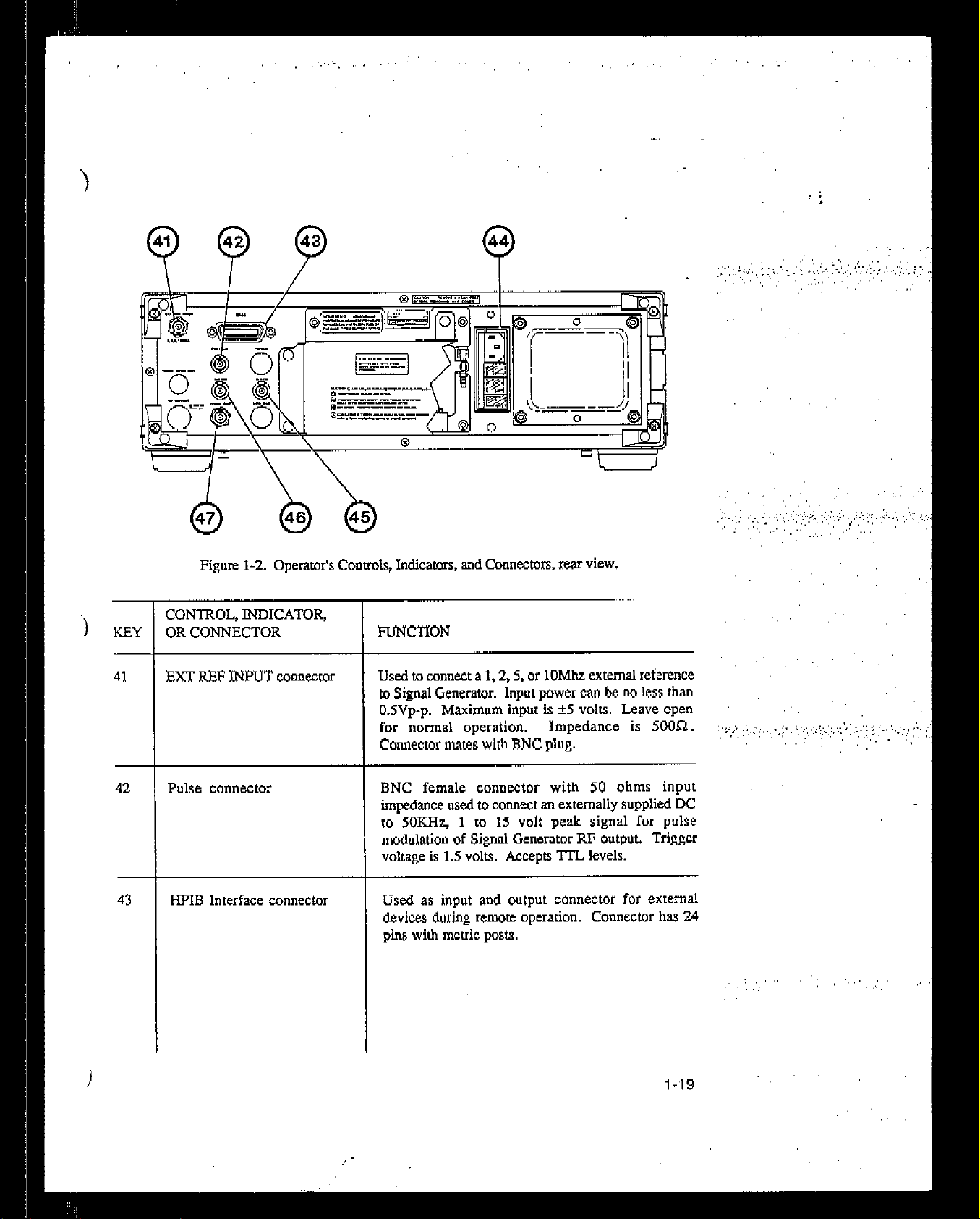
baneI. The rear panel is shown in figure 1-2.
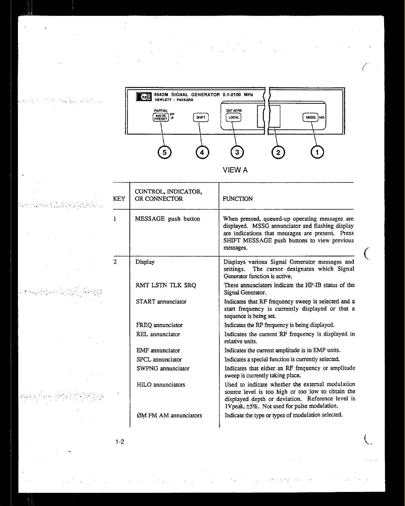
SEE VIEW A
-\
SEE VIEW 0
\
SEE VIEW C
FRONT VIEW
Figure l-l. Operator’s Controls, Indicators, and Connectors, front view.
\
SEE VIEW D
\’
SEE VIEW E
+
l-f


 Loading...