

Measuring High Power Waveforms
with the Agilent 86100A Digital
Communications Analyzer and the
86101A or 86103A Reference Receiver
Product Note 86100-2
2
The Agilent 86100A Digital Communications Analyzer (DCA) with
the 86101A/103A plug-in module is designed to perform Gigabit
Ethernet and Fibre Channel compliance testing. The Agilent
86101A has a built-in optical receiver to allow direct measurements
of transmitters operating in the 750 to 860 nm range and the
Agilent 86103A measures transmitters with operating wavelengths
from 980 to 1625 nm. These receivers have been designed to test
both low and high power signals. However, there are certain cases
where signal powers cause an overload/saturation situation in the
instrument which can lead to inaccurate results. This document is
intended to identify these conditions and present methods to ensure
valid measurement results. Since current commercial transceivers
tend to have more overshoot and ringing in the 750 to 860 nm
wavelengths, this paper will focus on the 86101A. However all of the
principles and techniques are equally applicable to the 86103A.
The Agilent 86100A wide-bandwidth digitizing oscilloscope has
built-in capabilities to perform measurements on high-speed digital
communications components and systems. The oscilloscope mainframe
accommodates one or two plug-in modules that are designed for
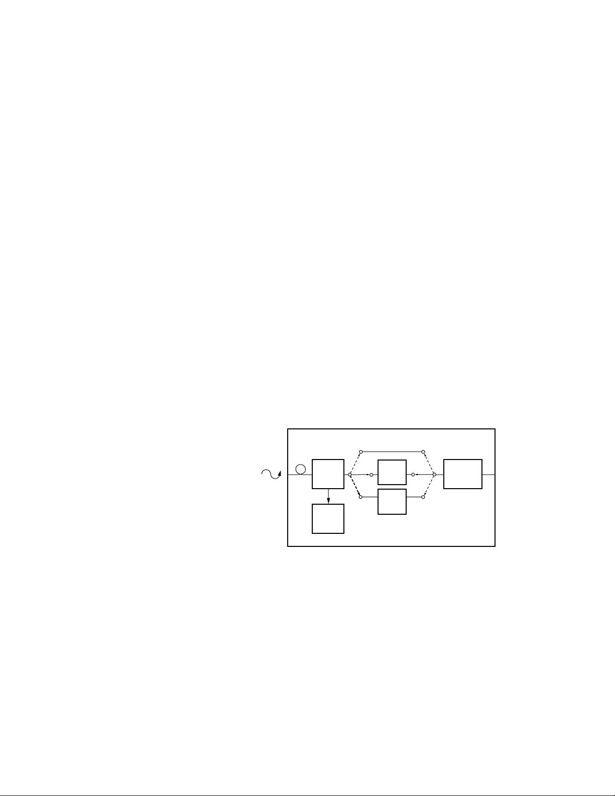
different types of signals. The Agilent 86101A plug-in module has
an electrical channel, an integrated optical receiver channel, and a
built-in average power meter. The optical receiver includes an amplified
photodiode (transimpedance amplifier) and dual switchable filters.
Figure 1. Agilent 86101A/103A block diagram
Eye-diagram tests are performed through a filtered bandwidth to
determine compliance to Gigabit Ethernet standards. The bandwidth
of the oscilloscope, including the optical receiver, is controlled to
meet a specific frequency response. This response is carefully
defined to have a fourth-order Bessel-Thomson response with the
filter’s 3 dB bandwidth being 75% of the data rate. For Gigabit
Ethernet (1.25 Gb/s) this frequency is 938 MHz. The specified
Bessel-Thomson filter provides measurement consistency between
different test systems. Without the use of Bessel-Thomson filters,
transceiver measurements and compliance test results could vary
depending upon the bandwidth and frequency response of the test
system being used.
Introduction
The Agilent 86100A/86101A
measurement configuration
Eye-diagram compliance
testing
Agilent 86101A/103A Optical Receiver
Amplified
Optical
Receiver
Average
Power
Monitor
Fibre
Channel
Filter
Gbit
Ethernet
Filter
Sampling/
Amplification

3
For example, high-speed lasers often exhibit significant overshoot
and ringing. This ringing is a high-frequency effect that can only be
observed when the oscilloscope system has a wide bandwidth. The
overshoot usually does not impact communication system performance
because system receivers have just enough bandwidth for an optimum
Bit Error Ratio (BER) and do not respond to these higher frequencies.
The unfiltered waveform resulting from this overshoot generally
will not be compliant with an eye-diagram mask test (see Figure 2).
However, when the filter is used, the test system approximates the
response of a system level receiver. With filtering, this same laser
can be shown to be mask test compliant (see Figure 3).
Figure 2. Unfiltered transmitter waveform
Figure 3. Transmitter waveform mask test with filtering
 Loading...