

Agilent 86100C
Wide-Bandwidth
Oscilloscope
Technical Specifications
• Automated jitter decomposition
• Internally generated pattern trigger
• Modular platform for testing waveforms up to 40 Gb/s and beyond
• Compatible with Agilent 86100A/B-series, 83480A-series, and 54750-series modules
• 200 fs intrinsic jitter
• Open operating system – Windows
®
XP Pro
Four instruments in one
A digital communications analyzer,
a full featured wide-bandwidth oscilloscope,
a time-domain reflectometer, and a jitter analyzer
DCA-J

Table of Contents
2
Overview
Features 3
40 Gb/s 9
Specifications
Mainframe & triggering
(includes precision time base module) 10
Computer system & storage 12
Modules
Overview 13
Module selection table 14
Specifications
Multimode/single-mode 15
Single-mode 17
Dual optical 18
Dual electrical 19
TDR 20
Clock recovery 20
Ordering Information 21

3
Windows is a U.S. registered trademark of Microsoft Corporation.
Features
PatternLock Triggering
The Enhanced Trigger Option (Option 001) on the 86100C
provides a fundamental capability never available
before in an equivalent time sampling oscilloscope.
This new triggering mechanism enables the DCA-J to
generate a trigger at the repetition of the input data
pattern – a pattern trigger. Historically, this capability
required the pattern source to provide this type of
trigger output to the scope. PatternLock automatically
detects the pattern length, data rate and clock rate
making the complex triggering mechanism transparent
to the user.
PatternLock enables the 86100C to behave more like a
real-time oscilloscope in terms of user experience.
Investigation of specific bits within the data pattern is
greatly simplified. Users that are familiar with real-time
oscilloscopes, but perhaps less so with equivalent time
sampling scopes will be able to ramp up quickly.
PatternLock adds another new dimension to pattern
triggering by enabling the mainframe software to take
samples at specific locations in the data pattern with
outstanding timebase accuracy. This capability is a
building block for many of the new capabilities available
in the 86100C described later.
Four Instruments in One
The 86100C Infiniium DCA-J can be viewed as four
high-powered instruments in one:
• A general-purpose wide-bandwidth sampling
oscilloscope; the new PatternLock triggering
significantly enhances the usability as a general
purpose scope
• A digital communications analyzer; the new
Eyeline Mode feature adds a powerful new tool to eye
diagram analysis
• A time domain ref lectometer
• A jitter analyzer
Just select the instrument mode and start making
measurements.
Configurable to meet your needs
The 86100C supports a wide range of plug-ins for testing
both optical and electrical signals. Select plug-ins to get
the specific bandwidth, filtering, and sensitivity you need.
Jitter Analysis
The “J” in DCA-J represents jitter analysis. The 86100C
is a Digital Communications Analyzer with Jitter
analysis capability. The 86100C adds a fourth mode
of operation – Jitter Mode.
As data rates increase in both electrical and optical
applications, jitter is an ever increasing measurement
challenge. Decomposition of jitter into its constituent
components is becoming more critical. It provides
critical insight for jitter budgeting and performance
optimization in device and system designs. Many
emerging standards require jitter decomposition for
compliance. Traditionally, techniques for separation of
jitter have been complex and often difficult to configure,
and availability of instruments for separation of jitter
becomes very limited as data rates increase.
The DCA-J provides simple, one button setup and
execution of advanced waveform analysis. Jitter Mode
decomposes jitter into its constituent components and
presents jitter data in various insightful displays. Jitter
Mode operates at all data rates the 86100C supports,
removing the traditional data rate limitations from
complex jitter analysis. The 86100C brings several
key attributes to jitter analysis:
• Very low intrinsic jitter (both random and
deterministic) translates to a very low jitter noise
floor which provides unmatched jitter measurement
sensitivity.
• Wide bandwidth measurement channels deliver very
low intrinsic data dependent jitter and allow analysis
of jitter on all data rates up to 40 Gb/s and beyond.
• PatternLock triggering technology provides sampling
efficiency that makes jitter measurements very fast.
Jitter analysis functionality is segmented into two
software package options. Option 100 is the standard
jitter analysis software, and Option 101 is the advanced
waveform analysis software. Option 100 includes:
• Decomposition of jitter into Total Jitter (TJ), Random
Jitter (RJ), Deterministic Jitter (DJ), Periodic Jitter
(PJ), Data Dependent Jitter (DDJ), Duty Cycle
Distortion (DCD), and Jitter induced by Intersymbol
Interference (ISI).
• Various graphical and tabular displays of jitter data
• Export of jitter data to convenient delimited text
format
• Save / recall of jitter database
Overview of infiniium DCA-J

4
Option 101 requires Option 100 and adds additional
capability:
• Periodic jitter frequency
• Isolation and analysis of Sub-Rate Jitter (SRJ),
that is, periodic jitter that is at an integer sub-rate
of the bitrate.
• Bathtub curve display
• Jitter Mode operation with the patented 86107A
Precision Timebase Module
• Adjustable total jitter probability
As bit rates increase, channel effects cause significant
eye closure. Many new devices and systems are
employing equalization and pre/de-emphasis to
compensate for channel effects. Option 101 Advanced
Waveform Analysis will provide key tools to enable
design and test of devices and systems that must deal
with difficult channel effects:
• Capture of long single valued waveforms. PatternLock
triggering and the waveform append capability of
Option 101 enable very accurate pulse train data sets
up to 256 megasamples long.
• Equalization. The DCA-J can take a long single
valued waveform and route it through an equalizer
algorithm (default or user defined) and display
the resultant equalized waveform. The user can
simultaneously view the input (distorted) and output
(equalized) waveforms.
• Pattern lock triggering with 86107A
Digital communications analysis
Accurate eye-diagram analysis is essential for
characterizing the quality of transmitters used from
100 Mb/s to 40 Gb/s. The 86100C was designed
specifically for the complex task of analyzing digital
communications waveforms. Compliance mask and
parametric testing no longer require a complicated
sequence of setups and configurations. If you can press
a button, you can perform a complete compliance test.
The important measurements you need are right at your
fingertips, including:
• industry standard mask testing with built-in
margin analysis
• extinction ratio measurements with accuracy and
repeatability
• eye measurements: crossing %, eye height and width,
‘1’ and ‘0’ levels, jitter, rise or fall times and more
The key to accurate measurements of lightwave
communications waveforms is the optical receiver.
The 86100C has a broad range of precision receivers
integrated within the instrument.
• Built-in photodiodes, with flat frequency responses,
yield the highest waveform fidelity. This provides high
accuracy for extinction ratio measurements.
• Standards-based transmitter compliance measurements
require filtered responses. The 86100C has a broad
range of filter combinations. Filters can be automatically
and repeatably switched in or out of the measurement
channel remotely over GPIB or with a front panel
button. The frequency response of the entire
measurement path is calibrated, and will maintain
its performance over long-term usage.
• The integrated optical receiver provides a calibrated
optical channel. With the accurate optical receiver
built into the module, optical signals are accurately
measured and displayed in optical power units.
Switches or couplers are not required for an average
power measurement. Signal routing is simplified and
signal strength is maintained.
Eye diagram mask testing
The 86100C provides efficient, high-throughput
waveform compliance testing with a suite of standards
based eye-diagram masks. The test process has been
streamlined into a minimum number of keystrokes for
testing at industry standard data rates.
Standard masks
Rate (Mb/s)
1X Gigabit Ethernet 1250
2X Gigabit Ethernet 2500
10 Gigabit Ethernet 9953.28
10 Gigabit Ethernet 10312.5
Fibre Channel 1062.5
2X Fibre Channel 2125
4X Fibre Channel 4250
10X Fibre Channel 10518.75
STM0/OC1 51.84
STM1/OC3 155.52
STM4/OC12 622.08
STM16/OC48 2488.3
Infiniband 2500
XAUI 3125
STM64/OC192 9953.28
STM64/OC192 FEC 10664.2
STM64/OC192 FEC 10709
STM64/OC192 Super FEC 12500
STM256/OC768 39813
STS1 EYE 51.84
STS3 EYE 155.52
user-definable measurement conditions, such as mask
margins for guardband testing, number of waveforms
tested, and stop/limit actions.
Other eye-diagram
masks are easily
created through scaling
those listed at left. In
addition, mask editing
allows for new masks
either by editing
existing masks, or
creating new masks
from scratch. A new
mask can also be
created or modified on
an external PC using a
text editor such as
Notepad, then can be
transferred to the
instrument’s hard
drive using LAN or
the A: drive.
Perform these mask
conformance tests
with convenient

5
Eyeline Mode
Eyeline Mode is a new feature only available in the
86100C that provides insight into the effects of specific
bit transitions within a data pattern. The unique view
assists diagnosis of device or system failures do to
specific transitions or sets of transitions within a
pattern. When combined with mask limit tests, Eyeline
Mode can quickly isolate the specific bit that caused a
mask violation.
Traditional triggering methods on an equivalent time
sampling scope are quite effective at generating eye
diagrams. However, these eye diagrams are made up of
samples whose timing relationship to the data pattern is
effectively random, so a given eye will be made up of
samples from many different bits in the pattern taken
with no specific timing order. The result is that
amplitude versus time trajectories of specific bits in
the pattern are not visible. Also, averaging of the eye
diagram is not valid, as the randomly related samples
will effectively average to zero.
Eyeline Mode uses PatternLock triggering to build up an
eye diagram from samples taken sequentially through
the data pattern. This maintains a specific timing
relationship between samples and allows Eyeline Mode
to draw the eye based on specific bit trajectories.
Effects of specific bit transitions can be investigated,
and averaging can be used with the eye diagram.
Measurement speed
Measurement speed has been increased with both fast
hardware and a user-friendly instrument. In the lab,
don’t waste time trying to figure out how to make a
measurement. With the simple-to-use 86100C, you don’t
have to relearn how to make a measurement each time
you use it.
In manufacturing, it is a battle to continually reduce the
cost per test. Solution: Fast PC-based processors, resulting
in high measurement throughput and reduced test time.
Measure
Standard measurements/features
The following measurements are available from the tool
bar, as well as the pull down menus. Measurements
available are dependent on the DCA-J operating mode.
Jitter Mode
Jitter Mode requires Option 001 Enhanced Trigger hardware.
There are two jitter analysis software packages for the
DCA-J. Option 100 is the standard jitter analysis
software, and Option 101 is the advanced waveform
analysis software. Option 101 requires Option 100.
Measurements (Option 100 Jitter Analysis)
Total Jitter (TJ), Random Jitter (RJ), Deterministic
Jitter (DJ), Periodic Jitter (PJ), Data Dependent
Jitter (DDJ), Duty Cycle Distortion (DCD), Intersymbol
Interference (ISI)
Data Displays (Option 100 Jitter Analysis)
TJ histogram, RJ/PJ histogram, DDJ histogram,
Composite histogram, DDJ versus Bit position
Measurements (Option 101 Advanced
Waveform Analysis)
Sub-Rate Jitter (SRJ)
Data Displays (Option 101 Advanced
Waveform Analysis)
Bathtub curve, SRJ analysis, Equalized waveform
Oscilloscope mode
Time
Rise Time, Fall Time, Jitter RMS, Jitter p-p, Period,
Frequency, + Pulse Width, - Pulse Width, Duty Cycle,
Delta Time, [T
max
, T
min
, T
edge
—remote commands only]
Amplitude
Overshoot, Average Power, V amptd, V p-p, V rms,
V top, V base, V max, V min, V avg
Eye/mask mode
NRZ eye measurements
Extinction Ratio, Jitter RMS, Jitter p-p, Average Power,
Crossing Percentage, Rise Time, Fall Time, One Level,
Zero Level, Eye Height, Eye Width, Signal to Noise
(Q-Factor), Duty Cycle Distortion, Bit Rate,
Eye Amplitude
RZ Eye Measurements
Extinction Ratio, Jitter RMS, Jitter p-p, Average Power,
Rise Time, Fall Time, One Level, Zero Level, Eye Height,
Eye Amplitude, Opening Factor, Eye Width, Pulse
Width, Signal to Noise (Q-Factor), Duty Cycle, Bit Rate,
Contrast Ratio
Mask Test
Open Mask, Start Mask Test, Exit Mask Test, Filter,
Mask Test Margins, Mask Test Scaling, Create NRZ Mask
TDR/TDT Mode (requires TDR module)
Quick TDR, TDR/TDT Setup, Normalize, Response,
Rise Time, Fall Time, ∆ Time

6
Standard Functions
Standard functions are available through pull down
menus and soft keys, and some functions are also
accessible through the front panel knobs.
Markers
Two vertical and two horizontal (user selectable)
TDR Markers
Horizontal — seconds or meter
Vertical — volts, ohms or Percent Reflection
Propagation — Dielectric Constant or Velocity
Limit tests
Acquisition limits
Limit Test Run Until Conditions — Off, # of Waveforms,
# of Samples
Report Action on Completion — Save waveform to
memory or disk, Save screen image to disk
Measurement limit test
Specify Number of Failures to Stop Limit Test
When to Fail Selected Measurement — Inside Limits,
Outside Limits, Always Fail, Never Fail
Report Action on Failure - Save waveform to memory
or disk, Save screen image to disk, Save summary
to disk
Mask limit test
Specify Number of Failed Mask Test Samples
Report Action on Failure — Save waveform to memory
or disk, Save screen image to disk, Save summary
to disk
Configure measurements
Thresholds
10%, 50%, 90% or 20%, 50%, 80% or Custom
Eye Boundaries
Define boundaries for eye measurments
Define boundaries for alignment
Format Units for
Duty Cycle Distortion — Time or Percentage
Extinction/Contrast Ratio — Ratio, Decibel
or Percentage
Eye Height — Amplitude or Decibel (dB)
Eye Width — Time or Ratio
Average Power — Watts or Decibels (dB)
Top Base Definition
Automatic or Custom
∆ Time Definition
First Edge Number, Edge Direction, Threshold
Second Edge Number, Edge Direction, Threshold
Jitter Mode
Units (time or unit interval)
Signal type (data or clock)
Measure based on edges (all, rising only, falling only)
Graph layout ( single, split, quad)
Quick Measure Configuration
4 User Selectable Measurements for Each Mode
Default Settings
(Eye/Mask Mode)
Extinction Ratio, Jitter RMS, Average Power,
Crossing Percentage
Default Settings
(Oscilloscope Mode)
Rise Time, Fall Time, Period,
V amptd
Histograms
Configure
Histogram scale (1 to 8 divisions)
Histogram axis (vertical or horizontal)
Histogram window (adjustable Window via
marker knobs)
Math measurements
4 User definable functions Operator — magnify,
invert, subtract, versus, min, max
Source — channel, function, memory, constant,
response (TDR)
Calibrate
All calibrations
Module (amplitude)
Horizontal (time base)
Extinction ratio
Probe
Optical channel
Front panel calibration output level
User selectable –2V to 2V
Utilities
Set time and date
Remote interface
Set GPIB interface
Touch screen configuration/calibration
Calibration
Disable/enable touch screen
Upgrade software
Upgrade mainframe
Upgrade module
7
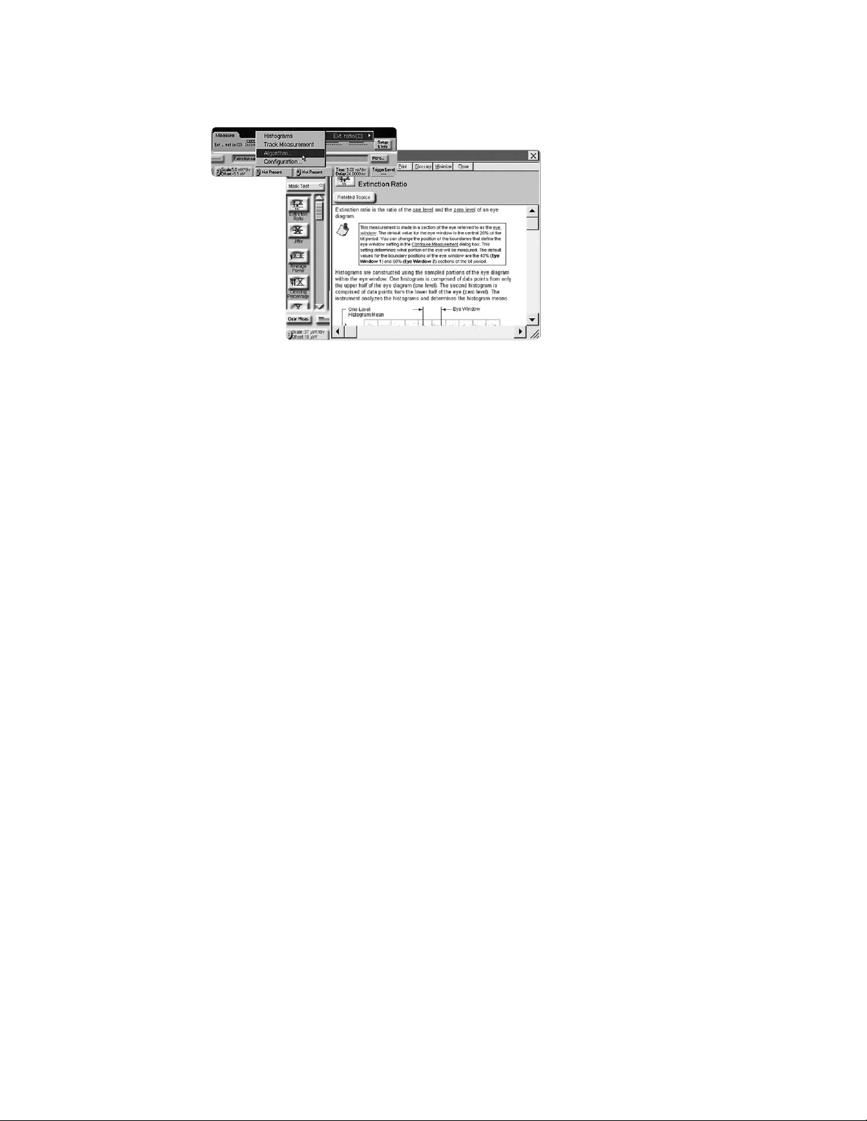
Built-in information system
The 86100C has a contextsensitive on-line manual
providing immediate answers
to your questions about using
the instrument. Links on the
measurement screen take you
directly to the information you
need including algorithms for
all of the measurements. The on-line
manual includes technical
specifications of the mainframe and
plug-in modules. It also provides
useful information such as the
mainframe serial number, module
serial numbers, firmware revision
and date, and hard disk free space.
There is no need for a large paper
manual consuming your shelf space.
File sharing and storage
Use the internal 40 GB hard drive to
store instrument setups, waveforms,
or screen images. A 64MB USB
memory stick is included with the
mainframe. Combined with the USB
port on the front panel this provides
for quick and easy file transfer.
Images can be stored in formats
easily imported into various
programs for documentation and
further analysis. LAN interface is
also available for network file
management and printing. An
external USB CD-RW drive is
included with the mainframe. This
enables easy installation of software
applications as well as storage of
large amounts of data.
Powerful display modes
Use gray scale and color graded trace
displays to gain insight into device
behavior. Waveform densities are
mapped to color or easy-to-interpret
gray shades. These are infinite
persistence modes where shading
differentiates the number of times
data in any individual screen pixel
has been acquired.
Internal triggering
through clock recovery
Typically an external timing
reference is used to synchronize the
oscilloscope to the test signal. In
cases where a trigger signal is not
available, clock recovery modules are
available to derive a timing reference
directly from the waveform to be
measured. The Agilent 8349XA series
of clock recovery modules are
available for electrical, multimode
optical, and single-mode optical
input signals. All 8349XA modules
have excellent jitter performance to
ensure accurate measurements. Each
clock recovery module is designed to
synchronize to a variety of common
transmission rates.
Clock recovery loop bandwidth
The Agilent clock recovery modules
have two loop bandwidth settings.
Loop bandwidth is very important
in determining the accuracy of your
waveform when measuring jitter, as
well as testing for compliance.
• Narrow loop bandwidth provides
a clean system clock for accurate
jitter measurements
• Wide loop bandwidth in some
applications is specified in the
standards for compliance testing.
It allows the recovered clock to
track the data and is useful for
extracting a signal that may have
propagated through a complex
network and have large amounts of
jitter. While this obviously negates
any ability to quantify the jitter, it
does allow other parameters of an
eye to be measured.
Note: When using recovered clocks
for triggering, the amount of jitter
observed will depend on the loop
bandwidth. As the loop bandwidth
increases, more jitter is “tracked
out” by the clock recovery resulting
in less observed jitter. This is
desired by many standards, but
it is important in a measurement
environment to understand the
effect that the clock recovery has on
the quantity of jitter being measured.

Waveform autoscaling
Autoscaling provides quick horizontal and vertical scaling
of both pulse and eye-diagram (RZ and NRZ) waveforms.
Time domain reflectometery/time domain
transmission (TDR/TDT)
High-speed design starts with the physical structure.
The transmission and reflection properties of electrical
channels and components must be characterized to
ensure sufficient signal integrity. Ref lections and signal
distortions must be kept at a minimum. Use TDR and
TDT to optimize microstrip lines, PC board traces, SMA
edge launchers and coaxial cables.
Calibration techniques, unique to the 86100C, provide
highest precision by removing cabling and fixturing
effects from the measurement results. Translation of
TDR data to complete single-ended, differential, and
mixed mode S-parameters are available through the
N1930A Physical Layer Test System software. Higher
two-event resolution and ultra high-speed impedance
measurements are facilitated through TDR pulse
enhancers from Picosecond Pulse Labs
1
.
Gated triggering
Trigger gating port allows easy external control of data
acquisition for circulating loop or burst-data
experiments. Use TTL-compatible signals to control
when the instrument does and does not acquire data.
Easier calibrations
Calibrating your instrument has been simplified by
placing all the performance level indicators and
calibration procedures in a single high-level location.
This provides greater confidence in the measurements
made and saves time in maintaining equipment.
Stimulus response testing
Using the Agilent N490XA Serial BERT
Error performance analysis represents an essential part
of digital transmission test. The Agilent 86100C and
N490XA Serial BERT have similar user interfaces and
together create a powerful test solution.
Transitioning from the Agilent 83480A and
86100A/B to the 86100C
While the 86100C has powerful new functionality that
its predecessors don’t have, it has been designed to
maintain compatibility with the Agilent 86100A, 86100B
and Agilent 83480A digital communications analyzers
and Agilent 54750A wide-bandwidth oscilloscope. All
modules used in the Agilent 86100A/B, 83480A and
54750A can also be used in the 86100C. The remote
programming command set for the 86100C has been
designed so that code written for the 86100A or 86100B
will work directly. Some code modifications are required
when transitioning from the 83480A and 54750A, but
the command set is designed to minimize the level of
effort required.
8
1
Picosecond Pulse Labs (www.picosecond.com)
 Loading...