


Errata
8590 E-series and L-series
User's Guide
08590-90301
July 1998
Title & Document Type:
Manual Part Number:
Revision Date:
HP References in this Manual
This manual may contain references to HP or Hewlett-Packard. Please note that HewlettPackard's former test and measurement, semiconductor products and chemical analysis
businesses are now part of Agilent Technologies. We have made no changes to this
manual copy. The HP XXXX referred to in this document is now the Agilent XXXX.
For example, model number HP8648A is now model number Agilent 8648A.
About this Manual
We’ve added this manual to the Agilent website in an effort to help you support your
product. This manual provides the best information we could find. It may be incomplete
or contain dated information, and the scan quality may not be idea l. If we find a better
copy in the future, we will add it to the Agilent website.
Support for Your Product
Agilent no longer sells or supports this product. You will find any other available
product information on the Agilent Test & Measurement website:
www.tm.agilent.com
Search for the model number of this product, and the resulting product page will guide
you to any available information. Our service centers may be able to perform calibration
if no repair parts are needed, but no other support from Agilent is available.

User’s
Guide
HP 8590 E-Series and
L-Series Spectrum Analyzers
HEWLETT
c?ii
HP Part No. 08590-90301 Supersedes: 08590-90234
Printed in USA July 1998
PACKARD

Notice.
The information contained in this document is subject to change without notice.
Hewlett-Packard makes no warranty of any kind with regard to this material, including
but not limited to, the implied warranties of merchantability and fitness for a particular
purpose. Hewlett-Packard shall not be liable for errors contained herein or for incidental or
consequential damages in connection with the furnishing, performance, or use of this material.
@Copyright 1994, 1995, 1998 Hewlett-Packard Company

Certification
Hewlett-Packard Company certifies that this product met its published specifications at the
time of shipment from the factory. Hewlett-Packard further certifies that its calibration
measurements are traceable to the United States National Institute of Standards and
Technology, to the extent allowed by the Institute’s calibration facility, and to the calibration
facilities of other International Standards Organization members.
Warranty
This Hewlett-Packard instrument product is warranted against defects in material and
workmanship for a period of one year from date of shipment. During the warranty period,
Hewlett-Packard Company will, at its option, either repair or replace products which prove to
be defective.
For warranty service or repair, this product must be returned to a service facility designated by
HP Buyer shall prepay shipping charges to HP and HP shall pay shipping charges to return the
product to Buyer. However, Buyer shall pay all shipping charges, duties, and taxes for products
returned to HP from another country.
HP warrants that its software and firmware designated by HP for use with an instrument will
execute its programming instructions when properly installed on that instrument. HP does not
warrant that the operation of the instrument, or software, or firmware will be uninterrupted or
error-free.
Limitation of Warranty
The foregoing warranty shall not apply to defects resulting from improper or inadequate
maintenance by Buyer, Buyer-supplied software or interfacing, unauthorized modification or
misuse, operation outside of the environmental specifications for the product, or improper
site preparation or maintenance.
NO OTHER WARRANTY IS EXPRESSED OR IMPLIED. HP SPECIFICALLY DISCLAIMS
THE IMPLIED WARRANTIES OF MERCHANTABILITY AND FITNESS FOR A PARTICULAR
PURPOSE.
Exclusive Remedies
THE REMEDIES PROVIDED HEREIN ARE BUYER’S SOLE AND EXCLUSIVE REMEDIES.
HP SHALL NOT BE LIABLE FOR ANY DIRECT, INDIRECT, SPECIAL, INCIDENTAL, OR
CONSEQUENTIAL DAMAGES, WHETHER BASED ON CONTRACT, TORT, OR ANY OTHER
LEGAL THEORY.
Assistance
Product maintenance agreements and other customer assistance agreements are available for
Hewlett-Rxkard products.
Fbr any assistance, contact your nearest
Hewlett-Rxckard
Sales and
Service Ojice.
. . .
III

Safety Symbols
The following safety symbols are used throughout this manual. Familiarize yourself with each
of the symbols and its meaning before operating this instrument.
Caution
Warning
-
!
A
C6
0
@
I
Caution denotes a hazard. It calls attention to a procedure that, if not
correctly performed or adhered to, would result in damage to or destruction
of the instrument. Do not proceed beyond a caution sign until the indicated
conditions are fully understood and met.
Warning denotes a hazard. It calls attention to a procedure which, if not
correctly performed or adhered to, could result in injury or loss of life.
Do not proceed beyond a warning note until the indicated conditions are
fully understood and met.
The instruction documentation symbol. The product is marked with this symbol
when it is necessary for the user to refer to the instructions in the documentation.
The CE mark is a registered trademark of the European Community.
(If accompanied by a year, it is when the design was proven.)
The CSA mark is a registered trademark of the Canadian Standards Association.
This symbol is used to mark the ON position of the power line switch.
w
I
0
n
P
ISM
This symbol indicates that the input power required is AC.
This symbol is used to mark the STANDBY position of the power line switch.
This symbol is used to mark the STANDBY/OFF position of the power line switch.
This symbol is used to mark the ON position of the power line switch.
This is a symbol of an Industrial Scientific and Medical Group 1 Class A product.
I-A

General Safety Considerations
Warning
Warning
Warning
Warning
Warning
This is a Safety Class I product (provided with a protective earthing
ground incorporated in the power cord). The mains plug shall only be
inserted in a socket outlet provided with a protective earth contact. Any
interruption of the protective conductor, inside or outside the instrument,
is likely to make the instrument dangerous. Intentional interruption is
prohibited.
No operator serviceable parts inside. Refer servicing to qualified
personnel. To prevent electrical shock, do not remove covers.
If this product is not used as specified, the protection provided by the
equipment could be impaired. This product must be used in a normal
condition (in which all means for protection are intact) only.
For continued protection against fire hazard, replace fuse only with same
type and ratings, (type
prohibited.
To prevent electrical shock, disconnect the BP 8590 Series equipment
from mains before cleaning. Use a dry cloth or one slightly dampened
with water to clean the external case parts. Do not attempt to clean
internally.
5A/250V).
The use of other fuses or materials is
Warning
Warning
Caution
Caution
There are many points inside the instrument which can, if contacted,
cause personal injury. Be extremely careful. Any adjustments or service
procedures that require operation of the instrument with the protective
covers removed should be performed only by trained service personnel.
This product conforms to Enclosure Protection Standard IP 2 0 according
to IEC-529, and protects against finger access to hazardous parts within
the enclosure.
This product presents a
when wet. This product conforms to Enclosure Protection Standard
IP 2 0 according to IEC-529, and therefore, it does not protect against the
admittance of water into the interior of the product.
Before switching on this instrument, make sure that the line voltage selector
switch is set to the voltage of the power supply and the correct fuse is
installed.
Always use the three-prong AC power cord supplied with this product. Failure
to ensure adequate earth grounding by not using this cord may cause product
damage.
signifiant
risk of electrical shock
if operated
V

Caution
VENTILATION REQUIREMENTS: When installing the product in a cabinet,
the convection into and out of the product must not be restricted. The ambient
temperature (outside the cabinet) must be less than the maximum operating
temperature of the product by 4°C for every 100 watts dissipated in the
cabinet. If the total power dissipated in the cabinet is greater then 800 watts,
then forced convection must be used.
Caution
This product is designed for use in Installation Catigory II and Pollution
Degree 2 per IEC-1010 and IEC-664 respectively.
Regulatory Information
Regulatory Information is in the Calibration Guide shipped with this product.
vi

HP 8590 Series Spectrum Analyzer Documentation Description
Manuals Shipped with Your Spectrum Analyzer
HP 8590 E-Series and L-Series Spectrum Analyzers User’s Guide
Describes how to prepare the analyzer for use.
Describes analyzer features.
Describes common applications.
Tells how to make measurements with your spectrum analyzer.
Includes error messages.
Calibration Guide
Provides analyzer specifications and characteristics.
Provides manual procedures to verify specifications.
Indicates the test equipment required for verification.
HP 8590 E-Series and L-Series Series Spectrum Analyzers Quick Reference Guide
Describes how to make a simple measurement with your spectrum analyzer.
Briefly describes the spectrum analyzer functions.
Lists all the programming commands.
Options
Option 910: Additional User’s Documentation
Provides an additional copy of the user’s guide, the calibration guide, and the quick
reference guide.
Option 915: Service Guide and Component-Level Information
Describes troubleshooting and repair of the spectrum analyzer.
Option 915 consists of two manuals:
HP 8590 E-Series and L-Series Spectrum Analyzers, and HP 8591 C Cable TV Analyzer;
Assembly-Level &pair Service
the analyzer.
HP 8590 E-Series and L-Series Spectrum Analyzers, and HP 8591C Cable TV Analyzer;
Component-Level &pair Service
of the analyzer.
Options 041 and 043: HP 8590 E-Series and L-Series Spectrum Analyzer and HP 8591C
Cable TV Analyzer Programmer 3 Guide
The HP 8590 E-Series and L-Series Spectrum Analyzer and HP 8591C Cable TV Analyzer
Programmer’s Guide describes analyzer operation via a remote controller (computer)
for Options 041 and 043. This manual is provided when ordering either Option 041 or
Option 043.
Ouide
describes adjustment and assembly level repair of
hide
provides information for component-level repair
How to Order Manuals
Each of the manuals listed above can be ordered individually. To order, contact your local
HP Sales and Service Office.
vii

Contents
1. Preparing For Use
What You’ll Find in This Chapter
Introducing the HP 8590 Series Spectrum Analyzers
Preparing Your Spectrum Analyzer for Use
Initial Inspection ...............................
Power Requirements
.............................
Setting the Line Voltage Selector Switch
Checking the Fuse
.............................
Power Cable ................................
Turning on the Analyzer for the First Time
Performing the Tracking-Generator Self-Calibration Routine
Performing the YTF Self-Calibration Routine
Electrostatic Discharge
............................
Reducing Damage Caused by ESD
2. Getting Started
What You’ll Learn in this Chapter
Getting Acquainted with the Analyzer
Front-Panel Features
Rear-Panel Features
............................
............................
Data Controls ...............................
HoldKey
................................
Knob ..................................
Number/Units Keypad ..........................
StepKeys
................................
Fine-Focus Control ............................
Screen Annotation ..............................
Menu and
Making a Measurement
Measurement Summary
Softkey
Overview
............................
...........................
Improving Accuracy with Self-Calibration Routines
Warm-Up Time
..............................
Performing the Tracking Generator Self-Calibration Routine (Option 010 or 011
only) .................................
Performing the YTF Self-Calibration Routine (HP
HP 85963 Only) ............................
When Is Self-Calibration Needed?
Memory Card Insertion and Battery Replacement
Changing the Memory Card Battery
Procedure to Change the Memory Card Battery
Analyzer Battery Information . . . . . . . . . . . . . . . . . . . . . . . .
.......................
.............
..................
...................
..................
.........
................
......................
.......................
....................
.........................
..............
8592L,
HP 85933, HP 85953, or
......................
...............
.....................
..............
l-l
l-l
1-2
l-3
1-4
1-4
1-5
1-6
l-8
1-9
l-10
l-11
1-12
2-l
2-l
2-l
2-5
2-8
2-8
2-8
2-8
2-9
2-9
2-10
2-12
2-13
2-15
2-16
2-16
2-17
2-18
2-18
2-19
2-20
2-21
2-22
Contents-l

3.
Making Basic Measurements
What You’ll Learn in This Chapter . . . . . . . . . . . . . . . . . . . . . .
Resolving Signals of Equal Amplitude Using the Resolution Bandwidth Function .
Resolving Small Signals Hidden by Large Signals Using the Resolution Bandwidth
Function . . . . . . . . . . . . . . . . . . . . . . . . . . . . . . . . .
Increasing the Frequency Readout Resolution Using the Marker Counter
Decreasing the Frequency Span Using the Marker Track Function
. . . . . . .
Peaking Signal Amplitude with Preselector Peak . . . . . . . . . . . . . . . .
Tracking Unstable Signals Using Marker Track and the Maximum Hold and
Minimum Hold Functions . . . . . . . . . . . . . . . . . . . . . . . . .
Comparing Signals Using Delta Markers . . . . . . . . . . . . . . . . . . . .
Measuring Low-Level Signals Using Attenuation, Video Bandwidth, and Video
Averaging . . . . . . . . . . . . . . . . . . . . . . . . . . . . . . . .
Identifying Distortion Products Using the RF Attenuator and Traces
. . . . .
Distortion from the Analyzer . . . . . . . . . . . . . . . . . . . . . . . .
Third-Order Intermodulation Distortion . . . . . . . . . . . . . . . . . . .
Using the Analyzer As a Receiver in Zero Frequency Span . . . . . . . . . . .
Measuring Signals Near Band Boundaries Using Harmonic Lock . . . . . . . . .
4. Making Measurements
What You’ll Learn in This Chapter
......................
Measuring Amplitude Modulation with the Fast Fourier Transform Function
Stimulus-Response Measurements
What Are Stimulus-Response Measurements?
Using a Spectrum Analyzer with a Tracking Generator
Stepping through the Measurement
Tracking Generator Unleveled Condition
Demodulating and Listening to an AM or FM Signal
Triggering on a Selected Line of a Video Picture Field
Making Reflection Calibration Measurements
Reflection Calibration
...........................
Measuring the Return Loss
.......................
................
............
.....................
..................
..............
.............
.................
.........................
Using the Gate Utility to Simplify Time-Gated Measurements (Option 105 only)
Using the Time-Gated Spectrum Analyzer Capability Without the Gate Utility . .
Introducing the Time-Gated Spectrum Analyzer Capability ..........
Using the Time-Gated Spectrum Analyzer Capability to View Pulsed RF ....
Example of a Time-Gated Pulsed RF Signal
.................
Setting the Gate Delay and Gate Length Properly, When NOT Using the Gate
Utility
.................................
Using the Self-Calibration Routines with Option 105 .............
Performing a Functional Check of Option 105
................
Using the One Button Measurements to Measure N dB Bandwidth, Percent
Amplitude Modulation, and Third Order Intercept
N dB Bandwidth Measurement
........................
Percent Amplitude Modulation Measurement
Third Order Intermodulation Measurement
(TOI)
.................
(TOI)
...........
................
Using the Power Measurement Functions to make Transmitter Measurements . .
Occupied Bandwidth and Transmitter Frequency Error ............
Adjacent Channel Power Ratio (ACP)
Channel Power Measurement
........................
....................
. . . .
...
3-l
3-2
3-4
3-6
3-7
3-8
3-9
3-12
3-15
_
3-20
3-20
3-22
3-24
3-26
4-l
4-2
4-7
4-7
4-8
4-8
4-12
4-13
4-15
4-17
4-17
4-18
.
4-19
4-22
4-22
4-24
4-26
4-33
4-35
4-36
4-39
4-39
4-40
4-41
4-43
4-43
4-45
4-48
Contents-2

5. Using Analyzer Features
What You’ll Learn in this Chapter
.......................
Use the Marker Table to List All the Active Markers
Use the Peak
Table
to List the Displayed Signals
Saving and Recalling Data from Analyzer Memory
ToSaveaState
To Recall a State
ToSaveaTrace
To Recall a Trace
..............................
..............................
..............................
.............................
To Save a Limit-Line Table or Amplitude Correction Factors
To Recall Limit-Line Tables or Amplitude Correction Factors
To Protect Data From Being Overwritten
..................
Saving and Recalling Data from the Memory Card
Preparing the Memory Card for Use
To Enter a Prefix
ToSaveaState
To Recall a State
ToSaveaTrace
To Recall a Trace
To Save a Display Image
To Recall a Display Image
To Save Limit-Line
To Recall Limit-Line
.............................
..............................
..............................
..............................
.............................
..........................
.........................
Tables
or Amplitude Correction Factors
Tables
or Amplitude Correction Factors
.....................
Saving and Recalling Programs with a Memory Card
To Save a Program
To Recall a Program
Using Limit-Line Functions
Procedure for Creating an Upper Limit Line
Limit-Line Functions
Editing, Creating, or Viewing a Limit-Line
Selecting the Type of Limit-Line Table
Selecting the Limit-Line
Selecting the Segment Number
.............................
............................
..........................
.................
............................
.................
..................
TPdble
Format
...................
......................
Selecting the Frequency or Time Coordinate
Selecting the Amplitude Coordinate
Selecting the Segment Type
Completing
‘Ihble
Entry and Activating Limit-Line Testing
.......................
Saving or Recalling Limit-Line Tables
....................
...................
Procedure for Creating an Upper and Lower Limit Line
Learn About the Analog+ Display Mode (Option 101 only)
Learn About the Windows Display
......................
Learn How to Enter Amplitude Correction Factors
Procedure for Creating Amplitude-Correction Factors
Amplitude-Correction Functions
......................
Editing or Viewing the Amplitude-Correction Tables
Selecting the Amplitude-Correction Point
Selecting the Frequency Coordinate
Selecting the Amplitude Coordinate
Completing
Table
Entry and Activating Amplitude Corrections
Saving or Recalling Amplitude Correction
External Keyboard
Using the External Keyboard
..............................
........................
External Keyboard Installation
....................
....................
......................
.................
lhbles
To Enter a Screen Title ..........................
To Enter Programming Commands
....................
..............
................
...............
.........
.........
...............
..........
.........
.............
................
.........
...........
...........
...............
............
............
.......
..............
5-l
5-2
5-4
5-6
5-6
5-6
5-7
5-7
5-8
5-8
5-8
5-10
5-11
5-12
5-12
5-13
5-13
5-13
5-14
5-14
5-15
5-15
5-16
5-16
5-16
5-18
5-18
5-22
5-22
5-22
5-23
5-23
5-25
5-25
5-26
5-28
5-28
5-29
5-32
5-33
5-35
5-36
5-38
5-38
5-38
5-39
5-39
5-39
5-39
5-40
5-42
5-42
5-42
5-43
Contents-3

To Enter a Prefix . . . . . . . . . . . . . . . . . . . . . . . . . . . .
6. Printing and Plotting
Printing or Plotting with HP-IB
........................
Printing Using an HP-IB Interface
Equipment
...............................
Interconnection and Printing Instructions
Plotting Using an HP-IB Interface
Equipment
...............................
Interconnection and Plotting Instructions
Printing or Plotting with RS-232
.......................
Printing Using an RS-232 Interface
Equipment
...............................
Interconnection and Printing Instructions
Plotting Using an RS-232 Interface
Equipment
...............................
Interconnection and Plotting Instructions
Printing after Plotting or Plotting after Printing
To print after plotting, press:
To plot after printing, press:
Printing With a Parallel Interface
Equipment
................................
.......................
.......................
.......................
Interconnection and Printing Instructions
Plotting to an HP LaserJet Printer
Equipment
................................
Interconnection and Plotting Instructions
......................
..................
......................
..................
.....................
..................
.....................
..................
...............
..................
......................
..................
5-43
6-1
6-4
6-4
6-4
6-7
6-7
6-7
6-10
6-10
6-10
6-10
6-14
6-14
6-14
6-17
6-17
6-17
6-18
6-18
6-18
6-21
6-21
6-21
7. Key Descriptions
Service Functions
Service Calibration Functions
Service Diagnostic Functions
Analyzer Functions
..............................
........................
........................
.............................
8. Key Menus
9.
If You Have A Problem
What You’ll Find in This Chapter ......
Before You Call Hewlett-Packard ......
Check the Basics
.............
Read the Warranty ............
Service Options
.............
How to Call Hewlett-Packard .......
How to Return Your Analyzer for Service . .
Service lag
...............
Original Packaging ............
Other Packaging
Error Messages
.............
..............
................
................
................
................
................
................
................
................
................
................
................
7-2
7-2
7-2
7-4
9-1
9-2
9-2
9-4
9-4
9-4
9-6
9-6
9-6
9-6
9-7
Contents-4

10.
Measurement Personalities, Options, and Accessories
What You’ll Find In This Chapter
Measurement Personalities
..........................
Broadcast Measurements Personality
CATV Measurements Personality
CATV System Monitor Personality
.......................
....................
......................
......................
Cable TV Measurements and System Monitor Personality
CDMA Measurements Personality
CT2-CA1
Measurements Personality
DECT Measurements Personality
Digital Radio Measurements Personality
EM1 Diagnostics Measurements Personality
GSMSOO
and DCS1800 Transmitter Measurements Personalities
Link Measurement Personality
NADC-TDMA Measurements Personality
Noise Figure Measurements Personality
PDC Measurements Personality
PHS Measurements Personality
Scalar Measurements Personality
Options
75Q
...................................
Input Impedance (Option 001)
Memory Card Reader (Option 003)
Precision Frequency Reference (Option 004)
......................
.....................
......................
...................
.................
.......................
...................
...................
.......................
.......................
......................
.....................
.....................
.................
LO and Sweep+Tune Outputs on Rear Panel (Option 009)
Tracking Generator (Option 010 and Option 011)
Protective
‘Ian
Operating/Carrying Case with Shoulder Strap (Option 015)
Protective Yellow Operating/Carrying Case with Shoulder Strap (Option 016)
HP-IB and Parallel Interface (Option 041)
RS-232 and Parallel Interface (Option 043)
Frequency Extension to 26.5
Frequency Extension to 26.5
GHz
with APC-3.5 Connector (Option 026)
GHz
with N-Type Connector (Option 027)
Front Panel Protective Cover (Option 040)
..................
..................
..................
Protective Soft Carrying Case/Back Pack (Option 042)
Improved Amplitude Accuracy for NADC bands (Option 050)
Improved Amplitude Accuracy for PDC bands (Option 051)
Improved Amplitude Accuracy for PHS (Option 052)
Improved Amplitude Accuracy for CDMA (Option 053)
Fast Time Domain Sweeps (Option 101)
...................
AM/FM Demodulator with Speaker and TV Sync Trigger Circuitry (Option 102)
Quasi-Peak Detector and AM/FM Demodulator With Speaker (Option 103)
Time-Gated Spectrum Analysis (Option 105)
CT2 Demodulator (Option 110)
.......................
.................
Group Delay and Amplitude Flatness (Option 111)
DECT Demodulator (Option 112)
Noise Figure (Option 119)
.........................
Narrow Resolution Bandwidths (Option 130)
......................
.................
Narrow Resolution Bandwidths and Precision Frequency Reference (Option 140)
DSP, Fast ADC and Digital Demodulator (Option 151)
PDUPHSNADCKDMA
GSM/DCS1800
Firmware for Option 151 (Option 163)
TV Picture Display (Option 180)
Firmware for Option 151 (Option 160)
......................
TV Sync Trigger Capability/Fast Time-Domain Sweeps and AM/FM Demodulator
(Option 301)
500 to
75fl
Matching Pad (Option 711)
Reduced Frequency Accuracy (Option 713)
..............................
....................
.................
...........
........
..........
...............
...
....
....
............
.........
..........
.............
............
...
..............
.............
........
.............
.
10-l
10-2
10-2
10-2
10-2
10-2
10-2
10-3
10-3
10-3
10-3
10-3
10-4
10-4
10-4
10-4
10-4
10-4
IO-5
10-5
10-5
10-5
10-5
10-6
10-6
10-6
10-6
10-7
10-7
10-7
10-7
10-7
10-8
10-8
10-8
10-8
10-8
10-9
10-9
10-9
1 o-9
10-9
10-10
10-10
10-10
10-10
10-10
10-11
10-l 1
10-11
10-12
10-12
10-12
Contents-5
Rack Mount Kit Without Handles (Option 908)
Rack Mount Kit With Handles (Option 909)
IJser’s Guide and Calibration Guide (Option 910)
................
.................
...............
Service Documentation (Option 915)
BenchLink
Accessories
RF and Transient Limiters
5OB
Transmission/Reflection Test Set
Scalar
5OQ2/75fl
750 Matching Transformer
RF Bridges
AC Power Source
ACProbe
Broadband Preamplifiers and Power Amplifiers
Burst Carrier Trigger
Close Field Probes
External Keyboard
HP-IB Cable
Memory Cards
Parallel Interface Cable
PC Interface and Report Generator software
Spectrum Analyzer (Option
‘B70) 1 1 1 1 : 1 : : 1 : : : : : : 1 1
.................................
.........................
....................
5OQ
Transmission/Reflection Test Set
Minimum Loss Pad
.........................
.................
.........................
................................
.............................
.................................
...............
............................
.............................
.............................
................................
...............................
..........................
................
Plotter ..................................
Printer
Rack Slide Kit
RS-232 Cable
Transit Case
..................................
...............................
...............................
................................
IO-12
10-12
10-12
10-12
10-12
10-13
10-13
10-13
10-13
10-13
10-13
10-13
10-14
10-14
10-14
10-14
10-15
10-15
10-15
10-15
10-15
lo-16
lo-16
lo-16
lo-16
lo-16
lo-16
A. SRQ
Service Requests
Status Byte Definition
Service Request Activating Commands
Glossary
Index
...............................
...........................
...................
A-l
A-l
A-2
Contents-6

Figures
l-l. HP 8590 Series Spectrum Analyzer
1-2. Setting the Line Voltage Selector Switch
l-3. Checking the Line Fuse
l-4. Reference Connector
1-5. Example of a Static-Safe Work Station
2-l. Front-Panel Feature Overview
2-2. Rear-Panel Feature Overview
2-3. Adjusting the Fine Focus
2-4. Screen Annotation
2-5. Relationship between Frequency and Amplitude
2-6. Reading the Amplitude and Frequency
2-7. Inserting the Memory Card
2-8. Memory Card Battery Date Code Location
2-9. Memory Card Battery Replacement
2-10. Rear-Panel Battery Information Label
3-l. Set-Up for Obtaining Two Signals
3-2. Resolving Signals of Equal Amplitude
3-3. Resolution Bandwidth Requirements for Resolving Small Signals
3-4. Signal Resolution with a 10 kHz Resolution Bandwidth
3-5. Signal Resolution with a 30 kHz Resolution Bandwidth
3-6. IJsing the Marker Counter
3-7. After Zooming In on the Signal
3-8. Peaking Signal Amplitude Using Preselector Peak
3-9. Using Marker Tracking to Track an Unstable Signal
3-10. Viewing an Unstable Signal Using Max Hold A
3-l 1. Viewing an Unstable Signal With Max Hold, Clear Write, and Min Hold
3-12. Placing a Marker on the CAL OUT Signal
3-13. Using the Marker Delta Function
3-14. Using the Marker to Peak/Peak Function
3-15. Frequency and Amplitude Difference between Signals
3-16. Low-Level Signal
3-17. Using 0 dB Attenuation
3-18. Decreasing Resolution Bandwidth
3-
19. Decreasing Video Bandwidth
3-20. Using the Video Averaging Function
3-2 1. Harmonic Distortion
3-22. RF Attenuation of 10
3-23. No Harmonic Distortion
3-24. Third-Order Intermodulation Equipment Setup
3-25. Measuring the Distortion Product
3-26. Viewing an AM Signal
3-27. Measuring Modulation in Zero Span
3-28. Using Harmonic Lock
3-29. Harmonic Locking Off
4-l. FFT Annotation
4-2. Percent Amplitude Modulation Measurement
.............................
.............................
..............................
..........................
............................
........................
..........................
.........................
.........................
..........................
........................
............................
..........................
dB
..........................
...........................
...........................
...........................
.....................
...................
...................
.......................
...............
...................
..................
.....................
....................
......................
....................
.......
............
............
.......................
..............
.............
................
..................
......................
..................
............
......................
....................
...............
......................
.....................
................
....
l-l
1-4
1-5
1-8
l-11
2-2
2-5
2-9
2-10
2-14
2-15
2-19
2-20
2-21
2-22
3-2
3-3
3-4
3-5
3-5
3-6
3-7
3-8
3-10
3-11
3-11
3-12
3-13
3-13
3-14
3-15
3-16
3-16
3-17
3-19
3-20
3-21
3-21
3-22
3-23
3-25
3-25
3-27
3-27
4-2
4-5
Contents-7

4-3. Block Diagram of a Spectrum Analyzer/Tracking-Generator Measurement System
4-4. Transmission Measurement Test Setup
4-5. Tracking-Generator Output Power Activated
4-6. Spectrum Analyzer Settings According to the Measurement Requirement
4-7. Decrease the Resolution Bandwidth to Improve Sensitivity
4-8. Manual Tracking Adjustment Compensates for Tracking Error
4-9. Normalized Trace
.............................
4-10. Measure the Rejection Range with Delta Markers
4-l 1. Demodulation of an FM Signal
.......................
4-12. Continuous Demodulation of an FM Signal
4-13. Triggering on an Odd Field of a Video Format
4-14. Triggering on an Even Field of a Video Format
4-15. Reflection Measurement Short Calibration Test Setup
4-16. Measuring the Return Loss of the Filter
4-
17. Time-Gate Utility Display
..........................
4-18. Viewing Time-Sharing of a Frequency with an Oscilloscope
4-19. Viewing Time-Sharing of a Frequency with a Spectrum Analyzer
4-20. Pulse Repetition Interval and Pulse Width (with Two Signals Present)
4-21. Test Setup for Option 105
.........................
4-22. Setting the Center Frequency, Span, and Reference Level
4-23. Setting the Sweep Time
..........................
4-24. Setting the Gate Delay and Gate Length Using an Oscilloscope
4-25. Using Time-Gating to View Signal 1
4-26. Placing the Gate Output During the Second Signal
4-27. Viewing Both Signals with Time-Gating
4-28. Gate Not Occurring During the Pulse
4-29. Gate is Occurring at the Beginning of the Pulse
4-30. Self-Calibration Data Results
........................
4-31. Rear Panel Connections for Option 105
4-32. Gate On
4-33. Using the Level Gate Control
4-34. N dB Bandwidth Measurement
..................................
........................
.......................
4-35. Percent Amplitude Modulation Measurement
4-36. Third-Order Intermodulation Measurement
4-37. Occupied Bandwidth
4-38. Adjacent Channel Power
............................
..........................
4-39. Adjacent Channel Power Extended
4-40. Adjacent Channel Power Graph
4-41. Channel Power
4-42. Channel Power Graph
5-1. Marker
5-2. Peak
‘Ihble
‘Ihble
Display
..............................
...........................
Display
............................
.............................
5-3. Inserting the Memory Card
5-4. Typical Limit-Line Display
.......................
.........................
.........................
5-5. The Completed Limit-Line Table
5-6. Limit-Line Segments
5-7. Segment Types
............................
..............................
5-8. Upper and Lower Limit-Line Testing
5-9. Analog+ Display Mode
5-10. Windows Display Mode
5-
11. Amplitude-Correction Display
5-
12. Completed Amplitude-Correction
5-13. Amplitude-Correction Points
6-1. Three Printouts Per Page
6-2. Plots Per Page
...............................
...........................
...........................
.......................
........................
..........................
....................
.................
...
..........
........
..............
..................
................
...............
.............
...................
..........
.......
.....
..........
........
.....................
..............
...................
....................
...............
...................
................
.................
.....................
......................
....................
Iable
...................
4-7
4-8
4-9
4-9
4-10
4-10
4-11
4-12
4-13
4-14
4-15
4-16
4-17
4-18
4-19
4-23
4-24
4-25
4-27
4-28
4-28
4-29
4-30
4-31
4-32
4-33
4-33
4-36
4-36
4-37
4-38
4-39
4-40
4-42
4-44
4-46
4-46
4-47
4-48
4-49
5-2
5-4
5-11
5-19
5-21
5-24
5-27
5-30
5-32
5-33
5-35
5-37
5-38
6-2
6-3
Contents-8

6-3.
ThinkJet
Printer Switch Settings
6-4. HP-IB to Centronics Converter Setup
6-5. Printer Configuration Menu Map
6-6. HP 7475A Plotter Switch Settings
6-7. Plot Configure Menu
............................
6-8. 9600 Baud Settings for Serial Printers
6-9. Printer Configure Menu
6-10. Connecting the HP
6-l 1. Baud Rate Menu Map
6-12. Plot Configure Menu
7550A/B
..........................
Plotter
...........................
............................
6-13. Parallel Printer Switch Settings
6-14. Printer Configuration Menu Map
6-15. Plot Configure Menu
............................
7-l. Memory Card Catalog Information
7-2. Analyzer Memory Catalog Information
7-3. CATALOG ON EVENT Display
......................
....................
......................
......................
....................
.....................
.......................
......................
.....................
...................
.......................
7-4. Connecting a Printer to the Spectrum Analyzer
...............
6-4
6-5
6-5
6-7
6-8
6-11
6-12
6-15
6-15
6-16
6-18
6-19
6-22
7-17
7-18
7-20
7-29
Contents-9

lhbles
l-l. Accessories Supplied with the Spectrum Analyzer
1-2. Power Requirements
l-3. AC Power Cables Available
1-4. Static-Safe Accessories
2-l. RF Output Frequency Range
2-2. Screen Annotation
2-3. Screen Annotation for Trace, Trigger, and Sweep Modes
4-1. Determining Spectrum Analyzer Settings for Viewing a Pulsed RF Signal
4-2. Pulse Generator Test Setup Settings
4-3. Signal Generator Test Setup Settings
4-4. Gate Delay, Resolution Bandwidth, Gate Length, and Video Bandwidth Settings
4-5. Sweep Time Settings
5-1. Summary of Save and Recall Operations, Analyzer Memory ..........
5-2. Comparison of Analyzer Memory and Memory Card Operations
5-3. Save and Recall Functions Using Memory Card
5-8. External Keyboard Functions
7-1. Commands Not Available with Analog+ Operation ..............
7-2. Center Frequency and Span Settings for Harmonic Bands
7-3. Memory Card Catalog Information
7-4. Analyzer Memory Catalog Information *
7-5. CATALOG ON EVENT Display Description ..................
7-6. Default Configuration Values
7-7. Compatibility of FFT With Other Functions .................
7-8. Commands Altered/Not Available within the Gate Utility
7-9. Functions Which Exit The Windows Display Format
7-10. Model Specific Preset Conditions
7-
11. Common Preset Conditions
7-12. Preset Spectrum Conditions for All Models
7-13. HP 85933, HP
9-1. Hewlett-Packard Sales and Service Offices ..................
A-l. Status Byte Definition
............................
.........................
...........................
........................
.............................
.....................
....................
............................
........................
.....................
...................
........................
......................
.........................
8594E,
HP 85953, and HP 8596E : : : : : : : : : : : : : :
...........................
..............
...........
...
........
...............
..........
...........
.............
1-3
1-4
1-7
1-12
2-4
2-11
2-12
4-26
4-27
4-28
4-34
4-35
5-9
5-10
5-17
5-40
7-9
7-12
7-17
7-19
7-20
7-32
7-43
7-47
7-61
7-66
7-67
7-68
7-71
:
9-5
A-2
Contents-l 0

Preparing For Use
What You’ll Find in This Chapter
This chapter describes the process of getting the spectrum analyzer ready to use when you
have just received it. See “Preparing Your Spectrum Analyzer For Use” for the process steps.
The process includes initial inspection, setting up the unit for the selected ac power source,
and performing automatic self-calibration routines. Information about static-safe handling
procedures is also included in this chapter.
Introducing the HP 8590 Series Spectrum Analyzers
1
Figure l-l. HP 8590 Series Spectrum Analyzer
The HP 8590 Series spectrum analyzers are small, lightweight test instruments that cover the
RF and microwave frequency ranges:
HP
HP
HP
HP
HP
HP
HP
HP
859OL,
85913,
8592L,
85933,
85943,
8594L,
85953,
85963,
9
kHz to 1.8
9
kHz to 1.8
9
kHz
to 22
9
kHz
to 22
9
kHz to 2.9
9
kHz
to 2.9
9
kHz to 6.5
9
kHz
to 12.8
GHz
GHz
GHz
GHz
GHz
GHz
GHz
GHz
Preparing For Use
l-1

Preparing Your Spectrum Analyzer for Use
Detailed information for all of the steps in this process is included in this chapter.
1. Unpack the spectrum analyzer and inspect it.
2. Verify that all of the accessories and documentation has been shipped.
3. Check that the line voltage selector is set to the proper voltage.
4. Check that the correct fuse is in place.
Warning
Caution
5. Connect the power cable to the spectrum analyzer and turn it on.
Warning
6. Execute the self-calibration routines.
Failure to ground the spectrum analyzer properly can result in personal
injury. Use an ac power outlet that has a protective earth contact.
NOT defeat the earth grounding protection by using an extension cable,
power cable, or autotransformer without a protective ground conductor.
Do
not connect ac power until you have verified that the line voltage is correct,
the proper fuse is installed, and the line voltage selector switch is properly
positioned, as described in the following paragraphs. Damage to the equipment
could result.
Install the product so that the detachable power cord is readily
identifiable and easily reached by the operator. The detachable power
cord is the product disconnecting devise. It disconnects the mains
circuits from the mains supply before other parts of the product. The
front panel switch is only a standby switch and is not a LINE switch.
Alternatively, an externally installed switch or circuit breaker (which is
readily identifiable and is easily reached by the operator) may be used as a
disconnecting device.
DO
1-2 Preparing For Use

Initial Inspection
Inspect the shipping container for damage. If the shipping container or cushioning material is
damaged, keep it until you have verified that the contents are complete and you have tested
the spectrum analyzer mechanically and electrically.
Table l-l contains the accessories shipped with the spectrum analyzer. If the contents are
incomplete or if the spectrum analyzer does not pass the verification tests in the calibration
guide, notify the nearest Hewlett-Packard office. If the shipping container is damaged or the
cushioning material shows signs of stress, also notify the carrier. Keep the shipping materials
for the carrier’s inspection. The HP office will arrange for repair or replacement without
waiting for a claim settlement.
If the shipping materials are in good condition, retain them for possible future use. You may
wish to ship the spectrum analyzer to another location or to return it to Hewlett-Packard for
service. See “How to Return Your Analyzer for Service,”
about shipping materials.
in Chapter 9 for more information
Note
32-kilobyte Memory Card
Memory Card Holder
Adapter, Type N (m) to BNC (f)
Two Adapters, BNC (m) to BNC (f)
Adapter, BNC (m) to SMA (f)
Connector, APC-3.5 mm (f) to (f)
Reference Connector
Zable, 5OQ,
Zable,
Zable,
Zable,
‘ower
BNC
SMA (m) to type N (m)
750, BNC
SMA (m) to SMA (m)
cable
If cleaning is necessary, use a damp cloth only.
lhble
l-l. Accessories Supplied with the Spectrum Analyzer
Description
HP Part Number
0950-1964
9222-1545
1250-0780
1250-0076
HP 1250-1700
HP
5061-5311
1250-1499
8120-2682
8120-5148
5062-6452
08592-60061
See Table 1-3
Comments
Shipped with analyzer. HP
and HP 8594L must include Option 003.
Shipped with analyzer. HP
and HP8594L must include Option 003.
Not shipped with Option 001. Two adapters
are shipped with Option 010.
Shipped with Option 105 only. The adapters
can be used to connect cables to the
rear-panel connectors.
Shipped with Option 026 only.
Shipped with Option 026 only.
Shipped connected between the 10 MHz REF
OUT and the EXT REF IN on the rear panel of
the analyzer. Not shipped with HP 8590L
option 713.
Not shipped with Options 001, 011, or 026.
Shipped with HP
HP
85963.
Shipped with Options 001 or 011 only.
Shipped with Option 026 only.
Shipped with analyzer.
8592L,
Not shipped with Option 026.
859OL,
HP
8592L,
859OL,
HP
8592L,
HP 85933, and
Preparing For Use 1-3

Power Requirements
The spectrum analyzer is a portable instrument and requires no physical installation other than
connection to a power source.
Warning
Caution
Failure to ground the spectrum analyzer properly can result in personal
injury. Use an ac power outlet that has a protective earth contact. DO
NOTdefeat
power cable, or autotransformer without a protective ground conductor.
Do not connect ac power until you have verified that the line voltage is correct,
the proper fuse is installed, and the line voltage selector switch is properly
positioned, as described in the following paragraphs. Damage to the equipment
could result.
the earth grounding protection by using an extension cable,
‘Ihble
1-2. Power Requirements
Setting the Line Voltage Selector Switch
Caution
Before connecting the spectrum analyzer to the power source, you must set the
rear-panel voltage selector switch correctly to adapt the spectrum analyzer
to the power source. An improper selector switch setting can damage the
spectrum analyzer when it is turned on.
Set the instrument’s rear-panel voltage selector switch to the line voltage range
(115 V or 230 V) corresponding to the available ac voltage. See Figure l-2. Insert a small
screwdriver or similar tool in the slot and slide the switch so that the proper voltage label is
visible.
,,*-\, ‘I/ “\
Figure l-2. Setting the Line Voltage Selector Switch
1-4 Preparing For Use

Checking the Fuse
The recommended fuse is size 5 by 20 mm, rated
used with input line voltages of 115 V or 230 V. Its HP part number is 2110-0709.
With an input line voltage of 115 V an alternate fuse can be used. In areas where the
recommended fuse is not available, a size 5 by 20 mm, rated fast blow, 5 A, 125 V (ULXSA
approved) fuse may be substituted. Its HP part number is 2110-0756.
The line fuse is housed in a small container beside the rear-panel power connector. See
Figure l-3. The container provides space for storing a spare fuse, as shown in the figure.
To check the fuse, insert the tip of a screwdriver in the slot at the middle of the container and
pry gently to extend the container.
Warning
Note
The fuse closest to the spectrum analyzer is the fuse in use. If the fuse is defective or missing,
install a new fuse in the proper position and reinsert the fuse container.
For continued protection against fire hazard replace line fuse only with
same type and rating
prohibited.
The fuse container is attached to the line module; it cannot be removed.
(5A/250V).
F5A,
250 V (IEC approved). This fuse may be
The use of other fuses or material is
Figure l-3. Checking the Line Fuse
Preparing For Use
l-5

Power Cable
The spectrum analyzer is equipped with a three-wire power cable, in accordance with
international safety standards. When connected to an appropriate power line outlet, this cable
grounds the instrument cabinet.
Warning
Various power cables are available to connect the spectrum analyzer to the types of ac power
outlets unique to specific geographic areas. The cable appropriate for the area to which the
spectrum analyzer is originally shipped is included with the unit. You can order additional ac
power cables for use in different areas.
the plug configurations, and identifies the geographic area in which each cable is appropriate.
Failure to ground the spectrum analyzer properly can result in personal
injury. Before turning on the spectrum analyzer, you must connect its
protective earth terminals to the protective conductor of the main power
cable. Insert the main power cable plug only into a socket outlet that has
a protective earth contact. DO NOT defeat the earth-grounding protection
by using an extension cable, power cable, or autotransformer without a
protective ground conductor.
If you are using an autotransformer, make sure its common terminal is
connected to the protective earth contact of the power source outlet
socket.
Table
l-3 lists the available ac power cables, illustrates
1-6 Preparing For Use

lhble
1-3. AC Power Cables Available
PLUG TYPE * *
25O’J
E
0 0
N
L
A
125V
25O’d
,A---,
i :
CABLE
HP PART
rIIJMl3ER
8120~1363
8 120-0696
8120~1683
E120-1692
8 120-
1348
8120-1538
8120-1378
8 120-4753 Straight
8120-1521
8120-4754
8120-5182
8120-5181
DESCRIPTI’JN
Strnight
9om
Strn,ght*
9o”
Stratght
9o”
Straight*
9o”
Straight*
go0
9oa
stro1gt,t*
30*
PLUG
BS1363A
NZSSlSB/ASCl
*
CEE7-II
NEMA5S15P
NEMA5-
NEMA5S15P
CABLE
L E rl G T H
:M ~INCHEC,)
229 (90)
229
(90)
201
12
1
1
:P
~
(79)
221
(87)
201 (79)
201
(79j
203
(80)
203 (80)
203
(80)
230 (90)
203
(80)
230
(9Oj
200
(78)
200
(78)
CABLE
COLOR
Mint Gray
Mint Gray
Grily
Gray
I
i4lnt
Gray
Mint Gray
Blnck
Block
Jade
Gray
Jade Gray
Jade Gray
Jade Gray
Jade
Grny
.Jade Gray
FOR
I II
COUI‘JTR i
c
;reot Brltuin.
/
:yprus,
<
;ingnpore,
Zimbabwe
Argen
t i
Auitrulla,
New
Zen I
Mainland
E
:ast and \Nest
E
.urope,
A
fricon Replubl ic
InI
L
F
‘epubl IC
unpnlnrized
(
r
nnny not 19ns)
In,
i
C
:anocla,
apon (100 $4
_J
;
‘00
;olombia.
(
F
‘hl
‘
<audio Arobin,
1
-0iwan
Israel
Centrnl
ted Arab
ted
V), eraz I,
I I
spines,
IJSE
I‘Nigerin.
~10,
anJ,
China
States
0,~
Mexlcr
I”
.\f\ ‘”
(:
ii Pnrt
HP Port
ii #
E = Earth
number for
rlurnber
for
Lr~und:
industry
pluq IS
complrie
L = Line, N =
cable, including
Identifier
r>leutraI
for plug
pll~g
-
Number shown for
orlly
cable I:;
Preparing For Use
l-7
Turning on the Analyzer for the First Time
When you turn the spectrum analyzer on for the first time, you should perform frequency and
amplitude self-calibration routines to generate correction factors and indicate that the unit is
functioning correctly. The spectrum analyzer should be allowed to warm-up for 30 minutes
before performing the self-calibration routines. See “When Is Self-Calibration Needed?”
in Chapter 2 for helpful guidelines on how often the self-calibration routines should be
performed.
Perform the following steps:
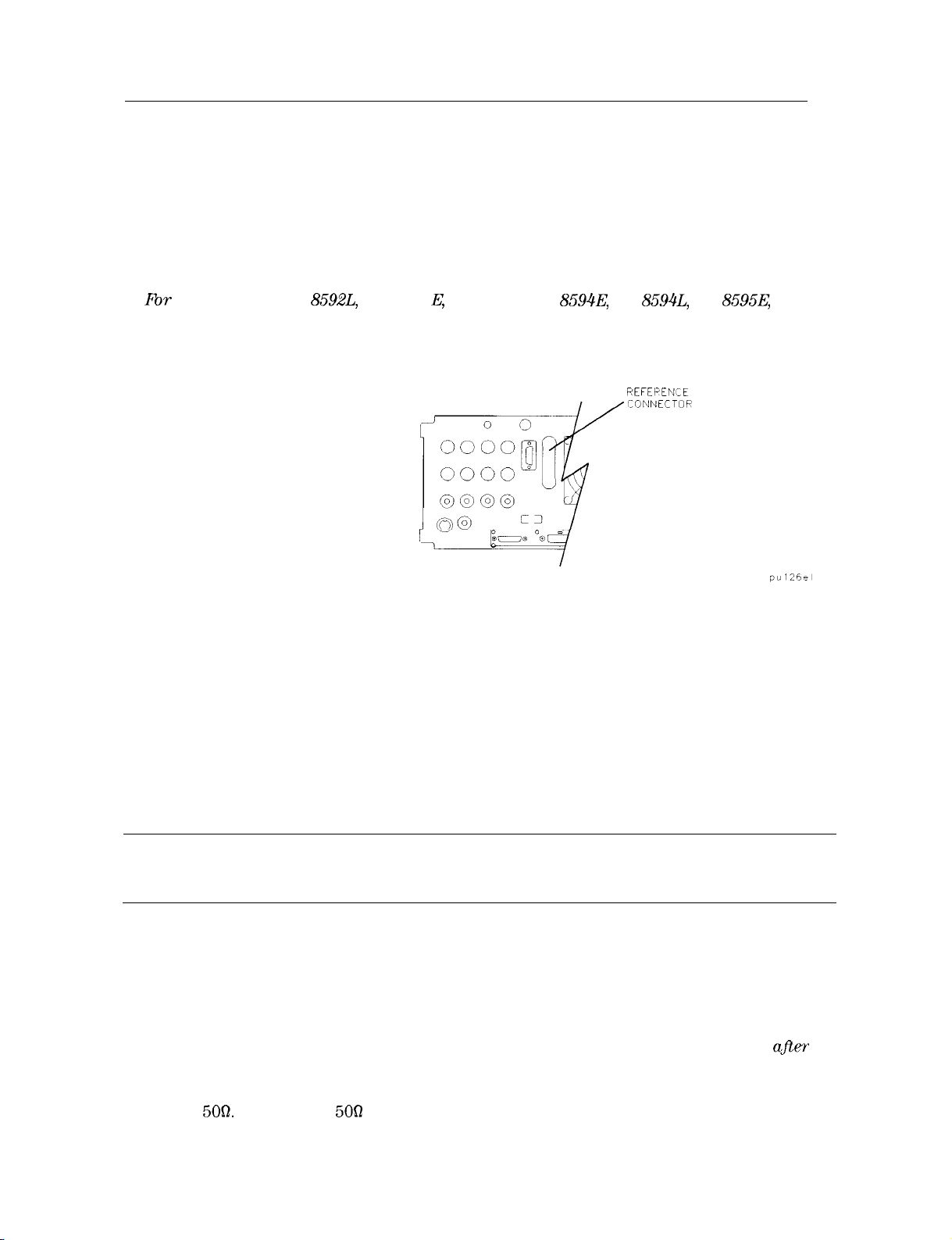
1. Fbr an HP 85901, HP
HP 85963 ensure the reference connector is connected between the 10 MHz OUTPUT and
EXT REF IN rear-panel connectors. See Figure l-4.
If you wish to use an external 10 MHz source as the reference frequency, disconnect the
reference connector from the rear-panel and connect an external reference source to the
EXT REF IN connector on the rear panel.
2. Plug the power cord into the spectrum analyzer.
3.
Press (LINE).
8592L,
HP 8591 E, HP 85933, HP
Figure 1-4. Reference Connector
8594E,
HP
REFEPENCE
8594L,
HP
8595E,
or
After a few seconds, the screen displays the firmware revision date in the YYMMDD format.
For example, 930522 indicates May 22, 1993. This is a change from previous revisions where
any firmware date used the DDMMYY format prior to 930506.
Note
If your spectrum analyzer is equipped with Option 021 (HP-IB interface), the appropriate
interface address (HP-IB ADRS : XX) also appears on the screen.
If your spectrum analyzer is equipped with Option 023 (RS-232 interface), the baud rate
(RS232 : XXXX) is displayed.
4. To meet spectrum analyzer specifications, allow a 30 minute warm-up before attempting to
make any calibrated measurements. Be sure to calibrate the spectrum analyzer only afler
the spectrum analyzer has met the operating temperature conditions.
5. Connect the type N (m) to BNC (f) connector (shipped with the spectrum analyzer) to the
INPUT
front-panel CAL OUT and the INPUT 500 connector. If the spectrum analyzer has Option
1-8 Preparing For Use
Record the firmware date and keep it for reference. If you should ever need to
call Hewlett-Packard for service or with any questions regarding your spectrum
analyzer, it will be helpful to have the firmware date readily available.
5OQ.
Connect the 500 coaxial cable (also shipped with the instrument) between the
001
(7562
input), use the 750 calibration cable shipped with the analyzer. Use only 750
connectors to avoid damage to the RF input connector.
Note
6. Perform the frequency and amplitude self-calibration routine by pressing (CAL) and
CAL FREQ & AMPTD . During the frequency routine, CAL: SWEEP, CAL: FREQ, and CAL: SPAN
are displayed as the sequence progresses. For an Option 102, CAL: FM GAIN + OFFSET is also
displayed.
During the amplitude routine, CAL; AMPTD, CAL: 3 dB BW, CAL:
displayed as the sequence progresses. CAL: DONE appears when the routine is completed.
Any failures or discrepancies produce a message on the screen; see Chapter 9.
7. When the frequency and amplitude self-calibration routines have been completed
successfully, store the correction factors by pressing CAL STORE.
The self-calibration routines calibrate the spectrum analyzer by generating correction factors.
The
softkey
memory that is saved when the spectrum analyzer is turned
automatically apply these factors in future measurements. If CAL STORE is not pressed, the
correction factors remain in effect until the spectrum analyzer is turned off.
Option 105 only: Remove all connections to the GATE TRIGGER INPUT
rear-panel connector before performing the self-calibration routines.
ATTEN,
CAL STORE stores the correction factors in the area of spectrum analyzer
off;
the spectrum analyzer will
and CAL:
LOGAMP
are
Performing the Tracking-Generator Self-Calibration Routine
For spectrum analyzers with Option 010 or 011, the tracking-generator self-calibration routine
should be performed prior to using the tracking generator.
Note
1. To calibrate the tracking generator, connect the tracking generator output (RF OUT
the spectrum analyzer INPUT 500 connector, using an appropriate cable and BNC-to-Type
N adapters. If the spectrum analyzer has Option 001 (750 input), use the
cable shipped with the analyzer. Use only
connector.
Note
2. Press the following spectrum analyzer keys:
CAL TRK GEN . TG SIGNAL NOT FOUND will be displayed if the tracking generator output is
not connected to the spectrum analyzer input.
3. To save this data in the area of spectrum analyzer memory that is saved when the spectrum
analyzer is turned off, press CAL STORE .
Since the tracking generator calibration routine depends on the accuracy of
the absolute amplitude level of the spectrum analyzer, the spectrum analyzer
amplitude calibration should be done prior to using CAL TRK GEM .
5OR)
to
75Q
calibration
75fl
connectors to avoid damage to the RF input
A low-loss cable should be used for accurate calibration. Use the
shipped with the spectrum analyzer. If the analyzer has Option 001 (75n input),
use the
75R
cable shipped with the spectrum analyzer.
m),
More 1 of 4 , More 2 of 4 , then
509
cable
Preparing For Use 1-9

Performing the YTF Self-Calibration Routine
For preselected spectrum analyzers (HP
8592L,
HP 85933, HP
8595E,
and HP 85963) only, the
yig-tuned filter (YTF) self-calibration routine should be performed periodically. See “When Is
Self-Calibration Needed?” in Chapter 2 for helpful guidelines on how often the self-calibration
routines should be performed.
To perform the YTF self-calibration routine, use the following procedure:
1. Connect a low-loss cable (such as HP part number 8120-5148) from 100 MHz COMB OUT to
the spectrum analyzer input. For the HP 85953, use the CAL OUT, instead of the COMB
OUT, as the spectrum analyzer input.
2. Press (CAL) then CAL YTF . The YTF self-calibration routine completes in approximately:
Model Number YTF Cal Time
7 minutes
7
minutes
3
minutes
5
minutes
3. Press (CAL) then CAL STORE
_
HP 8592L
HP 85933
HP
85953
HP
85963
When the self-calibration routines have been completed successfully, the spectrum analyzer is
ready for normal operation.
Preparing For Use
l-1 0
Electrostatic Discharge
Electrostatic discharge (ESD) can damage or destroy electronic components. All work on
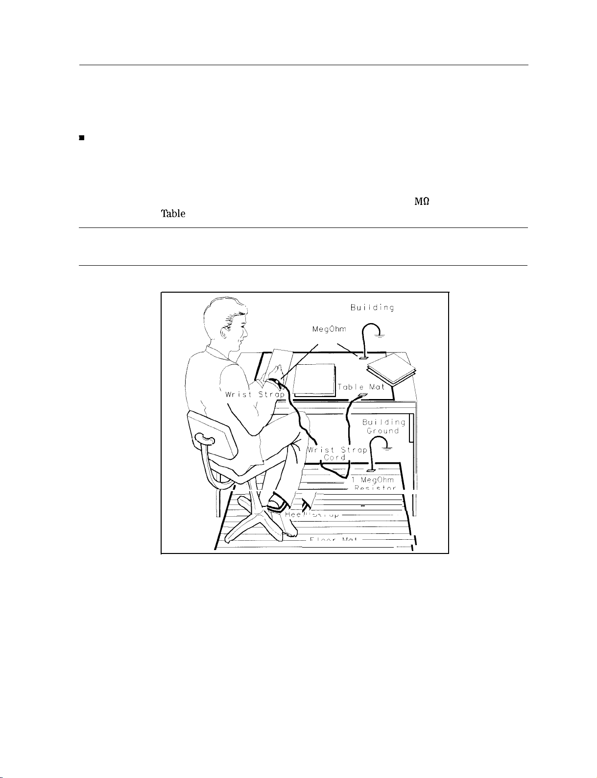
electronic assemblies should be performed at a static-safe work station. Figure l-5 shows an
example of a static-safe work station using two types of ESD protection:
H
Conductive table-mat and wrist-strap combination.
n Conductive floor-mat and heel-strap combination.
Both types, when used together, provide a significant level of ESD protection. Of the two, only
the table-mat and wrist-strap combination provides adequate ESD protection when used alone.
To ensure user safety, the static-safe accessories must provide at least 1 MR of isolation from
ground. Refer to
‘fable
l-4 for information on ordering static-safe accessories.
Warning
These techniques for a static-safe work station should not be used when
working on circuitry with a voltage potential greater than 500 volts.
BUI lding
Ground
1
MegOhm
Resistor
1
/./-xYD
k
q&-
mtiee
I St rap
” -
Floor Mat
-
-\
\Il
AU
-~I
Figure 1-5. Example of a Static-Safe Work Station
Preparing For Use
l-l 1
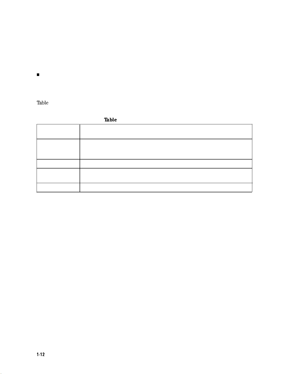
Reducing Damage Caused by ESD
The following suggestions may help reduce ESD damage that occurs during testing and
servicing operations.
n Before connecting any coaxial cable to an spectrum analyzer connector for the first time each
day, momentarily ground the center and outer conductors of the cable.
w
Personnel should be grounded with a resistor-isolated wrist strap before touching the center
pin of any connector and before removing any assembly from the unit.
n Be sure that all instruments are properly earth-grounded to prevent a buildup of static
charge.
Table
l-4 lists static-safe accessories that can be obtained from Hewlett-Packard by using the
HP part numbers shown.
‘Ihble
1-4. Static-Safe Accessories
HP Part
Number
9300-0797
9300-0980
9300-1383
9300-l 169
Description
Set includes: 3M static control mat 0.6 m x 1.2 m (2 ft x 4 ft) and 4.6 cm
(15 ft) ground wire. (The wrist-strap and wrist-strap cord are not included.
They must be ordered separately.)
Wrist-strap cord 1.5 m (5 ft)
Wrist-strap, color black, stainless steel, without cord, has four adjustable
links and a 7 mm post-type connection.
ESD heel-strap (reusable 6 to 12 months).
1.12
Preparing For Use
 Loading...