

Performance Tests and
Adjustments Manual
HP 8566B Spectrum
Analyzer
HEWLETT
F!a
HP
Printed in USA September 1993
PACKARD
Part No. 08566-90168

Notice.
The information contained in this document is subject to change
without notice.
Hewlett-Packard makes no warranty of any kind with regard to this
material, including but not limited to, the implied warranties of
merchantability and fitness for a particular purpose. Hewlett-Packard
shall not be liable for errors contained herein or for incidental
or consequential damages in connection with the furnishing,
performance, or use of this material.
@
Copyright Hewlett-Packard Company 1993
All Rights Reserved. Reproduction, adaptation, or translation without
prior written permission is prohibited, except as allowed under the
copyright laws.
1400 Fountaingrove Parkway, Santa Rosa CA, 95403-1799, USA

Certification
Hewlett-Packard Company certifies that this product met its
published specifications at the time of shipment from the factory.
Hewlett-Packard further certifies that its calibration measurements
are traceable to the United States National Institute of Standards and
Technology, to the extent allowed by the Institute’s calibration facility,
and to the calibration facilities of other International Standards
Organization members.
Warranty
This Hewlett-Packard instrument product is warranted against defects
in material and workmanship for a period of one year from date of
shipment. During the warranty period, Hewlett-Packard Company
will, at its option, either repair or replace products which prove to be
defective.
For warranty service or repair, this product must be returned to a
service facility designated by Hewlett-Packard. Buyer shall prepay
shipping charges to Hewlett-Packard and Hewlett-Packard shall pay
shipping charges to return the product to Buyer. However, Buyer shall
pay all shipping charges, duties, and taxes for products returned to
Hewlett-Packard from another country.
Hewlett-Packard warrants that its software and firmware designated
by Hewlett-Packard for use with an instrument will execute
its programming instructions when properly installed on that
instrument. Hewlett-Packard does not warrant that the operation
of the instrument, or software, or firmware will be uninterrupted or
error-free.
LIMITATION OF WARRANTY
The foregoing warranty shall not apply to defects resulting from
improper or inadequate maintenance by Buyer, Buyer-supplied
software or interfacing, unauthorized modification or misuse,
operation outside of the environmental specifications for the
product, or improper site preparation or maintenance.
NO OTHER WARRANTY IS EXPRESSED OR IMPLIED.
HEWLETT-PACKARD SPECIFICALLY DISCLAIMS THE IMPLIED
WARRANTIES OF MERCHANTABILITY AND FITNESS FOR A
PARTICULAR PURPOSE.
EXCLUSIVE REMEDIES
THE REMEDIES PROVIDED HEREIN ARE BUYER’S SOLE AND
EXCLUSIVE REMEDIES. HEWLETT-PACKARD SHALL NOT BE
LIABLE FOR ANY DIRECT, INDIRECT, SPECIAL, INCIDENTAL, OR
CONSEQUENTIAL DAMAGES, WHETHER BASED ON CONTRACT,
TORT, OR ANY OTHER LEGAL THEORY.
. . .
III

Assistance
Product maintenance agreements and other customer omistance
agreemxmts
Fbr
any assistance, contact your nearest
Service
are available for
Ome.
Hewlett-Rzckard
Hewlett-Fbckard
products.
Sales and
Safety Notes
Caution
Warning
Instruction
Manual
The following safety notes are used throughout this manual.
Familiarize yourself with each of the notes and its meaning before
operating this instrument.
Caution denotes a hazard. It calls attention to a procedure that, if
not correctly performed or adhered to, could result in damage to or
destruction of the instrument. Do not proceed beyond a caution sign
until the indicated conditions are fully understood and met.
Warning denotes a hazard. It calls attention to a procedure
which, if not correctly performed or adhered to, could result in
injury or loss of life. Do not proceed beyond a warning note until
the indicated conditions are fully understood and met.
The instruction manual symbol. The product is marked with this
symbol when it is necessary for the user to refer to the instructions in
the manual.
iv
General Safety Considerations
Warning
Warning
Caution
Before this instrument is switched on, make sure it has been
properly grounded through the protective conductor of the ac
power cable to a socket outlet provided with protective earth
contact.
Any interruption of the protective (grounding) conductor, inside
or outside the instrument, or disconnection of the protective
earth terminal can result in personal injury.
There are many points in the instrument which can, if contacted,
cause personal injury. Be extremely careful.
Any adjustments or service procedures that require operation
of the instrument with protective covers removed should be
performed only by trained service personnel.
Before this instrument is switched on, make sure its primary power
circuitry has been adapted to the voltage of the ac power source.
Failure to set the ac power input to the correct voltage could cause
damage to the instrument when the ac power cable is plugged in.
V
How to Use This Manual
This manual uses the
following
conventions:
HP 8566B Documentation Description
HP 8566B
HP 8566B Operating
and Programming
Installation
and Verification
Manual
Manual
Front-Panel Ke
Screen Text
Included with the HP Model 8566B spectrum analyzer are manuals:
The Installation and Verification Manual, the Operating and
Programming Manual, and the Performance Tests and Adjustments
Manual.
HP part number 08566-90169
Contents: General information, installation, specifications,
characteristics, and operation verification.
HP part number 08566-90040
Contents: Manual and remote operation, including complete syntax
and command description.
pocket-sized Quick Reference Guide, HP part number
r) This represents a key physically located on the
instrument.
This indicates text displayed on the instrument’s
screen.
Accopanying
this manual is the seperate,
5955-8970.
HP 8566B
Performance
Tests and
Adjustments Manual
HP 8566B RF
Section
Troubleshooting
Repair
Manual
HP 8566B IF-Display
Section
Troubleshooting
Repair
Manual
and
and
HP part number 08566-90168
Contents: Electrical performance tests and adjustment procedures.
HP part number 08566-90210
Contents: RF section service information.
HP part number 08566-90085
Contents: IF-Display section service information.
vi

Contents
1. General Information
Introduction
Instruments Covered by this Manual
Operation Verification
Option 462 Instruments
Option 857 Instruments
2. Performance Tests
Introduction
Verification of Specifications
Calibration Cycle
Equipment Required
Performance Test Record
1. Center Frequency Readout Accuracy Test
2. Frequency Span Accuracy Test
3. Resolution Bandwidth Accuracy Test
4. Resolution Bandwidth Selectivity Test
5. Resolution Bandwidth Switching Uncertainty Test
6. Log
7. IF Gain Uncertainty Test
8. Amplitude Fidelity Test
9. Calibrator Amplitude Accuracy Test
10. Frequency Response Test
11. Sweep Time Accuracy Test
12. Noise Sidebands Test
13. Line-Related Sidebands Test
14. Average Noise Level Test
15. Residual Responses Test
16. Harmonic and Intermodulation Distortion Test
17. Image, Multiple, and Out of Band Responses Test
18. Gain Compression Test
19. 1st LO Output Amplitude Test
20. Sweep + Tune Out Accuracy Test
21. Fast Sweep Time Accuracy Test (~20 ms)
22. Frequency Reference Error Test
‘Iable
2-24. Performance Test Record
Test 1. Center Frequency Readout Accuracy
Test 2. Frequency Span Accuracy Test
Test 3. Resolution Bandwidth Accuracy Test
Test 4. Resolution Bandwidth Selectivity
Test 5. Resolution Bandwidth Switching Uncertainty .
Test 6. Log
Test 7. IF Gain Uncertainty
Test 8. Amplitude Fidelity
Test 9. Calibrator Amplitude Accuracy
Test 10. Frequency Response Test
.....................
.........
................
...............
...............
.....................
.............
..................
................
..............
.........
Scale
Switching Uncertainty Test
............
............
...........
..........
.............
..........
...........
............
............
.........
........
..........
........
Scale
Switching Uncertainty Test
.............
.............
........
..........
....
......
......
......
.......
.......
....
.....
.....
.......
.....
.
l-l
l-2
l-2
l-2
l-2
2-l
2-l
2-2
2-3
2-3
2-4
2-8
2-12
2-14
2-17
2-19
2-21
2-27
2-31
2-32
2-46
2-49
2-53
2-58
2-61
2-65
2-73
2-77
2-81
2-82
2-84
2-87
2-89
2-90
2-91
2-92
2-93
2-94
2-95
2-96
2-99
2-100
2-101
Contents-l

Test 11. Sweep Time Accuracy
Test 12. Noise Sidebands Test
Test 13. Line-Related Sidebands
Test 14. Average Noise Level
Test 15. Residual Responses
...........
............
...........
............
.............
Test 16. Harmonic And Intermodulation Distortion . . 2-108
Test 17. Image, Multiple, and Out-of-Band Responses . 2-109
Test 18. Gain Compression
Test 19. 1st LO Output Amplitude
Test 20. Sweep + Tune Out Accuracy
.............
..........
........
Test 21. Fast Sweep Time Accuracy (< 20 ms)
Test 22. Frequency Reference Error Test
3. Adjustments
Introduction
Safety Considerations
Equipment Required
Adjustment Tools
Factory-Selected Components
Related Adjustments
.....................
.................
.................
...................
.............
.................
Location of Test Points and Adjustments
1. Low-Voltage Power Supply Adjustments
.......
........
......
2. High-Voltage Adjustment (SN 3001A and Below) . .
2. High-Voltage Adjustment (SN 3004A and Above) . .
3. Preliminary Display Adjustments (SN 3001A and
Below)
.....................
3. Preliminary Display Adjustments (SN 3004A and
4.
Above)
Final
.....................
Display Adjustments (SN 3001A and Below)
4. Final Display Adjustments (SN 3004A and Above)
5. Log Amplifier Adjustments
6. Video Processor Adjustments
7. 3 MHz Bandwidth Filter Adjustments
8. 21.4 MHz Bandwidth Filter Adjustments
9. 3 dB Bandwidth Adjustments
............
...........
.......
.....
..........
10. Step Gain and 18.4 MHz Local Oscillator
Adjustments
11. Down/Up Converter Adjustments
..................
........
12. 10 MHz Standard Adjustment (SN 2637A and
Below)
.....................
12. 10 MHz Standard Adjustment (SN 2728A and
Above)
.....................
13. Sweep, DAC, and Main Coil Driver Adjustments . .
14. 100 MHz VCXO Adjustments
15. MN Loop Adjustments
16.
YT.0
Loop Adjustments
17.
20/30
Loop Phase Lock Adjustments
18. RF Module Phase Lock Adjustments
19. CAL Output Adjustment
20. Last Converter Adjustments
2 1. Frequency Response Adjustments
22. Analog-To-Digital Converter Adjustments
23. Track and Hold Adjustments
24. Digital Storage Display Adjustments
Low-Noise DC Supply
................
...........
.............
.............
.......
.......
.............
...........
........
.....
............
.......
....
.
.
2-103
2-104
2-105
2-106
2-107
2-l 11
2-112
2-113
2-l 14
2-115
3-l
3-2
3-2
3-2
3-3
3-3
3-3
3-25
3-31
3-41
3-48
3-56
3-63
3-65
3-69
3-73
3-76
3-82
3-89
3-94
3-100
3-104
3-108
3-113
3-126
3-132
3-135
3-146
3-160
3-166
3-169
3-174
3-206
3-209
3-212
3-218
Contents-2

Crystal Filter Bypass Network Configuration . . . . .
4.
Option 462
Introduction . . . . . . . . . . . . . . . . . . . . .
3. 6 dB Resolution Bandwidth Accuracy Test . . . . .
3. Impulse and Resolution Bandwidth Accuracy Test
4. 6 dB Resolution Bandwidth Selectivity Test . . . .
4. Impulse and Resolution Bandwidth Selectivity Test .
5. Impulse and Resolution Bandwidth Switching
Uncertainty Test . . . . . . . . . . . . . . . .
Test 3. 6 dB Resolution Bandwidth Accuracy Test (p/o
lhble
2-24, Performance Test Record) . . . . . . .
Test 3. Impulse and Resolution Bandwidth Accuracy
Test (p/o
‘Ihble
2-24, Performance Test Record)
Test 4. 6 dB Resolution Bandwidth Selectivity (p/o
Table 2-24, Performance Test Record) . . . . . . .
Test 4. Impulse and Resolution Bandwidth Selectivity
(p/o
Table
2-24, Performance Test Record) . . . . .
Test 5. Impulse and Resolution Bandwidth Switching
Uncertainty (p/o
‘Ihble
2-24, Performace Test
Record) . . . . . . . . . . . . . . . . . . . . .
9. 6 dB Resolution Bandwidth Adjustments . . . . .
9. Impulse Bandwidth Adjustments . . . . . . . . .
Option 857
5.
Introduction . . . . . . . . . . . . . . . . . . . . .
8. Option 857 Amplitude Fidelity Performance Test . .
Performance Test Record . . . . . . . . . . . . . . .
Test 8. Option 857 Amplitude Fidelity . . . . . . . .
. .
.
3-219
4-l
4-2
4-4
4-10
4-13
4-16
4-18
4-19
4-21
4-22
4-23
4-24
4-27
5-l
5-2
5-6
5-7
Major Assembly and Component Locations
6.
IF-Display Section Figure Index . . . . . . . . . . . .
RF Section Figure Index . . . . . . . . . . . . . . .
6-l
6-2
Contents3
Figures
l-l. Service Accessories, HP Part Number 08566-60001
2-l. Center Frequency Test Setup
2-2. Center Frequency Accuracy Measurement
2-3. Narrow Span Test Setup
2-4. Wide Span Test Setup
2-5. Resolution Bandwidth Measurement
2-6. 60 dB Bandwidth Measurement
2-7. Bandwidth Switching Uncertainty Measurement
2-8. Log
2-9. IF Gain Uncertainty Test Setup
2-10. IF Gain Uncertainty Measurement
2-l 1. Amplitude Fidelity Test Setup
2-12. Amplitude Fidelity Measurement
2-13. Calibrator Amplitude Accuracy Test Setup
2-14. Frequency Response Test Setup (100 Hz to 100
2-15. Frequency Response Measurement (1
2-16. Frequency Response Test Setup (100
2-17. Frequency Response Measurement (100
2-18. Frequency Response Measurement (4 MHz to 60 MHz)
2-19. Frequency Response Test Setup (60 MHz to 2.5
2-20. Frequency Response Measurement (60 MHz to 2.5
2-21. Sweep Time Accuracy Test Setup
2-22. Noise Sidebands Test Setup
2-23. Noise Sidebands Measurement
2-24. Line Related Sidebands Test Setup
2-25. Line-Related Sidebands Measurement
2-26. Average Noise Level Measurement
2-27. Residual Responses Measurement
2-28. Harmonic Distortion Test Setup
2-29. Intermodulation Distortion
2-30. Third Order Intermodulation Products
2-31. Image, Multiple, and Out-of-Band Responses Test Setup
2-32. Gain Compression Test Setup
2-33. 1st LO Output Amplitude Test Setup
2-34. Sweep + Tune Out Accuracy Test Setup
2-35. Fast Sweep Time Accuracy (~20 ms) Test Setup
2-36. Fast Sweep Time Measurement (~20 ms)
2-37. Frequency Reference Test Setup
3-l. Low-Voltage Power Supply Adjustments Setup
3-2. IF-Display Section Adjustments (SN 3001A and Below)
3-3. IF-Display Section Adjustments (SN 3004A and Above)
3-4. Location of RF Section Low-Voltage Adjustments
3-5. High Voltage Adjustment Setup
3-6. Location of High Voltage Adjustments
3-7. Location of Label and Test Point
Scale
Switching Uncertainty Measurement
to22GHz)
...................
...............
................
............
......
.........
...........
...........
..........
............
..........
......
kHz
to 100
kHz
to 60 MHz)
kHz
to 4 MHz)
..........
.............
............
..........
........
..........
..........
...........
Test
Setup
............
........
........
.........
.......
.......
...........
...........
........
...........
. .
...
....
kHz)
kHz)
GHz,
2
GHz)
....
....
...
.
.
l-9
2-4
2-6
2-8
2-10
2-13
2-15
2-18
2-20
2-21
2-23
2-27
2-29
2-31
2-33
2-35
2-36
2-37
2-38
2-39
2-41
2-46
2-50
2-51
2-53
2-55
2-59
2-62
2-66
2-69
2-71
2-73
2-77
2-81
2-82
2-84
2-85
2-88
3-25
3-26
3-27
3-29
3-32
3-33
3-34
Contents-4
3-8. Location of
AlA
Components ...........
3-9. CRT Cut-Off Voltage
3-10. Waveform at
3-l 1. Discharging the CRT Post-Accelerator Cable
3-12. High Voltage Adjustment Setup
3-13. Location of High Voltage Adjustments
3-14. Location of
3-15. Discharging the CRT Post-Accelerator Cable
3-16. Preliminary Display Adjustments Setup
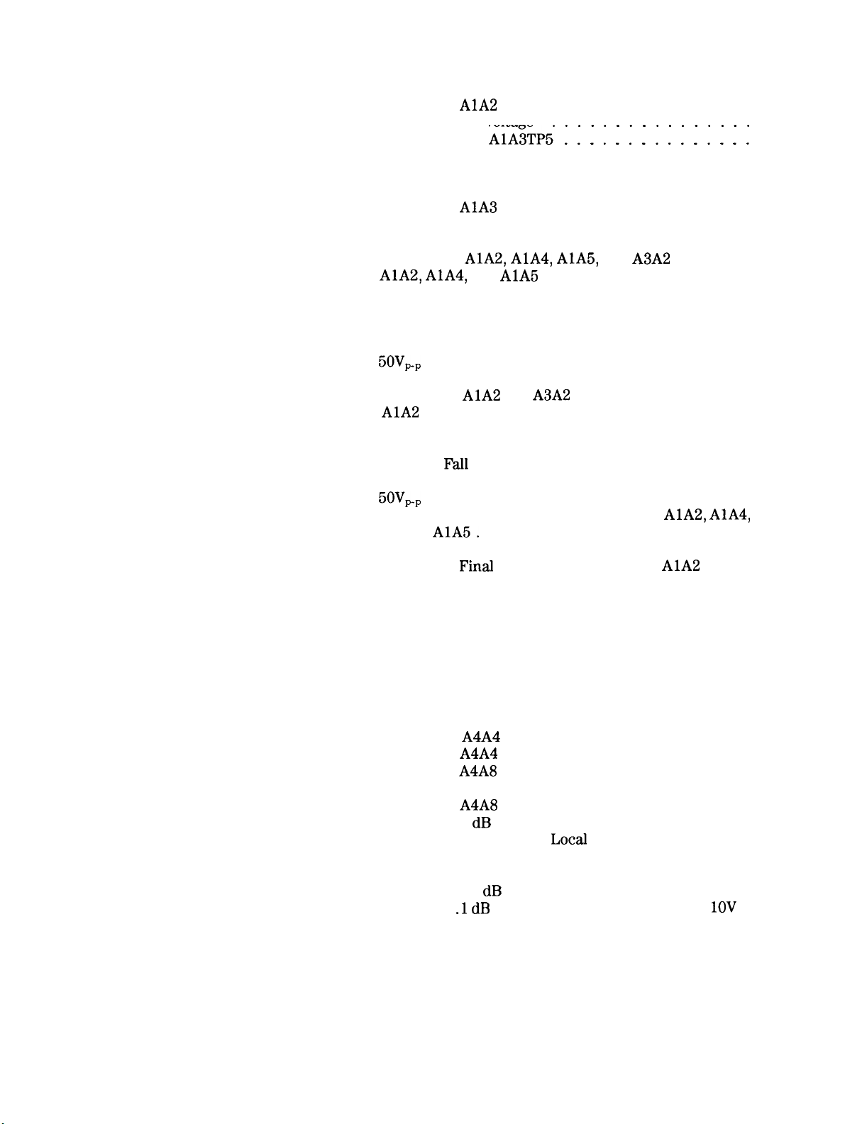
3-17. Location of AlA2, AlA4, AlA5, and
3-18. AlA2, AlA4, and
AlA3TP5’ : : : : : : : : : : : : 1 : :
...........
........
AlA
Label and Test Point
........
.......
A3A2
AlA
Adjustment Locations ....
.....
.....
.....
3-19. X+ and X- Waveforms ...............
3-20. Composite X Deflection Waveform
..........
3-21. Rise and Fall Times and Overshoot Adjustment
Waveform
...................
3-22. 5OV,, Signal ....................
3-23. Preliminary Display Adjustments Setup
3-24. Location of
3-25.
AlA
Adjustment Locations
AlA
and
A3A2
............
.............
.......
3-26. X+ and X- Waveforms ...............
3-27. Composite X Deflection Waveform
3-28. Rise and
Fall
Waveform
Times and Overshoot Adjustment
...................
..........
3-29. 5OV,, Signal ....................
3-30. Location of Final Display Adjustments on AlA2,
and
AlA5.
3-31. Final Display Adjustments Setup
3-32. Location of
3-33. Log Amplifier Adjustments Setup
3-34. Location of Log Amplifier Adjustments
3-35. Video Processor Adjustments Setup
3-36. Location of Video Processor Adjustments
...................
...........
Final
Display Adjustments on
AlA
..........
........
.........
.......
3-37. 3 MHz Bandwidth Filter Adjustments Setup
AlA4,
...
.....
3-38. Location of Center, Symmetry, and 10 Hz Amplitude
Adjustments
3-39. Location of 3 MHz Peak Adjustments
..................
.........
3-40. 21.4 MHz Bandwidth Filter Adjustments Setup ....
3-41. Location of
3-42. Location of
3-43. Location of
Adjustments
3-44. Location of
A4A4
21.4 MHz LC Filter Adjustments . .
A4A4
21.4 MHz Crystal Filter Adjustments
A4A8
21.4 MHz LC Filter and Attenuation
..................
A4A8
21.4 MHz Crystal Filter Adjustments
3-45. Location of 3 dB Bandwidth Adjustments ......
3-46. Step Gain and 18.4 MHz
Setup
......................
3-47. Location of IF Gain Adjustment
3-48. Location of 10 dB Gain Step Adjustments
3-49. Location of .l dB Gain Step, 18.4 MHz LO, and +
Adjustments
..................
3-50. Down/Up Converter Adjustments Setup
3-51. Location of Down/Up Converter Adjustments
3-52. 10 MHz Frequency Standard Adjustments Setup
3-53. Location of 10 MHz Standard Adjustments
3-54. 10 MHz Frequency Standard Adjustments Setup
3-55. Location of 10 MHz Standard Adjustments
Local
Oscillator Adjustments
...........
.......
......
1OV
.....
...
......
...
......
3-36
3-37
3-38
3-40
3-42
3-43
3-44
3-47
3-49
3-50
3-50
3-51
3-52
3-53
3-54
3-57
3-58
3-58
3-59
3-60
3-60
3-62
3-64
3-65
3-66
3-69
3-70
3-73
3-74
3-76
3-78
3-80
3-82
3-83
3-84
3-85
3-86
3-90
3-94
3-96
3-97
3-98
3-100
3-101
3-105
3-107
3-109
3-112
Contents-5
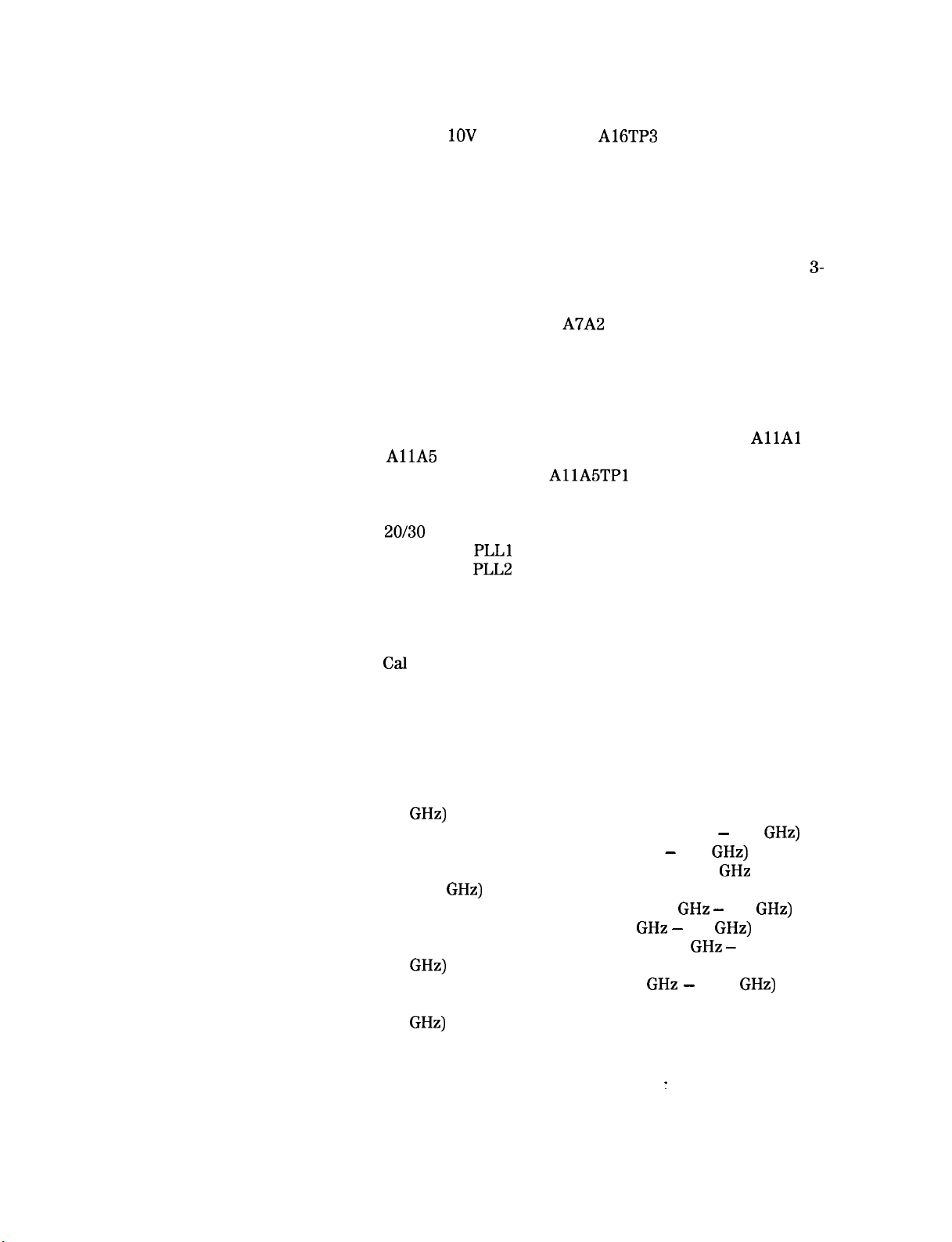
3-56. Sweep and DAC Adjustments Setup
3-57. OV to +
1OV
Sweep Ramp at
A16TP3
.........
.........
3-58. Location of Sweep and DAC Adjustments
.......
3-114
3-115
3-116
3-59. Properly Adjusted DC Levels Between Sweep Ramps . 3-117
3-60. Improperly Adjusted DC Levels Between Sweep Ramps
3-61. YTO Main Coil Driver Adjustments Setup
3-62. Location of YTO Main Coil Driver Adjustments
.......
....
3-117
3-120
3-121
3-63. YTO Main Coil Driver Adjustments Setup (Alternate
3-
Procedure)
3-64. 100 MHz VCXO Adjustment Setup
3-65. Location of 100 MHz VCXO Adjustments
3-66. Typical Tuning Range of
3-67. M/N Loop Adjustment Setup
3-68. Location of PLL Adjustments
3-69. YTO Loop Adjustment Setup
3-70. Location of Assemblies, Cables, and Test Points
3-71. All YTO Loop Service Position
3-72. Typical YTO Loop Swept Frequency Response at
3-73.
AllA
Adjustment Locations
3-74. Sampler Waveform at
...................
..........
.......
A7A2
100 MHz VCXO
....
.............
............
............
....
...........
AllAl
............
AllA5TPl
..........
3-75. 30 MHz YTO Loop Sampler Response at AllJ5 IF OUT
3-76. Tuning the IF OUT Fundamental
3-77.
20/30
PLL Adjustment Setup
3-78. Location of
3-79. Location of
PLLl
Adjustments
PLL2
Adjustments
3-80. Location of PLL3 Adjustments
3-81. RF Module Phase Lock Adjustments Setup
3-82. Location of RF Module Phase Lock Adjustments
3-83. A Sampler Balance Adjustment Waveform
3-84.
Cal
Output Adjustment Setup
3-85. Location of CAL OUTPUT Adjustment
3-86. CAL OUTPUT Harmonics
..............
3-87. Last Converter Adjustments Setup
3-88. Location of Last Converter Adjustments
..........
............
............
............
............
......
...
......
............
........
..........
.......
122
3-126
3-127
3-128
3-132
3-133
3-136
3-136
3-137
3-139
3-140
3-142
3-143
3-144
3-147
3-149
3-154
3-156
3-161
3-161
3-164
3-166
3-167
3-168
3-170
3-171
3-89. Frequency Response Preliminary Adjustments Setup . 3-176
3-90. Location of Frequency Response Adjustments
....
3-177
3-91. Frequency Response Adjustments Setup (10 MHz to 2.5
GHz)
......................
3-92. Typical Coarse Frequency Response (10 MHz - 2.5
3-93. Typical Frequency Response (10 MHz - 2.5
3-94. Frequency Response Adjustments Setup (2.0
22.0
GHz)
....................
3-95. Typical Coarse Frequency Response (2
3-96. Typical Frequency Response (2.0
GHz -
3-97. Typical Coarse Frequency Response (5.8
GHz)
3-98. Typical Frequency Response (5.8
......................
GHz -
GHz -
5.8
GHz -
12.5
GHz)
GHz
5.8
GHz)
12.5
GHz)
to
...
GHz)
...
3-179
GHz)
3-181
3-182
3-185
3-187
3-188
3-191
. . 3-193
3-99. Frequency Response Adjustments Setup (18.6 to 325
GHz)
......................
3-100. Analog-To-Digital Converter Adjustments Setup
....
3-204
3-206
3-101. Location of Analog-To-Digital Converter Adjustments . 3-208
3-102. Track and Hold Adjustments Setup
3-103. Location of Track and Hold Adjustments
3-104. Digital Storage Display Adjustments Setup
........
:
.......
......
3-105. Location of Digital Storage Display Adjustments
...
3-209
3-210
3-212
3-213
Contents-6

3-106. Sample and Hold Balance Adjustment Waveforms
3-107. Waveform Before Adjustment
3-108. Low-Noise DC Supply
................
............
3-109. Crystal Filter Bypass Network Configurations
...
.....
4-l. Resolution Bandwidth Measurement .........
4-2. Impulse Bandwidth Test Setup
4-3. 6 dB Resolution Bandwidth Measurement
............
......
4-4. 60 dB Bandwidth Measurement ...........
4-5. 60 dB Bandwidth Measurement ...........
4-6. Bandwidth Switching Uncertainty Measurement
4-7. Location of Bandwidth Adjustments
4-8. Location of Bandwidth Adjustments
.........
.........
5-l. Option 857 Amplitude Fidelity Test Setup
6-l. RF Section, Top View
6-2. RF Section, Front View
6-3. RF Section, Bottom View
................
...............
..............
6-4. IF Section, Top View (SN 3001A and Below)
6-5. IF Section,
‘Ibp
View (SN 3004A and Above)
...
......
.....
.....
6-6. IF Section, Front View ...............
6-7. IF Section, Bottom View
..............
3-215
3-215
3-218
3-219
4-3
4-4
4-8
4-11
4-14
4-17
4-25
4-28
5-2
6-3
6-4
6-5
6-6
6-7
6-8
6-9
Contents-7
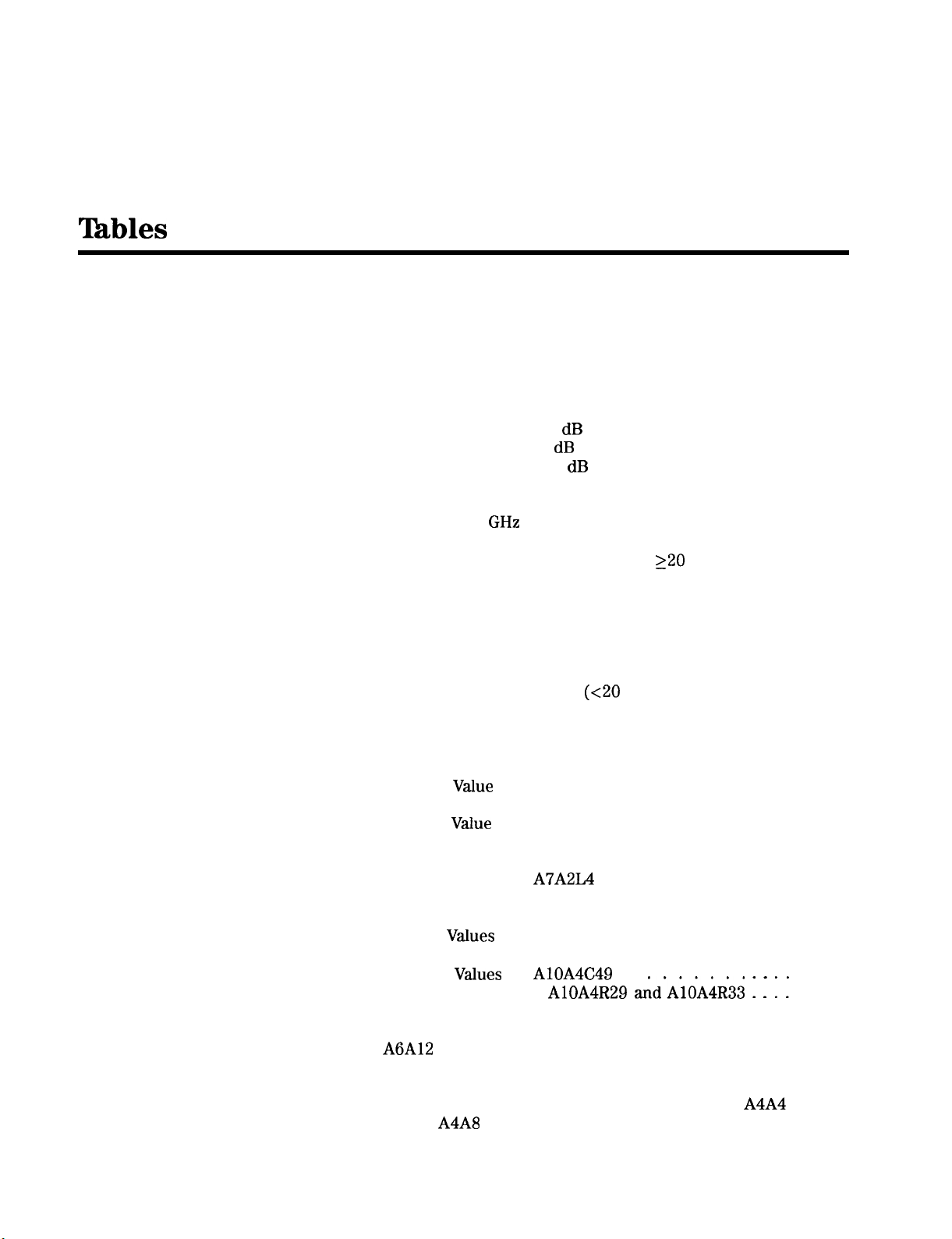
!Ihbles
2-l. Performance Test Cross-Reference ..........
2-2. Center Frequency Readout Accuracy .........
2-3. Narrow Span Accuracy
2-4. Wide Span Accuracy
2-5. Bandwidth Accuracy
2-6. Resolution Bandwidth Selectivity
2-7. Bandwidth Switching Uncertainty ..........
2-8. Log Scale Switching Uncertainty
2-9. IF Gain Uncertainty, 10 dB Steps ..........
2-10. IF Gain Uncertainty, 2 dB Steps
2-l 1. IF Gain Uncertainty, 0.1 dB Steps ..........
2-12. Log Scale Fidelity
2-13. Linear Amplitude Fidelity
2-14. 100 Hz to 2.5
2-15. Frequency Response (Flatness)
2-16. Sweep Time Accuracy, Sweep Times
2-17. Sweep Time Accuracy
2-18. Average Noise Level
2-19. TO1 Measurement Settings
2-20. Image and Out-of-Band Response
2-2 1. Multiple Responses
2-22. Sweep + Tune Out Accuracy ............
2-23. Fast Sweep Time Accuracy
2-24. Frequency Response (Flatness)
3-l. Adjustment Cross Reference .............
3-2. Adjustable Components
3-3. Factory-Selected Components
3-4. Standard
3-5. Standard Value Replacement 0.125 Resistors
3-6. Standard
3-5. Initial Adjustment Positions
3-6. Initial Adjustment Positions
3-7. Standard Values for
3-8. Limits for 100 MHz Harmonics
3-9. Selection Chart for Attenuator Resistors
3-10. Resistor
3-11. Power Level of Fundamental Signal
3-12. Standard
3-13. Standard Values for
3-14. Frequency Bands
3-15. Preselector Delay Compensation DAC Values
3-16.
A6A12
3-17. Parts for Low-Noise DC Supply
3-18. Crystal Filter Bypass Network Configuration for
YTX Driver Assembly Factory-Select Capacitor
Values
and
A4A8
GHz
Frequency Band
Value
Replacement Capacitors
Value
Replacement 0.5 Resistors
Values
Values
...................
for
..................
.....................
(21.4 MHz)
...............
................
................
..........
...........
...........
.................
..............
.........
...........
220
...............
................
.............
..........
.................
(~20
ms)
.........
...........
...............
............
.............
.............
A7A2L4
AlOA4C49
AlOA4R29
............
............
.........
and’AliA4R33 : : :
...........
..............
.....
ms
.......
.....
......
.......
.....
A4A4
:
2-2
2-7
2-9
2-11
2-13
2-16
2-18
2-20
2-23
2-24
2-25
2-29
2-30
2-37
2-45
2-48
2-48
2-60
2-72
2-75
2-76
2-83
2-86
2-102
3-4
3-5
3-13
3-20
3-21
3-23
3-63
3-66
3-128
3-130
3-130
3-131
3-144
3-157
3-158
3-174
3-202
3-203
3-218
3-219
Contents-8

3-19. Crystal Filter Bypass Network Configuration for
(3MHz)
. . . . . . . . . . . . . . . . . . . . .
A4A7
4-l. 6 dB Resolution Bandwidth Accuracy . . . . . . . .
4-2. Impulse Bandwidth Accuracy . . . . . . . . . . . .
4-3. 6 dB Resolution Bandwidth Accuracy . . . . . . . .
4-4. 6 dB Resolution Bandwidth Selectivity . . . . . . . .
4-5. Impulse and Resolution Bandwidth Selectivity . . . .
4-6. Bandwidth Switching Uncertainty . . . . . . . . . .
5-l. Log Amplitude Fidelity (10 Hz RBW; Option 857) . . .
5-2. Log Amplitude Fidelity (10
kHz
RBW; Option 857)
5-3. Linear Amplitude Fidelity . . . . . . . . . . . . . .
. .
3-219
4-3
4-9
4-9
4-12
4-15
4-17
5-4
5-5
5-5
Contents-9

General Information
1
Introduction
Warning
This HP 8566B Tests and Adjustments Manual contains two main
sections: Performance Tests and Adjustments Procedures. This
chapter lists the required test equipment for both sections. The
performance tests provided should be performed for the following
reasons:
w
If the test equipment for the Operation Verification Program is not
available.
w
If the instrument does not pass all of the Operation Verification
tests.
n
For complete verification of specifications not covered by the
Operation Verification program.
The adjustment procedures should be performed for the following
reasons:
w
If the results of a performance test are not within the specifications.
w
After the replacement of a part or component that affects electrical
performance.
The adjustment procedures require access to the interior of the
instrument and therefore should only be performed by qualified
service personnel. There are voltages at many points in the
instrument which can, if contacted, cause personal injury. Be
extremely careful. Adjustments should be performed only by
trained service personnel.
Power is still applied to this instrument with the LINE switch in
STANDBY. There is no OFF position on the LINE switch. Before
removing or installing any assembly or printed circuit board,
remove the power cord from the rear of both instruments and
wait for the MAINS indicators (red
Capacitors inside the instrument may still be charged even if the
instrument has been disconnected from its source of power. Use a
non-metallic tuning tool whenever possible.
LEDs)
to go completely out.
General Information
1-l
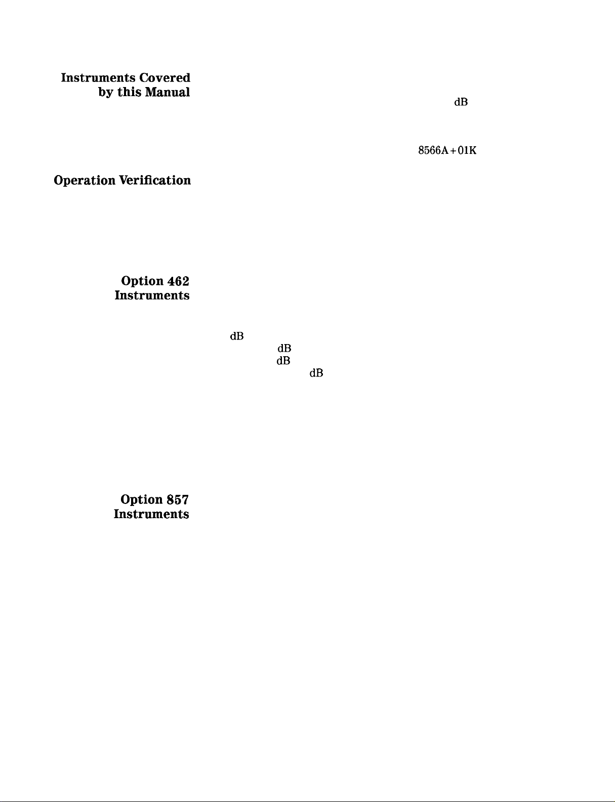
Instruments
by
this Manual
Covered
This manual contains procedures for testing and adjusting HP
8566B spectrum analyzers, including those with Option 400 (400 Hz
operation), Option 462 (impulse bandwidths and 6 dB bandwidths),
and Option 857 installed. The procedures in this manual can also
be used to adjust HP 8566A spectrum analyzers that have been
converted into HP 8566B spectrum analyzers through the installation
of an HP 8566AB Retrofit Kit (formerly HP 8566A+OlK Retrofit Kit).
Operation Verification
Option 462
Instruments
A high confidence level in the instrument’s operation can be achieved
by running only the Operation Verification Program, since it tests
most of the instrument’s specifications. It is recommended that the
Operation Verification Program be used for incoming inspection and
after repairs, since it requires much less time and test equipment.
A description of the program can be found in the Installation and
Verification manual.
Option 462 instruments require that the performance tests and
adjustment procedures listed below be performed instead of their
standard versions included in chapters two and three. Information on
Option 462 versions is located in Chapter 4, Option 462.
6 dB Bandwidths:
Test 3, 6 dB Resolution Bandwidth Accuracy Test
Test 4, 6 dB Resolution Selectivity Test
Adjustment 9, 6 dB Bandwidth Adjustment Procedure
Impulse Bandwidths:
Test 3, Impulse Resolution Bandwidth Accuracy Test
Test 4, Impulse and Resolution Selectivity Test
Test 5, Impulse and Resolution Bandwidth
Switching Uncertainty Test
Adjustment 9, Impulse Bandwidth Adjustment Procedure
Option 867
Instruments
1-2 General Information
Option 857 instruments are used in EMC receiver applications.
Information on Option 857 is located in Chapter 5, Option 857.
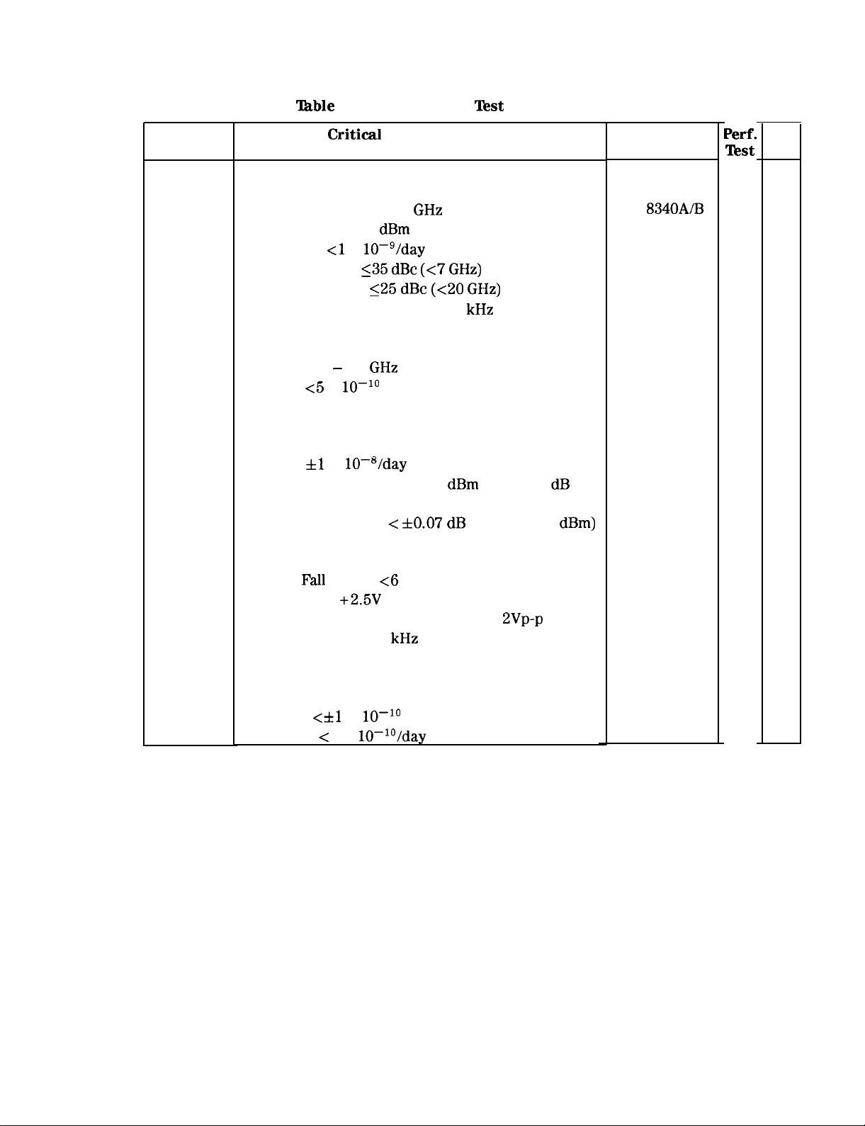
‘lhble
l-l. Recommended Test Equipment (1 of 6)
Instrumenl
SIGNAL
SOURCES
Synthesized
Sweeper
Synthesized
Signal
Generator
Frequency
Synthesizer
Critical Specifications for
Equipment Substitution
Frequency: 10 MHz to 22
Output Power: + 10
Aging Rate: ~1 x
10mg/day
Spurious Signals: 135
125
Amplitude Modulation: dc to 100
GHz
dBm
maximum (leveled)
dBc
(~7
GHz)
dBc (<20 GHz)
kHz
Leveling: Internal, External Power Meter
Frequency: 2 - 18
Stability: ~5 x
GHz
lo-lo
Frequency: 200 Hz to 80 MHz
Stability: fl x IO-“/day
Amplitude Range: + 13 to -86
dBm
with 0.01
resolution
Attenuator Accuracy: <
f0.07 dB
(+ 13 to -47
dB
dBm)
Recommended
Model
HP
8340A/B
HP 8672A
HP 3335A
Perf.
Test
X
X
X
Adj.
X
X
X
Pulse
Generator
Function
Generator
Frequency
Standard
Pulse Width: 10 nsec to 250 nsec
Rise and
Output Level:
Output: Sine Wave and Triangle Wave,
Range: 100 Hz to 500
(2 required)
Fall
Times: ~6 ns
+2.5V
BVp-p
kHz
(Sweep Function Available)
Output: 1, 2, 5, or 10 MHz
Accuracy:
Aging Rate: < 1 x
<hl
x
lo-lo
lo-lo/day
HP 8116A
HP 3312A
HP 5061B
X
X
X
X
X
General Information 1-3
Instrument
ANALYZERS
Spectrum
Analyzer
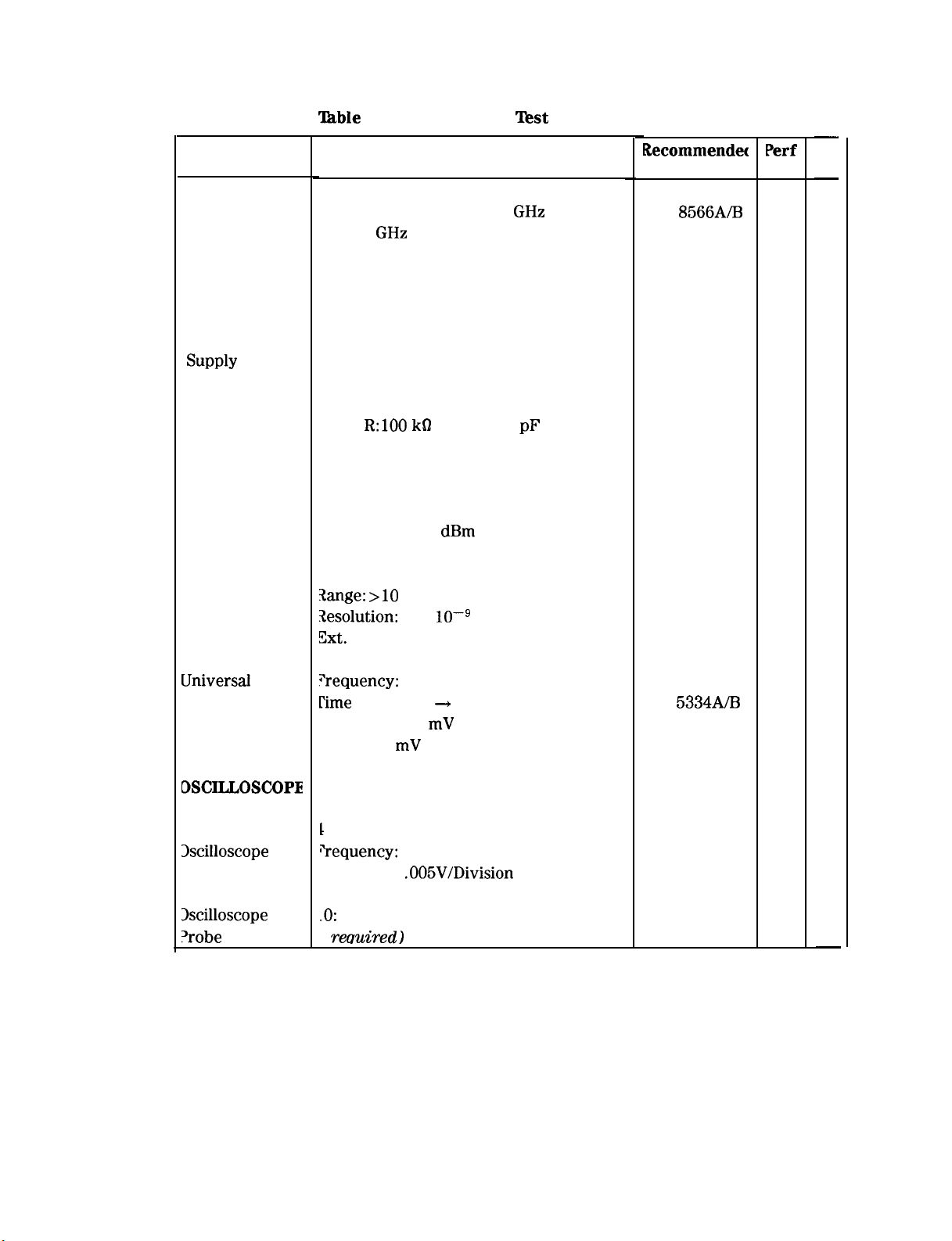
‘able
l-l. Recommended Test Equipment (2 of 6)
Critical Specifications for
Equipment Substitution
Frequency: 100 Hz to 2.5
2 to 22
GHz
Preselected
GHz
Recommenda
Model
HP
8566A/B
Perf
Test
X
-
Adj
-
X
Active Probe
Probe Power
SUPPIY
High Frequency
Active Probe
COUNTERS
Frequency
Counter
Electronic
Counter
UniversaI
Counter
Resistive Divider for measuring fast
transition signals
For use with HP 10020A
Bandwidth: 5 Hz to 500 MHz
Input
R:lOO k62
Input C: 3
pF
Frequency: 20 MHz to 400 MHz
Sensitivity: -30
dBm
HP-IB Compatible
bnge: >lO
Xesolution:
Zxt.
Time Base: 1, 2, 5, or 10 MHz
+equency:
Time
Interval A + B: 100 ns to 200s
MHz
2 x
10Wg
gate time
dc to 100 MHz
sensitivity: 50 mV rms
Eange: 30 mV to 5V p-p
HP 10020A
HP 1122A
HP 41800A
HP 5343A
HP 5345A
HP 5316B
HP
5334AB
X
X
X
X
X
X
DSCILLOSCOPE
Digitizing
3scilloscope
1scilloscope
‘robe
1-4 General Information
1
Channel
“requency: 100 MHz
sensitivity:
.O:
1 Divider, compatible with oscilloscope
2
reauired 1
.005V/Division
HP 54501A
HP 10432A
X
X
-
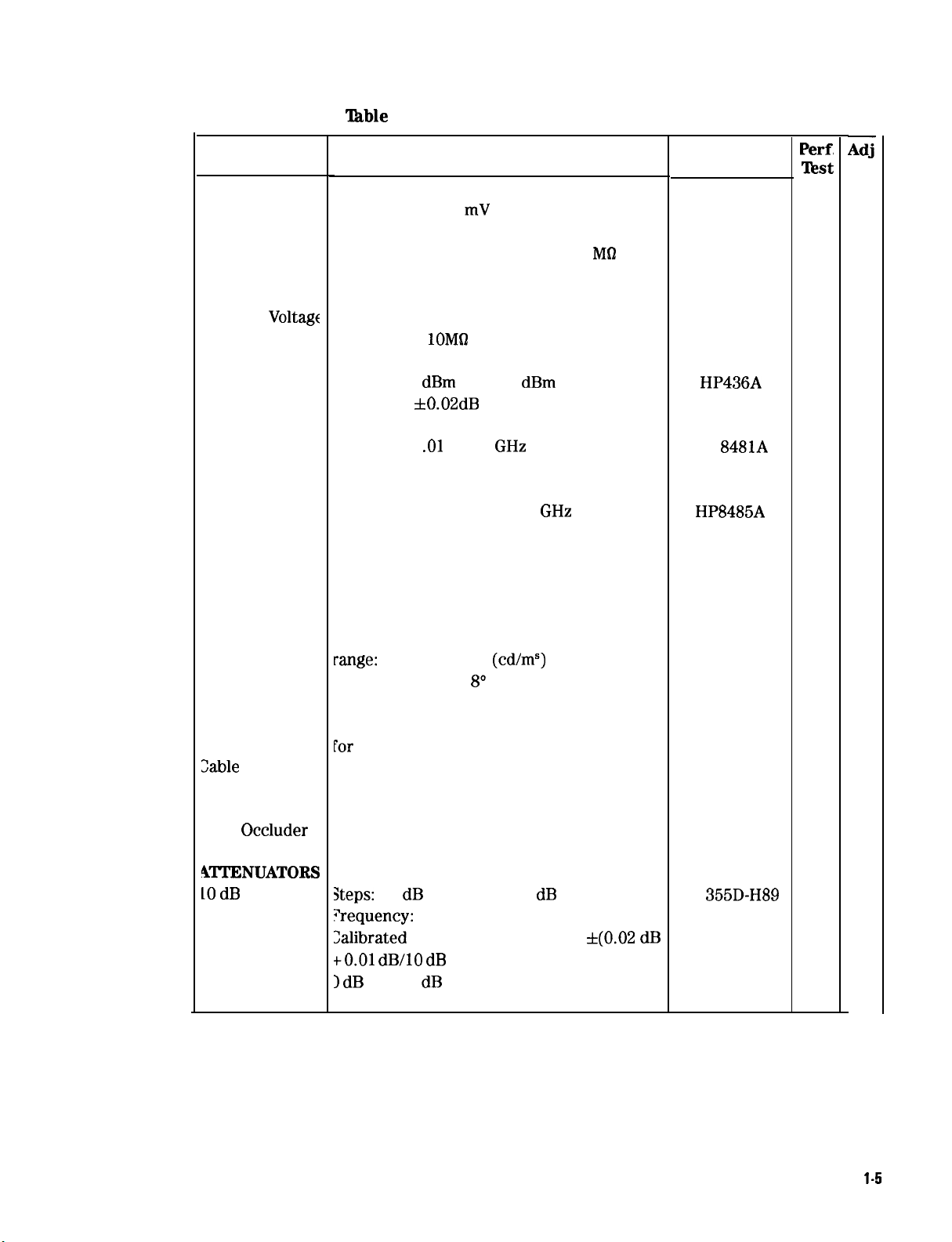
‘Ihble
l-l. Recommended Test Equipment (3 of 6)
Instrument
METERS
Digital
Voltmeter
DC High
Voltage
Probe
Power Meter
Power Sensor
Power Sensor
Digital
Photometer
Critical Specifications for
Equipment Substitution
Resolution: fO.l
mV
Range: 0 Vdc to 100 Vdc
Input Impedance 100 V Range: 10
M62
HP-IB Compatible
1000: 1 Divider
Impedance:
Range: -20
lOM62
dBm
to + 10
dBm
Accuracy: f0.02dB
Frequency:
.Ol
to 18
GHz
Compatible with HP 436A Power Meter
Frequency: 50 MHz to 26.5
GHz
Compatible with HP 436A Power Meter
Recommended
Model
HP 3456A
or
HP 3455A
HP 34111A
HP436A
HP
8481A
HP8485A
Tektronix J-16
Option 02
Perf,
Test
X
X
X
Adj
X
X
X
X
X
Photometer
Probe
Interconnect
Zable
Photometer
Light Occluder
YITENUATORS
10 dB
Step
4ttenuator
for Tektronix J-16
range:
1 to 100 NITS
acceptance angle:
(cd/m”)
8”
spectral response: CIE Photopic curve
for
Tektronix J-16
Por Tektronix J-16
3teps:
10 dB from 0 to 120
dB
?requency: 20 MHz to 1500 MHz
2alibrated
to.01 dB/lO dB
1 dB
to uncertainty error of
step) at 20 MHz from
to 120
dB
~t(O.02 dB
Tektronix
56503
Tektronix
012-0414-02
Tektronix
016-0305-00
HP
355D-H89
X
X
X
X
General information
l-5
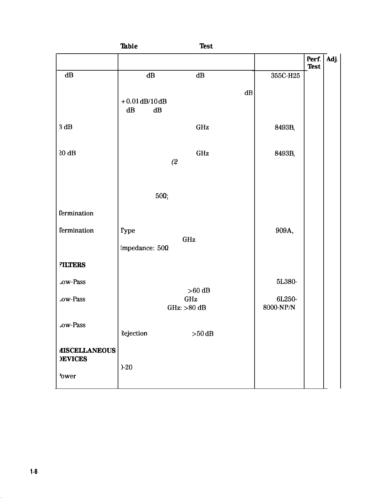
‘Ihble
l-l. Recommended Test Equipment (4 of 6)
Instrument
1 dB Step
Attenuator
3 dB
Attenuator
30 dB
Attenuator
I’ERMINATIONS
krmination
rermination
Fermination
Critical Specifications for
Equipment Substitution
Steps: 1 dB from 0 to 12
dB
Frequency: 20 MHz to 1500 MHz
Calibrated to uncertainty error of f(0.02
+O.Ol dB/lO dB
0 dB to 12
Frequency: 200 Hz to 18
step) at 20 MHz from
dB
GHz
SMA Connectors
Frequency: 200 Hz to 18
SMA Connectors (2
Impedance:
5OQ;
BNC
GHz
required)
Impedance: 500; SMA (m)
I’ype
N Male Connector
Frequency: dc to 18
GHz
[mpedance: 5061
Recommended
Model
HP
355C-H25
dB
HP
Option 003
HP
Option 020
HP 11593A
HP 1810-0118
HP
Option 012
8493B,
8493B,
909A,
Perf,
Test
X
X
X
Adj,
X
X
X
FIIXERS
Jaw-Pass
Jaw-Pass
Jaw-Pass
vlISCELLANEOUS
IEVICES
Filter
Filter
Filter
‘recision
‘ower
Supply
kt-off Frequency: 250 MHz
Rejection at 460 MHz: >60
kt-off Frequency: 8
iejection at 14
GHz
GHz: >80 dB
ht-off Frequency: 1200 MHz
Xejection
I-20
at 1500 MHz:
volts, O-2 amperes
>50 dB
dB
K&L
5L380-
250-B/B
K&L
6L250-
8000-NP/N
HP 360B
HP 6114A
X
X
X
X
l-6
General information
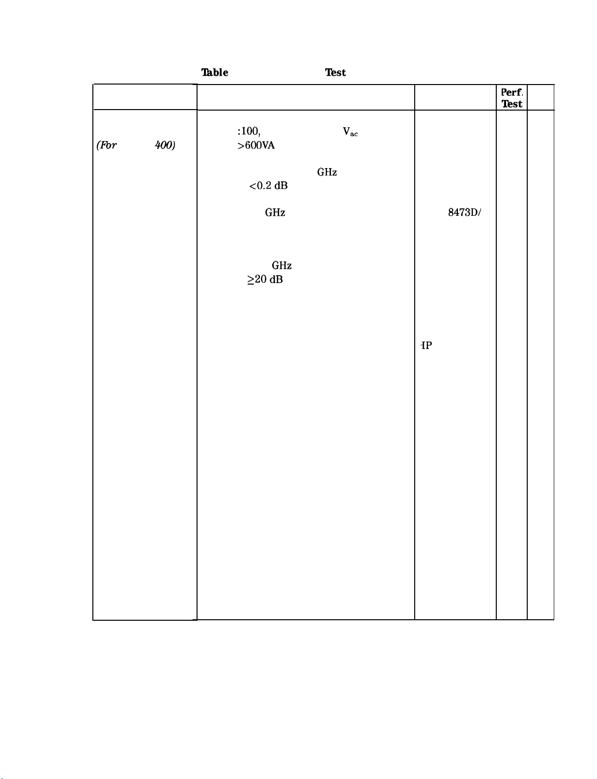
‘able
l-l. Recommended Test Equipment (5 of 6)
Instrument
AC Line-Power
Source
(Rx- Option
400)
Power
Splitter
Planar-doped
Barrier Diode
Detector
Reactive Power
Divider
SPECIAL
DEVICES
Display
Adjustment
PC Board*
Critical Specifications for
Equipment Substitution
Frequency: 400 Hz
Voltage
Power:
Frequency: 1 MHz to 22
Tracking:
10 MHz to 33
Range: 2 to 22
Isolation: 220
:lOO,
120, 220, or 240
>6OOVA
~0.2 dB
GHz
GHz
dB
V,,
GHz
Required for preliminary display adjustment!
Recommended
Model
California Instr-
uments Model
153T Opt. 400
HP 11667B
HP
8473D/
HP 8474C
Omni-Spectra
2090-6202-00
IP
85662-60088
Perf,
Test
X
X
Adj.
X
X
X
Low-Noise
DC Supply
Crystal Filter
Bypass Network
CABLES
Low-Loss Microwave
Cable
Cable
Cable
Test Cable*
(Optional)
Refer to Figure 3-109. (4
Refer to Figure 3-108.
required)
APC 3.5 (m)
BNC, 122 cm (48 in.) (3
required)
SMA (m) to SMA (m)
BNC (m) to SMB Snap-On (f)
HP 8120-4921
10503A
5061-1086
IP 85680-60093
X
X
X
X
X
X
General Information 1-7
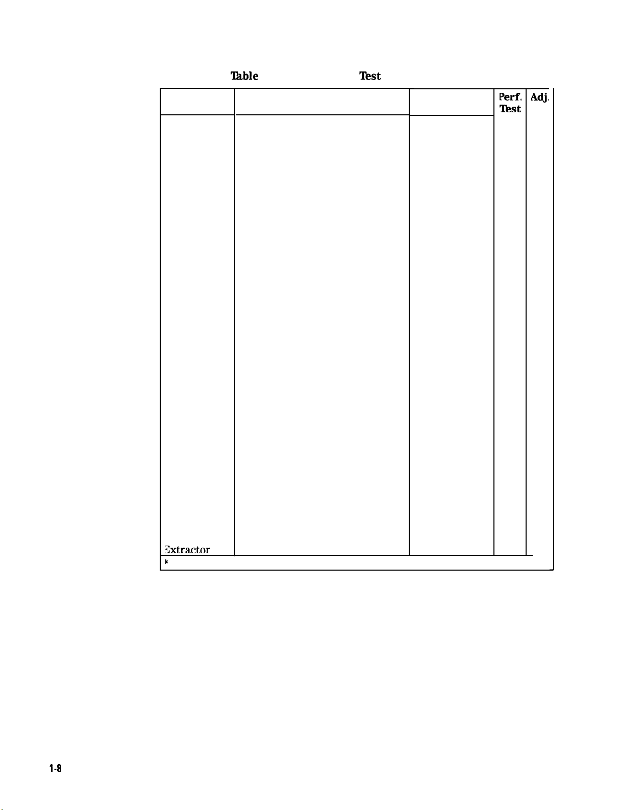
‘Ihble
l-l. Recommended Test Equipment (6 of 6)
Instrument Critical Specifications for
Equipment Substitution
ADAPTERS
Adapter
Adapter
Adapter
Adapter
Adapter
Adapter
Adapter
Adapter
Adapter
Adapter
Adapter
Adapter
Adapter
Adapter
Adapter
Adapter
Adapter
Adapter
Adapter
Adapter
Adapter
Adapter
Type N (f) to BNC (m)
SMB snap on (m) (m)
SMB (m) to SMA (f)
SMB (m) bulkhead
Type N (f) to N (f)
Type N (m) to N (m)
Type N (m) to BNC (f) (2
BNC Tee (m)(f)(f) (2
required,
required)
SMA (f) to SMA (f)
SMA (m) to SMA (m)
BNC (f) to SMA (m)
BNC (f) to SMB (f)
Type N (m) to SMA (f)
BNC to aligator clip
Type N (f) to BNC (m)
APC-3.5 (m) to Type N (m)
Type N (m) to APC-3.5 (f)
APC-3.5 (f) TO N (f) (2
required)
APC-3.5 (f) to APC-3.5 (f)
APC-3.5 (m) to Type N (f)
BNC (f) to dual bannana plug
Type N (f) to SMA (f)
Recommended
Model
1250-0077
1250-0672
1250-0674
1250-0691
1250-1477
1250-0778
1250-0780
1250-0781
1250-l 158
1250-1159
1250-1200
1250-1236
1250-1250
1250-1292
1250-1477
1250-1743
1250-1744
1250-1745
1250-1749
1250-1750
1251-2277
HP 86290-60005
Perf.
Test
X
X
X
X
X
X
X
X
X
Adj,
X
X
X
X
X
X
X
X
X
X
X
X
X
X
BOARD
EXTENDERS
See Figure l-l.
?C Board PC Board extracting tool
Xxtractor
t
Part of Service Accessories
HP 03950-4001
X
l-8
General Information
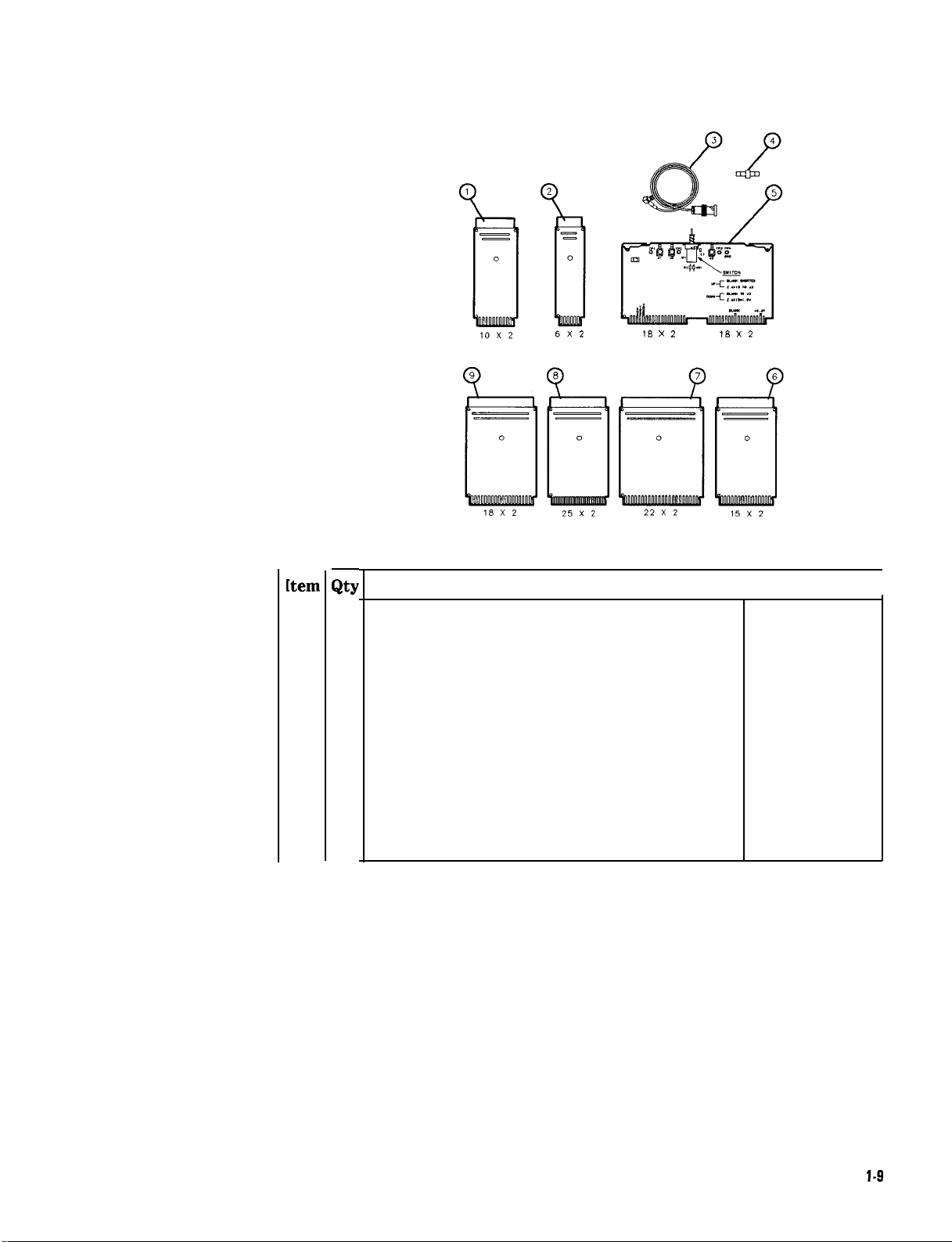
6X2
18 x 2
18 x 2
kern
1
2
3
4
5
6 3
7
8
9
G
1
Extender
2
Extender
2
Cable: 4-foot long; BNC to SMB snap-on
1
Adapter: SMB snap-on male to SMB snap-on male
1
PC Board: Display Adjustment Test
Extender
1
Extender
1
Extender
2
Extender
Figure l-l. Service Accessories, HP Part Number 08566-60001
Board:
Board:12contacts,
Board:30contacts;
Board:44contacts;
Board:50contacts;
Board:36contacts;
Description
20
contacts,
2
rows of
2
rows of
2
rows of
2
rows of
2
rows of
2
rows of
10
6
15
22
25
18
HP Fart Number
I
85680-60028
08505-60109
85680-60093
85662-60088
08505-60041
08505-60107
85680-60034
08505-60042
I
1250-0669
General Information
l-9

Performance Tksts
2
Introduction
Verifkation
Specifications
of
The procedures in this section test the instrument’s electrical
performance using the Specifications in the Installation and
Verification Manual as the performance standards. None of the
tests require access to the interior of the instrument. The manual
Performance Tests provided in this section should be performed only
if semi-automatic test equipment (for Operation Verification) is not
available or the Performance Test is not in the Operation Verification
Program. (Refer to the Installation and Verification Manual for
information on Operation Verification.)
When a complete verification of specifications is required, proceed as
follows:
1. Run the Operation Verification Program.
2. The Operation Verification Program verifies compliance with
specifications of all tests it performs. The tests not performed by
the Operation Verification Program must be done manually and are
as follows:
n
Sweep Time Accuracy (including Fast Sweep Time Accuracy)
n
Noise Sidebands
n
Harmonic and Intermodulation Distortion
n
Image, Multiple, and Out-of-Band Responses
n Frequency Reference Error
n
Center Frequency Readout Accuracy
If the results of a performance test are marginally within
specification, go to the Adjustments section of this manual and
perform the related adjustments procedures. When an adjustment is
directly related to a performance test, the adjustment procedure is
referenced under RELATED ADJUSTMENT in the performance test.
Performance Tests
2-l

‘Ihble
2-1. Performance Test Cross-Reference
Function or Characteristic Tested Test Performance Test
No.
Center Frequency Readout
Frequency Spans
3-dB
Bandwidths*
Bandwidth Shape*
Bandwidth Amplitudes*
Log Scales
IF Gains
Log and Linear Amplifier Fidelityt
CAL OUTPUT Level
Frequency Response
Sweep Times
Noise Sidebands
Line-Related Sidebands
Noise Floor
Residual Responses
Harmonic and Intermodulation Distortion
1
Center Frequency Readout Accuracy Test
2
Frequency Span Accuracy Test
3
Resolution Bandwidth Accuracy Test
4
Resolution Bandwidth Selectivity Test
5
Resolution Bandwidth Switching Uncertainty Test
6
Log Scale Switching Uncertainty Test
7
IF Gain Uncertainty Test
8
Scale Fidelity Test
9
Calibrator Amplitude Accuracy Test
10 Frequency Response Test
11
Sweep Time Accuracy Test
12 Noise Sidebands Test
13 Line-Related Sidebands Test
14
Average Noise Level Test
15 Residual Responses Test
16
Harmonic and Intermodulation Distortion Test
Image, Multiple, and Out-of-Band Responses
Gain Compression
1ST
LO OUTPUT Amplitude
SWEEP+ TUNE OUT
Fast Sweep Times
Frequency Reference
‘For Option 462 instruments, refer to Chapter 4.
tFor
Option 857 instruments, refer to Chapter 5.
Calibration
Cycle
This instrument requires periodic verification of performance. The
instrument should have a complete verification of specifications at
least every six months.
17
Image, Multiple, and Out-of-Band Responses Test
18 Gain Compression Test
19 1ST
20
21
22
LO OUTPUT Amplitude Test
SWEEP + TUNE OUT Amplitude Test
Fast Sweep Time Accuracy Test (~20 ms)
Frequency Reference Error Test
2-2 Performance Tests
Equipment
Required
Equipment required for the manual performance tests and
adjustments is listed in
equipment that satisfies the critical specifications given in the list may
be substituted for the recommended model.
‘Ikble
l-l, Recommended Test Equipment. Any
Performance
Record
Note
Test
The Operation Verification Program provides a detailed test record
when a printer is used with the controller. If manual performance
tests are done, the results of the performance tests may be tabulated
on the HP 8566B Performance Test Record at the end of this chapter.
The HP 8566B Performance Test Record lists all of the tested
specifications and the acceptable ranges for the measurement values
obtained during the tests.
Allow l/2 hour warm up time for the HP 8566B before beginning the
Performance Tests.
Performance Tests 2-3

1. Center
Frequency Readout
Accuracy
‘l&t
Related
Specifications
Adjustments
10 MHz Standard Adjustment
Sweep, DAC, and Main Coil Driver Adjustments
For spans <n X 5 MHz, f (2% of frequency span + frequency
reference error X center frequency + 10 Hz).
For spans >n X 5 MHz, f (2% of frequency span + n X 100
frequency reference error X center frequency).
n* Center Frequency
1
100 Hz to 5.8
2 5.8
GHz
to 12.5
3 12.5
4
>18.6
GHz
GHz
GHz
to 18.6
GHz
GHz
* n is the harmonic mixing number, depending on center
frequency.
kHz +
SPECTRUM ANALYZER
Figure 2-l. Center Frequency Test Setup
FAEOUENCY
STANDARD
24 Performance Tests
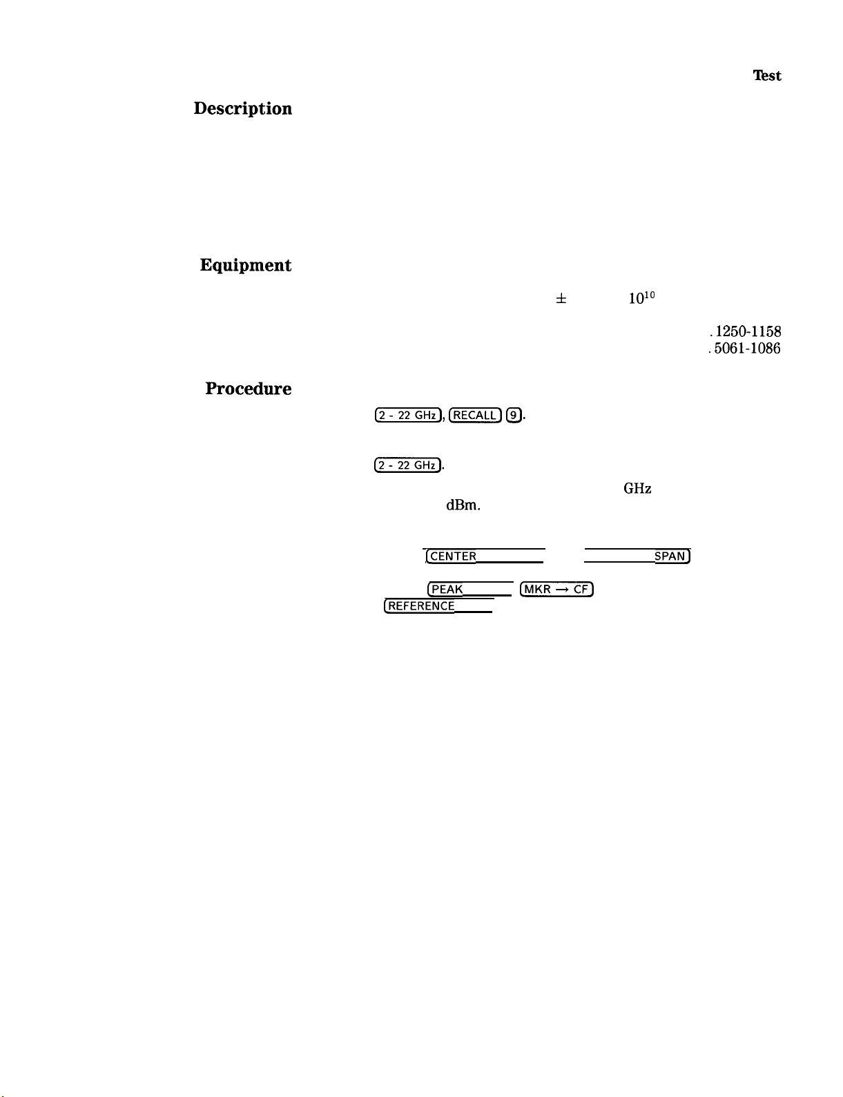
1. Center Frequency Readout Accuracy Test
Description
Equipment
Procedure
A synthesized signal source that is phase-locked to a known frequency
standard is used to input a signal to the analyzer. The frequency
readout of the analyzer is compared to the actual input frequency
for several different frequency settings over the analyzer’s range.
The signal source is phase-locked to a standard known to be as
accurate as the analyzer’s internal frequency reference to minimize
the “frequency reference error X center frequency” term of the
specifications.
Synthesized Sweeper . . . . . . . . . . . . . . . . . . . . . . . . . . . . HP 8340A
Frequency Standard . . . . .
a 10 MHz standard with accuracy within
f
1 part in
lOlo
such as HP 5061A
Adapter, Type N (m) to SMA (f) , . . . . . . . . . . . . . . . . . . . . . 1250-1250
Adapter, SMA (f) to SMA (f) . . . . . . . . . . . . . . . . . . . . . .
.1250-1158
Cable Assembly, SMA Male Connectors . . . . . . . . . . . . . . . . . .5061-1086
1.
Connect CAL OUTPUT to RF INPUT.
2.
Press
c$???KJ IRECALL) @.
3.
Adjust FREQ ZERO for a maximum amplitude trace.
4.
Press
(2-j.
5.
Set the synthesized sweeper for a 2.000000
approximately 0
dBm.
GHz
signal at a level of
6.
Connect equipment as shown in Figure 2-l.
7.
Set analyzer
CCENTER
FREQUENCY) and (FREQUENCY
SPAN)
and
synthesized sweeper frequency according to Table 2-2. At each
setting, press
Adjust
CREFERENCE
CPEAK
SEARCH],
LEVEL) as necessary to place signal peak at a
c-1
to center the signal.
convenient level.
8.
Record the CENTER FREQUENCY readout in the table for each
setting. The limits for this frequency are given in the table. Refer
to Figure 2-2.
Performance Tests 2-5
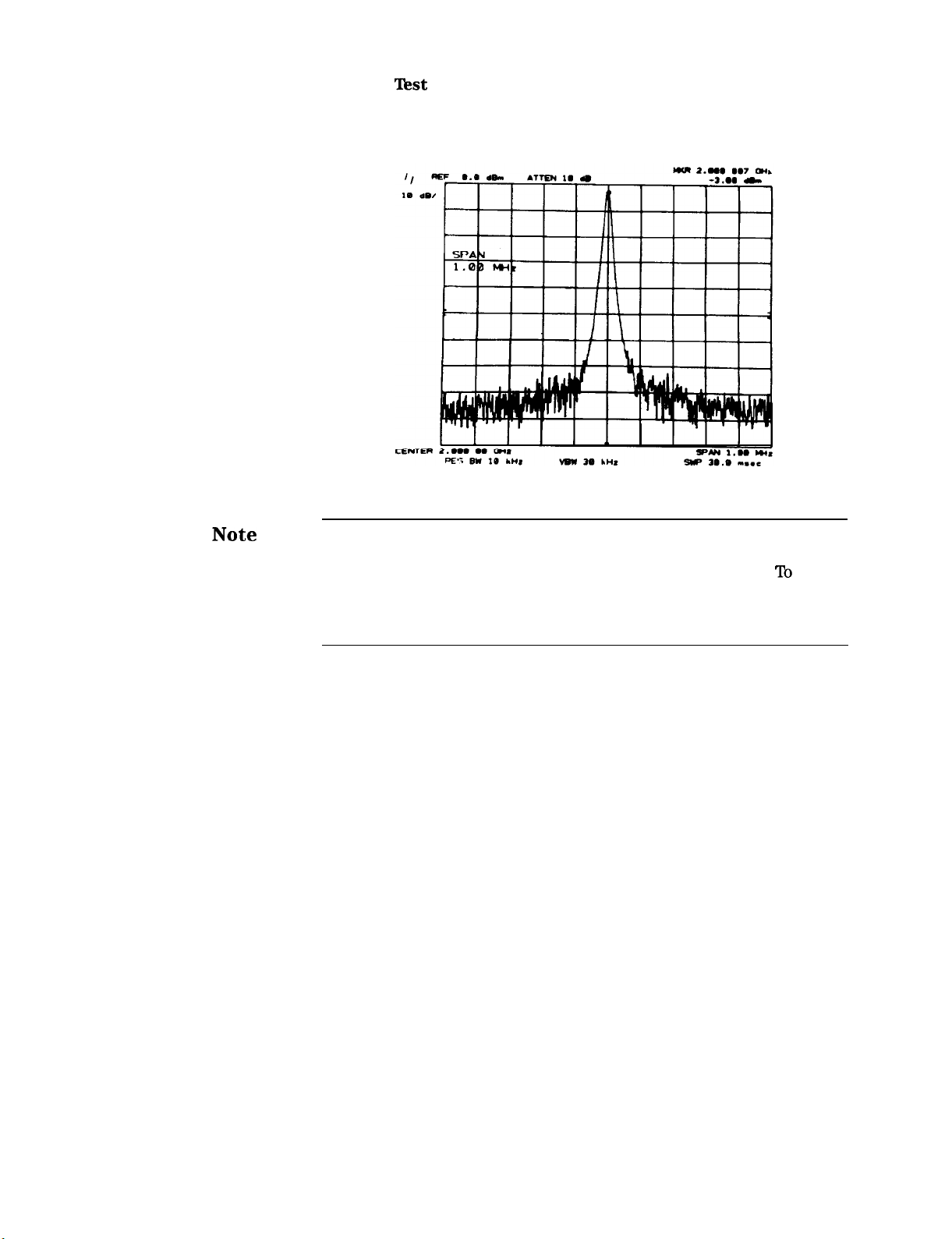
1. Center Frequency Readout Accuracy Test
Figure 2-2. Center Frequency Accuracy Measurement
Note
The spectrum analyzer CENTER FREQUENCY readout may fall
outside of the specified limits if the internal frequency reference
of the analyzer has not been calibrated within the past year.
To
eliminate the “frequency reference error X center frequency” error,
the analyzer’s 10 MHz Frequency Reference Output (on the rear
panel) may be substituted for the frequency standard.
2-6 Performance Tests
 Loading...