


Operating and Service Manual
Agilent Technologies
85133E/F/H
NMD-2.4 mm -f- to 2.4 mm
Flexible
Test Port Return Cables
Agilent Part Number: 85133-90017
Printed in USA
Print Date: February 2008
Edition 5
Supersedes: October 2007
© Copyright 1990, 2006 - 2008 Agilent Technologies, Inc. All rights reserved.

Documentation Warranty
THE MATERIAL CONTAINED IN THIS DOCUMENT IS PROVIDED "AS IS," AND IS
SUBJECT TO BEING CHANGED, WITHOUT NOTICE, IN FUTURE EDITIONS.
FURTHER, TO THE MAXIMUM EXTENT PERMITTED BY APPLICABLE LAW,
AGILENT DISCLAIMS ALL WARRANTIES, EITHER EXPRESS OR IMPLIED WITH
REGARD TO THIS MANUAL AND ANY INFORMATION CONTAINED HEREIN,
INCLUDING BUT NOT LIMITED TO THE IMPLIED WARRANTIES OF
MERCHANTABILITY AND FITNESS FOR A PARTICULAR PURPOSE. AGILENT
SHALL NOT BE LIABLE FOR ERRORS OR FOR INCIDENTAL OR CONSEQUENTIAL
DAMAGES IN CONNECTION WITH THE FURNISHING, USE, OR PERFORMANCE
OF THIS DOCUMENT OR ANY INFORMATION CONTAINED HEREIN. SHOULD
AGILENT AND THE USER HAVE A SEPARA TE WRITTEN AGREEMENT WITH
WARRANTY TERMS COVERING THE MATERIAL IN THIS DOCUMENT THAT
CONFLICT WITH THESE TERMS, THE WARRANTY TERMS IN THE SEPARATE
AGREEMENT WILL CONTROL.
DFARS/Restricted Rights Notice
If software is for use in the performance of a U.S. Government prime contract or
subcontract, Software is delivered and licensed as “Commercial computer software” as
defined in DFAR 252.227-7014 (June 1995), or as a “commercial item” as defined in FAR
2.101(a) or as “Restricted computer software” as defined in FAR 52.227-19 (June 1987) or
any equivalent agency regulation or contract clause. Use, duplication or disclosure of
Software is subject to Agilent Technologies’ standard commercial license terms, and
non-DOD Departments and Agencies of the U.S. Government will receive no greater than
Restricted Rights as defined in FAR 52.227-19(c)(1-2) (June 1987). U.S. Government users
will receive no greater than Limited Rights as defined in FAR 52.227-14 (June 1987) or
DFAR 252.227-7015 (b)(2) (November 1995), as applicable in any technical data.
ii 85133E/F/H

CAUTION
The cable center conductor is fragile and will be seriously damaged if the
cable is stretched, bent too tightly, or bent too oft en. Cables break when the
bend radius is too small—less than 2.5” (6 cm) for 1.85 mm cables, and less
than 4” (10 cm) for 2.4 mm cables.
Use the following guidelines with cables:
• Never coil the cable too tightly.
• Never allow the cable to hang down from an instrument test port, or a
storage fixture, or while holding it.
• Never bend the cable an excessive number of times.
85133E/F/H iii

Printing Copies of Documentation from the Web
To print copies of documentation from the Web, download the PDF file from the Agilent
web site:
•Go to http://www.agilent.com.
• Enter the document’s part number (located on the title page) in the Search box.
• Click Search.
• Click on the hyperlink for the document.
• Click the printer icon located in the tool bar.
iv 85133E/F/H

1. General Information
The Cable Sets . . . . . . . . . . . . . . . . . . . . . . . . . . . . . . . . . . . . . . . . . . . . . . . . . . . . . . . . . . . . . . . . . . . . . .1-2
85133E . . . . . . . . . . . . . . . . . . . . . . . . . . . . . . . . . . . . . . . . . . . . . . . . . . . . . . . . . . . . . . . . . . . . . . . . . .1-2
85133F . . . . . . . . . . . . . . . . . . . . . . . . . . . . . . . . . . . . . . . . . . . . . . . . . . . . . . . . . . . . . . . . . . . . . . . . . .1-2
85133H . . . . . . . . . . . . . . . . . . . . . . . . . . . . . . . . . . . . . . . . . . . . . . . . . . . . . . . . . . . . . . . . . . . . . . . . . . 1-2
Connector Designators . . . . . . . . . . . . . . . . . . . . . . . . . . . . . . . . . . . . . . . . . . . . . . . . . . . . . . . . . . . . . .1-2
Clarifying the Terminology of a Connector Interface . . . . . . . . . . . . . . . . . . . . . . . . . . . . . . . . . . . . . .1-3
Incoming Inspection. . . . . . . . . . . . . . . . . . . . . . . . . . . . . . . . . . . . . . . . . . . . . . . . . . . . . . . . . . . . . . . . . .1-3
Preventive Maintenance . . . . . . . . . . . . . . . . . . . . . . . . . . . . . . . . . . . . . . . . . . . . . . . . . . . . . . . . . . . . . . 1-4
Replaceable Parts. . . . . . . . . . . . . . . . . . . . . . . . . . . . . . . . . . . . . . . . . . . . . . . . . . . . . . . . . . . . . . . . . . . . 1-4
2. Specifications
Environmental Requirements . . . . . . . . . . . . . . . . . . . . . . . . . . . . . . . . . . . . . . . . . . . . . . . . . . . . . . . . . 2-2
Electrical Specifications. . . . . . . . . . . . . . . . . . . . . . . . . . . . . . . . . . . . . . . . . . . . . . . . . . . . . . . . . . . . . . . 2-2
Supplemental Characteristics. . . . . . . . . . . . . . . . . . . . . . . . . . . . . . . . . . . . . . . . . . . . . . . . . . . . . . . . . . 2-3
Center Conductor Pin Depth . . . . . . . . . . . . . . . . . . . . . . . . . . . . . . . . . . . . . . . . . . . . . . . . . . . . . . . . .2-3
3. Use, Maintenance, and Care of the Cables
Electrostatic Discharge . . . . . . . . . . . . . . . . . . . . . . . . . . . . . . . . . . . . . . . . . . . . . . . . . . . . . . . . . . . . . . .3-2
Visual Inspection . . . . . . . . . . . . . . . . . . . . . . . . . . . . . . . . . . . . . . . . . . . . . . . . . . . . . . . . . . . . . . . . . . . .3-3
Look for Obvious Defects and Damage First. . . . . . . . . . . . . . . . . . . . . . . . . . . . . . . . . . . . . . . . . . . . .3-3
Inspect the Mating Plane Surfaces . . . . . . . . . . . . . . . . . . . . . . . . . . . . . . . . . . . . . . . . . . . . . . . . . . . .3-3
Precision Slotless Connectors (2.4 mm) . . . . . . . . . . . . . . . . . . . . . . . . . . . . . . . . . . . . . . . . . . . . . . . . . .3-4
Cleaning Connectors . . . . . . . . . . . . . . . . . . . . . . . . . . . . . . . . . . . . . . . . . . . . . . . . . . . . . . . . . . . . . . . . . 3-5
Gaging Connectors. . . . . . . . . . . . . . . . . . . . . . . . . . . . . . . . . . . . . . . . . . . . . . . . . . . . . . . . . . . . . . . . . . . 3-7
Connector Gage Accuracy. . . . . . . . . . . . . . . . . . . . . . . . . . . . . . . . . . . . . . . . . . . . . . . . . . . . . . . . . . . .3-7
When to Gage Connectors . . . . . . . . . . . . . . . . . . . . . . . . . . . . . . . . . . . . . . . . . . . . . . . . . . . . . . . . . . .3-7
Gaging Procedures . . . . . . . . . . . . . . . . . . . . . . . . . . . . . . . . . . . . . . . . . . . . . . . . . . . . . . . . . . . . . . . . .3-8
Making Connections . . . . . . . . . . . . . . . . . . . . . . . . . . . . . . . . . . . . . . . . . . . . . . . . . . . . . . . . . . . . . . . . 3-10
How to Make a Connection. . . . . . . . . . . . . . . . . . . . . . . . . . . . . . . . . . . . . . . . . . . . . . . . . . . . . . . . . . 3-10
How to Separate a Connection. . . . . . . . . . . . . . . . . . . . . . . . . . . . . . . . . . . . . . . . . . . . . . . . . . . . . . .3-12
Handling and Storage . . . . . . . . . . . . . . . . . . . . . . . . . . . . . . . . . . . . . . . . . . . . . . . . . . . . . . . . . . . . . . . 3-12
Avoiding Cable Movement . . . . . . . . . . . . . . . . . . . . . . . . . . . . . . . . . . . . . . . . . . . . . . . . . . . . . . . . . .3-13
Contents
4. Replaceable Par ts
Ordering Replaceable Parts. . . . . . . . . . . . . . . . . . . . . . . . . . . . . . . . . . . . . . . . . . . . . . . . . . . . . . . . . . . . 4-2
Ordering One Cable in a Cable Set . . . . . . . . . . . . . . . . . . . . . . . . . . . . . . . . . . . . . . . . . . . . . . . . . . . .4-2
Returning a Cable or Cable Set to Agilent . . . . . . . . . . . . . . . . . . . . . . . . . . . . . . . . . . . . . . . . . . . . . . .4-3
Contacting Agilent . . . . . . . . . . . . . . . . . . . . . . . . . . . . . . . . . . . . . . . . . . . . . . . . . . . . . . . . . . . . . . . . . 4-3
Information About Network Analyzers. . . . . . . . . . . . . . . . . . . . . . . . . . . . . . . . . . . . . . . . . . . . . . . . . 4-3
A. Connector Care Quick Reference
Principles of Microwave Connector Care . . . . . . . . . . . . . . . . . . . . . . . . . . . . . . . . . . . . . . . . . . . . . . . . .A-2
85133E/F/H
1

Contents
2
85133E/F/H

1 General Information
85133E/F/H 1-1
General Information
The Cable Sets
The Cable Sets
The Agilent 85133E/F/H flexible cable sets are designed for use with Agilent network
analyzers that have male NMD-2.4 mm test ports.
85133E
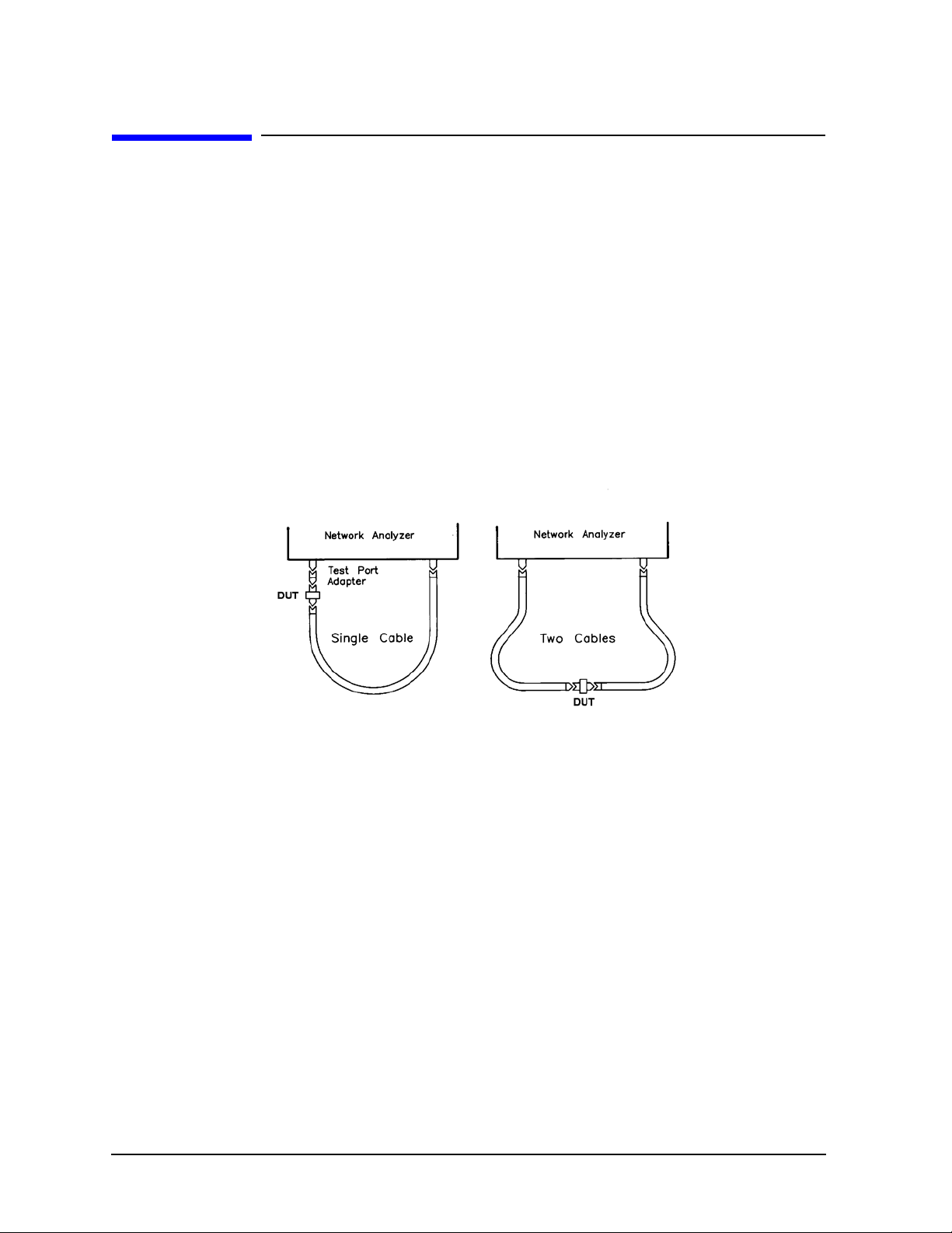
The 85133E set contains a single cable. Use it when a DUT is connected, with the
appropriate adapter, directly to the test set test port. See Figure 1-1.
85133F
The 85133F set contains two cables. Each is shorter than the 85133E cabl e. Use the
85133F cables when a DUT is connected between cable ends. See Figure 1-1.
Figure 1-1 Cable Configurations
85133H
The 85133H set contains a single cable – the -f- to -m- cable from the 85133F cable set. It is
shorter than the 85133E single cable. See Figure 1-1.
Connector Designators
NMD Connectors
NMD denotes a connector that has larger than standard coupling threads for greater
stability. NMD connectors are used on test cables, test ports, test port adapters, and test
port cables.
Female slotted NMD test port connectors are used on the test set end of adapters and
cables, and cannot be connected to standard male connectors.
Male NMD connectors are used on tes t sets (as test p orts), and on the DUT end of adapters
and cables. Male connectors have both the larger threads (for use with test port adapters)
and standard threads (for direct coupling to a DUT).
1-2 85133E/F/H

General Information
Incoming Inspection
PSC Connectors
PSC denotes a precision slotless connector. Precision slotless connectors are metrology
grade connectors that have better electrical performance, better repeatability, and are
more durable than slotted connectors.
Clarifying the Terminology of a Connector Interface
In this document and in the prompts of the PNA calibration wizard, the gender of cable
connectors and adapters is referred to in terms of the center conductor. For example, a
connector or device designated as 1.85 mm –f– has a 1.85 mm female center conductor.
8510-series , 872 x , a nd 87 5x ON LY: In contrast, during a measurement calibration, the
network analyzer softkey menus label a 1.85 mm calibration device with reference to the
sex of the analyzer’s test port connector—not the calibration device connector. For
example, the label SHORT(F) refers to the short that is to be connected to the fem a le test
port. This will be a male short from the calibration kit.
Table 1-1 Clarifying the Sex of Connectors: Examples
Terminology Meaning
Short
–f–
Short (f) Male short (male center conductor) to be connected to female port
A connector gage is referred to in terms of the connector that it measures. For instance, a
male connector gage has a female connector on the gage so that it can measure male
devices.
Female short (female center conductor)
Incoming Inspection
Verify that the shipment is complete by referring to Table 4-1 on page 4-4.
If the case or any device appears damaged, or i f the shipment is incompl ete, not ify Agilent.
See “Contacting Agilent” on page 4-3. Agilent will arrange for repair or replacement of
incomplete or damaged shipments without waiting for a settlement from the
transportation company.
When you send the cable set to Agilent, include the following information:
• your company name and address
• the name of a technical contact person within your company, and the person’s complete
phone number
• the model number and serial number of the cable set
85133E/F/H 1-3

General Information
Preventive Maintenance
• the part number and serial number of the device
• the type of ser v i ce re q u i red
•a detailed description of the problem
Preventive Maintenance
The best techniques for maintaining the integrity of the cables include:
• routine visual inspection
• cleaning
• proper gaging
• proper connection techniques
• proper storage
All of the above are described in Chapter 3. Failure to detect and remove dirt or metallic
particles on a mating plane surface can degrade repeatability and accuracy and can
damage any connector mated to it. Improper connections, resulting from center conductor
values being out of limits (see Table 2 on page 2-4), or from bad connections, can also
damage cable connectors.
Replaceable Parts
See Table 4-1 on page 4-4 for a complete list of cable set contents and their associated part
numbers (you can order a single cable rather than the entire cable set), and for
recommended items not included with the cable set. Refer to “Contacting Agilent” on
page 4-3 for information about communicating with Agilent.
1-4 85133E/F/H

2 Specifications
85133E/F/H 2-1

Specifications
Environmental Requirements
Environmental Requirements
Table 2-1 Environmental Requirements
Parameter Limits
Operating temperature +20 °C to +26 °C (+68 °F to +79 °F)
Storage temperature −40 °C to +75 °C (−40 °F to +167 °F)
Altitude
Operation < 4,500 meters (≈15,000 feet)
Storage < 4,500 mete rs (≈15,000 feet)
Relative humidity Always non-condensing
Operation Up to 80% at 30°C
Storage Up to 95% at 40°C
Electrical Specifications
Table 2-2 Electrical Specifications
Cable SWR Return Loss
(dB)
85133E ≤1.44 ≥15 ≤0.1 + 0.57√f
85133F ≤0.1 + 0.38√f
85133H
a. f = frequency in GHz.
Insertion
Loss (dB)
+ 0.02f
+ 0.017f
Frequency Range
a
(GHz)
DC to 50
2-2 85133E/F/H
Specifications
Supplemental Characteristics
Supplemental Characteristics
T able 2-3 lists supp lementa l perfor mance char acte ristic s. These are not specifi cati ons, but
are intended to provide additional information useful to your application. Supplemental
characteristics are typical (but not warranted) performance parameters.
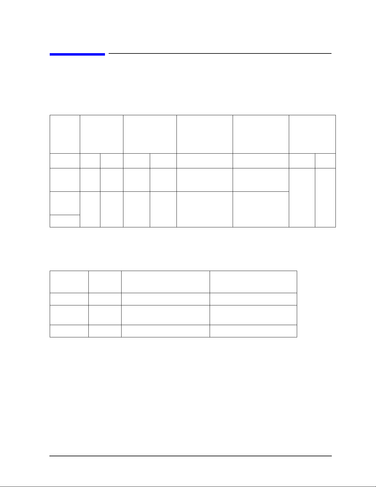
Table 2-3 Supplemental Characteristics (1 of 3)
Cable Cable Length Approximate
Electrical Length
cm in m ft cm in
85133E 97.2 38.25 1.125 3.690 <0.15 dB Change
85133F 62.9 24.75 0.7376 2.418 <0.08 dB Change
85133H
a. (f) = frequency in GHz.
b. With a 90°, 2.5-inch bend radius.
c. After three 90°, 2.5-inch bend radius/straighten cycles.
Magnitude and
Phase Stability
With a 90°
a,b
Bend
<0.17° (f) + 0.5°
<0.08° (f) + 0.5°
Random Use
Magnitude and
Phase Stability
<0.07 dB Change
<0.09° (f) + 0.5°
<0.04 dB Change
<0.04° (f) + 0.5°
Table 2-3 Supplemental Characteristics (2 of 3)
Cable Set N umber
of Cables
85133E 1 NMD-2.4 mm -f- Slotted PSC-2.4 mm -f- Slotless
Test Set End Connector Typ e DUT End Connector Type
Minimum
Recommended
a,c
Bend Radius
6.352 2.5
85133F 2 NMD-2.4 mm -f- Slotted NMD-2.4 mm -m- and
PSC-2.4 mm -f- Slotless
85133H 1 NMD-2.4 mm -f- Slotted NMD-2.4 mm -m-
Center Conductor Pin Depth
Center conductor pin depth is the distance the center conductor mating plane differs from
being flush with the outer conductor mating plane. See Figure 2-1 The pin depth of a
center conductor can be in one of two states: either protruding or recessed.
Protrusion is the condition in which the center conductor extends beyond the outer
conductor mating plane. This c ondition will indi cate a pos itive value on the c onnector gage.
Recession is the condition in which the center conductor is set back from the outer
conductor mating plane. This condition will indi cate a negative value on the connector
gage.
85133E/F/H 2-3
 Loading...