


User's Guide
HP 8510 Pulsed-RF Network Analyzer
ABCDE
08510{90505
No.
Part
HP
Printed
in
USA
March
1995

Notice
The information contained in this do cument is sub ject to change without notice.
Hewlett-Packard makes no warrantyofany kind with regard to this material, including,
but not limited to, the implied warranties of merchantability and tness for a particular
purpose. Hewlett-Packard shall not b e liable for errors contained herein or for incidental or
consequential damages in connection with the furnishing, performance, or use of this material.
Restricted Rights Legend.
Use, duplication, or disclosure by the U.S. Government is sub ject to restrictions as set forth
in subparagraph (c) (1) (ii) of the Rights in Technical Data and Computer Software clause
at DFARS 252.227-7013 for DOD agencies, and subparagraphs (c) (1) and (c) (2) of the
Commercial Computer Software Restricted Rights clause at FAR 52.227-19 for other agencies.
c
Cop
yrigh
t
adaptation, or
cop
ta
the
Rosa
Systems
under
San
Hewlett-P
1988
translation
la
t
yrigh
Division,
ws.
ard
ack
without
1400
Compan
prior
oun
F
.
y
written
taingro
Righ
All
ermission
p
Pkwy,
e
v
ts
San
Reserv
prohibited,
is
ta
ed.
Rosa,
Repro
CA
duction,
except
as
95403-1799
allo
ed
w
CERTIFICATION
Hewlett-Packard Company certies that this product met its publishedspecications at the
time of shipment from the factory. Hewlett-Packard further certies that its calibration
measurements aretraceable to the United States National Institue of Standards and Technology
(NIST, formerly NBS), to the extent al lowed by the institute's calibration facility, and to the
calibration facilities of other International Standards Organization members.
WARRANTY
This Hewlett-Packard instrument product is warranted against defects in material and
workmanship for a perio d of one year from date of delivery. During the warranty period,
Hewlett-Packard Company will, at its option, either repair or replace pro ducts whichproveto
be defective.
For warranty service or repair, this product must be returned to a service facility designated
byHP.Buyer shall prepay shipping charges to HP and HP shall payshippingcharges to
return the pro duct to Buyer. However, Buyer shall pay all shipping charges, duties, and taxes
for products returned to HP from another country.
HP warrants that its software and rmware designated by HP for use with an instrument
will
es
do
unin
execute
arrant
not w
terrupted
programming
its
that the
error
or
operation
free.
instructions
the
of
LIMIT
prop
when
instrumen
ATIONS
erly
t,
OF
or
W
installed
are,
w
soft
ARRANTY
on that
rm
or
instrument.
will
are
w
HP
e
b
y
eration
op
b
or
foregoing
The
Buy
er,
Buy
the
outside
main
NO
of
tenance.
OTHER
DISCLAIMS
AR
P
A
OR
F
arrant
w
er-supplied
vironmen
en
ARRANTY
W
IMPLIED W
THE
TICULAR
not
shall
y
are
w
soft
sp
tal
IS
PURPOSE.
defects
to
apply
terfacing,
in
or
ecications
EXPRESSED
for
OR
ARRANTIES OR
CLUSIVE
EX
resulting
unauthorized
duct,
pro
the
IMPLIED.
CHANT
MER
REMEDIES
improp
from
dication
mo
improp
or
SPECIFICALLY
HP
ABILITY
er
or
er site
tenance
main
misuse,
preparation
FITNESS
AND
THE REMEDIES PROVIDED HEREIN ARE BUYER'S SOLE AND EXCLUSIVE
REMEDIES. HP SHALL NOT BE LIABLE FOR ANY DIRECT, INDIRECT, SPECIAL,
INCIDENTAL, OR CONSEQUENTIAL DAMAGES, WHETHER BASED ON CONTRACT,
TORT, OR ANY OTHER LEGAL THEORY.
ANCE
customer
e
assistanc
e agr
d Sales and Servic
ements
available
e
ar
eOc
e. A
for
ddresses
maintenanc
duct
o
Pr
Hewlett-Packar
dPr
For any assistanc
eprovided at the b
ar
ements
e
agr
e
oducts.
ontact your ne
e, c
ack of this manual.
ASSIST
other
and
arest Hewlett-Packar
iii

Contents
1. Introduction
Organization of This Do cument. . . . . . . . . . . . . . . . . . . . . 1-1
System Description . . . . . . . . . . . . . . . . . . . . . . . . . 1-1
Principles of Pulsed-RF Network Measurements . . . . . . . . . . . . . 1-1
Pulse Measurements Overview . . . . . . . . . . . . . . . . . . . . 1-1
Operating the HP 8510 for Pulsed-RF Measurements . . . . . . . . . . 1-1
Frequency Domain Point-in-Pulse Measurements . . . . . . . . . . . . 1-2
Pulse Prole Domain Measurements . . . . . . . . . . . . . . . . . . 1-2
General Timing Information . . . . . . . . . . . . . . . . . . . . . 1-2
Using External Triggering and Pulse Mo dulation . . . . . . . . . . . . 1-2
High P
Reference
er Measuremen
ow
Data
.
. .
. .
.
.
.
.
.
.
.
.
.
.
.
.
.
.
.
.
.
ts .
.
.
.
. .
. .
. .
. .
.
.
.
.
.
.
.
.
.
.
.
.
.
.
.
1-2
1-2
System
2.
Who
Principles
3.
Pulse
Pulse
Dut
Pulse
Rise/F
Trigger Delay. . . . . . . . . . . . . . . . . . . . . . . . . . . . . 3-2
Pulse Prole Measurement Resolution Perio d . . . . . . . . . . . . . . . 3-3
4. Pulse Measurements Overview
Pulsed-RF S-parameters versus Frequency . . . . . . . . . . . . . . . . 4-1
Pulse
Op
5.
System Connections
Turn On System P
Operator's Chec
Description
.
.
.
.
.
.
.
.
.
.
.
.
.
ts?
.
.
.
.
.
.
.
.
. .
.
.
.
.
.
.
.
.
.
.
.
.
.
.
.
.
.
.
.
.
.
.
.
.
.
ts
.
.
.
.
.
.
.
.
.
.
.
.
.
.
.
.
.
.
. .
. .
.
.
.
.
.
.
.
.
.
.
.
.
.
.
.
.
.
.
.
.
.
.
.
.
.
.
.
. .
. .
.
.
.
.
.
.
.
.
.
.
.
.
.
.
.
.
.
. .
. .
. .
. .
.
.
.
.
.
.
.
.
.
.
.
.
.
.
.
.
.
. .
.
.
.
.
.
.
.
.
.
.
Measuremen
. . . . . . . . . . . . . . . . . . 5-3
t State Files
. . . . . . . . . . . . . . . . . 5-5
.
.
.
.
ts
. . . . . . . . . 5-3
.
.
.
.
.
.
.
.
.
.
.
. .
.
.
.
.
.
w
Net
PRP
PRF
,
.
.
. .
.
.
.
.
Pulsed-RF
for
k
Measuremen
.
.
.
. .
.
.
Measuremen
ork
.
.
.
.
.
.
. .
.
.
.
. .
.
.
.
.
.
Pulsed-RF
e
of
Set
etition
etition
Mak
eration
Op
w
Signal
of
the
T
Flo
Pulsed-RF
eriod,
P
requency
F
.
.
.
.
.
.
. .
.
.
.
.
. .
. .
Domain
HP
Hardware State and Instrumen
k . . . . . . . . . .
riggering
.
8510
. . . . . . . . . . . . . . . . . . . . . . . . .
ower . . . . . .
Chec
Should
Theory
est
T
Rep
Rep
Cycle
y
Width
all Time
Prole
erating
Load Pulse
Pulse Prole Domain Check . . . . . . . . . . . . . . . . . . . . . 5-5
Frequency Domain Check . . . . . . . . . . . . . . . . . . . . . . 5-7
External
.
.
.
.
.
.
.
. 3-2
.
. 5-1
.
2-1
2-2
2-3
3-1
3-1
3-2
3-2
4-3
5-9
Contents-1
6. Frequency Domain Point-in-Pulse Measurements
Measurement Calibration for Point-in-Pulse . . . . . . . . . . . . . . . 6-1
Measurement. . . . . . . . . . . . . . . . . . . . . . . . . . . . . 6-1
Set Pulse Polarity . . . . . . . . . . . . . . . . . . . . . . . . . . 6-1
Set Pulse Width . . . . . . . . . . . . . . . . . . . . . . . . . . 6-2
Set Duty Cycle Limit . . . . . . . . . . . . . . . . . . . . . . . . 6-2
Set Trigger Delay. . . . . . . . . . . . . . . . . . . . . . . . . . 6-2
Connect the Device Under Test . . . . . . . . . . . . . . . . . . . . 6-2
7. Pulse Prole Domain Measurements
Measurement Calibration for Pulse Prole . . . . . . . . . . . . . . . . 7-1
Pulse Prole Domain . . . . . . . . . . . . . . . . . . . . . . . . 7-1
Frequency Domain Using Frequency List . . . . . . . . . . . . . . . . 7-2
Measurement. . . . . . . . . . . . . . . . . . . . . . . . . . . . . 7-4
Set Pulse Polarity . . . . . . . . . . . . . . . . . . . . . . . . . . 7-4
Set Pulse Width . . . . . . . . . . . . . . . . . . . . . . . . . . 7-5
Set Duty Cycle Limit . . . . . . . . . . . . . . . . . . . . . . . . 7-5
Set Measurement Time Span . . . . . . . . . . . . . . . . . . . . . 7-5
.
.
.
. .
. .
. .
.
.
.
.
.
.
.
.
d
erio
Set
Connect
Switc
Measuremen
Device
the
hing Bet
ween
Resolution
t
under
Frequency
P
.
.
est
T
Domain and
. .
. .
Pulse
. .
Prole
. .
.
.
.
Domain
.
.
.
.
.
.
.
.
.
.
.
.
.
.
7-5
7-5
7-7
Information
Cycle
Measuremen
Time
Cycle
t
.
Time
Width
Cycle
y
Prole
Characteristics
el
external
P
a30dBAmplier .
ort 1 and P
User Parameters and Set A
Memories
Normalized
Appropriate
.
. .
.
Limit
Domain
Domain
and
d
erio
P
and Stop
signal
Measuremen
er
w
o
ort 2 A
ttenuators . . . . . . . .
P
and
t
.
.
.
.
.
.
.
.
.
.
.
.
.
.
.
.
.
Time
Stop
rigger
T
Sweep
conditioning .
.
arameters
Measuremen
Measurement
Dela
y Cycle
Dut
Signals
.
.
.
ts
. . . . . . . . . . . . . . . . . . . .
ttenuators .
.
.
.
.
.
.
.
.
.
.
.
.
.
.
.
.
.
.
.
.
.
.
.
.
.
.
.
. .
.
.
.
.
.
.
.
.
.
.
.
.
.
.
.
.
.
.
.
.
.
.
.
.
.
.
. .
.
.
.
.
.
.
.
.
.
.
.
.
.
.
.
.
.
.
.
.
.
.
. .
.
.
.
.
.
.
.
.
.
.
.
.
.
.
.
. .
. .
.
.
.
.
.
.
.
.
.
.
.
.
.
. .
. .
.
.
.
.
.
.
.
.
y
.
.
.
.
.
.
.
Considerations .
.
.
.
.
.
.
.
.
.
. .
.
.
.
.
.
.
.
.
.
.
.
.
.
. .
.
. . . .
els .
. . . . . . . . . . . . .
. . . . . . . . . . . . . 10-5
ttenuators . . . . . . . . . . . . . 10-5
.
.
.
.
.
.
.
.
.
.
.
.
.
.
.
.
Calibration
t
Sequence
.
.
.
.
.
.
.
.
.
.
.
.
.
.
. .
.
.
.
.
.
.
.
.
.
.
. .
.
.
.
.
.
.
.
.
. .
.
.
.
.
.
.
. . . . . . . . . 10-4
. . . 10-5
.
.
. .
.
.
.
.
.
.
.
.
.
.
.
. .
.
.
.
.
.
.
.
.
. .
.
.
.
.
.
.
.
.
.
.
.
.
.
ork
w
Rep
Sw
Pulse
Dut
Pulse
requency
F
Lev
the P
the
Timing
Analyzer
eep
etition
Trigger
High
race
T
the
Calibration
General
8.
Net
Measuremen
Pulse
External
9. Using External Triggering and Pulse Mo dulation
Connect the Pulse Generator . . . . . . . . . . . . . . . . . . . . . . 9-1
10. High Power Measurements
Signal
Connecting
Example
Measure
Measure an Amplier with High Input Lev
Using
Controlling the A
Measure
Changing Signal Path After Calibration . . . . . . . . . . . . . . . . . 10-6
Set the Attenuators . . . . . . . . . . . . . . . . . . . . . . . . . 10-6
Store
View
Selecting
General
. 8-1
.
.
.
.
.
.
.
. 8-5
.
.
.
. 10-3
.
.
.
.
8-3
8-3
8-3
8-3
8-3
8-3
8-4
10-1
10-2
10-3
10-6
10-7
10-7
10-9
Contents-2

General Calibration and Measurement Sequence Using Display Math . . . . 10-9
11. Reference Data
Creating Pulse Hardware State and Instrument State Files . . . . . . . . . 11-1
Pulse Menus . . . . . . . . . . . . . . . . . . . . . . . . . . . . . 11-2
Pulse Conguration Menu . . . . . . . . . . . . . . . . . . . . . . 11-2
DETECTOR: WIDE BW . . . . . . . . . . . . . . . . . . . . . 11-2
DETECTOR: NORMAL BW . . . . . . . . . . . . . . . . . . . 11-3
PULSE WIDTH . . . . . . . . . . . . . . . . . . . . . . . . . 11-3
DUTY CYCLE . . . . . . . . . . . . . . . . . . . . . . . . . . 11-3
PULSE OUT: HIGH . . . . . . . . . . . . . . . . . . . . . . . 11-3
PULSE OUT: LOW. . . . . . . . . . . . . . . . . . . . . . . . 11-3
TRIGGER DELAY . . . . . . . . . . . . . . . . . . . . . . . . 11-3
TRIG MODE: INTERNAL . . . . . . . . . . . . . . . . . . . . 11-3
TRIG MODE: EXTERNAL . . . . . . . . . . . . . . . . . . . . 11-3
HP 8510 Option 008 Added Programming Codes . . . . . . . . . . . . . 11-4
HP 8510 Option 008 Added Query Commands . . . . . . . . . . . . . . 11-4
Contents-3
Figures
1-1. HP 8510 Pulsed-RF Network Analyzer System . . . . . . . . . . . . . 1-3
2-1. Simplied Pulsed-RF Network Analyzer Block Diagram . . . . . . . . . 2-2
2-2. HP 85110A S-Parameter Test Set Signal Flow . . . . . . . . . . . . . 2-4
3-1. Pulse Terms and Denitions . . . . . . . . . . . . . . . . . . . . . 3-3
4-1. Pulsed-RF S-Parameters versus Frequency (Frequency Domain Point-in-Pulse) 4-2
4-2. Pulsed-RF S-Parameters versus Time (Pulse Prole Domain) Measurement
Internal Pulse Output and Internal MeasurementTrigger . . . . . . . 4-4
5-1. System Cable Connections . . . . . . . . . . . . . . . . . . . . . . 5-2
5-2. Typical Response After Recall, Inst. State 8, Frequency, Detector: WB, Mult.
Srce. On . . . . . . . . . . . . . . . . . . . . . . . . . . . . 5-4
.
.
.
.
.
.
.
.
.
.
.
.
. .
. .
. .
. .
er
Prole,
Domain,
5-3.
Pulse Prole,
5-4.
Pulse
5-5.
S
5-6.
11
S
5-7.
11
Amplier
6-1.
Frequency
7-1.
Pulse
7-2.
S
7-3.
21
Minim
7-4.
7-5. S11, Smith
Net
8-1.
Example
8-2.
8-3. External
9-1. External Control of PRP and Duty Cycle . . . . . . . . . . . . . . . 9-2
9-2. Using External Trigger and External Modulation PRP = 10 microseconds,
10-1. Test Set Maximum Signal Levels . . . . . . . . . . . . . . . . . . . 10-2
10-2. Measuring a 30 dB gain Amplier . . . . . . . . . . . . . . . . . . . 10-3
Measuring
10-3.
Option
11-1.
Pulse
User1 a1,
Prole,
requency
F
,
requency
F
,
Prole,
Pulse
,
um
ork
w
Duty Cycle = 50% . . . . . . . . . . . . . . . . . . . . . . . . 9-3
008
S
11
Domain,
Domain,
Gain,
Displa
List
requency
F
Prole,
Time
Chart
Analyzer
ternal
In
Trigger
Amplier
an
Domain,
F
Span,
Mark
Marker
.
.
.
.
Pulse
Pulse
requency
During
y
List
Thru
.
Measuremen
Pulse
and Stop
.
Resolution P
.
.
.
Output
with
ulus,
Stim
.
.
.
Width
Width
Domain
Measuremen
Segmen
.
.
.
.
.
.
Cycle
t
PRP
Sweep
High
and
.
.
.
.
.
.
10
10
t-in-Pulse .
oin
P
Num
t
.
.
.
d
erio
.
.
.
.
and Dut
Timing
Input Lev
System
.
.
.
.
.
.
rigger
s,T
rigger
s,T
Calibration
t
er
b
. .
.
100
=
.
.
.
.
.
.
y Cycle
Diagram
els
Men
1
ns
us
. .
.
.
.
.
.
.
.
.
.
.
.
.
.
.
. .
. .
.
.
.
.
.
.
.
.
.
.
.
s .
5
y
Dela
.
.
.
.
. .
s
15
y
Dela
.
.
.
.
.
.
.
.
.
.
.
.
.
.
.
.
.
.
.
.
.
.
.
. .
.
.
.
.
.
.
.
.
.
.
.
.
.
.
.
.
.
.
.
.
.
.
.
.
.
.
.
.
.
.
.
.
.
.
. .
. .
.
.
.
.
.
.
.
.
.
.
.
.
. .
. .
.
.
.
.
.
.
.
.
.
.
. .
. .
.
.
.
.
.
.
.
.
.
.
.
.
. .
.
.
.
.
.
.
.
.
.
.
.
.
.
.
.
.
.
.
. .
.
.
5-4
5-6
5-6
5-7
5-8
6-3
7-3
7-3
7-4
7-6
7-6
8-2
8-4
8-5
10-4
11-5
Contents-4
1
Introduction
This documentisintended for use with the HP 8510B/C Option 008 Network Analyzer
and is a supplement to the HP 8510B/C Operating and Programming manual. It contains
descriptions of the pulsed-RF network analyzer system features for measurements in the
frequency domain and in the pulse prole domain. With respect to the standard, swept CW
system, op eration of the pulsed-RF system is identical except that the measurement is made
at a specic, known time during each pulse. For information ab out network analysis, please
refer to HP Pro duct Note 8510-10, HP 8510B Introductory User's Guide, for an introduction
to using the front panel for measurement setup, measurement calibration, and basic network
measurements.
Organization
section
This
ts
ten
con
System
duces
tro
In
Principles
of
list
A
con
h
eac
of
Description
HP 8510B/C
the
Pulsed-RF
of
terms
the
of
tains
hapter.
c
and
This
a
Document
hapters
c
the
of
list
Option
Netw
008
ork
denitions used
cumen
do
this
in
Pulsed-RF
measuremen
Measurements
in pulsed-RF
netw
description
brief
a
and
t
capabilit
t
ork measuremen
y
ts.
the
of
.
Pulse Measurements Overview
A description of how the network analyzer measures pulsed-RF S-parameters versus frequency
and versus time.
Operating
Describes the setup, measuremen
the
t calibration, and measuremen
Pulsed-RF
for
8510
HP
system and making pulsed-RF measuremen
Measurements
t pro cess for setting up the
ts.
Introduction
1-1
Frequency Domain Point-in-Pulse Measurements
This chapter contains measurement calibration and measurement procedures to display the
pulsed-RF S-parameters versus frequency.
Pulse Profile Domain Measurements
This chapter contains measurement calibration and measurement procedures to display the
pulsed-RF S-parameters versus time.
General Timing Information
Descriptions of the internal timing to show the system's internal pulse repetition period and
duty cycle capabilities.
Using External Triggering and Pulse Modulation
This section contains information to help you determine if your application requires external
tain
t.
accuracy
mo
pulse
P
High
Discusses
making
when
dulating
er
w
o
the
equipmen
t,
Measurements
considerations
ecial
sp
at
measuremen
ts
instructions
and
high
required
o
p
RF
wer
for
protect
to
lev
connecting
the
els.
the
test
external
system
equipmen
main
and
Reference
option
all
ws
Sho
Data
008
men
structures
u
and
denitions,
ey
k
including
programming
co
des.
1-2
Introduction

Figure
1-1.
HP
8510
Pulsed-RF
Netw
ork
Analyzer
System
Introduction
1-3

System Description
This chapter contains the following information.
A description of the HP 8510 Pulsed-RF Network Analyzer System.
A simplied blo ck diagram of the HP 8510 Pulsed-RF Network Analyzer System.
A signal ow diagram of the HP 85110-series S-parameter Test Set.
Who Should Make Pulsed-RF Measurements?
Pulsed-RF stim
the
y
destro
could
tested
e
b
ust
m
8510 pulsed-RF
HP
The
optimized
pulsed-RF
circuits
a
at
to
in
devices
rm
resp
vides
pro
precisely
ma
o
tw
whic
kno
jor
h
ulus ma
device,
using
are
w
onses.
precise
wn,
areas:
accept
y
PRF
a
netw
feature
or
F
sync
eatable
rep
tests
CW
a
required
e
b
as
h
suc
and
ork
to
set
rst
the
hronization
whic
in
input
in
when
duty
analyzer
e
mak
time,
during
time
the
h
and
where
cases
testing
cycle that
conguration
error-corrected
fully
com
the
the
with
the pulse.
ulus
stim
duce
pro
con
ccurs
o
accurately
bination
pulse, allo
signal
pulsed
a
tin
prior
adds
This
to
output.
application
uous
pack
to
represen
ecialized
sp
S-parameter
wideband
of
wing
extends
device
the
aging, or
ts
S-parameters
of
where the
nal
its
hardw
measuremen
and
IF
HP
the
pulsed,
is
8510
2
signal
test
the
device
application.
an
and
are
of
ts
accurate timing
measured
e
b
to
applications
of
tests
and
same
the
high p
mo
in
ow
Calibration
de.
pulsed-RF
er,
data
is
8510
HP
The
vironmen
en
measuremen
pulsed-RF
our
y
as
t
ou
y
t,
net
measuremen
calibrate
can
w
ork
analyzer
or
F
t.
in the
system
example,
same high
allo
if
po
ws
ou are
y
wer,
calibrate
to
ou
y
making a
pulsed-RF
taken only while the pulse is on. This type of calibration mayprevent damage to calibration
standards that would be damaged in high p ower, CW calibrations.
The recommended conguration of the HP 85108 Pulsed-RF Network Analyzer consists of the
following items.
HP
rm
8510B/C
revision
are
w
net
work
B.05.11
analyzer
greater
or
equipp
ed
(for
Option
with
HP 8510B),
the
008,
or
Wideband
revision
IF,
C.06.54
or
greater
(for
8510
HP
and
HP 8510C).
HP 83622 syn
HP 83624
synthesized sweeper with options 003, 004, and 008.
thesized sw
eeper with options 001, 003, 004, and
HP 85110-series pulsed-RF fundamen
tally mixed S-parameter test set
008.
Also, other external equipmentsuchaspower ampliers, bias supplies and pulse generators
system.
ma
e
b
y
included in
the
System
Description
2-1
The pulsed-RF network analyzer system allows you to select either the normal precision 10
kHz IF bandwidth or the new wideband 3 MHz IF bandwidth. The wide IF and detection
bandwidth allows testing using pulses as short as 1 microsecond but with accuracy comparable
to traditional non-pulsed measurements.
These system components may b e rack-mounted or arranged on a desktop.
Theory of Operation
A simplied blo ck diagram of the system is shown in Figure 2-1. One synthesizer provides
the test signal stimulus to the RF input of the test set and the other provides the LO signal
to the four frequency converters (only two are shown). The LO source is always tuned 20
MHz ab ove the test signal source. The standard internal phaselo cktechnique is not used;
instead, a common 10 MHz frequency reference is used for both of these sources and the
internal sample selection and timing logic in the HP 8510. These sources are considered to b e
coherent, thus generating the correct 20 MHz rst IF and the correct clock frequency for the
reference and test synchronous detectors. This eliminates the need to use the reference signal
for receiver phaselock and allows all reference and test signals to be pulsed, therebymaking
fully error-corrected 2-port, pulsed-RF S-parameter measurements p ossible.
Figure 2-1. Simplified Pulsed-RF Network Analyzer Block Diagram
detectors
exible
y the HP 8510
and
in
accurate
Using
erate
op
wider
a
at
bandwidth
MHz,
20
of device resp onse during the
oth the
b
reference
measuremen
and
sample
t
timing
circuits
sync
IF,
test
the
pulse. With the sources and test set con
hronous
allow
trolled b
over the 8510 system bus, and with all necessary pulse generation and measuremen
signals generated in
ternally from a common
pulsed-RF stimulus/resp onse test system. One pulse of a
each data poin
t and the measuremen
t is sync
10 MHz reference, the HP 85108 is a complete
user-specied width is measured at
hronized so that it is made at a certain kno
that
analysis
t timing
wn
time in the pulse. The stimulus duty cycle can be predicted for a given instrument state,
but the actual pulse repetition perio d depends upon the current domain, cal type, averaging,
y
dut
to
eep
sw
cycle,
2-2
time,
refer
System
pulse
and
to General
Description
width
Timing
selections.
Information.
this reason,
or
F
sensitiv
device
our
y
if
is
e
Either the internal logic, the TTL Trigger Input, or the HP-IB Group Execute Trigger from
an external controller can initiate a measurement cycle. When control of the pulse repetition
period and duty cycle is required, the HP 8510 can use the trigger input to synchronize with
the internal or an external pulse mo dulator. The HP 8510 Stop Sweep output can b e used as
a gating signal to tell when the analyzer is ready for the next measurement. The measurement
is made with 100 nanosecond resolution and ab out 200 picosecond uncertainty with respect to
the internally- or externally-generated measurement trigger.
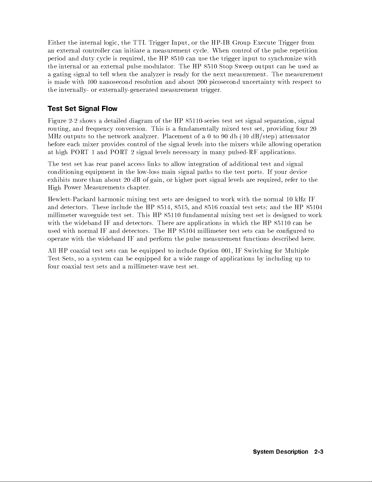
Test Set Signal Flow
Figure 2-2 shows a detailed diagram of the HP 85110-series test set signal separation, signal
routing, and frequency conversion. This is a fundamentally mixed test set, providing four 20
MHz outputs to the network analyzer. Placement of a 0 to 90 db (10 dB/step) attenuator
before each mixer provides control of the signal levels into the mixers while allowing operation
at high PORT 1 and PORT 2 signal levels necessary in many pulsed-RF applications.
The test set has rear panel access links to allow integration of additional test and signal
conditioning equipment in the low-loss main signal paths to the test ports. If your device
exhibits more than about 20 dB of gain, or higher port signal levels are required, refer to the
chapter.
include
test
IF
and
ts
mixing
set.
detectors.
and
detectors.
the HP
IF
This
and
sets
test
8514, 8515,
85110
HP
There
HP
The
erform
p
designed to
are
and
fundamen
applications
are
85104
pulse
the
work
coaxial
8516
mixing
tal
millimeter
measuremen
with the
whic
in
test sets
sets;
test
test
the
h
can
functions
t
normal 10
and
is
set
HP
e
b
describ
HP
the
designed
can
85110
congured
ed
kHz
to
IF
85104
w
e
b
to
here.
ork
w
o
P
High
Hewlett-P
detectors.
and
millimeter
the
with
with
used
with
erate
op
Measuremen
er
ard
k
ac
These
eguide
v
a
w
wideband
normal
the wideband
harmonic
IF
All
Test
four
coaxial
HP
Sets,
coaxial
so
a
test
sets
test
system
sets
can
and
can b
a
equipp
e
e
b
equipp
ed
millimeter-w
ed
for
a
v
to
a
e
include
wide
set.
test
Option
range
001,
applications
of
IF
Switc
hing
including
y
b
for
Multiple
to
up
System
Description
2-3
Figure
2-2.
HP
85110A
arameter
S-P
T
est
Signal Flo
Set
w
2-4
System
Description
3
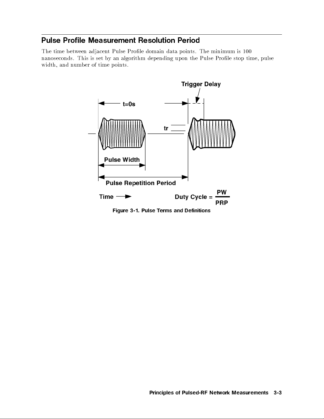
Principles of Pulsed-RF Network Measurements
This chapter contains a list of terms used to describ e the pulsed-RF stimulus and resp onse.
Figure 3-1 shows a typical envelope of the pulsed-RF waveform output by the RF signal
source. For internal measurement triggering, the RF frequency and the ON time of the pulse
is controlled by the HP 8510 so that there is one pulse per measurement.
Pulse Repetition Period, PRP
The time from the 50 percentpoint on the rising edge of one pulse to the 50 percentpointon
pulse.
next
the
of
edge
rising
the
eration
ternal
in
or
F
ypically
T
and
time
for
width
the
is
The
the
frequency
ab
pulse.
up
pulse
In
PRP
making the
millisecond
calibration
PRP
the
If
triggering
is
there
measuremen
the
time
measuremen
next
and
30
out
maxim
during
e,
yp
t
con
is
op
pulse
one
tis
next
the
til
un
cycle
y
dut
domain,
when
milliseconds. In
PRP
um
of
part
width,
pulse
trolled
externally
the analyzer with the pulse.
Pulse
Repetition
Frequency,
the
measuremen
er
p
made at
pulse
and
t
limit.
the
out
ab
measuremen
the
dut
system
some
consists
second,
analyzer
Pulse
the
milliseconds.
3
y cycle,
HP
the
,
PRF
PRF
PRP
The
t.
user-sp
rst
necessary
if
tuned
is
Prole
Other
t.
and pulse
external trigger
8510
=
PRP
up
ends
dep
time
aiting
w
the
a
time
eraging,
v
turned ON
next
the
whic
pulse is
ecied
the
of
,
to
domain,
With
factors
prole domain
1
the
on
relativ
required
satisfy
to
frequency,
frequency
the
aect
h
stop time.
input is
instrumen
user-sp
a
for
the
to
e
the
for
user-sp
the
the
es
do
can
PRP
system
the
used to
t state.
ecied
of
start
analyzer
ecied
maxim
hange,
c
not
ab
e
b
PRP
sync
the
set
to
um
1
out
are
hronize
Principles
Pulsed-RF
of
Netw
Measurements
ork
3-1
Duty Cycle
The ratio of the time that the pulse is ON to the total Pulse Repetition Period. If the pulse
ON and OFF times are equal, the Duty Cycle is 50 p ercent.
For internal op eration, the maximum duty cycle percent limit can b e specied, but the actual
duty cycle may b e less, depending upon the user-specifed pulse width and the time it takes for
the analyzer to set up for the next measurement.
Pulse Width
The ON time from the 50 percent p oint on the rising edge to the 50 percentpointonthe
falling edge.
The internally-generated Pulse Width can b e set from less than 100 nanoseconds to 40.88
milliseconds.
Time
Rise/F
all
time
es
for
time:
the
pulse
to
rise
from
the
10
The
tr
The
=
pulse
pulse
time
transition
rise
tak
it
condition.
time
fall
pulse
=
tf
90
the
from
fall
to
pulse
the
for
es
tak
it
time
The
condition.
The
normal
IF
resp
onds
rise/fall
to
times
out 75
ab
of
to rise/fall times of about 300 nanoseconds.
y
Trigger
time
The
In the F
Dela
the
that
ON
pulse
after
requency domain, the T
measuremen
rigger Dela
t
y can be set from do
(internal) or +3 resolution p eriods (external) and
Prole domain the trigger dela
width,
and number of p oin
y is automatic depending upon the displa
ts.
ON
t
ercen
p
ON
t
ercen
p
microseconds; the
actually made.
is
condition
condition to
to
the 10
wideband IF
90 p
the
wn to -6 resolution perio
up to 40.88 milliseconds. In the Pulse
y time span, pulse
ercen
ercen
p
ON
t
ON
t
responds
ds
3-2
Principles
Pulsed-RF
of
Netw
Measurements
ork
Pulse Profile Measurement Resolution Period
The time b etween adjacent Pulse Prole domain data p oints. The minimum is 100
nanoseconds. This is set by an algorithm depending upon the Pulse Prole stop time, pulse
width, and number of time points.
Figure
3-1.
Pulse
erms
T
Definitions
and
Principles
Pulsed-RF
of
Netw
Measurements
ork
3-3

4
Pulse Measurements Overview
This chapter contains information about how the HP 8510 pulsed-RF network analyzer system
measures pulsed-RF S-parameters versus frequency and versus time.
The pulsed-RF conguration allows use of vector network analysis techniques for twotypes of
measurements:
Pulsed-RF S-Parameters versus Frequency
. The measurementissynchronized with the
pulse so that the measurement result is the S-parameter at a sp ecic user-specied pointin
the pulse at each frequency of the sweep
Pulse Prole
. The system is tuned to a single frequency and the measurementis
synchronized with the pulse so that the measurement result is the S-parameter as a function
of time
during the
Pulsed-RF
with
the
p
of
oin
tests
pulse.
t
t-in-pulse"
t
the
Pulsed-RF
cess
pro
during
measuremen
domain
measuremen
onse
resp
external
or
F
the
is
trigger. F
trigger
pulse.
S-parameters
frequency domain
the
in
the
that
so
pulse
frequency
h
eac
t
A
certain
a
after
made
measuremen
ternal
or in
pulsed
the
mo
to
de,
eac
h
device
ersus
v
measuremen
the
,
dela
using
t
trigger
stim
oin
p
data
Frequency
accomplished
are
is
t
Figure
in
the
de,
at
the trace
are
ternal pulse
eac
the
sources
.
y
mo
ulus
tof
made
tuned,
4-1
data
h
same
sync
y
b
single,
a
at
the
an
ws
sho
output and
oin
p
terv
in
represents
hronizing
user-sp
is turned
RF
example
the
of
t
after
al
the resp
of this
the
trace
the
onse
measuremen
the
ecied
then
on,
\frequency
ternal
in
represen
pulse is
of
time
the
the
ts
turned on.
device
the
the pulsed stimulus after the falling edge of the externally-generated measurementtrigger.
t
to
Measurements
Pulse
Ov
erview
4-1

Figure 4-1. Pulsed-RF S-Parameters versus Frequency (Frequency Domain Point-in-Pulse)
erview
4-2
Pulse
Measurements
Ov
 Loading...