


Reference Guide
Agilent Technologies
85097B VNA Interface Kit
for Electronic Calibration
Manufacturing Part Number: 85091-90010
Printed in USA
Print Date: March 2003
Supersedes: October 2001
© Copyright 2001, 2003 Agilent Technologies, Inc. All rights reserved.

Documentation Warranty
THE MATERIAL CONTAINED IN THIS DOCUMENT IS PROVIDED "AS IS," AND IS SUBJECT
TO BEING CHANGED, WITHOUT NOTICE, IN FUTURE EDITIONS. FURTHER, TO THE
MAXIMUM EXTENT PERMITTED BY APPLICABLE LAW, AGILENT DISCLAIMS ALL
WARRANTIES, EITHER EXPRESS OR IMPLIED WITH REGARD TO THIS MANUAL AND ANY
INFORMATION CONTAINED HEREIN, INCLUDING BUT NOT LIMITED TO THE IMPLIED
WARRANTIES OF MERCHANTABILITY AND FITNESS FOR A PARTICULAR PURPOSE.
AGILENT SHALL NOT BE LIABLE FOR ERRORS OR FOR INCIDENTAL OR
CONSEQUENTIAL DAMAGES IN CONNECTION WITH THE FURNISHING, USE, OR
PERFORMANCE OF THIS DOCUMENT OR ANY INFORMATION CONTAINED HEREIN.
SHOULD AGILENT AND THE USER HAVE A SEPARATE WRITTEN AGREEMENT WITH
WARRANTY TERMS COVERING THE MATERIAL IN THIS DOCUMENT THAT CONFLICT
WITH THESE TERMS, THE WARRANTY TERMS IN THE SEPARATE AGREEMENT WILL
CONTROL.
Assistance
Product maintenance agreements and other customer assistance agreements are available
for Agilent products.
For any assistance, contact the nearest Agilent Technologies sales or service office. Refer to
Table 2-1 on page 2-4 for a list of Agilent offices.
ii

Contents
1. General Information
VNA Interface Kit Overview . . . . . . . . . . . . . . . . . . . . . . . . . . . . . . . . . . . . . . . . . . . . . . . . . . .1-2
Option 100 . . . . . . . . . . . . . . . . . . . . . . . . . . . . . . . . . . . . . . . . . . . . . . . . . . . . . . . . . . . . . . . .1-2
Compatible Network Analyzers . . . . . . . . . . . . . . . . . . . . . . . . . . . . . . . . . . . . . . . . . . . . . .1-2
VNA Interface Kit Contents . . . . . . . . . . . . . . . . . . . . . . . . . . . . . . . . . . . . . . . . . . . . . . . . . . .1-3
Description of the VNA Interface Kit Contents. . . . . . . . . . . . . . . . . . . . . . . . . . . . . . . . . . .1-4
VNA Interface Kit Setup and Operation. . . . . . . . . . . . . . . . . . . . . . . . . . . . . . . . . . . . . . . . . .1-6
Setup Procedure . . . . . . . . . . . . . . . . . . . . . . . . . . . . . . . . . . . . . . . . . . . . . . . . . . . . . . . . . . .1-6
VNA Interface Kit Characteristics . . . . . . . . . . . . . . . . . . . . . . . . . . . . . . . . . . . . . . . . . . . . . .1-8
Environmental Requirements . . . . . . . . . . . . . . . . . . . . . . . . . . . . . . . . . . . . . . . . . . . . . . . .1-8
Electrical and Mechanical Characteristics . . . . . . . . . . . . . . . . . . . . . . . . . . . . . . . . . . . . . .1-9
Electrostatic Discharge . . . . . . . . . . . . . . . . . . . . . . . . . . . . . . . . . . . . . . . . . . . . . . . . . . . . . .1-10
2. Troubleshooting
General Information. . . . . . . . . . . . . . . . . . . . . . . . . . . . . . . . . . . . . . . . . . . . . . . . . . . . . . . . . .2-2
Returning a VNA Interface Kit to Agilent. . . . . . . . . . . . . . . . . . . . . . . . . . . . . . . . . . . . . . .2-2
Contacting Agilent . . . . . . . . . . . . . . . . . . . . . . . . . . . . . . . . . . . . . . . . . . . . . . . . . . . . . . . . . . .2-4
3. Safety and Regulatory Information
Safety Information . . . . . . . . . . . . . . . . . . . . . . . . . . . . . . . . . . . . . . . . . . . . . . . . . . . . . . . . . . .3-2
Before Applying Power . . . . . . . . . . . . . . . . . . . . . . . . . . . . . . . . . . . . . . . . . . . . . . . . . . . . . .3-2
Instrument Markings . . . . . . . . . . . . . . . . . . . . . . . . . . . . . . . . . . . . . . . . . . . . . . . . . . . . . . .3-3
Safety Earth Ground . . . . . . . . . . . . . . . . . . . . . . . . . . . . . . . . . . . . . . . . . . . . . . . . . . . . . . .3-3
Regulatory Information . . . . . . . . . . . . . . . . . . . . . . . . . . . . . . . . . . . . . . . . . . . . . . . . . . . . . . .3-4
Compliance Notices . . . . . . . . . . . . . . . . . . . . . . . . . . . . . . . . . . . . . . . . . . . . . . . . . . . . . . . .3-4
Contents-i

Contents
Contents-ii

1 General Information
1-1

General Information
VNA Interface Kit Overview
VNA Interface Kit Overview
This manual provides reference information for the Agilent 85097B vector network
analyzer (VNA) interface kit for electronic calibration (ECal).
The VNA interface kit is part of the VNA-based ECal system. The interface kit provides
the hardware to connect and allow data transfer between ECal modules and compatible
network analyzers. See Table 1-1 below.
ECal modules are precision, single-connection devices that provide consistent calibrations
for your network analyzer. ECal uses fully traceable and verifiable electronic standards.
The interface kit does not include the ECal modules, but they can be ordered separately.
For ordering information, see “Contacting Agilent” on page 2-4.
NOTE
For more information about ECal modules, refer to the Electronic Calibration
Module Reference Guide (included with the VNA interface kit).
Option 100
Adds an adapter cable that allows the interface kit to connect to N469x (microwave) ECal
modules. The Option 100 adapter cable can also be ordered separately.
Compatible Network Analyzers
Refer to Table 1-1 for network analyzers and ECal modules compatible with the 85097B
VNA interface kit. The network analyzer must have the appropriate firmware revision
installed to operate with the ECal models shown.
Table 1-1 Supported Network Analyzers and ECal Models
Network Analyzer ECal Model Firmware Revision
8753ES/ET
8719D/ES/ET
8720D/ES/ET
8722D/ES/ET
8509xB/C
8506x
N4431A
N469x
7.68 or higher
a
7.74 or higher
a. Ports A and B only
NOTE
PNA network analyzers are not compatible with the 85097B VNA interface
kit. PNA analyzers allow direct connection of the ECal modules through a
USB connector interface. Refer to the PNA analyzer on-line help system for
more details.
1-2 Chapter 1
General Information
VNA Interface Kit Contents
VNA Interface Kit Contents
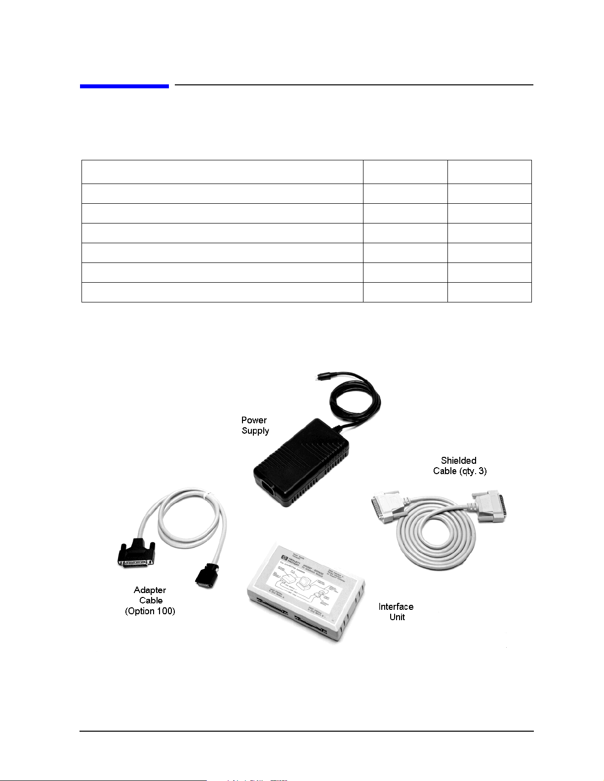
The following table and illustration identify the contents of the 85097B VNA interface kit.
Table 1-2 Contents of the VNA Interface Kit
Description Quantity Part Number
Interface Unit 1 85097-60002
Shielded Cable, DB25 to DB25 3 8120-8710
Adapter Cable, DB25 to AMP Champ (Option 100) 1 8120-1047
Power Supply 1 0950-3331
VNA Interface Kit Reference Guide (this manual) 1 85091-90010
Electronic Calibration Module Reference Guide 1 N4693-90001
Figure 1-1 85097B Kit Contents
Chapter 1 1-3

General Information
VNA Interface Kit Contents
Description of the VNA Interface Kit Contents
This section describes the contents of the 85097B VNA interface kit. Refer to Figure 1-3 on
page 1-7 for a system setup diagram using the kit contents.
NOTE
ECal modules are not included in the 85097B VNA interface kit, but are
ordered separately. Refer to the Electronic Calibration Module Reference
Guide (part number N4693-90001) for information on the types and
specifications of ECal modules.
Interface Unit
The interface unit (shown in Figure 1-1) functions as the digital interface and power source
for ECal modules. The interface can connect to one or two ECal modules. Power is
automatically turned off when an ECal module is disconnected.
NOTE
If you are using an 8506xA microwave module with a serial number below
800, a jumper must be installed in the module to make it compatible with the
interface unit. Contact Agilent for information about returning your module
for this modification. Contact information can be found in Table 2-1 on
page 2-4.
Shielded Cables, DB25 to DB25
The shielded cables (shown in Figure 1-1) are male to male RS-232 cables. Three shielded
cables are included in the kit. The cables connect between the VNA and the interface unit
and between the interface unit and one or two ECal modules (except N469x series). The
length of each shielded cable is 1.8 m.
Adapter Cable, DB25 to AMP Champ (Option 100)
The adapter cable (shown in Figure 1-1) is configured with a DB25 to AMP Champ (36-pin)
connector. The adapter cable connects N469x (microwave) ECal modules to the interface
unit. The adapter cable (part no. 8121-1047) can be ordered separately or by adding
Option 100 to the interface kit. The length of the adapter cable is 1.0 m.
CAUTION
Use only the interface cables supplied with this kit. Other cables may cause
the system to fail EMC specifications.
1-4 Chapter 1
 Loading...