


User’s and Service Guide
Agilent Technologies 85057B
2.4 mm Verification Kit
This manual applies to 85057B verification kits with serial number prefix
3105A.
Agilent Part Number: 85057-90015
Printed in USA
Print Date: November 2005
Supersedes: Ja nuary 2002
© Copyright 1995, 2002, 2005 Agilent Technologies, Inc. All rights reserved.

Documentation Warranty
THE MATERIAL CONTAINED IN THIS DOCUMENT IS PROVIDED "AS IS," AND IS
SUBJECT TO BEING CHANGED, WITHOUT NOTICE, IN FUTURE EDITIONS.
FURTHER, TO THE MAXIMUM EXTENT PERMITTED BY APPLICABLE LAW,
AGILENT DISCLAIMS ALL WARRANTIES, EITHER EXPRESS OR IMPLIED WITH
REGARD TO THIS MANUAL AND ANY INFORMATION CONTAINED HEREIN,
INCLUDING BUT NOT LIMITED TO THE IMPLIED WARRANTIES OF
MERCHANTABILITY AND FITNESS FOR A PARTICULAR PURPOSE. AGILENT
SHALL NOT BE LIABLE FOR ERRORS OR FOR INCIDENTAL OR CONSEQUENTIAL
DAMAGES IN CONNECTION WITH THE FURNISHING, USE, OR PERFORMANCE
OF THIS DOCUMENT OR ANY INFORMATION CONTAINED HEREIN. SHOULD
AGILENT AND THE USER HAVE A SEPARATE WRITTEN AGREEMENT WITH
WARRANTY TERMS COVERING THE MATERIAL IN THIS DOCUMENT THAT
CONFLICT WITH THESE TERMS, THE WARRANTY TERMS IN THE SEPARATE
AGREEMENT WILL CONTROL.
DFARS/Restricted Rights Notice
If software is for use in the per formance of a U.S. Go vernment prime contract or
subcontract, Software is delivered and licensed as “Commercial computer software” as
defined in DFAR 252.227-7014 (June 1995), or as a “commercial item” as defined in FAR
2.101(a) or as “Restricted computer sof tware” as defined in FAR 52.227-19 (June 1987) or
any equivalent agency regulation or contract clause. Use, duplication or disclosure of
Software is subject to Agilent Technologies’ standar d commercial license terms, and
non-DOD Departments and Agencies of the U.S. Government will receive no greater than
Restricted Rights as defined in FAR 52.227-19(c)(1-2) (J une 1987). U.S. Government users
will receive no greater than Limited Rights as defined in FAR 52.227-14 (June 1987) or
DFAR 252.227-7015 (b)(2) (November 1995), as applicable in any technical data.
Assistance
Product maintenance agreements and other customer assistanc e agreements are availa ble
for Agilent products.
For any assistance, contact Agilent Technologies. Refer to page 5-5 for a list of Agilent contacts.
ii 85057B

Printing Copies of This Document
To print copies of this document, download the PDF file from the Agilent Web site:
• Go to http://www.agilent.com.
• Enter the document’s part number (located on the title page) in the Quick Search box.
• Click GO.
85057B iii

iv 85057B

Contents
1. General Information
Verification Kit Overview . . . . . . . . . . . . . . . . . . . . . . . . . . . . . . . . . . . . . . . . . . . . . . . . . . . . .1-2
Kit Contents . . . . . . . . . . . . . . . . . . . . . . . . . . . . . . . . . . . . . . . . . . . . . . . . . . . . . . . . . . . . . .1-2
Compatible Network Analyzers . . . . . . . . . . . . . . . . . . . . . . . . . . . . . . . . . . . . . . . . . . . . . . .1-2
Equipment Required but Not Supplied . . . . . . . . . . . . . . . . . . . . . . . . . . . . . . . . . . . . . . . . .1-3
Incoming Inspection. . . . . . . . . . . . . . . . . . . . . . . . . . . . . . . . . . . . . . . . . . . . . . . . . . . . . . . . . .1-3
Recording the Device Serial Numbers . . . . . . . . . . . . . . . . . . . . . . . . . . . . . . . . . . . . . . . . . . .1-3
Clarifying the Terminology of a Connector. . . . . . . . . . . . . . . . . . . . . . . . . . . . . . . . . . . . . . . .1-4
Preventive Maintenance . . . . . . . . . . . . . . . . . . . . . . . . . . . . . . . . . . . . . . . . . . . . . . . . . . . . . .1-4
2. Specifications
Environmental Requirements . . . . . . . . . . . . . . . . . . . . . . . . . . . . . . . . . . . . . . . . . . . . . . . . . .2-2
Temperature—What To Watch Out For. . . . . . . . . . . . . . . . . . . . . . . . . . . . . . . . . . . . . . . . .2-2
Mechanical Characteristics . . . . . . . . . . . . . . . . . . . . . . . . . . . . . . . . . . . . . . . . . . . . . . . . . . . .2-3
Pin Depth. . . . . . . . . . . . . . . . . . . . . . . . . . . . . . . . . . . . . . . . . . . . . . . . . . . . . . . . . . . . . . . . .2-3
Supplemental Characteristics . . . . . . . . . . . . . . . . . . . . . . . . . . . . . . . . . . . . . . . . . . . . . . . .2-4
Airline Characteristics . . . . . . . . . . . . . . . . . . . . . . . . . . . . . . . . . . . . . . . . . . . . . . . . . . . . . .2-5
Electrical Specifications. . . . . . . . . . . . . . . . . . . . . . . . . . . . . . . . . . . . . . . . . . . . . . . . . . . . . . .2-7
3. Use, Maintenance, and Care of the Devices
Electrostatic Discharge . . . . . . . . . . . . . . . . . . . . . . . . . . . . . . . . . . . . . . . . . . . . . . . . . . . . . . .3-2
Visual Inspection . . . . . . . . . . . . . . . . . . . . . . . . . . . . . . . . . . . . . . . . . . . . . . . . . . . . . . . . . . . .3-3
Look for Obvious Defects and Damage First. . . . . . . . . . . . . . . . . . . . . . . . . . . . . . . . . . . . .3-3
What Causes Connector Wear?. . . . . . . . . . . . . . . . . . . . . . . . . . . . . . . . . . . . . . . . . . . . . .3-3
Inspect the Mating Plane Surfaces . . . . . . . . . . . . . . . . . . . . . . . . . . . . . . . . . . . . . . . . . . . .3-3
Inspect Female Connectors. . . . . . . . . . . . . . . . . . . . . . . . . . . . . . . . . . . . . . . . . . . . . . . . . . .3-4
Cleaning Connectors . . . . . . . . . . . . . . . . . . . . . . . . . . . . . . . . . . . . . . . . . . . . . . . . . . . . . . . . .3-5
Gaging Connectors . . . . . . . . . . . . . . . . . . . . . . . . . . . . . . . . . . . . . . . . . . . . . . . . . . . . . . . . . . .3-7
Connector Gage Accuracy. . . . . . . . . . . . . . . . . . . . . . . . . . . . . . . . . . . . . . . . . . . . . . . . . . . .3-7
When to Gage Connectors. . . . . . . . . . . . . . . . . . . . . . . . . . . . . . . . . . . . . . . . . . . . . . . . . . . .3-7
Gaging Procedures . . . . . . . . . . . . . . . . . . . . . . . . . . . . . . . . . . . . . . . . . . . . . . . . . . . . . . . . . 3-8
Gaging 2.4 mm Connectors. . . . . . . . . . . . . . . . . . . . . . . . . . . . . . . . . . . . . . . . . . . . . . . . .3-8
Gaging the Airline. . . . . . . . . . . . . . . . . . . . . . . . . . . . . . . . . . . . . . . . . . . . . . . . . . . . . . .3-10
Connections. . . . . . . . . . . . . . . . . . . . . . . . . . . . . . . . . . . . . . . . . . . . . . . . . . . . . . . . . . . . . . . .3-14
How to Make a Connection. . . . . . . . . . . . . . . . . . . . . . . . . . . . . . . . . . . . . . . . . . . . . . . . . .3-14
Preliminary Connection . . . . . . . . . . . . . . . . . . . . . . . . . . . . . . . . . . . . . . . . . . . . . . . . . .3-14
Final Connection Using a Torque Wrench. . . . . . . . . . . . . . . . . . . . . . . . . . . . . . . . . . . .3-14
Connecting the Airline . . . . . . . . . . . . . . . . . . . . . . . . . . . . . . . . . . . . . . . . . . . . . . . . . . .3-16
How to Separate a Connection. . . . . . . . . . . . . . . . . . . . . . . . . . . . . . . . . . . . . . . . . . . . . . .3-18
Handling and Storage . . . . . . . . . . . . . . . . . . . . . . . . . . . . . . . . . . . . . . . . . . . . . . . . . . . . . . .3-18
4. Performance Verification
Introduction . . . . . . . . . . . . . . . . . . . . . . . . . . . . . . . . . . . . . . . . . . . . . . . . . . . . . . . . . . . . . . . .4-2
How Agilent Verifies the Devices in Your Kit. . . . . . . . . . . . . . . . . . . . . . . . . . . . . . . . . . . . . .4-2
Recertification. . . . . . . . . . . . . . . . . . . . . . . . . . . . . . . . . . . . . . . . . . . . . . . . . . . . . . . . . . . . . . .4-3
How Often to Recertify . . . . . . . . . . . . . . . . . . . . . . . . . . . . . . . . . . . . . . . . . . . . . . . . . . . . . .4-3
Where to Send a Kit for Recertification. . . . . . . . . . . . . . . . . . . . . . . . . . . . . . . . . . . . . . . . .4-3
85057B iii

Contents
5. Troubleshooting
Troubleshooting Process . . . . . . . . . . . . . . . . . . . . . . . . . . . . . . . . . . . . . . . . . . . . . . . . . . . . . . 5-2
Returning a Kit or Device to Agilent Technologies . . . . . . . . . . . . . . . . . . . . . . . . . . . . . . . . . 5-4
Contacting Agilent. . . . . . . . . . . . . . . . . . . . . . . . . . . . . . . . . . . . . . . . . . . . . . . . . . . . . . . . . . . 5-5
6. Replaceable Parts
Introduction . . . . . . . . . . . . . . . . . . . . . . . . . . . . . . . . . . . . . . . . . . . . . . . . . . . . . . . . . . . . . . . . 6-2
iv 85057B

1 General Information
85057B 1-1

General Information
Verification Kit Overview
Verification Kit Overview
The Agilent 85057B 2.4 mm verification kit provides a set of standards with known
characteristics, traceable to a reference (golden) standard in Agilent Technologies
calibration lab. This set of standards is used to verify your measurement calibration and
also to verify that your network analyzer sy stem is ope rati ng within it s specif ications. The
frequency range covered by the 85057B is from 45 MHz to 50 GHz.
Kit Contents
The 85057B verification kit includes the following items:
• 20 dB attenuator
• 40 dB attenuator
•25Ω mismatch airline
•50Ω airline
• data disks that contain factory-measured verification data.
Refer to Chapter 6, “Replaceable Parts,” fo r a complete l ist of c ontents an d their asso ciated
part numbers.
NOTE A file containing the verification data for your kit is maintained for one year
from the time of measurement. If you lose this data, see “Contacting Agilent”
on page 5-5 for a list of telephone numbers.
Compatible Network Analyzers
The 85057B verification kit is intended to be used with the 85056A 2.4 mm calibr ation kits
and any of the following Agilent network analyzers:
• 8510
• 872x Series
•PNA Series
The verification data disk provided for use with each of the network analyzers listed above
contains the factory-measured S-p arameter data f or the de vices in thi s kit. It also contains
the uncertainty limits used in the system verification procedure. This data is unique to
each kit.
NOTE A backup copy of each verification data disk and printout should be made
immediately upon receipt of this kit. Refer to your analyzers user’s guide for
instructions on duplicating a disk.
1-2 85057B

General Information
Incoming Inspection
Equipment Required but Not Supplied
Certain items are required or recommended for successful operation of the verification kit but are not included in the kit . R ef e r to T able on page 6-2 for ordering information.
Incoming Inspection
Verify that the shipment is complete by referring to Table 6-1 on page 6-2. Check for damage. The fo am-lined storage c ase pr ovides prote ction dur ing shippi ng . Verify
that this case and its contents are not damaged.
If the case or an y de v i ce appears dam ag ed, or if the ship m e n t is incomple te, re fe r to
“Contacting Agilent” on page 5-5. Agilent will arrange for repair or replacement of
incomplete or damaged shipments without waiting for a settlement from the
transportation company. Refer to “Returning a Kit or Device to Agilent Technologies” on
page 5-4 for instructions.
Recording the Device Serial Numbers
In addition to the kit serial number, the devices in this kit are individually serialized
(serial numbers are labeled into the body of each device). Record these serial numbers in
Table 1-1. Recording the serial numbers wi ll prevent confusing the devices in this kit with
similar devices from other kits.
Table 1-1 Serial Number Record for the 85057B
Device Serial Number
Verification kit 20 dB attenuator 40 dB attenuator 50Ω airline 25Ω mismatch airline
___________________________
___________________________
___________________________
___________________________
___________________________
85057B 1-3

General Information
Clarifying the Terminology of a Connector Interface
Clarifying the Terminology of a Connector Interface
In this document and in the prompts of the PNA calibration wizard, the sex of connectors
and adapters is referred to in terms of the center conductor. For example, a connector or
device designated as 1.85 mm –f– has a 1.85 mm female center conductor.
8510-series , 872 x , a nd 87 5x ON LY: In contrast, during a measurement calibrat ion, the network analyzer softkey menus label a 1.85 mm calibration device with reference to the sex of the analyzer’s test po rt connector—not the calibr ation device connector. For example , the label SHORT(F) refers to the sh ort that is to be co n n ected to the fe m a l e te st port. This will be a male short from the calibration kit.
Table 1-2 Clarifying the Sex of Connectors: Examples
Terminology Meaning
Short
–f–
Short (f) Male short (male center conductor) to be connected to female port
A connector gage is referred to in terms of the connector that it measures. For instance, a
male connector gage has a female connector on the gage so that it can measure male
devices.
Female short (female center conductor)
Preventive Maintenance
The best techniques for maintaining the in teg rity of the devices in this kit include:
• routine visual inspection
• cleaning
• proper gaging
• proper connection technique s
All of these are described in Chapter 3. Failure to detect and remove dirt or metallic
particles on a mating plane surface can degrade repeatability and accuracy and can
damage any connector mated to it. Improper connections, resulting from pin depth values
being out of specification (see Table 2-2 on page 2-4), or from bad connect ion techniques,
can also damage these devices.
1-4 85057B

2 Specifications
2-1

Specifications
Environmental Requirements
Environmental Requirements
Table 2-1 Environmental Requirements
Parameter Required Values/Ranges
Temperature
Operating
Storage
Error-corrected range
Altitude
Operating < 4,500 meters (≈15,000 feet) Storage < 15,000 meters (≈50,000 feet)
Relative humidity Always non–condensing
Operating 0 to 80% (26 °C maximum dry bulb) Storage 0 to 90%
a. The temperature range over which the calibration standards maintain conformance to their
b. The allowable network analyzer ambient temperature dr ift during measurement calibra tion and
a
b
specifications.
during measurements when the network analyzer error correction is turned on. Also, the range
over which the network analyzer maintains its specified performance while correction is turned on.
+20 °C to +26 °C (+68 °F to +79 °F)
−40 °C to +75 °C (−40 °F to +167 °F)
±1 °C (1.8 °F) of measurement calibration temperature
Temperature—What To Watch Out For
Due to the small dimensions of the devices, electrical characteristics will change with
temperature. Theref ore, the operat ing temperature is a critical facto r in their performance ,
and must be stable before use.
IMPORTANT Avoid unnecess ary handling of the devices during use because your fingers
are a heat source.
2-2 85057B
Specifications
Mechanical Characteristics
Mechanical Characteristics
Mechanical characteristics such as center conductor protrusion and pin depth are not
warranted performance specifications. They are, however, important supplemental
characteristics related to elect rical performance. Agilent Technologies verifies the
mechanical characteristics of the devices in this kit with special gaging processes and
electrical testing. This ensures that the device connectors do not exhibit any improp er pin
depth when the kit leaves the factory.
“Gaging Connectors” on page 3-7 explains how to use gages to determine if the kit devices
have maintained their mechanical integrity. Refer to Table 2-2, “Connector Pin Depths,”
for allowable recession.
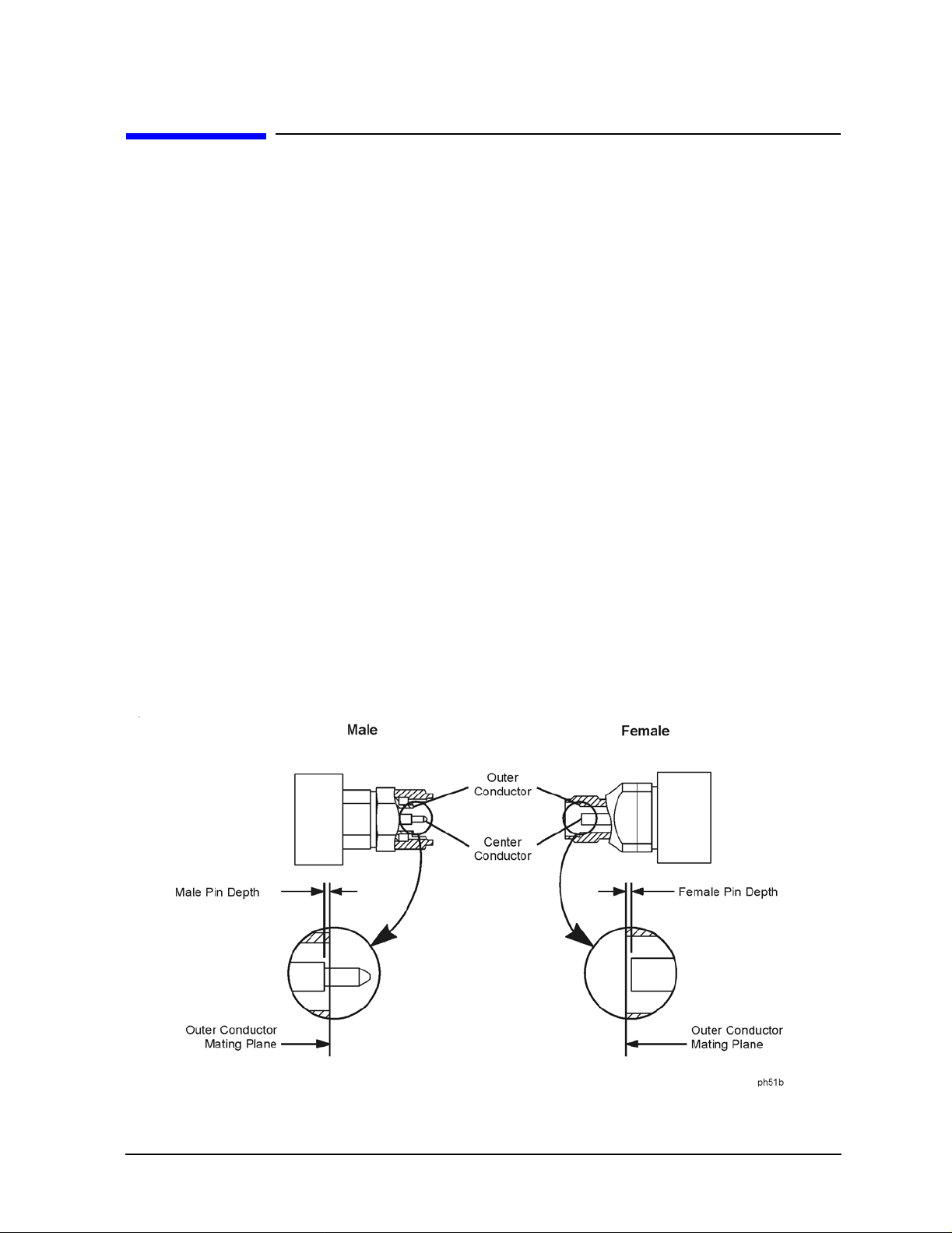
Pin Depth
Pin depth is the distance the center conductor mat ing plane differs from being flush with
the outer co n d uctor mati ng plane. See Figure 2-1. The pin depth of a connector can be in
one of two conditions:
• Protrusion is the condition in which the center conductor extends beyond the outer
conductor mating plane. This condition will indicate a positive value on the connector
gage.
• Recession is the condition in which the center conductor is set back from the outer
conductor mating plane. This condit ion will indicate a negative value on the connector
gage.
Figure 2-1 Connector Pin Depth
85057B 2-3
Specifications
Mechanical Characteristics
Supplemental Characteristics
The following tables list the dimensions of the 50Ω airline and the 25Ω mismatch airline.
These are supplemental mechanical char acteristics , and from these characteri stics you can
calculate expected electrical performance.
Table 2-2 Connector Pin Depths
Connectors
millimeters inches
Attenuators 0.000 to −0.025 0.0000 to −0.001 Airlines
a
a. The relationship between the length of the inner conductor and the
length of the outer conductor determines the airline center conductor
recession. Refer to “Gaging the Airline” on page 3-1 0.
0.0000 to −0.013 0.0000 to −0.0005
Allowable Recession
Using these mechanical dimensions , you can calculat e the expect ed elec trical pe rformance
with the equations in the following publications:
• Nelson, Robert E., and Marlene R. Coryell, "Electrical P arameters of Precisi on, Coaxial,
Air-Dielectric Transmission Lines", U.S. National Bureau of Standards Monograph No.
96.
• Somlo, P.I., "The Computation of Coaxial Line Step Capacitances", IEEE Transactions
on Microwave Theory and Techniques, Volume MTT-15, No. 1, J anuary, 1967.
The measurement method in these publications provides a general idea of the expected
device characteristic impedance. Variations in connector interface s can have a large effect
on your actual electrical measurements.
2-4 85057B

Specifications
Mechanical Characteristics
Airline Characteristics
The dimensions of the airline outer conductor are s hown in Figure 2-2. There are two similar outer conductors in each kit. They are specifically matched to each center conductor.
The dimensions of the 50Ω airline and the 25Ω mismatch airline are shown in Figure 2 -3
and Figure 2-4.
CAUTION The center and outer conductors of the airlines i n this kit have been
mechanically measured and matched. Do not use the center or oute r
conductors provided in th i s kit with a cent er or outer con ductor from an y
other airline. Damage to the airline or attaching connector may result.
Figure 2-2 Airline Outer Conductor
Dimension millimeters inches
D −Diameter 2.400 ±0.0025 0.0945 ±0.0001 L −Length
85057B 2-5
49.991 ±0.025
1.968 ±0.001

Specifications
Mechanical Characteristics
Figure 2-3 50Ω Airline Center Conductor
Dimension millimeters inches
d 1.0423 ±0.003 0.04104 ±0.00012
∆L +0.0025/−0.013 +0.0001/ −0.0005
Figure 2-4 25Ω Mismatch Airline Center Conductor
Dimension millimeters inches
d 1.0423 ±0.008 0.04104 ±0.0003
d
1
l
1
l
2
∆L +0.0025/−0.013 +0.0001/−0.0005
1.58 ±0.005 0.0622 ±0.0002
37.46 ±0.019 1.4748 ±0.0007
6.22 ±0.050 0.2449 ±0.002
2-6 85057B
 Loading...