


User’s and Service Guide
Agilent Technologies 85039B 75Ω
Type-F Calibration Kit
Part Number: 85039-90002
Printed in USA
Print Date: March 2003
Supersedes: July 2002
© Copyright 1997, 2002–2003 Agilent Technologies, Inc.

DOCUMENTATION WARRANTY
THE MATERIAL CONTAINED IN THIS DOCUMENT IS PROVIDED "AS IS," AND IS
SUBJECT TO BEING CHANGED, WITHOUT NOTICE, IN FUTURE EDITIONS.
FURTHER, TO THE MAXIMUM EXTENT PERMITTED BY APPLICABLE LAW,
AGILENT DISCLAIMS ALL WARRANTIES, EITHER EXPRESS OR IMPLIED WITH
REGARD TO THIS MANUAL AND ANY INFORMATION CONTAINED HEREIN,
INCLUDING BUT NOT LIMITED TO THE IMPLIED WARRANTIES OF
MERCHANTABILITY AND FITNESS FOR A PARTICULAR PURPOSE. AGILENT
SHALL NOT BE LIABLE FOR ERRORS OR FOR INCIDENTAL OR CONSEQUENTIAL
DAMAGES IN CONNECTION WITH THE FURNISHING, USE, OR PERFORMANCE
OF THIS DOCUMENT OR ANY INFORMATION CONTAINED HEREIN. SHOULD
AGILENT AND THE USER HAVE A SEPARATE WRITTEN AGREEMENT WITH
WARRANTY TERMS COVERING THE MATERIAL IN THIS DOCUMENT THAT
CONFLICT WITH THESE TERMS, THE WARRANTY TERMS IN THE SEPARATE
AGREEMENT WILL CONTROL
Assistance
Product maintenance agreements and other customer assistance agreements are available
for Agilent products.
For any assistance, contact Agilent Technologies. Refer to Table 5-1 on page 5-3.
ii

1. General Information
Calibration Kit Overview. . . . . . . . . . . . . . . . . . . . . . . . . . . . . . . . . . . . . . . . . . . . . . . . . . . . . . . . . . . . . .1-2
Incoming Inspection. . . . . . . . . . . . . . . . . . . . . . . . . . . . . . . . . . . . . . . . . . . . . . . . . . . . . . . . . . . . . . . . . .1-4
Recording the Device Serial Numbers . . . . . . . . . . . . . . . . . . . . . . . . . . . . . . . . . . . . . . . . . . . . . . . . . . .1-5
Clarifying the Sex of a Connector . . . . . . . . . . . . . . . . . . . . . . . . . . . . . . . . . . . . . . . . . . . . . . . . . . . . . . .1-6
Preventive Maintenance . . . . . . . . . . . . . . . . . . . . . . . . . . . . . . . . . . . . . . . . . . . . . . . . . . . . . . . . . . . . . . 1-6
2. Specifications
Environmental Requirements. . . . . . . . . . . . . . . . . . . . . . . . . . . . . . . . . . . . . . . . . . . . . . . . . . . . . . . . . .2-2
Mechanical Characteristics . . . . . . . . . . . . . . . . . . . . . . . . . . . . . . . . . . . . . . . . . . . . . . . . . . . . . . . . . . . 2-3
Electrical Specifications . . . . . . . . . . . . . . . . . . . . . . . . . . . . . . . . . . . . . . . . . . . . . . . . . . . . . . . . . . . . . .2-3
3. Use, Maintenance, and Care of the Devices
Electrostatic Discharge . . . . . . . . . . . . . . . . . . . . . . . . . . . . . . . . . . . . . . . . . . . . . . . . . . . . . . . . . . . . . . . 3-2
Visual Inspection . . . . . . . . . . . . . . . . . . . . . . . . . . . . . . . . . . . . . . . . . . . . . . . . . . . . . . . . . . . . . . . . . . . .3-3
Cleaning Connectors . . . . . . . . . . . . . . . . . . . . . . . . . . . . . . . . . . . . . . . . . . . . . . . . . . . . . . . . . . . . . . . . . 3-4
Connections . . . . . . . . . . . . . . . . . . . . . . . . . . . . . . . . . . . . . . . . . . . . . . . . . . . . . . . . . . . . . . . . . . . . . . . .3-6
Using the Adapters in Reflection Measurements . . . . . . . . . . . . . . . . . . . . . . . . . . . . . . . . . . . . . . . . .3-10
Using the Adapters in Reflection/Transmission Measurements . . . . . . . . . . . . . . . . . . . . . . . . . . . . .3-11
Handling and Storage . . . . . . . . . . . . . . . . . . . . . . . . . . . . . . . . . . . . . . . . . . . . . . . . . . . . . . . . . . . . . . .3-12
Contents
4. Performance Verification
Introduction . . . . . . . . . . . . . . . . . . . . . . . . . . . . . . . . . . . . . . . . . . . . . . . . . . . . . . . . . . . . . . . . . . . . . . . .4-2
Recertification . . . . . . . . . . . . . . . . . . . . . . . . . . . . . . . . . . . . . . . . . . . . . . . . . . . . . . . . . . . . . . . . . . . . . .4-3
5. Troubleshooting
Troubleshooting Process . . . . . . . . . . . . . . . . . . . . . . . . . . . . . . . . . . . . . . . . . . . . . . . . . . . . . . . . . . . . . . 5-2
Returning a Kit or Device to Agilent . . . . . . . . . . . . . . . . . . . . . . . . . . . . . . . . . . . . . . . . . . . . . . . . . . . . 5-3
6. Replaceable Parts
Introduction . . . . . . . . . . . . . . . . . . . . . . . . . . . . . . . . . . . . . . . . . . . . . . . . . . . . . . . . . . . . . . . . . . . . . . . .6-2
A. Standard Definitions
Standard Class Assignments. . . . . . . . . . . . . . . . . . . . . . . . . . . . . . . . . . . . . . . . . . . . . . . . . . . . . . . . . . .A-2
Nominal Standard Definitions . . . . . . . . . . . . . . . . . . . . . . . . . . . . . . . . . . . . . . . . . . . . . . . . . . . . . . . . .A-4
iii

Contents
iv

1 General Information
85039B 1-1

General Information
Calibration Kit Overview
Calibration Kit Overview
The Agilent 85039B Option M0F, Option 00M, and Option 00F type-F calibration kits are
used to calibrate Agilent network analyzers up to 3 GHz for measurements of components
with 75Ω type-F connectors.
CAUTION If you have an Agilent 85039A 75Ω type-F calibration kit, it should be noted
that the parts are not interchangeable with this kit. Interchanging the parts
will invalidate the calibration definitions.
Kit Contents
The 85039B Option M0F calibration kit contains the following:
• one male and one female 75Ω type-F open termination
• one male and one female 75Ω type-F short termination
• one male and one female 75Ω type-F load
•two 75Ω type-F to 75Ω type-F adapters
•two 75Ω type-F to 75Ω type-N adapters
• a data disk that contains the calibration definitions of the devices in the kit
Refer to Table 6-1 on page 6-3 and Figure 6-1 on page 6-2 for a complete list of kit contents
and their associated part numbers.
The 85039B Option 00M calibration kit contains the following:
•one male 75Ω type-F open termination
•one male 75Ω type-F short termination
•one male 75Ω type-F load
•one 75Ω type-F male to 75Ω type-F male adapter
• a data disk that contains the calibration definitions of the devices in the kit
Refer to Table 6-2 on page 6-4 for a complete list of kit contents and their associated part
numbers.
The 85039B Option 00F calibration kit contains the following:
•one female 75Ω type-F open termination
•one female 75Ω type-F short termination
•one female 75Ω type-F load
•one 75Ω type-F female to 75Ω type-F female adapter
• a data disk that contains the calibration definitions of the devices in the kit
Refer to Table 6-3 on page 6-4 for a complete list of kit contents and their associated part
numbers.
1-2 85039B

General Information
Calibration Kit Overview
Broadband Loads
The broadband loads are metrology-grade, 75Ω terminations that have been optimized for
performance up to 3 GHz. The rugged internal structure provides for highly repeatable
connections. A distributed resistive element on ceramic provides excellent stability and
return loss.
Opens and Shorts
The opens and shorts are built from parts that are machined to the current state-of the-art
precision machining.
The short’s inner conductors have a one-piece construction, common with the shorting
plane. This construction provides for extremely repeatable connections.
The female open has a separate-piece inner conductor that is made from a
low-dielectric-constant plastic to minimize compensation values.
Both the opens and shorts are constructed so that the pin depth can be controlled very
tightly, thereby minimizing phase errors. The opens and shorts have offsets. The lengths of
these offsets are designed so that the difference in phase of their reflection coefficients is
approximately 180 degrees at all frequencies.
Adapters
Like the other devices in the kit, the adapters are built to very tight tolerances to provide
good broadband performance.
Calibration Definitions
The calibration kit must be selected and the calibration definitions for the devices in the
kit installed in the network analyzer prior to performing a calibration. Refer to your
network analyzer user’s guide for instructions on selecting the calibration kit and
performing a calibration.
The calibration definitions can be:
• resident within the analyzer
• loaded from the provided disk
• entered from the front panel
Installation of the Calibration Definitions
The calibration definitions for the kit may be permanently installed in the internal
memory or hard disk of the network analyzer.
If the calibration definitions for the kit are not permanently installed in the network
analyzer, they must be manually entered. Refer to your network analyzer user’s guide for
instructions.
85039B 1- 3

General Information
Incoming Inspection
Equipment Required but Not Supplied
Adapters, a cable set, a torque wrench, ESD protective devices, and various connector
cleaning supplies are not included in the calibration kit but are required to ensure
successful operation of the calibration kit. Refer to Table 6-4 on page 6-5 for ordering
information
Incoming Inspection
Verify that the shipment is complete by referring to Figure 6-1 on page 6-2.
Check for damage. The foam-lined storage case provides protection during shipping.
If the case or any device appears damaged, or if the shipment is incomplete, contact
Agilent. See Table 5-1 on page 5-3. Agilent will arrange for repair or replacement of
incomplete or damaged shipments without waiting for a settlement from the
transportation company.
When you send the kit or device to Agilent, include a service tag (found near the end of this
manual) with the following information:
• your company name and address
• the name of a technical contact person within your company, and the person's complete
phone number
• the model number and serial number of the kit
• the part number and serial number of the device
• the type of service required
•a detailed description of the problem
1-4 85039B

General Information
Recording the Device Serial Numbers
Recording the Device Serial Numbers
In addition to the kit serial number, the devices in this kit are individually serialized
(serial numbers are labeled onto the body of each device). Record these serial numbers in
Table 1-1 for the 85039B Option M0F, in Table 1-2 for the Option 00M, and in Table 1-3 for
the Option 00F. Recording the serial numbers will prevent confusing the devices in this kit
with similar devices in other kits.
Table 1-1 Serial Number Record for 85039B Option M0F
Device Serial Number
Calibration kit
Male broadband load
Female broadband load
Male open
Female open
Male short
Female short
Type-F male to male adapter
Type-F- female to female adapter
Type-F- male to female adapter
_______________________________
_______________________________
_______________________________
_______________________________
_______________________________
_______________________________
_______________________________
_______________________________
_______________________________
_______________________________
Table 1-2 Serial Number Record for 85039B Option 00M
Device Serial Number
Calibration kit
Male broadband load
_______________________________
_______________________________
Male open
Male short
Type-F male to male adapter
85039B 1- 5
_______________________________
_______________________________
_______________________________

General Information
Clarifying the Sex of a Connector
Table 1-3 Serial Number Record for 85039B Option 00F
Device Serial Number
Calibration kit
Female broadband load
Female open
Female short
Type-F- female to female adapter
_______________________________
_______________________________
_______________________________
_______________________________
_______________________________
Clarifying the Sex of a Connector
In this manual, the sex of calibration devices and adapters are referred to in terms of their
connector interface. For example, a male open has a male connector.
However, during a measurement calibration, the network analyzer softkey menus label a
type-F calibration device with reference to the sex of the analyzer’s test port
connector—not the calibration device connector. For example, the label SHORT(F) on the
analyzer’s display refers to the short that is to be connected to the female test port. This
will be a male short from the calibration kit.
Preventive Maintenance
The best techniques for maintaining the integrity of the devices in this kit include:
• routine visual inspection
•cleaning
• proper gaging
• proper connection techniques
All of the above are described in Chapter 3 , “Use, Maintenance, and Care of the Devices.”
Failure to detect and remove dirt or metallic particles on a mating plane surface can
degrade repeatability and accuracy and can damage any connector mated to it. Improper
connections, resulting from pin depth values being out of the limits (see Table 2-2 on page
2-3), or from bad connections, can also damage these devices.
1-6 85039B

2 Specifications
85039B 2-1

Specifications
Environmental Requirements
Environmental Requirements
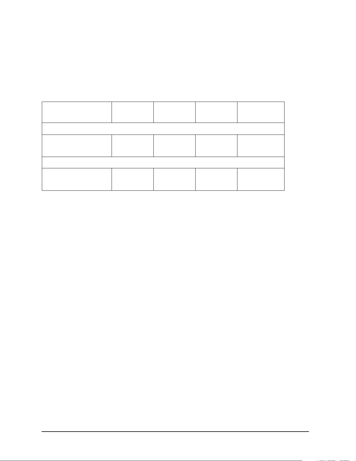
Table 2-1 Environmental Requirements
Parameter Limits
a
Operating Temperature
+15 °C to +35 °C (+59 °F to +95 °F)
Error-Corrected
Temperature Range
Storage Temperature −40 °C to +75 °C (−40 °F to +167 °F)
Altitude:
Operation < 4,500 meters (≈15,000 feet)
Storage < 15,000 meters (≈50,000 feet)
Relative Humidity Always non-Condensing
Operation 0 to 80% (26 °C maximum dry bulb)
Storage 0 to 95%
a. The temperature range over which the calibration standards maintain
conformance to their specifications.
b. The allowable network analyzer ambient temperature drift during
measurement calibration and during measurements when the network
analyzer error correction is turned on. Also, the range over which the
network analyzer maintains its specified performance while correction
is turned on.
b
±1 °C of measurement calibration temperature
Temperature—What to Watch Out For
Changes in temperature can affect electrical characteristics. Therefore, the operating
temperature is a critical factor in performance. During a measurement calibration, the
temperature of the calibration devices must be stable and within the range specified in
Table 2-1.
IMPORTANT Avoid unnecessary handling of the devices during calibration because your
fingers are a heat source.
2-2 85039B

Specifications
Mechanical Characteristics
Mechanical Characteristics
The mechanical characteristics in Table 2-2 apply to the devices in the 85039B 75Ω type-F
calibration kit.
Table 2-2 Mechanical Characteristics
75Ω Device Characteristics
All type-F adapters Pin depth: 0.0 to 0.1 mm (0.0 in to 0.004 in)
All type-N male connectors Pin depth: 5.26 to 5.36 mm (0.207 in to 0.211 in)
All type-N female connectors Pin depth: 5.18 to 5.26 mm (0.204 in to 0.207 in)
Electrical Specifications
The electrical specifications in Table 2-3 apply to the devices in the 85039B 75Ω type-F
calibration kit when connected with an Agilent precision interface.
NOTE The following specifications for female devices assumes a 0.77 mm to 0.86 mm
(0.030 in to 0.034 in) diameter male pin. For calibration kit certification of
female devices a 0.81 mm (0.032 in) diameter male pin will be used.
Table 2-3 Electrical Specifications
75Ω Type-F Device Specification Frequency
Male Load, Female Load: Return Loss ≥ 45 dB (ρ ≤ 0.006)
Return Loss ≥ 38 dB (ρ ≤ 0.013)
a
Male Short
Male Open
Adapters:
Type-F to Type-F Return Loss ≥ 40 dB (ρ ≤ 0.013)
Type-N to Type-F Return Loss ≥ 38 dB (ρ ≤ 0.013)
, Female Short:
a
, Female Open:
±0.60° from nominal
±1.00° from nominal
±0.55° from nominal
±1.30° from nominal
Return Loss ≥ 32 dB (ρ ≤ 0.025)
Return Loss ≥ 32 dB (ρ ≤ 0.025)
dc to ≤ 1 GHz
> 1 to ≤ 3 GHz
dc to ≤ 1 GHz
> 1 to ≤ 3 GHz
dc to ≤ 1 GHz
> 1 to ≤ 3 GHz
dc to ≤ 1 GHz
> 1 to ≤ 3 GHz
dc to ≤ 1 GHz
> 1 to ≤ 3 GHz
a. The specifications for the open and short are given as allowed deviation
from the nominal model as defined in the standard definitions. See Table
2-3.
85039B 2- 3
Specifications
Electrical Specifications
System Performance
The specifications for the system performance are calculated from the electrical
measurement data. The system performance of the devices over the pin diameter range are
not measured as part of the calibration kit certification, but are guaranteed by design.
Only the specifications in Table 2-4 are measured for calibration kit certification.
Table 2-4 System Specifications
Pin Diameter Directivity Source Match Refl.
Tracking
0.77 mm (0.030 in) to
0.86 mm (0.034in):
0.56 mm (0.022 in) to
1.07 mm (0.042 in):
−45 dB
−38 dB
−40 dB
−30 dB
−40 dB
−30 dB
−38 dB
−27 dB
±0.06 dB
±0.24 dB
±0.09 dB
±0.27 dB
Frequency
dc to ≤ 1 GHz
> 1 to ≤ 3 GHz
dc to ≤ 1 GHz
> 1 to ≤ 3 GHz
Certification
Agilent Technologies certifies that this product met its published specifications at the time
of shipment from the factory. Agilent further certifies that its calibration measurements
are traceable to the United States National Institute of Standards and Technology (NIST)
to the extent allowed by the institute’s calibration facility, and to the calibration facilities
of other International Standards Organization members. See “How Agilent Verifies the
Devices in This Kit” on page 4-2 for more information.
2-4 85039B

3 Use, Maintenance, and Care of the
Devices
85039B 3-1
 Loading...