


Errata
This manual may contain references to HP or Hewlett-Packard. Please note that Hewlett-Packard's former test
and measurement, semiconductor products and chemical analysis businesses are now part of Agilent
Technologies. To reduce potential confusion, the only change to product numbers and names has been in the
company name prefix: where a product number/name was HP XXXX the current name/number is now Agilent
XXXX. For example, model number HP8648 is now model number Agilent 8648.
Ce manuel peut contenir des références à <<HP>> ou <<Hewlett-Packard.>> Veuillez noter que les produits de
test et mesure, de semi-conducteur et d'analyse chimique qui avaient fait partie de la société Hewlett-Packard
sont maintenent une partie de la société Agilent Technologies. Pour reduire la confusion potentielle, le seul
changement aux noms de reference a été dans le préfixe de nom de société : là où un nom de référence était HP
XXXX, le nouveau nom de référence est maintenant Agilent XXXX. Par example, le HP 8648 s'appelle
maintenent Agilent 8648.
Diese Gebrauchsanweiseung kann Bezug nehmen auf die Namen HP oder Hewlett-Packard. Bitte beachten Sie,
dass ehemalige Betriebsbereiche von Hewlett-Packard wie HP-Halbleiterprodukte, HP-chemische Analysen
oder HP-Test- und Messwesen nun zu der Firma Agilent Technology gehören. Um Verwirrung zu vermeiden
wurde lediglich bei Produktname und - Nummer der vo laufende Firmenname geändert: Produkte mit dem
Namen/Nummer HP XXXX lauten nun mehr Agilent XXXX. Z.B, das Modell HP 8648 heißt nun Agilent 8648.
Questo manuale potrebbe contenere riferimenti ad HP o Hewlett-Packard. Si noti che le attività precedentemente
gestite da Hewlett-Packard nel campo di Test & Misura, Semiconduttori, ed Analisi Chimica sono ora diventate
parte di Agilent Technologies. Al fine di ridurre il rischio di confusione, l'unica modifica effettuata sui numeri di
prodotto e sui nomi ha riguardato il prefisso con il nome dell'azienda : dove precedentemente compariva "HP
XXXX" compare ora "Agilent XXXX". Ad esempio: il modello HP8648 è ora indicato come Agilent 8648.
Este manual puede hacer referencias a HP o Hewlett Packard. Las organizaciones de Prueba y Medición (Test
and Measurement), Semiconductores (Semiconductor Products) y Análisis Químico (Chemical Analysis) que
pertenecían a Hewlett Packard, ahora forman parte de Agilent Technologies. Para reducir una potencial
confusión, el único cambio en el número de producto y nombre, es el prefijo de la compañía: Si el producto solía
ser HP XXXX, ahora pasa a ser Agilent XXXX. Por ejemplo, el modelo HP8648 es ahora Agilent 8648.
Document Part Number 5971-2668
Printed in the UK September 2004
A

マニュアル・チェンジ
変更
本文中の「HP(YHP)」、または「(横河)ヒューレット・パッカード株式会社」とい
う語句を、「Agilent」、または「アジレント・テクノロジー株式会社」と変更して
ください。
ヒューレット・パッカード社の電子計測、半導体製品、化学分析ビジネス部門は分
離独立し、アジレント・テクノロジー社となりました。
社名変更に伴うお客様の混乱を避けるため、製品番号の接頭部のみ変更しておりま
す。
(例: 旧製品名 HP 4294A は、現在 Agilent 4294A として販売いたしておりま
す。)

Operating and Service Manual
Agilent 8480 Series Coaxial Power Sensors
This manual applies to the following models:
8481A
8482A
8483A
8485A
8487A
8481B
8482B
8481H
8482H
8487D
8485D
8481D
Manufacturing Part Number: 08481-90173
May 2004
© Copyright 2004 Agilent Technologies.

Notice
The material contained in this document is provided "as is," and is
subject to being changed, without notice, in future editions. Further, to
the maximum extent permitted by applicable law, Agilent disclaims all
warranties, either express or implied with regard to this manual and any
information contained herein, including but not limited to the implied
warranties of merchantability and fitness for a particular purpose.
Agilent shall not be liable for errors or for incidental or consequential
damages in connection with the furnishing, use, or performance of this
document or any information contained herein. Should Agilent and the
user have a separate written agreement with warranty terms covering
the material in this document that conflict with these terms, the
warranty terms in the separate agreement will control.
All Rights Reserved. Reproduction, adaptation, or translation without
prior written permission is prohibited, except as allowed under the
copyright laws.
1400 Fountaingrove Parkway, Santa Rosa CA, 95403-1799, USA
ii

War ranty
A copy of the specific warranty terms applicable to your Agilent
Technologies product can be obtained from your local Sales and Service
Office.
Manufacturer's Declaration
This statement is provided to comply with the requirements of the
German Sound Emission Directive, from 18 January 1991.
This product has a sound pressure emission (at the operator position)
< 70 dB(A).
Diese Information steht im Zusammenhang mit den Anforderungen der
Maschinenlärminformationsverordnung vom 18 Januar 1991.
• Sound Pressure Lp < 70 dB(A).
• At Operator Position.
• Normal Operation.
• According to ISO 7779:1988/EN 27779:1991 (Type Test).
Herstellerbescheinigung
• Schalldruckpegel Lp < 70 dB(A).
•Am Arbeitsplatz.
• Normaler Betrieb.
• Nach ISO 7779:1988/EN 27779:1991 (Typprüfung).
iii

iv

Contents
1. Introduction
General Information . . . . . . . . . . . . . . . . . . . . . . . . . . . . . . . . . . . . . . . . . .2
Instruments Covered by Manual. . . . . . . . . . . . . . . . . . . . . . . . . . . . . . .2
Description . . . . . . . . . . . . . . . . . . . . . . . . . . . . . . . . . . . . . . . . . . . . . . . .3
Dimensions . . . . . . . . . . . . . . . . . . . . . . . . . . . . . . . . . . . . . . . . . . . . . . . .5
8480 series, B-models information . . . . . . . . . . . . . . . . . . . . . . . . . . . . .5
Safety Considerations. . . . . . . . . . . . . . . . . . . . . . . . . . . . . . . . . . . . . .6
8480 series, Options . . . . . . . . . . . . . . . . . . . . . . . . . . . . . . . . . . . . . . . . .6
8485A and 8485D option 033 . . . . . . . . . . . . . . . . . . . . . . . . . . . . . . . .6
Accessories Supplied. . . . . . . . . . . . . . . . . . . . . . . . . . . . . . . . . . . . . . .6
8483A 75 ohm sensor . . . . . . . . . . . . . . . . . . . . . . . . . . . . . . . . . . . . . .7
D-model 8480 series sensors (8481D, 8485D, 8485D-033 and 8487D).7
26.5 GHz and 33 GHz Frequency operation (8485A, 8485A-033,
8485D and 8485D-033) . . . . . . . . . . . . . . . . . . . . . . . . . . . . . . . . . . . . .8
50 GHz Frequency operation (8487A and 8487D) . . . . . . . . . . . . . . . .9
Recommended Calibration Interval . . . . . . . . . . . . . . . . . . . . . . . . . . .10
Warranty . . . . . . . . . . . . . . . . . . . . . . . . . . . . . . . . . . . . . . . . . . . . . . .10
8480 Series Power Sensor Specifications . . . . . . . . . . . . . . . . . . . . . . . . .11
Supplemental Characteristics . . . . . . . . . . . . . . . . . . . . . . . . . . . . . . . .18
Installation . . . . . . . . . . . . . . . . . . . . . . . . . . . . . . . . . . . . . . . . . . . . . . . .19
Initial Inspection . . . . . . . . . . . . . . . . . . . . . . . . . . . . . . . . . . . . . . . . . .19
Original Packaging . . . . . . . . . . . . . . . . . . . . . . . . . . . . . . . . . . . . . . .19
Interconnections . . . . . . . . . . . . . . . . . . . . . . . . . . . . . . . . . . . . . . . . .19
Storage and Shipment . . . . . . . . . . . . . . . . . . . . . . . . . . . . . . . . . . . .19
Environment . . . . . . . . . . . . . . . . . . . . . . . . . . . . . . . . . . . . . . . . . . . .19
Operation . . . . . . . . . . . . . . . . . . . . . . . . . . . . . . . . . . . . . . . . . . . . . . . . .20
Environment . . . . . . . . . . . . . . . . . . . . . . . . . . . . . . . . . . . . . . . . . . . . .20
Operating Precautions . . . . . . . . . . . . . . . . . . . . . . . . . . . . . . . . . . . . .20
Power Meter Calibrations. . . . . . . . . . . . . . . . . . . . . . . . . . . . . . . . . .20
Operating Instructions . . . . . . . . . . . . . . . . . . . . . . . . . . . . . . . . . . . .21
1

Contents
Power Measurements . . . . . . . . . . . . . . . . . . . . . . . . . . . . . . . . . . . . 21
Modulation Effects. . . . . . . . . . . . . . . . . . . . . . . . . . . . . . . . . . . . . . . 21
2. General Information
Recommended Test Equipment . . . . . . . . . . . . . . . . . . . . . . . . . . . . . . . 24
Connector Care. . . . . . . . . . . . . . . . . . . . . . . . . . . . . . . . . . . . . . . . . . . . . 25
Torque . . . . . . . . . . . . . . . . . . . . . . . . . . . . . . . . . . . . . . . . . . . . . . . . . . 25
Performance Test . . . . . . . . . . . . . . . . . . . . . . . . . . . . . . . . . . . . . . . . . . . 26
Standing Wave Ratio (SWR) and Reflection Coefficient (Rho)
Performance Test . . . . . . . . . . . . . . . . . . . . . . . . . . . . . . . . . . . . . . . . . 26
Replaceable Parts . . . . . . . . . . . . . . . . . . . . . . . . . . . . . . . . . . . . . . . . . . 30
3. Service
Principles of Operation . . . . . . . . . . . . . . . . . . . . . . . . . . . . . . . . . . . . . . 36
Thermocouple Sensors . . . . . . . . . . . . . . . . . . . . . . . . . . . . . . . . . . . . . 36
Diode Sensors . . . . . . . . . . . . . . . . . . . . . . . . . . . . . . . . . . . . . . . . . . . . 37
Troubleshooting . . . . . . . . . . . . . . . . . . . . . . . . . . . . . . . . . . . . . . . . . . . . 39
Troubleshooting - Eliminating the Power Meter and Sensor Cable. . 40
Troubleshooting - Power Sensors . . . . . . . . . . . . . . . . . . . . . . . . . . . . . 40
A1 Bulkhead (Thermocouple Sensors) . . . . . . . . . . . . . . . . . . . . . . . 40
A1 Bulkhead (Diode Sensors) . . . . . . . . . . . . . . . . . . . . . . . . . . . . . . 41
A2 Power Sensor Board Assembly . . . . . . . . . . . . . . . . . . . . . . . . . . 42
Repair . . . . . . . . . . . . . . . . . . . . . . . . . . . . . . . . . . . . . . . . . . . . . . . . . . . . 43
A1 Bulkhead Assembly. . . . . . . . . . . . . . . . . . . . . . . . . . . . . . . . . . . . . 43
Repair Strategy . . . . . . . . . . . . . . . . . . . . . . . . . . . . . . . . . . . . . . . . . 43
Procedure . . . . . . . . . . . . . . . . . . . . . . . . . . . . . . . . . . . . . . . . . . . . . . 43
A2 Power Sensor Board Assembly . . . . . . . . . . . . . . . . . . . . . . . . . . . . 44
Repair Strategy . . . . . . . . . . . . . . . . . . . . . . . . . . . . . . . . . . . . . . . . . 44
Procedure . . . . . . . . . . . . . . . . . . . . . . . . . . . . . . . . . . . . . . . . . . . . . . 44
2

Contents
FET Balance Adjustment . . . . . . . . . . . . . . . . . . . . . . . . . . . . . . . . . . . . .45
Equipment Required . . . . . . . . . . . . . . . . . . . . . . . . . . . . . . . . . . . . . . .45
Test Description . . . . . . . . . . . . . . . . . . . . . . . . . . . . . . . . . . . . . . . . . . .45
FET Balance Procedure . . . . . . . . . . . . . . . . . . . . . . . . . . . . . . . . . . . . .46
Disassembly / Reassembly Procedures. . . . . . . . . . . . . . . . . . . . . . . . . . .49
Disassembly Procedure . . . . . . . . . . . . . . . . . . . . . . . . . . . . . . . . . . . . .49
Reassembly Procedures . . . . . . . . . . . . . . . . . . . . . . . . . . . . . . . . . . . . .51
A. EPM Series Power Meter (E4418B) Modification
The Material and Tools Required . . . . . . . . . . . . . . . . . . . . . . . . . . . . . . .54
Impact on Warranty . . . . . . . . . . . . . . . . . . . . . . . . . . . . . . . . . . . . . . . .54
Modification Procedure . . . . . . . . . . . . . . . . . . . . . . . . . . . . . . . . . . . . . . .55
B. Bulkhead Assemblies
Bulkhead Parts Lists. . . . . . . . . . . . . . . . . . . . . . . . . . . . . . . . . . . . . . . . .62
Bulkhead Exploded Graphics . . . . . . . . . . . . . . . . . . . . . . . . . . . . . . . . . .69
3

Contents
4

1 Introduction
This Operating and Service Manual contains information about initial
inspection, performance tests, adjustments, operation, troubleshooting
and repair of the Agilent 8480 Series Coaxial Power Sensors.
Chapter 1 1
Introduction
General Information
General Information
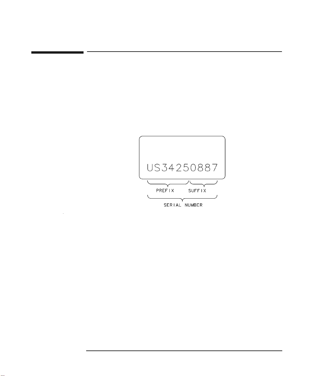
Instruments Covered by Manual
A serial number label is attached to the power sensor. The serial number
has two parts: the prefix (two letters and the first four numbers), and the
suffix (the last four numbers). Refer to the Example Serial Number
shown in Figure 1-1.
Figure 1-1 Example Serial Number
The two letters identify the country in which the unit was manufactured.
"US" represents the USA and "MY" represents Malaysia. The four
numbers of the prefix are a code identifying the date of a major design
change incorporated in your power sensor. The four digit suffix is a
sequential number and, coupled with the prefix, provides a unique
identification for each unit produced.
When seeking information about your power sensor refer to the complete
serial number and include the full prefix number and the suffix number.
For further information concerning a serial number, contact your nearest
Agilent Technologies Sales and Service office.
Chapter 12

Introduction
General Information
Description
The 8480 series power sensors are used for measuring the average power
supplied by an RF or microwave source or device-under-test (DUT). In
use, the Power Sensor is connected to the RF or microwave source and to
a compatible power meter. Suitable and compatible power meters are the
EPM series power meters (E4418B and E4419B), the EPM-P series
power meters (E4416A and E4417A) and the E1416A VXI power meter.
Discontinued and obsolete power meters that are compatible with the
8480 series sensors include the E4418A, E4419A, 435B, 436A, 437B,
438A and 70100A MMS power meter.
The 8480 series power sensors place a 50 ohm load on the RF or
microwave source, except the 8483A which has a 75 ohm load. The power
meter indicates the power dissipated in this load in mW or dBm.
The coaxial power sensors in the 8480 series measure power levels from
-70 dBm to +44 dBm (100 pW to 25 W), at frequencies from 100 kHz to
50 GHz. To cover this wide dynamic power range, both thermocouple and
diode power sensing elements are used. Both types of power sensing
elements have a maximum 50 dB dynamic range. Thermocouple sensors
have a square-law region from -30 dBm to +20 dBm, and with an
attenuator can operate up to +44 dBm. There are three model types of
thermocouple sensors in the 8480 series, covering the complete -30 dBm
to +44 dBm range.
• The A-models cover -30 dBm to +20 dBm.
• The H-models cover from -10 dBm to +35 dBm.
• The B-models cover from 0 dBm to +44 dBm.
Diode detectors (D-models) have the best sensitivity, having an operating
range from -70 dBm to -20 dBm.
Calibration factor (CAL FACTOR) data is provided on a label attached to
the power sensor's cover. Maximum uncertainties of the CAL FACTOR
data are listed in the Specifications section in page 11. This calibration
factor is used to adjust the power meter to suit the particular power
sensor and frequency being measured.
NOTE For the B-models in the 8480 series, calibration factor data is valid only
when the sensor is used with the supplied attenuator.
Chapter 1 3

Introduction
General Information
Figure 1-2 8480 Series Power Sensor Simplified Block Diagram
Cable
Balanced Chopper
Power
Input
Sensing
Element
Thermocouple
or Diode
Thermistor
AC Signal
Feedback
Autozero
Chop Signal
Chop Signal
Figure 1-2 shows a basic power sensor block diagram for both
thermocouple and diode power sensing elements. From the RF or
microwave signal input, both thermocouple and diode detector mounts
generate very low voltages, (on the order of nV or µV). The dc voltage is
proportional to the power from the RF or microwave source. As the dc
voltage is a very low-level, it requires amplification before it can be
transferred to the power meter on the standard cables.
The amplification is provided by an input amplifier assembly that
consists of a balanced chopper (sampling gate) and an AC coupled
low-noise amplifier. The dc voltage is routed on gold wires to the chopper
circuit, which converts the low-level dc voltage to an ac voltage. To do
this, the chopper is uses two field effect transistors (FET's) controlled by
a 220 Hz square-wave generated by in the power meter (the Chop
Signal). The result is an ac output signal proportional to the dc input.
The ac signal is then amplified to a relatively high-level ac signal that
can be routed to the power meter by standard cables.
The autozero signal removes residual error voltages when there is no
input RF or microwave power connected to the sensor input, and
temperature compensation is provided by a thermistor located in
amplifier feedback path.
Chapter 14

General Information
Dimensions
The physical dimensions of the power sensors differ in the model types.
This is due to the additional attenuation used to obtain the high power
performance.
Table 1-1 8480 Series Power Sensor Dimensions (including the RF
Connector)
Introduction
8480 series power
sensor models
A-models 8481A, 8482A and 8483A:
B-models 83 mm x 114 mm x 248 mm (approx. 3.25 in. x 4.50 in. x 9.75 in.)
D-models 8481D and 8485D:
H-models 38 mm wide, 30 mm high, 149 mm long (1.5 in. x 1.2 in. x 5.9 in)
CAUTION Do not disassemble the power sensor. The 8480 series power sensors are
Dimensions
38 mm wide, 30 mm high, 105 mm long (1.5 in. x 1.2 in. x 4.1 in)
8485A and 8487A:
38 mm wide, 30 mm high, 95 mm long (1.5 in. x 1.25 in. x 3.75 in.)
38 mm wide, 30 mm high, 102 mm long (1.5 in. x 1.2 in. x 4.02 in)
8487D:
38 mm wide, 30 mm high, 94 mm long (1.5 in. x 1.2 in. x 3.7 in)
static sensitive and can be easily damaged.
8480 series, B-models information
The 25 W (+44 dBm) power sensor is a calibrated combination of a 30 dB,
25 W attenuator assembly and a sensor assembly. The attenuator and
sensor assemblies are calibrated as a set and must be used together if
specified accuracies are to be obtained.
This combination is referred to as the power sensor.
Chapter 1 5

Introduction
General Information
CAUTION Removal of the D-ring that is on the sensor assembly WILL VOID THE
WARRANTY. The input connector on the sensor has a D-ring to prevent
the sensor from being connected to a high power source when its
attenuator is not attached. The sensor must only be connected to the
power meter for calibration or to the high power attenuator for RF
measurement.
Safety Considerations
The warning that follows is related to possible personal injury.
WARNING The high power attenuator contains a substrate of beryllium
oxide. Beryllium oxide in a powder form is a hazardous material
and may be injurious to your health if inhaled. Do not perform
any operation on the beryllium oxide that might generate dust.
Defective attenuator should be returned to Agilent Technologies
for proper disposal.
8480 series, Options
8485A and 8485D option 033
The 8485A and 8485D power sensors with option 033 are calibrated to
measure power levels in the 50 MHz to 33 GHz frequency range. In all
other respects, they are the same as their respective standard power
sensor.
Accessories Supplied
Accessories are required to connect various power sensors to the power
meter's 50 ohm, Power Reference (1 mW, 50 MHz) output connector
(Type-N (f)).
Chapter 16

Introduction
General Information
8483A 75 ohm sensor
The 8483A sensor is supplied with an adapter, shown in Figure 1-3. This
accessory is a mechanical adapter only, not an impedance transformer,
therefore an impedance mismatch exists that must be taken into
consideration when calibrating the power meter and sensor. The REF
CAL FACTOR, on the power sensor label, has been adjusted for the
impedance mismatch. This REF CAL FACTOR, when used to calibrate
any power meter, will allow calibration to 1.000 mW. The CAL FACTOR,
from the data on the sensor label, should be used for any power
measurements in a 75 ohm system at 50 MHz.
CAUTION Remove the mechanical adapter from the power sensor before connecting
the sensor to a 75 ohm source.
Figure 1-3 Mechanical Adapter (8483A Only)
D-model 8480 series sensors (8481D, 8485D, 8485D-033 and 8487D)
D-model sensors are supplied with a 11708A 30 dB attenuator. To
calibrate a D-model sensor, the 1 mW 50 MHz Power Reference supplied
by the power meter must be reduced to 1µW. The reference attenuator
provides the means to do this.
Chapter 1 7

Introduction
General Information
Table 1-2 11708A 30 dB attenuator characteristics
Characteristic Limits Comments
11708A accuracy at
50 MHz, 25 °C
30 ± 0.05 dB Accuracy traceable to National Institute
of Standards and Technology (NIST),
with a temperature coefficient typically
0.003 dB per °C.
Dimensions Length: 60 mm (2.4 in)
Diameter: 20 mm (0.8 in)
NOTE The 11708A 30 dB attenuator is intended for use only at the 1 mW,
50 MHz power reference of the power meter. Its function as a calibration
reference may be compromised if used for other purposes.
26.5 GHz and 33 GHz Frequency operation (8485A, 8485A-033,
8485D and 8485D-033)
8480 series sensors that operate up to 26.5 GHz and 33 GHz are fitted
with APC-3.5mm (m) connectors as standard. To convert the
APC-3.5mm (m) connector for calibration an adapter (APC-3.5 (f) to
Type-N (m)) is included with the power sensors. Figure 1-4 shows the
parts included with your power sensor.
NOTE The APC-3.5mm to Type-N adapter is intended for use only at the 1 mW,
50 MHz power reference of the power meter. Its function as a calibration
reference may be compromised if used for other purposes.
Chapter 18

General Information
Figure 1-4 8485A, 8485A-033, 8485D, 8485D-033 Sensor Accessories
50 GHz Frequency operation (8487A and 8487D)
8480 series sensors that operate up to 50 GHz are fitted with 2.4mm (m)
connectors as standard. To convert the 2.4mm (m) connector for
calibration, adapter (2.4mm (f) to Type-N (m)) is included with the power
sensors (shown in Figure 1-5).
Introduction
NOTE The 2.4mm to Type-N adapter is intended for use only at the 1 mW,
50 MHz power reference of the power meter. Its function as a calibration
reference may be compromised if used for other purposes.
Chapter 1 9

Introduction
General Information
Figure 1-5 8487A Power Sensor with Adapter
Recommended Calibration Interval
Agilent Technologies recommends a one-year calibration cycle for the
8480 series power sensors.
War ranty
The 8480 series power sensors described in this manual are warranted
and certified as indicated on the inside cover of this manual. Power
sensors are warranted only when they are operated within their
specifications, especially the maximum power handling capability. Any
power sensor returned to Agilent Technologies under warranty will be
examined carefully to determine if the failure was possibly due to
improper use.
Do not open the power sensor. Any attempt to disassemble the power
sensor will void the warranty.
Chapter 110

Introduction
8480 Series Power Sensor Specifications
8480 Series Power Sensor Specifications
NOTE These specifications are valid with EPM and EPM-P Series of power
meters.
The 8480 series thermocouple and diode power sensors provide accuracy,
stability, and SWR over a wide range of frequencies (100 kHz to 50 GHz)
and power levels (-70 dBm to +44 dBm)
NOTE Both Table 1-3 and Table 1-4 show typical uncertainty values to help
estimate measurement uncertainty. These values are only a guideline,
and are not to be used in any accurate uncertainty calculations. Refer to
your power sensor’s specific calibration report for accurate values.
Table 1-3 Typical root sum of squares (rss) uncertainty on the calibration
factor data printed on the power sensor
Freq (MHz) 8482A 8482B 8482H 8483A
0.1 0.8 1.5 0.8 1.3
0.3 0.7 1.4 0.9 1.2
1 0.7 1.4 0.9 1.1
3 0.8 1.5 0.8 1.2
10 0.8 1.5 0.8 1.2
30 0.8 1.5 0.9 1.2
50 0.7 1.4 0.8 1.2
100 0.8 1.4 0.8 1.2
300 0.8 1.4 0.8 1.2
1000 0.8 1.5 0.9 1.2
2000 0.8 1.5 0.8 1.2
4000 0.9 1.5 0.9 -
Chapter 1 11

Introduction
8480 Series Power Sensor Specifications
Table 1-4 Typical root sum of squares (rss) uncertainty on the calibration
factor data printed on the power sensor
Freq (GHz) 8481A 8481B 8481H 8481D 8485A 8485D 8487A 8487D
1 0.7 1.4 0.8 0.8 1.4 1.4 1.4 1.3
2 0.7 1.4 0.8 0.8 1.4 1.4 1.4 1.3
4 0.8 1.5 0.8 0.8 1.7 1.7 1.4 1.4
6 0.9 1.5 0.9 0.9 1.7 1.7 1.5 1.4
8 1.0 1.5 1.0 1.0 1.7 1.7 1.5 1.4
10 1.0 1.6 1.0 1.1 1.9 1.9 1.5 1.5
12 1.1 1.6 1.1 1.2 1.9 1.9 1.6 1.5
14 1.2 1.6 1.2 1.1 2.0 2.0 1.6 1.6
16 1.2 1.7 1.2 1.5 2.0 2.1 1.7 1.7
18 1.5 1.9 1.5 1.7 2.1 2.2 1.7 1.7
22 ----2.62.71.91.9
26.5 ----2.82.82.12.2
28 ----
30 ----
33 ----
34.5 ------2.32.6
37 ------2.42.7
40 ------2.53.0
42 ------2.63.2
44 ------2.93.5
46 ------3.13.8
48 ------2.93.8
50 ------3.85.0
3.1
3.2
3.7
a
a
a
2.9
3.2
3.3
a
a
a
2.2 2.3
2.3 2.4
2.3 2.6
a. These uncertainties only apply to Option 033.
Chapter 112

8480 Series Power Sensor Specifications
Table 1-5 25 Watt sensors, 1 mW to 25 W (0 dBm to +44 dBm)
Introduction
Model Frequency
Range
8481B 10 MHz to
18 GHz
8482B 100 kHz to
4.2 GHz
a. Negligible deviation except for those power ranges noted.
b. For pulses greater than 30 W, the maximum average power (Pa) is limited by the energy per pulse (E) in
W.µs according to Pa = 30-0.02 E.
Maximum
SWR
10 MHz to
2GHz: 1.10
2GHz to
12.4 GHz: 1.18
12.4 GHz to
18 GHz: 1.28
100 kHz to
2GHz: 1.10
2GHz to
4.2 GHz: 1.18
Powe r
Linearity
+35 dBm to
+44 dBm: ±4%
+35 dBm to
+44 dBm: ±4%
a
Maximum
Powe r
0°C to 35°C:
30W avg
35°C to 55°C:
25W avg
0.01 to 5.8 GHz:
500W pk
5.8 to 18 GHz:
125W pk
500W.µs / pulse
0°C to 35°C:
30W avg
35°C to 55°C:
25W avg
0.1 to 4,2 GHz:
500W pk
500W.µs / pulse
b
b
Connector
Type
Type-N(m) Net: 0.8 kg
Type-N(m) Net: 0.8 kg
Table 1-6 3 Watt sensors, 100 µW to 3 W (–10 dBm to +35 dBm)
Wei ght
(1.75 lb)
Shipping:
1.5 kg (3.25 lb)
(1.75 lb)
Shipping:
1.5 kg (3.25 lb)
Model Frequency
Range
8481H 10 MHz to
18 GHz
8482H 100 kHz to
4.2 GHz
a. Negligible deviation except for those power ranges noted.
Maximum
SWR
10 MHz to
8GHz: 1.20
8GHz to
12.4 GHz: 1.25
12.4 GHz to
18 GHz: 1.30
100 kHz to
4.2 GHz: 1.20
Powe r
Linearity
+25 dBm to
+35 dBm: ±5%
+25 dBm to
+35 dBm: ±5%
Chapter 1 13
a
Maximum
Power
3.5W avg,
100W pk
100W.µs / pulse
3.5W avg,
100W pk
100W.µs / pulse
Connector
Type
Type-N(m) Net: 0.2 kg
Type-N(m) Net: 0.2 kg
Wei ght
(0.38 lb)
Shipping:
0.5 kg ( 1.0 lb)
(0.38 lb)
Shipping:
0.5 kg ( 1.0 lb)

Introduction
8480 Series Power Sensor Specifications
Table 1-7 100 mW sensors, 1 µW to 100 mW (–30 dBm to +20 dBm)
Model Frequency
Range
8485A 50 MHz to
26.5 GHz
Option
8485A
-033
8481A 10 MHz to
26.5 MHz to
33 GHz
18 GHz
Maximum
SWR
50 MHz to 100
MHz: 1.15
100 MHz to 2
GHz: 1.10
2 GHz to 12.4
GHz: 1.15
12.4 GHz to 18
GHz: 1.20
18 GHz to 26.5
GHz: 1.25
26.5 GHz to 33
GHz: 1.40
10 MHz to 30
MHz: 1.40
30 MHz to 50
MHz: 1.18
50 MHz to 2
GHz: 1.10
2 GHz to 12.4
GHz: 1.18
12.4 GHz to 18
GHz: 1.28
Pow er
Linearity
+10 dBm to
+20 dBm: ±3%
+10 dBm to
+20 dBm: ±3%
+10 dBm to
+20 dBm: ±3%
a
Maximum
Power
300 mW avg,
15 W pk
30 W.µs / pulse
300 mW avg,
15 W pk
30 W.µs / pulse
300 mW avg,
15 W pk
30 W.µs / pulse
Connector
Type
APC -
3.5mm(m)
APC -
3.5mm(m)
Type-N(m) Net: 0.2 kg
Weight
Net: 0.2 kg
(0.38 lb)
Shipping:
0.5 kg (1.0 lb)
Net: 0.2 kg
(0.38 lb)
Shipping:
0.5 kg (1.0 lb)
(0.38 lb)
Shipping:
0.5 kg (1.0 lb)
8482A 100 kHz to
4.2 GHz
100 kHz to 300
kHz: 1.60
300 kHz to 1
MHz: 1.20
1 MHz to 2
GHz: 1.10
2 GHz to 4.2
GHz: 1.30
+10 dBm to
+20 dBm: ±3%
300 mW avg,
15W pk
30 W.µs / pulse
Type-N(m) Net: 0.2 kg
(0.38 lb)
Shipping: 0.5
kg (1.0 lb)
Chapter 114

8480 Series Power Sensor Specifications
Table 1-7 100 mW sensors, 1 µW to 100 mW (–30 dBm to +20 dBm)
Introduction
Model Frequency
Range
8483A
(75ohm)
8487A 50 MHz to
a. Negligible deviation except for those power ranges noted.
100 kHz to
2GHz
50 GHz
Maximum
SWR
100 kHz to 600
kHz: 1.80
600 kHz to 2
GHz: 1.18
50 MHz to
100 MHz: 1.15
100 MHz to
2GHz: 1.10
2 GHz to
12.4 GHz: 1.15
12.4 GHz to
18 GHz: 1.20
18 GHz to
26.5 GHz: 1.25
26.5 GHz to
40 GHz: 1.30
40 GHz to
50 GHz: 1.50
Pow er
Linearity
+10 dBm to
+20 dBm: ±3%
+10 dBm to
+20 dBm: ±3%
a
Maximum
Power
300 mW avg,
10W pk
300 mW avg,
15W pk
30 W.µs / pulse
Connector
Type
Type-N(m)
(75 ohm)
2.4 mm (m) Net: 0.14 kg
Weight
Net: 0.2 kg
(0.38 lb)
Shipping: 0.5
kg (1.0 lb)
(0.28 lb)
Shipping: 0.5
kg (1.0 lb)
Chapter 1 15

Introduction
8480 Series Power Sensor Specifications
Table 1-8 High sensitivity sensors, 100 pW to 10 µW (–70 dBm to –20 dBm)
Model Frequency
Range
b
b
10 MHz to
18 GHz
50 MHz to
26.5 GHz
50 MHz to
33 GHz
8481D
8485D
Option
8485D
-033
Maximum SWR
10 MHz to
30 MHz: 1.40
30 MHz to 4 GHz:
1.15
4 GHz to 10 GHz:
1.20
10 GHz to
15 GHz: 1.30
15 GHz to
18 GHz: 1.35
50 MHz to
100 MHz: 1.19
100 MHz to
4GHz: 1.15
4 GHz to 12 GHz:
1.19
12 GHz to
18 GHz: 1.25
18 GHz to
26.5 GHz: 1.29
26.5 GHz to
33 GHz: 1.35
Power
Linearity
-30 dBm to
-20 dBm: ±1%
-30 dBm to
-20 dBm: ±2%
-30 dBm to
-20 dBm: ±2%
Maximum
Power
a
100 mW avg,
100 mW pk
100 mW avg,
100 mW pk
100 mW avg,
100 mW pk
Connector
Type
Type-N (m) Net: 0.16 kg
APC -
3.5mm (m)
APC -
3.5mm (m)
Weight
(0.37 lb)
Shipping:
0.5 kg (1.0 lb)
Net: 0.2 kg
(0.38 lb)
Shipping:
0.5 kg (1.0 lb)
Net: 0.2 kg
(0.38 lb)
Shipping:
0.5 kg (1.0 lb)
Chapter 116
 Loading...