


User's
Guide
HP
83485A/B
Optical/Electrical
Plug-In Module

HP
part
number:
Printed
Notice
without
to
this
in
US
.
The
information
notice
material,
A
merchantability
not
be
liable
for
damages
in
connection
material.
83485-90056
June
.
Hewlett-P
including
and
errors
1999
contained
ackard
tness
contained
with
but
for
the
in
makes
not
limited
a
particular
herein
furnishing,
this
no
or
document
to
warranty
,
the
implied
purpose
for
.
incidental
performance
is
subject
of
any
kind
warranties
Hewlett-P
or
consequential
,
or
use
to
change
with
ackard
of
this
regard
of
shall
Restricted
Rights
Government
of
the
Rights
252.227-7013
Commercial
other
agencies
Legend.
is
subject
in
T
echnical
for
DOD
Computer
.
Use
to
restrictions
Data
agencies
Software
,
duplication,
as
and
Computer
,
and
subparagraphs
Restricted
set
or
forth
Software
Rights
disclosure
in
subparagraph
clause
(c)
(1)
clause
at
by
and
F
the
at
(c)
AR
52.227-19
U
DF
(2)
.S
(c)
.
(1)
ARS
of
(ii)
the
for
c
Copyright Hewlett-Packard Company 1999
All Rights Reserved. Reproduction, adaptation, or translation without prior
written permission is prohibited, except as allowed under the copyright laws
.

Safety
The
following safety
yourself
Symbols
with each
symbols are
of the
symbols
used
and
throughout
its
meaning
this
before
manual.
operating
F
amiliarize
this
instrument.
The
C
AU
TI
ON
caution
procedure
damage
sign
until the
The
W
A
R
N
I
N
G
warning
procedure
in
injury
indicated
sign
which, if
to or
destruction
indicated
sign
which, if
or
loss
conditions
denotes a
not correctly
conditions
denotes
not correctly
of
life
.
are
hazard to
performed or
of
the
instrument.
a
life-threatening
Do
not
proceed
fully
understood
the
instrument.
Do
are
fully
understood
performed or
beyond
and
adhered
not
proceed
hazard.
adhered
a
warning
met.
It
It
calls
to
and
,
could
met.
calls
to
attention
result
beyond
attention
,
could
sign
until
to
in
a
caution
result
the
to
a
a
Instruction
Manual
L
The
instruction
for
the
user to
manual
refer
to
symbol.
the
The
instructions
product
in
the
is
marked
manual.
with
this symbol
when
it
is
necessary
iii

General
Safety Considerations
W
A
R
N
I
N
G
Before
grounded
socket
Any
outside
can
W
A
R
N
I
N
G
There
personal
Any
instrument
trained
W
A
R
N
I
N
G
If
equipment
condition
C
A
U
T
I
O
N
Before
has
F
the
C
A
U
T
I
O
N
Electrostatic
inside
warranty
this
outlet
interruption
result
are
adjustments
service
this
instrument
this
been
ailure
to
instrument
the
instrument
through
provided
the
instrument,
in
personal
many
injury
.
with
could
(in
which
instrument
adapted
set
the
when
discharge
instrument.
.
is
switched
the
protective
with
protective
of
the
protective
or
disconnection
injury
.
points
Be
in
extremely
or
service
the
instrument
procedures
protective covers
personnel.
is
not
used
as
be
impaired.
all
to
ac
means
is
the
power
the
(ESD)
Repair
switched
voltage
input to
ac
power
on
of
for
on
,
make
conductor
earth
(grounding)
careful.
that
removed should
specied,
This
instrument
protection
on,
make
of
the ac
the correct
cable
is plugged
or
near
input
damage
due
of
of
the
which
require
the
are
sure
power
to
sure
it
has
the
ac
contact.
conductor
protective
can,
if
operation
be performed
protection
must
be
intact)
its
primary
source
.
voltage
could
in.
connectors
misuse
been
power
,
inside
cable
earth
contacted,
provided
used
in
only
.
power
cause
can
damage
is
not
covered
properly
to
or
terminal
cause
of
the
only by
by
a
normal
circuitry
damage
circuits
under
a
the
to
Before
center
properly
connecting
and
outer
grounded,
any
conductors
and
touching any connector
iv
cable
should
.
to
of
the
the
touch
electrical
cable
together
the
frame
input,
.
of
momentarily
P
ersonnel
the
instrument
short
should
the
be
before

Assistance
Product
are
F
or assistance
maintenance agreements
available for
Hewlett-Packard
, contact
Headquarters
Hewlett-P
ackard
Compan
y
19320
Cupertino
(800)
752-0900
Pruneridge
A
venue
,
CA
95014
U
.S.A.
Colorado
Hewlett-P
ackard
Compan
y
24
Inverness
Place
,
East
Englewood,
(303)
New
Hewlett-P
150
Rockawa
(201)
649-5000
Jersey
ackard
Green
y
,
586-5400
CO
Pond
NJ
80112
Compan
Road
07866
y
Headquarters
Hewlett-P
ackard
S.A.
150,
Route
du
Nant-d'A
vril
1217
Me
yrin
2/Geneva
Switzerland
(41
22)
780.8111
Great Britain
Hewlett-Packard Ltd.
Eskdale Road, Winnersh T
riangle
Wokingham, Berkshire RG11 5DZ
your nearest
Hewlett-Packard
U.S.
FIELD OPERA
California,
Hewlett-P
ackard
301
East
Evelyn
Mountain
(415)
694-2000
Georgia
Hewlett-P
ackard
2000
South
Atlanta,
GA
(404)
955-1500
T
exas
Hewlett-P
ackard
930
East
Campbell Road
Richardson,
(214)
231-6101
EUROPEAN
France
Hewlett-P
ackard
1
A
venue
Zone
D'Activite
F-91947 L
es
France
(33
1)
69
and other
products.
Hewlett-P
Sales and
Northern
Compan
View
,
CA
94041
Compan
P
ark
Place
30339
Compan
TX
75081
FIELD
OPERA
France
Du
Canada
De
Courtaboeuf
Ulis
Cedex
82
60
60
customer
ackard
Service
TIONS
y
y
y
TIONS
assistance
Sales
Oces
California,
Hewlett-P
1421
Fullerton,
(714)
Illinois
Hewlett-P
5201
Rolling
(708)
Germany
Hewlett-P
Hewlett-P
61352
Germany
(+49
and
ackard
South
CA
999-6700
ackard
T
ollview
Meadows,
342-2000
ackard
ackard
Bad
Homburg
6172)
agreements
Service
Southern
Compan
Manhatten
92631
Compan
Drive
IL
GmbH
Strasse
16-0
y
A
y
60008
ve
.
Oce
.
v

Hewlett-Packard
Sales
and
Service
Oces
(continued)
Headquarters
Hewlett-P
ackard
3495
Deer Creek
P
alo
Alto
,
California
(415)
857-5027
China
China Hewlett-P
38
Bei
San
Huan
Shuang
Y
u
Shu
Hai
Dian
District
Beijing,
China
(86
1)
256-6888
T
aiwan
Hewlett-P
ackard
8th
Floor
,
H-P
337
Fu
Hsing North
T
aipei,
T
aiwan
(886
2)
712-0404
Compan
y
Rd.
94304-1316
ackard Compan
X1
Road
T
aiwan
Building
Road
INTERCON
Australia
Hewlett-P
31-41
Blackburn,
(61
Japan
Yokogawa-Hewlett-P
y
1-27-15
Kanagawa
(81
FIELD
ackard
Joseph Street
Victoria
3)
895-2895
Y
abe
229,
427)
59-1311
OPERA
Australia
3130
ackard Ltd.
,
Sagamihara
Japan
TIONS
Ltd.
Canada
Hewlett-P
ackard
17500
South Service
T
rans-Canada
Kirkland,
Quebec
Canada
(514)
697-4232
Singapore
Hewlett-Packard
Pte
.
Ltd.
Alexandra
singapore
(65)
P
.O
9115
271-9444
.
Ltd.
Road
Highwa
y
H9J
Singapore Ltd.
Box
87
2X8
vi

W
arranty
This
Hewlett-Packard
material
During
either
F
or warranty
facility
to
the
and
and workmanship
the warranty
repair or
designated by
Hewlett-Packard
product
taxes
for
instrument product
period, Hewlett-P
replace products
service or
Hewlett-P
and
to
Buyer
.
However
products
returned
for a
repair,
this
ackard.
Hewlett-P
,
is
period
of
one
ackard Company
which prove
product
Buyer
ackard
Buyer
to
shall
shall
Hewlett-P
warranted
year
from
to
be
defective
must
be
shall
prepay
pay
shipping
pay
all
shipping
ackard
from
against
date
will,
returned
shipping
charges
another
defects
of
shipment.
at
its
.
to
a
charges
country
in
option,
service
charges
to
return
,
duties
,
.
Hewlett-P
Hewlett-P
instructions
does
rmware
Limit
The
or inadequate
ackard
ackard
not
warrant
will
a
tion
foregoing
warrants
for use
when
properly
that
be
uninterrupted
of
W
arranty
warranty
maintenance
the operation
interfacing, unauthorized
environmental specications
or
maintenance
NO
OTHER
SPECIFICALL
MERCHANT
Ex
clusive
THE
REMEDIES
REMEDIES
DIRECT
D
,
AMAGES, WHETHER B
.
W
ARRANTY
Y
DISCLAIMS
ABILITY
Remedies
PRO
.
HEWLETT-P
INDIRECT
AND
VIDED
,
SPECIAL,
LEGAL THEORY.
that
its
software
with an
instrument will
installed
on that
of the
or error-free
shall
not
apply
by
Buyer
,
modication
for the
IS
EXPRESSED
THE
FITNESS
HEREIN
A
CKARD
product,
IMPLIED
FOR
ARE
SHALL
INCIDENT
ASED ON CONTRA
and
rmware
execute its
instrument. Hewlett-P
instrument,
or
.
to
defects
Buyer-supplied
or
misuse
OR
W
ARRANTIES
A
P
BUYER'S
NOT
AL,
CT,TORT
resulting
software
,
operation
or
improper
IMPLIED
.
HEWLETT-P
ARTICULAR
SOLE
BE LIABLE
OR
CONSEQUENTIAL
, OR ANY OTHER
designated
programming
software
from
or
outside
site
preparation
OF
PURPOSE.
AND
EXCLUSIVE
FOR ANY
by
ackard
,
or
improper
of
the
A
CKARD
vii


Contents
1.
The
Ordering
Men
The
F
ront
Getting
Installing
T
Cleaning
T
To
T
T
2.
Channel
Displa
NN
N
N
Display
N
N
N
N
Scale
N
N
N
N
Offset
N
N
N
N
Bandwidth/Wavelength.
N
N
N
NN
Channel
N
NN
N
External
N
N
N
N
Calibrate
Instrument
information .
uand
rigger
o
o
o
N
N
N
N
N
N
N
N
NN
N
N
N
N
Key
Con
HP 83485A/B
panel
of
the
b
the
.
.
.
Connections
clean a
clean
test
test
N
N
N
N
N
N
N
N
N
N
N
N
N
N
N
N
N
N
N
N
N
NN
NN
N
N
N
N
N
N
N
N
N
N
N
N
N
N
N
N
N
non-lensed connector
an
adapter
insertion
return
Setup
ying
N
N
N
N
N
N
N
N
N
N
N
N
N
NN
N
N
N
N
N
N
N
N
N
N
N
N
N
N
N
N
N
N
NN
Menu
the
N
N
N
N
N
N
.
.
.
.
.
N
N
N
.
.
N
N
N
N
N
N
N
N
N
N
N
N
N
N
N
N
N
N
N
N
N
N
N
N
N
N
N
NN
NN
N
autoscale
N
N
N
NN
NN
NN
NN
N
N
N
N
N
scale
NN
NN
N
N
N
N
N
N
N
.
N
N
N
at
a
Glance
.
v
en
tions
Optical/Electrical
the
plug-in
est
p
erformance
plug-in
.
loss
Channel
.
.
.
NN
NN
N
N
N
N
N
N
N
N
N
N
N
.
N
N
N
N
N
N
N
N
N
.
loss
.
.
.
N
N
N
N
N
N
N
N
N
N
N
NN
.
.
.
for
.
.
.
.
N
N
N
N
N
N
N
N
N
N
N
N
NN
NN
NN
.
mo
dule
.
.
Accurate
.
.
.
.
.
.
Setup
.
.
.
.
.
.
N
N
N
N
N
N
N
NN
NN
N
.
N
N
N
N
N
N
N
N
N
.
.
.
.
N
N
.
.
mo
.
.
.
.
.
.
.
N
N
N
.
.
.
.
N
N
.
.
.
.
.
.
.
.
.
N
N
N
.
.
.
.
.
.
dule
.
.
.
.
.
.
men
.
.
.
N
N
N
N
.
.
.
.
.
.
.
.
.
.
.
.
.
Plug-In
.
.
.
.
.
.
.
.
.
.
.
.
.
.
.
.
.
.
.
Measuremen
. .
.
.
.
.
.
.
.
.
.
.
.
.
.
.
.
.
.
.
us
.
.
.
.
.
.
.
.
.
.
.
.
.
. .
.
.
.
.
.
. .
. .
.
.
.
.
.
.
.
.
.
.
.
.
. .
. .
.
.
Mo
.
.
.
.
.
.
.
.
.
.
. .
.
.
.
ts
.
.
dule
.
.
.
.
.
.
.
.
.
.
.
.
.
.
. .
.
.
.
.
1-4
.
.
. .
.
.
.
.
.
.
. .
.
.
.
.
.
.
.
.
.
.
.
.
.
.
. .
.
.
.
.
.
.
.
.
.
.
.
.
.
.
.
.
.
.
.
.
.
.
.
.
.
. .
.
.
1-6
.
1-8
.
1-10
1-11
.
1-11
.
1-12
.
1-13
.
1-15
1-16
.
1-16
.
1-17
.
2-4
.
2-5
.
2-6
.
2-7
.
2-7
.
2-9
.
2-9
.
2-11
3.
Calibration Overview
F
actory Calibrations
Mainframe
O/E F
User Calibrations|Optical and Electrical
O/E User-W
Plug-in Mo dule V
Oset Zero Calibration .
Dark Calibration . . . . . . . .
Channel Skew Calibration
Calibration
actory W
avelength Calibration .
. .
. .
.
.
avelength Calibration
ertical Calibration
. . . . .
.
.
.
.
.
.
.
.
.
.
.
.
. . . . . . . .
.
. . . . . . . .
. . .
. . . . . . . . .
. . . . . . . . .
. . . . . . .
.
.
.
.
.
.
.
.
. . .
. . . .
. . . . . .
. . . . . .
.
. .
.
.
.
Contents-1
3-4
3-4
3-6
3-7
3-9
3-11
3-12
3-14
3-15
Prob
External
Complete
4.
Specications
Sp
ecications
V
ertical
En
Characteristics
T
rigger
Declaration
5.
In
Case
If
the
If
the plug-in
Error
Index
e
Calibration
Scale
Calibration
sp
ecications
vironmen
input
of
of
Diculty
mainframe
does
Messages .
.
.
.
.
Summary
and
Regulatory
.
.
.
.
tal
sp
ecications
.
.
.
c
haracteristics
Conformit
do
es
not
not
op
. .
.
.
.
.
y
erate
. .
.
.
.
.
.
.
Information
.
.
.
.
.
.
.
.
.
.
.
op
erate
.
.
.
.
.
.
.
.
.
.
. .
. .
.
.
.
.
.
.
.
..
..
..
.
.
.
.
.
.
.
.
.
.
.
.
.
.
.
. .
. .
. .
.
.
.
.
. .
. .
. .
. .
.
.
.
.
.
. .
. .
. .
.
.
. .
. .
. .
. .
.
.
.
.
.
.
. .
. .
. .
.
.
.
.
. .
. .
. .
. .
.
.
.
.
.
.
.
.
.
.
.
.
.
.
.
.
.
.
.
.
.
.
.
.
.
.
.
.
.
.
.
.
3-16
3-18
.
3-20
.
4-3
.
4-3
.
4-9
.
4-10
.
4-10
4-11
.
5-3
.
5-4
.
5-6
Contents-2

Figures
1-1.
Front panel
2-1.
Optical Channel
2-2.
Electrical Channel
2-3.
A typical
3-1.
Current Frame
3-2.
Plug-in calibration
3-3.
Oset Zero
3-4.
Dark
3-5.
Electrical
3-6.
External
T
ables
of the
Cal Status
Calibration
calibration
Channel
Scale
plug-in
Setup menu.
Setup menu.
display.
1Temp
condition .
menu
.
menu
.
Calibrate
Menu
.
.
module
.
.
.
.
.
.
.
.
.
.
.
Menu
.
.
.
.
.
.
..
.
.
.
.
.
.
.
.
.
.
.
.
.
.
.
.
.
.
.
.
.
.
.
1-10
.
.
.
.
.
.
.
.
.
.
.
.
2-3
.
.
.
.
.
.
.
.
.
.
.
.
2-4
.
.
.
.
.
.
.
.
.
.
.
.
2-13
.
.
.
.
.
.
.
.
.
.
.
.
3-5
.
.
.
.
.
.
.
.
.
.
.
. 3-10
.
.
.
.
.
.
.
.
.
.
..
3-13
.
.
.
.
.
.
.
.
.
.
.
.
3-15
.
.
.
.
.
.
.
.
.
.
.
.
3-17
.
.
.
.
.
.
.
.
.
.
.
.
3-19
3-1.
F
actory
3-2.
Optical
3-3.
Miscellaneous
3-4.
Complete
Calibration
and
Electrical
User
Calibration
Summary
Channel
Calibration
Summary
.
.
.
.
.
.
User
Calibration Summary
Summary
.
.
..
.
..
.
..
..
..
..
..
..
..
..
.
..
..
.
.
.
.
.
.
Contents-3
3-4
3-8
3-9
3-20

Contents
1
The
Instrument
Glance
at
a
The
What
This
options
the
the
lightwave
Instrument at
you'll nd
chapter
ke
front
describes:
and
accessories
y
conventions
panel,
connector
in this
rear
chapter
used
panel
care
in this
and
manual
ke
ys that
a Glance
do
not
displa
y
menus
on
the
screen
Understanding
The
C
A
U
T
I
O
N
input
Therefore
connectors
momentarily
A
void
touching
the
frame
earth-grounded
The HP
measurement
selectable
oscilloscope
greater
The
HP
the information
circuits
,
avoid
.
Before
short
of
the
83485A
bandwidth
noise
delity
83485B
in this
can
be
damaged
applying
static
connecting
the
center
the
front-panel
instrument.
to
prevent
optical/electrical
channels
,
one
settings
performance
for
high
speed
optical/electrical
chapter
will
by
discharges
any
coaxial
and
outer conductors
input connectors
Be sure
buildup
that the
of
static charge
plug-in
optical
.
In
the
is
excellent,
signals
and
lower
.
plug-in
help
you
successfully
electrostatic
to
the
cable
instrument
module
one
electrical.
bandwidth
while
module
operate
discharge
front-panel
to
the
connectors
of
the
cable
without
rst
is
.
incorporates
Each
modes
the
20
GHz
incorporates
the
instrument.
(ESD).
input
,
together
touching
properly
two
channel
of
12.4
mode
a
30
has
allows
GHz
.
two
GHz,
optical measurement channel and a 40 GHz electrical channel. The electrical
channel also has a reduced-bandwidth setting of 18 GHz for improved noise
performance.
The integrated optical channel reduces mismatch loss variation by eliminating
signal distorting cables and connectors associated with the use of external
receivers in order to accurately characterize
optical waveforms
. The optical
1-2

The
Instrument
at
a
Glance
channel
display
measurement
provides
1600
The
SONET/SDH
(formerly
requirements
a
front-panel
nm
HP
is
calibrated
of
the
for
consistent
using
83485A
reference
CCITT)
of
for
button
Bessel-Thomson
channel
potential
the
and
The
path,
no
designed
The
on
testing,
or
by
variability
lter
when
SONET/SDH
HP
83485B
similar
industry
to
electrical
tributary
for
for
general
a
very
to
standards
meet
measurement
electrical
measurements
at
1310
received
the
optical
signal's
accuracy
a
source
and
optical/electrical
receiver
G.957
and
transmitter
or
issuing
lter
is
inserted
repeatable
and
the
alternating
compliance
optical/electrical
the
HP
83485A
exist
anticipated
signals
with
purpose
measurements
nm
and
waveform
average
at
power
plug-in
that
Bellcore
compliance
an
HP-IB
into
HP
microwave
time
wasted
between
testing.
plug-in
,
for
for
10
Gb/s
future
channel
,to
evaluate
HP's
1550
nm
in
optical
power
.
In
any
wavelength
meter
.
module
is
measured
GR-253-CORE
testing.
command,
or
removed
switch.
by
manually
high-delity
module
10
Gb/s transmitter
testing,
standards
may
be
.
used
receiver
wide range
.
to
provide
power
addition,
between
also
is
to
comply
frequency
By
either
a
fourth-order
from
The
waveform
includes
the
HP 83485B
to
perform
performance
of
external
both
accurate
units
and
the
User
1200
a
calibrated
to
ITU-TS
response
pressing
the
measurement
switch
inserting
removes
and
characterization
a
reference
test. Although
has been
measurements
in
optical
Cal
feature
nm
and
the
removing
receiver
transceiver
receivers
,
The
HP
83485A
12.4 GHz
12.4 GHz
Switchable SDH/SONET
Trigger channel
The
HP 83485B
30
GHz
18
GHz
Switchable SDH/SONET lter for transceiver performance testing
Trigger channel input to the mainframe
optical/electrical
and
20
GHz
optical
and
20
GHz
electrical
input
to
optical/electrical plug-in
optical
and
channel
40
GHz
electrical
lter
the
plug-in
channel
channel
for
transceiver
mainframe
channel
module provides:
compliance
module
provides:
testing
1-3

HP
HP
83485A
83485B
options
options
Ordering
Option
Option
Option
030
032
034
receiver
Option
Option
Option
Option
Option
Option
Option
Option
0B
W
0B1
0B0
UK6
001
002
040
050
information
Built-in
Built-in
Built-in
HP
A
Deletes
Measured
Latest
Latest
F
ourth order
Fifth
STM-1/OC-3
STM-4/OC-12
STM-16/OC-48
83485A/B
dditional
set
the
performance
operating
operating system
order lter/10
Service
of
user
lter/10 Gb/s
155
Mb/s
622
Mb/s
2.488
Gb/s
Guide
user
documentation
documentation
data
system
rmware
rmware for
reference
Gb/s reference
SDH/SONET
reference receiver
SDH/SONET reference
SDH/SONET reference
for the
HP 83480A
the
HP
54750A
receiver
receiver
receiver
mainframe
mainframe
Optical
interface
connector
options
Option
Option
Option
Option
Option
Option
1-4
011
Diamond
012
FC/PC
013
DIN
014
ST
015
Biconic
017 SC
HMS-10/HP
47256

The
Instrument
at
Ordering information
a
Glance
Optional
accessories
HP
54006A
HP
54008A
HP
54118A
HP
10086A
SMA
SMA
APC
3.5 (f-f)
APC
2.4 (f-f)
APC
2.4 to
HP
81000AI Diamond
HP
81000FI FC/PC/SPC/APC
HP
81000KI
HP
81000SI
HP
81000VI
HP
81000WI
6
GHz divider
22
ns delay
500
MHz to
ECL
terminator
(f-f)
adapter
,HP
50 termination,
adapter,
adapter,
3.5 (f-f)
SC
connector
DIN
47256/4108.6
ST
connector
Biconic
probe
line
18 GHz
part number
HP part
HP part
trigger
1250-1158
number 1810-0118,
number
HP 11900B
adapter,
HP
11901B
HMS-10/HP connector
connector
interface
connector
interface
1250-1749
interface
interface
interface
1
each
1-5
Menu
The
keys labeled
Pressing
along
the right
menus
.
and
some front-panel
Key
Trigger,
side of
the display
Conventions
Disk,
and
Run
are
keys accesses
screen.
menus
These
all
examples
of
functions
menus
of
front-panel
that
are
called
are
softkey
keys
.
displayed
Softkey
front-panel
unlabeled
unlabeled
A
front-panel
shifted
next
Throughout
key
key
the
are
function,
key)
A
function
highlighted. T
An On
N
N
N
N
TestOn.
A softkey
functions
until
Freerun is highlighted. A choices softkey will be indicated throughout this
manual as:
When some softkeys
a
such as
menus list
keys.
key immediately
keys
dditional
front-panel
indicated
softkey
N
N
NN
NN
measurement will be made and the result will be provided. Some softkeys
functions
function,
to
the
label,
for
label,
for
for
will
be
with
on
or
O
NN
N
N
such as
.
In
Triggered
NNNNN
NNNNNNNNNNNNNN
N
Offset
keys
desired
this
shown
or
NNNNNNNNNNN
Sweep Triggered Freerun
functions other
T
o
activate
next
next
to
the
annotation
are
listed
.
These
press the
manual
example
example
key
by
the front-panel
example
On
o.
o
turn
softkey
this
is
highlighted,
NNNNNNNNNNNNNNNNNNNNNNNNN
require the entry of a numeric value
functions
blue front-panel
function.
front-panel
,
4
Timebase
N
N
N
N
N
N
N
N
N
N
N
N
Mask
,
pressed
as
and O
To
the
function
NN
NN
NN
NN
N
Sweep Triggered
case
,suchas
and
the
Local function
5
,
4
Shift
in its
turn the
function
N
N
N
N
N
N
N
N
N
N
N
N
N
N
N
you
could
NNNNNNNNNNNNNNNNNNNNNNNNN
than those
a
function
to
in
blue
5
.
N
N
N
N
N
N
N
N
N
N
N
NN
Align
which
4
Shift
4
Lo
cal
label
function
will
N
NN
NN
NN
NN
N
N
N
N
choose
or
choose
NNNNNNNNNNNNNNNNNNNNNNNNN
Calibrate probe
the
annotation
on
type
are
called
keys are
Softkeys
N
N
N
N
N
N
N
.
The
menu
5
key
5
.
can
o,
press
be
indicated
N
N
N
N
N
N
N
N
N
N
N
N
N
NN
Freerun
NNNNNNNNNN
on
the
the
above
are
softkeys
followed
(above
be
on,
NN
NN
NN
N
N
N
Triggered
Freerun
Triggered
NNNNNNNNNNNNNNNNNNNNNN
accessed
softkey
display
shifted
Shift key
indicated by
indicated by
is
selected.
the
used
press
the
softkey
throughout
N
N
N
N
N
N
N
N
N
N
directly
menu,
on
the
are
and
below
functions
and the
displayed
by the
4
Stop/Single
to
turn
the
softkey
so
oers
you
by
pressing the
by
pressing
.
, are pressed the rst time
.T
press
screen.
called
some
.
front-panel
a
box
shading on
depend
Shifted
shaded
5
the
softkey's
so
O
is
this
a
choice
the
o enter or change the
by
the
the
The
softkeys
of
the
To
activate a
around
the
on
functions
shifted
front-panel
On
is
highlighted.
manual
of
softkey
softkey
.
the
as:
key
until
,
,
1-6

value
,
section.
use
the
general
purpose
knob
located
below
The
Menu and
the
front-panel
Instrument
Key
at
a
Glance
Conventions
Measure
1-7

The
HP
83485A/B
ule
The
HP 83485A/B
modules
features
Integrated, calibrated
Optical channel
Electrical measurement
2.5
Both
available for
are:
GHz
trigger
optical
bandwidths
30
GHz
optical
electrical
3.5
mm
(m)
channel.
optical/electrical plug-in
includes
channel.
and
electrical
of
12.4 or
channel bandwidth
channel
connectors on
(
2.4
mm
Optical/Electrical
the HP
83480A,
optical channel.
switchable
channel.
measurement
20 GHz.
bandwidth.
electrical measurement
(m)
connector
54750A
SONET/SDH
(
HP
83485A
and user
(
HP 83485B
on
electrical
modules
mainframes
channels
only
selectable
only
)
channel
are
lter
have
)
channel
Plug-In
two
of
.
Their
.
user
18
or
and
of
HP
several
main
selectable
40
GHz
trigger
83485B
Mod-
plug-in
.
)
One
One
Optical
input.
N
If
a
follow
1-8
probe
auxiliary
O
T
E
you
wish
rmware
the
power
power
channel has
to
use
the
HP
upgrade
must
installation
instructions.
connector
connector
an
HP
83485A/B
rst
be
installed.
.
.
universal
optical
plug-in
Order
adapter
module
the
HP
for
in
an
83480K
9/125
m
HP 54750A
communications
single-mode
digitizing oscilloscope
rmware
kit and
ber
,

The
purpose
including
signal,
so
signal
the
sets
signal
that
mainframe
time
base/trigger
of
the
sampling,
the
bandwidth
can
be
is
applied
.
The
plug-in
board
plug-in
for
the
viewed.
to
the
module
inside
The HP
module
mainframe
of
the
system,
The
output
ADCs
on
also
the
mainframe
83485A/B Optical/Electrical
is
to
provide
.
The
and
of
the
acquisition
provides
measurement
plug-in
allows
the
plug-in
a
trigger
.
The
module
the
oset
module
boards
signal
Instrument
Plug-In Module
channels
scales
to
is
an
inside
input
at
the
be
adjusted
analog
the
to
a
Glance
,
input
the
1-9

The
Instrument
The HP
at
a
83485A/B Optical/Electrical
Glance
Plug-In Module
Front panel
The plug-in
module takes
channel provides
units.
Bandwidths are
bandwidth. The
and an
connectors for
purpose use
softkey menu
module
The
probe
connector
input.
external trigger
HP 54700-series
,and
allows
.
front-panel
calibration
provides
Probe
calibration
of the
plug-in module
up two
of
the
calibrated measurement
selectable on
front panel
input.
of
both channels
the
plug-in
The
front
probes
a
key
for
each
channel
you
to
Probe
with
only
access
P
ower
HP
54700 series
power
and
the
connectors
to HP
scaling
are
four
mainframe
of optical
module
panel
also
,
A
ux
P
ower
that
displays
channel
setup
allow automatic
probes.
The front-panel
54700 series
not required
slots
.
waveforms in
to
optimize
has
two
channel
has
two
Probe
connector
the
softkey
features
channel scaling
probes for
for a
trigger
The
optical
power
sensitivity
inputs
P
ower
for
general
menu.
of
the
Aux
use as
a
input.
and
The
plug-in
P
ower
trigger
and
1-10
Figure 1-1. Front panel of the plug-in module.

The HP
83485A/B Optical/Electrical
The
Instrument
Plug-In Module
at
a
Glance
Getting the
To
ensure you
module vertical
move a
another.
plug-in module
Refer to
best performance
obtain the
calibration. The
vertical calibration.
Installing
Y
ou
do
not
modules
N
O
T
E
If
you
wish
a
rmware
follow
the
need
.
to
upgrade
installation
the
use
to
the
must
specied
from one
Chapter 3
plug-in
turn
o
HP
83485A/B
rst
be
instructions.
accuracy
calibration must
slot to
for information
module
the
mainframe to
optical
plug-in
installed.
Order
another
module
the
HP
,
you
,
on
performing
install or
in
an
83480K
must
perform
also
be
or
from
remove
HP
54750A
communications
a
plug-in
performed
one
mainframe
a
plug-in
the
digitizing
rmware
when
module
plug-in
oscilloscope,
kit
and
you
to
1-11

The
Instrument
The HP
T
o
use
higher
The
plug-in
HP
83480A,
installed
T
o
make
must
The
RF
nger-tighten
make
Do
C
A
U
T
I
O
N
not
mainframe
improper
at
a
Glance
83485A/B Optical/Electrical
the
plug-in
is
required.
in
slots
sure
be
a
good
connectors
sure
the
use
extender
.
module
54750A
2
the
ground
the
plug-in
The
plug-in
module
can
mainframe
and
3.
analyzer
connection
on
the
knurled
is
cables
be
securely
module
grounding when
Plug-In Module
,
the
HP
installed
.
meets
rear
of
screw
to
operate
using
using
83480A/54750A
in
slots
1
The
plug-in
all
of
the
published
from
the
plug-in
the
plug-in
on
the
front
seated
the
in
the
plug-in
extender
extender
cables
rmware
and
2
module
module
panel
mainframe
module
cables
.
revision
or
3
and
will
not
function
specications
module
are
of
the
to
spring
plug-in
.
outside
can
be
4
on
the
,
there
the
mainframe
loaded,
module
of
the
damaged
3.0
if
by
it
so
or
is
.
to
Trigger
The
external
source
example
source
source
The
C
A
U
T
I
O
N
C
A
U
T
I
O
N
maximum
The
input
Therefore, avoid applying static discharges to the front-panel input
connectors. Before connecting any coaxial cable to the connectors
momentarily short the center and outer conductors of the cable together
trigger
selection
,
if
the
is
listed
is
listed
circuits
follows
plug-in
as
trigger
as
trigger 4.
safe
input
can
level
module
be
range
the
slots
2.
If it
voltage
damaged
for
this
the
plug-in
is
installed
is installed
is
6
2
by
electrostatic
plug-in
in
V
+
module
module
slots
in
slots
peak
is
installed
1
and
3
and
ac
(+16
discharge
is
2,
6
1
V
then
4,
then
dBm).
(ESD).
.
The trigger
in.
F
or
the trigger
the
trigger
,
.
Avoid touching the front-panel input connectors without rst touching
the frame of the instrument. Be sure that the instrument is properly
earth-grounded
to prevent buildup of static charge
.
1-12

Cleaning
ments
A
ccurate
following
and
guidelines to
measurements
Keep
connectors
Use dry
Use the
Use
When
sure
or
connections
cleaning
care
inserting a
that
adapter
in
the ber
.
Connections
repeatable
measurements
achieve the
on a
ber-optic system:
covered
when
whenever
methods
handling
all
ber-optic
described
ber-optic connector
end does
best
not
in
possible
connectors
not touch
for
require
possible
use
.
in
this
into a
the
A
ccurate
clean
performance
.
section.
.
front-panel
outside
connections
when
adapter
of
the
mating
Measure-
.
Use
the
making
,
make
connector
Because
ensure
gaps
index-matching
Use
Dry
example
has
improve
C
A
U
T
I
O
N
Hewlett-P
be
gels
you
manufacturer
of
the
good
,
damaged
dry
connections
connections
,
Diamond
40
dB
return
(and
ackard
applied
,
may
think
to
be
the
small
size
connections
ber
ends
compounds
.
Dry
can
be
HMS-10/HP
loss
or
can
degrade)
strongly
their
instruments
dicult
use
for
to
of
such
information
of
cores
used
.
P
oor
connections
,
contamination,
.
connectors
used
with
physically
,
FC/PC,
better
,
making
performance
recommends
and
remove
and
compounds
on
application
Cleaning
in
optical
result
and
improper
are
easier
contacting
DIN,
and
a
wet
connection
.
that
index
accessories
can
is
. Some
contain damaging
necessary
and
Accessories
bers
from
to
clean
ST).
matching
, refer
cleaning
,
care
must
core
misalignment,
use
and
and
to
connectors
If
a
dry
connection
will
probably
compounds
compounds,
particulates.
to the
procedures
be
used
removal
keep
clean.
(for
not
NOT
such as
compound
.
to
air
of
If
Item HP Part Number
Isopropyl alcohol 8500-5344
Cotton swabs 8520-0023
Small foam swabs 9300-1223
Compressed dust remover (non-residue) 8500-5262
1-13
The
Instrument
at
a
Glance
Cleaning Connections
for Accurate
Dust
Caps
Measurements
Provided
with
Lightwave
Instruments
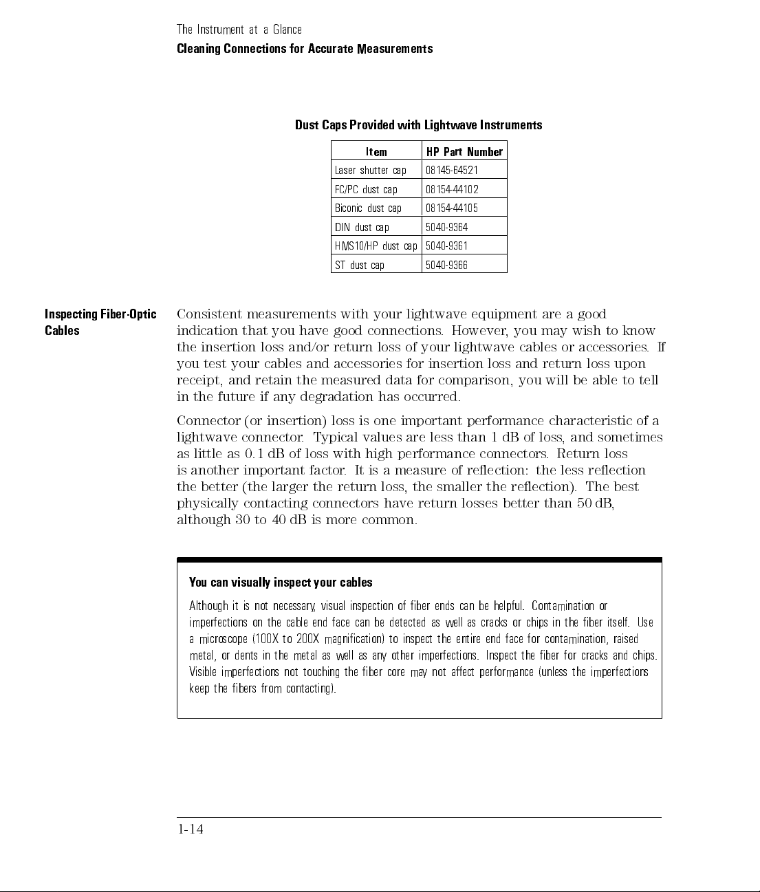
Inspecting
Cables
Fiber-Optic
Consistent
indication
the
insertion
you
test
your
receipt,
in
the
and
future
Connector
lightwave
as
little
as
is
another
the
better
physically
although
measurements
that
you
have
loss
and/or
cables
retain
the
if
any
degradation
(or
insertion)
connector
0.1
dB
.
of
important
(the
larger
contacting
30
to
40
dB
Laser
FC/PC
Biconic
DIN
HMS10/HP
ST
dust
with
good
return
and
accessories
measured
loss
Typical
loss
with
factor
.
the
return
connectors
is more
Item HP
shutter
cap
dust
cap
dust cap
dust
cap
dust
cap
cap
your
connections
loss
of
data
has
occurred.
is
one
important
values
high
performance
It
is
a
measure
loss
,
have
common.
Part
08145-64521
08154-44102
08154-44105
5040-9364
5040-9361
5040-9366
lightwave
.
However
your
lightwave
for
insertion
for
comparison,
are
less
of
the
smaller
return
Number
equipment
,
you
cables
loss
and
you
performance
than
1
dB
connectors
reection:
the
reection).
losses better
are
a
may
or
return
will
characteristic
of
loss,
. Return
the
less reection
than
good
wish
to
accessories
loss
upon
be
able
and
sometimes
loss
The
best
50
dB
,
know
to
tell
of a
.
If
Y
ou
can
visually
Although
imperfections
a
microscope
metal,
or dents
Visible
imperfections
it is
not necessary
on the
(100X
inspect
in the
cable end
to
200X
metal
not
keep the bers from contacting).
1-14
your
, visual
magnication)
as
touching
cables
inspection
face can
well
as
the
be detected
to
an
y
other
ber
core
of
ber
inspect
imperfections.
ma
y
ends
as
the
not
well
aect
can
as
entire
be
helpful.
cracks
or
end
face
Inspect
performance
Contamination
chips
in
for
contamination,
the
ber
(unless
the
ber
for cracks
the
imperfections
or
itself
raised
and chips.
.
Use

To
clean a
Cleaning Connections
non-lensed connector
The
Instrument
for Accurate
at
a
Glance
Measurements
CA
UT
IO
N
Do not
can leave
1.
2.
3.
4.
use any
lmy deposits
Apply
isopropyl
Cotton
end
after
Before
cleaning
connector
Apply
isopropyl
Clean the
paper
back
Some
remove
them.
type of
swabs
cleaning.
.
ber
and
amount
particles
This
foam
on ber
alcohol
can
be
the
ber
alcohol to
end
with
forth
across
of
wiping
when
technique
swab
ends that
to
a
clean
used
as
end,
clean the
a new
the
swab
the
or
mild
application
can
remove
to
clean
optical
can
lint-free
long
as
no cotton
ferrules and
clean lint-free
or
lens
ber
end
several
scrubbing
of
alcohol
or
displace
ber
degrade
cotton swab
bers remain
cotton
paper
.
Move
times
of
the
alone
particles
ends
.
F
oam
performance
or lens
other
parts
swab
the
swab
.
ber
end
will
not
smaller
swabs
.
paper.
on the
of
or
lens
can
help
remove
the
or
than
ber
paper
lens
one
.
micron.
5.
Immediately
lens
6.
Blow
ltered,
the
ber
Nitrogen
paper
across
dry
.
the
dry
,
compressed
end
face
gas
the
ber
connector
.
or
compressed
end
air
end
.
with
face
Aim
dust
a
clean,
from
the
compressed
remover
dry
a
distance
can
,
lint-free
gas
also
of
cotton
6
to
8
at a
shallow angle
be
used.
swab
inches
or
using
to
Do
not
C
A
U
T
I
O
N
particles
shake,
compressed air
7. As soon as the connector is dry
in
the can
tip,
or invert
canister.
into the
compressed air
air.
Refer to
canisters
instructions
,
, connect or cover it for later use
because
provided
this
on
releases
the
.
1-15

The
Instrument
at
a
Glance
Cleaning Connections
To
clean an
for Accurate
adapter
Measurements
1. Apply
2.
3.
4.
C
A
U
T
I
O
N
Do not
particles in
compressed
T
o
isopropyl alcohol
Cotton swabs
cleaning. The
enough to
Although foam
thin, and
adapters greatly
Clean
the
adapter
Dry
the
inside
Blow
through
Nitrogen
shake
gas
,
tip
the
air canister
test
insertion
can be
foam swabs
t into
swabs can
the risk
of the
the
adapter using
or
,
or
invert
can
into
to a
used as
adapters
of
other
outweighs
with
the
foam
adapter with
compressed
compressed
the
air
.
.
loss
clean
foam
swab
long as
listed in
no
this section's
.
leave
lmy
deposits
contamination
the
risk
of
swab
.
a clean,
ltered, dry
dust
remover
air
canisters
Refer
to
instructions
.
cotton
bers
introduction
,
these
buildup
on
contamination
dry
,
foam
, compressed
can also
be used.
,
because
provided
remain
deposits
the
by
swab
inside
foam
.
air.
this
on
after
are
small
are
very
of
swabs
releases
the
.
Use
an
test
insertion
following
HP
71450A
appropriate
equipment:
loss
or
lightwave
.
Examples
71451A
of
optical
source
test
spectrum
and
a
compatible
equipment
analyzers
lightwave
congurations
with
Option
white light source
HP 8702 or 8703 lightwave component analyzer system
HP 83420 lightwave test set with an HP 8510 network analyzer
HP 8153 lightwave multimeter
with a source and power sensor module
1-16
receiver
include
002
to
the
built-in

To
test return
loss
The
Instrument
at
a
Glance
Use an
coupler to
appropriate lightwave
test return
the following
HP
8703 lightwave
HP
8702 analyzer
coupler
HP
8504
precision
HP
8153
lightwave
conjunction
HP
81554SM
loss.
equipment:
component
with
reectometer
multimeter
with
a
lightwave
dual
source and
source,
Examples
the
appropriate
a
lightwave
of
test
analyzer
with
a
source
coupler
HP 81534A
equipment
source
,
and
return loss
receiver
receiver
power
module
,
and
lightwave
congurations
,
and
lightwave
sensor
module
include
in
1-17
 Loading...