


Agilent 83433A
Lightwave Transmitter
User’s Guide

© Copyright
Agilent Technologies 2000
All Rights Reserved. Reproduction, adaptation, or translation without prior written
permission is prohibited,
except as allowed under copyright laws.
Agilent Part No. 83433-90001
Printed in USA
February 2000
Agilent Technologies
Lightwave Division
1400 Fountaingrove Parkway
Santa Rosa, CA 95403-1799,
USA
(707) 577-1400
Notice.
The information contained in
this document is subject to
change without notice. Companies, names, and data used
in examples herein are fictitious unless otherwise noted.
Agilent Technologies makes
no warranty of any kind with
regard to this material, including but not limited to, the
implied warranties of merchantability and fitness for a
particular purpose. Agilent
Technologies shall not be liable for errors contained herein
or for incidental or consequential damages in connection with the furnishing,
performance, or use of this
material.
Restricted Rights Legend.
Use, duplication, or disclosure by the U.S. Government
is subject to restrictions as set
forth in subparagraph (c) (1)
(ii) of the Rights in Technical
Data and Computer Software
clause at DFARS 252.227-7013
for DOD agencies, and subparagraphs (c) (1) and (c) (2)
of the Commercial Computer
Software Restricted Rights
clause at FAR 52.227-19 for
other agencies.
Warranty.
This Agilent Technologies
instrument product is warranted against defects in
material and workmanship for
a period of one year from date
of shipment. During the warranty period, Agilent Technologies will, at its option, either
repair or replace products
which prove to be defective.
For warranty service or repair,
this product must be returned
to a service facility designated by Agilent Technologies. Buyer shall prepay
shipping charges to Agilent
Technologies and Agilent
Technologies shall pay shipping charges to return the
product to Buyer. However,
Buyer shall pay all shipping
charges, duties, and taxes for
products returned to Agilent
Technologies from another
country.
Agilent Technologies warrants that its software and
firmware designated by Agilent Technologies for use with
an instrument will execute its
programming instructions
when properly installed on
that instrument. Agilent Technologies does not warrant that
the operation of the instrument, or software, or firmware
will be uninterrupted or errorfree.
Limitation of Warranty.
The foregoing warranty shall
not apply to defects resulting
from improper or inadequate
maintenance by Buyer, Buyersupplied software or interfacing, unauthorized modification or misuse, operation
outside of the environmental
specifications for the product,
or improper site preparation
or maintenance.
No other warranty is
expressed or implied. Agilent
Technologies specifically disclaims the implied warranties
of merchantability and fitness
for a particular purpose.
Exclusive Remedies.
The remedies provided herein
are buyer's sole and exclusive
remedies. Agilent Technolo-
gies shall not be liable for any
direct, indirect, special, incidental, or consequential damages, whether based on
contract, tort, or any other
legal theory.
Safety Symbols.
CAUTION
The
caution
sign denotes a
hazard. It calls attention to a
procedure which, if not correctly performed or adhered
to, could result in damage to
or destruction of the product.
Do not proceed beyond a caution sign until the indicated
conditions are fully understood and met.
WAR NING
The
warning
sign denotes a
hazard. It calls attention to a
procedure which, if not correctly performed or adhered
to, could result in injury or
loss of life. Do not proceed
beyond a warning sign until
the indicated conditions are
fully understood and met.
The instruction manual symbol. The product is marked with this
warning symbol when
it is necessary for the
user to refer to the
instructions in the
manual.
The laser radiation
symbol. This warning
symbol is marked on
products which have a
laser output.
The AC symbol is used
to indicate the
required nature of the
line module input
power.
The ON symbols are
|
used to mark the positions of the instrument
power line switch.
The OFF symbols
❍
are used to mark the
positions of the instrument power line
switch.
The CE mark is a registered trademark of
the European Community.
The CSA mark is a registered trademark of
the Canadian Standards Association.
The C-Tick mark is a
registered trademark
of the Australian Spectrum Management
Agency.
This text denotes the
ISM1-A
instrument is an
Industrial Scientific
and Medical Group 1
Class A product.
Typographical Conventions.
The following conventions are
used in this book:
Key type
for keys or text
located on the keyboard or
instrument.
Softkey type
for key names that
are displayed on the instrument’s screen.
Display type
for words or
characters displayed on the
computer’s screen or instrument’s display.
User type
for words or charac-
ters that you type or enter.
Emphasis
type for words or
characters that emphasize
some point or that are used as
place holders for text that you
type.
ii

General Safety Considerations
General Safety Considerations
This product has been designed and tested in accordance with IEC Publication 61010-1, Safety Requirements for Electrical Equipment for Measurement,
Control, and Laboratory Use, and has been supplied in a safe condition. The
instruction documentation contains information and warnings that must be
followed by the user to ensure safe operation and to maintain the product in a
safe condition.
WARNING
WARNING
WARNING
WARNING
WARNING
WARNING
If this instrument is not used as specified, the protection provided by
the equipment could be impaired. This instrument must be used in a
normal condition (in which all means for protection are intact) only.
To prevent electrical shock, disconnect the Agilent 83433A from
mains before cleaning. Use a dry cloth or one slightly dampened with
water to clean the external case parts. Do not attempt to clean
internally.
This is a Safety Class 1 product (provided with a protective earthing
ground incorporated in the power cord). The mains plug shall only be
inserted in a socket outlet provided with a protective earth contact.
Any interruption of the protective conductor inside or outside of the
product is likely to make the product dangerous. Intentional
interruption is prohibited.
No operator serviceable parts inside. Refer servicing to qualified
personnel. To prevent electrical shock, do not remove covers.
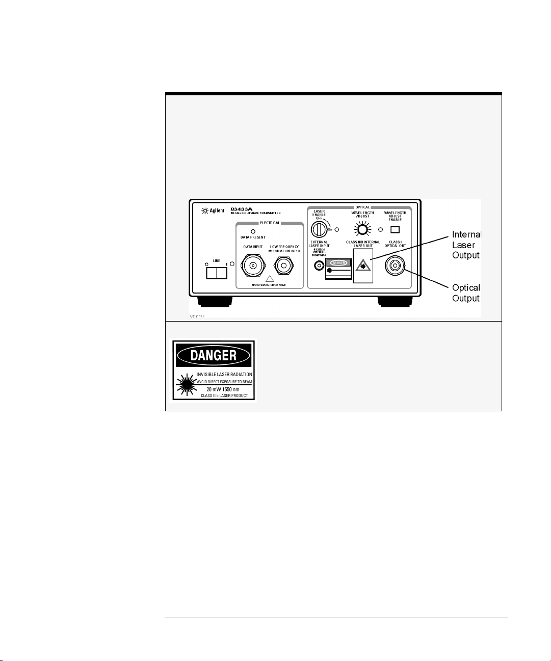
Do not, under any circumstances, look into the optical output or any
fiber/device attached to the output while the laser is in operation.
Do not enable the laser when no fiber or equivalent device is attached
to the OPTICAL OUTPUT connector.
WARNING
For continued protection against fire hazard, replace line fuse only
with same type and ratings (5x20 mm,1.6 A, 250 V time-delay, low
braking capacity fuse). The use of other fuses or materials is
prohibited.
iii

General Safety Considerations
CAUTION
CAUTION
CAUTION
CAUTION
CAUTION
This product is designed for use in Installation Category II and Pollution
Degree 2 per IEC 61010-1 and 664 respectively.
VENTILATION REQUIREMENTS: When installing the product in a cabinet, the
convection into and out of the product must not be restricted. The ambient
temperature (outside the cabinet) must be less than the maximum operating
temperature of the product by 4°C for every 100 watts dissipated in the
cabinet. If the total power dissipated in the cabinet is greater than 800 watts,
then forced convection must be used.
Always use the three-prong ac power cord supplied with this instrument.
Failure to ensure adequate earth grounding by not using this cord may cause
instrument damage.
Do not
connect ac power until you have verified the line voltage is correct as
described in “GENERAL SPECIFICATIONS” on page 4-3. Damage to the
equipment could result.
This instrument has autoranging line voltage input. Be sure the supply voltage
is within the specified range.
Measurement accuracy—it’s up to you!
Fiber-optic connectors are easily damaged when connected to dirty or damaged cables
and accessories. The Agilent 83433A front-panel OPTICAL INPUT connector is no exception. When you use improper cleaning and handling techniques, you risk expensive
instrument repairs, damaged cables, and compromised measurements.
Before you connect any fiber-optic cable to the Agilent 83433A, refer to “Cleaning Con-
nections for Accurate Measurements” on page 3-6.
iv
General Safety Considerations
Laser classification
The Agilent 83433A is classified as an IEC LASER Class 3B according to
IEC 825-1:1999-11, and an FDA LASER class 3B according to 21CFR 1040.10. The total
power of light energy radiated out of the LASER OUT connector is 8.5 to 11 dBm. Opera-
tor precautions are necessary to maintain safety. The Agilent 83433A contains no user
serviceable parts. Removal of covers may result in hazardous radiation exposure.
v
The Agilent 83433A—At a Glance
The Agilent 83433A—At a Glance
The Agilent 83433A lightwave transmitter is based on a lithium niobate modulator driven by an internal CW DFB 1552.52 nm laser. The laser and modulator
are inter-connected externally with a PMF fiber. The modulator can also be
used with an external laser with polarization maintaining fiber such as the Agilent 8164A, with 81680A option 071.
The Agilent 83433A is designed to produce high fidelity, low jitter waveforms
for 2.488 Gb/s STM-16/OC-48, 9.953 Gb/s STM-64/OC-192 and other transmission rates up through 10.7 Gb/s. The Agilent 83433A is intended for BER testing with error performance analyzers such as the Agilent 71612B. The MachZehnder modulator is adjusted for a fixed zero chirp. Its output waveform produces a minimum extinction ratio of 12 dB.
The internal DFB laser can be modulated at frequencies from 15 kHz to
10 MHz to increase linewidth for SBS suppression or channel identification
applications. The internal laser wavelength can be adjusted ±1.25 nm around
the 1552.52 center wavelength.
The Agilent 83433A can be combined with the Agilent 83434A 10 Gb/s lightwave receiver to create a complete optical link for system or fiber testing, or to
form a basis for substitution testing of commercial transmitters and receivers.
vi

Contents
The Agilent 83433A—At a Glance vi
1 Getting Started
2 Using the Agilent 83433A
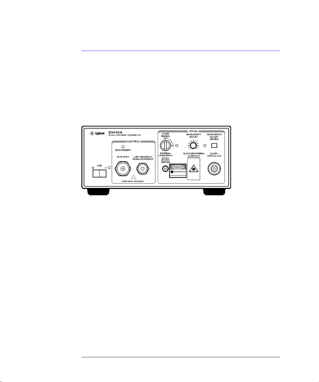
Front-Panel Features 2-2
Rear-Panel Features 2-4
Using a Laser Source 2-5
Performing a Quick Confidence Check 2-6
Connecting the Agilent 83433A to a Bit-Error-Ratio Test Set 2-9
Connecting the Agilent 83433A to an Oscilloscope 2-11
3 Reference
Options 3-2
Replacement Parts 3-3
Front-Panel Fiber-Optic Adapters 3-4
Power Cords 3-5
Cleaning Connections for Accurate Measurements 3-6
Returning the Instrument for Service 3-17
Agilent Technologies Service Offices 3-20
4 Specifications and Regulatory Information
Agilent 83433A Specifications and Characteristics 4-3
Regulatory Information 4-6
Contents-1


1
Step 1. Inspect the Shipment 1-3
Step 2. Check the Fuse 1-5
Step 3. Connect the Line-Power Cable 1-6
Step 4. Turn on the Agilent 83433A 1-8
Step 5. Avoid costly repairs 1-9
Step 6. Learn more about our products 1-10
Getting Started

Getting Started
Setting Up the Agilent 83433A
Setting Up the Agilent 83433A
The instructions in this chapter show you how to install your lightwave transmitter. After you’ve completed this chapter, continue with Chapter 2, “Using
the Agilent 83433A”. Refer to Chapter 3, “Reference” for the following addi-
tional information:
• Tips on avoiding
techniques.
• Lists of available accessories and power cords.
• Instructions on returning your instrument to Agilent Technologies for service.
• Agilent Technologies Sales and Service Offices.
Chapter 4, “Specifications and Regulatory Information” contains information
on operating conditions, such as temperature.
costly
repairs by proper optical connection cleaning
1-2

Step 1. Inspect the Shipment
Getting Started
Setting Up the Agilent 83433A
NOTE
The Agilent 83433A is supplied with an optical jumper cable. To avoid costly
replacement, do not misplace this cable.
❒
Inspect the shipping container for damage.
❒
Inspect the instrument.
❒
Verify that you received the options and accessories you ordered.
Keep the shipping container and cushioning material until you have inspected
the contents of the shipment for completeness and have checked the lightwave transmitter mechanically and electrically.
The lightwave transmitter is packed within a carton. Refer to “Returning the
Instrument for Service” on page 3-16, for the description and part numbers of
the packaging materials. Refer to “Options” on page 3-2, for the accessories
shipped with the lightwave transmitter.
If the shipping materials are in good condition, retain them for possible future
use. You may wish to ship the lightwave transmitter to another location or
return it to Agilent Technologies for service. Refer to “Returning the Instru-
ment for Service” on page 3-16.
1-3

Getting Started
Setting Up the Agilent 83433A
If anything is missing or defective, or if the lightwave transmitter does not
pass the verification test, contact your nearest Agilent Technologies Sales
Office. If the shipment was damaged, contact the carrier, then contact the
nearest Agilent Technologies Sales Office. Keep the shipping materials for the
carrier’s inspection. The Agilent Sales Office will arrange for repair or replacement at Agilent Technologies’ option without waiting for claim settlement.
Serial numbers
Agilent Technologies makes frequent improvements to its products to
enhance their performance, usability, or reliability, and to control costs. Agilent service personnel have access to complete records of design changes to
each type of equipment, based on the equipment’s serial number. Whenever
you contact Agilent about your lightwave transmitter, have the complete serial
number available to ensure obtaining the most complete and accurate information possible.
A serial-number label is attached to the rear of the lightwave transmitter. It
contains the serial number and the options installed in the lightwave transmitter. Whenever you specify the serial number or refer to it in obtaining information about your lightwave transmitter, be sure to use the complete number.
1-4

Step 2. Check the Fuse
Getting Started
Setting Up the Agilent 83433A
WARNING
1
Locate the line-input connector on the instrument’s rear panel.
2
Disconnect the line-power cable if it is connected.
3
Use a small flat-blade screwdriver to pry open the fuse holder door.
4
The fuse is housed in a small container. Insert the tip of a screwdriver on the
side of the container and gently pull outward to remove the container. A spare
fuse is stored below the line fuse.
For continued protection against fire hazard, replace line fuse only
with same type and ratings (5×20 mm,1.6 A, 250 V time-delay, low
breaking capacity fuse). The use of other fuses or materials is
prohibited.
1-5
Getting Started
Setting Up the Agilent 83433A
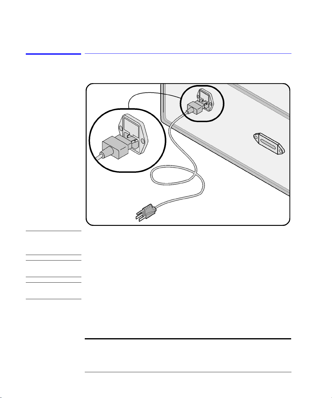
Step 3. Connect the Line-Power Cable
CAUTION
CAUTION
CAUTION
Always use the three-prong AC power cord supplied with this instrument.
Failure to ensure adequate earth grounding by not using this cord may cause
instrument damage.
not
Do
connect ac power until you have verified the line voltage is correct as
described in the following paragraphs. Damage to the equipment could result.
This instrument has autoranging line voltage input. Be sure the supply voltage
is within the specified range.
1
Verify that the line power meets the requirements shown in the following table.
Line Power Requirements
Power 115 VAC: 50 WATTS MAX
230 VAC: 50 WATTS MAX
1-6

Getting Started
Setting Up the Agilent 83433A
Line Power Requirements
Voltage nominal: 115 VAC range: 90–132 V
nominal: 230 VAC range: 98–254 V
Frequency nominal: 50 Hz/60 Hz range: 47–63 Hz
2
Connect the line-power cord to the rear-panel connector of the instrument.
3
Connect the other end of the line-power cord to the power receptacle.
Various power cables are available to connect the Agilent 83433A to ac power
outlets unique to specific geographic areas. The cable appropriate for the area
to which the Agilent 83433A is originally shipped is included with the unit. You
can order additional ac power cables for use in different geographic areas.
Refer to “Power Cords” on page 3-5.
1-7

Getting Started
Setting Up the Agilent 83433A
Step 4. Turn on the Agilent 83433A
NOTE
• Press the front-panel
LINE
key. All front-panel LED’s will light momentarily. The
line power indicator will remain lit.
The front panel LINE switch disconnects the mains circuit from the mains supply after
the EMC filters and before other parts of the instrument.
If the Agilent 83433A fails to turn on properly, consider the following possibilities:
❒
Is the line fuse good?
❒
Does the line socket have power?
❒
Is it plugged into the proper ac power source?
If the instrument still fails, return it to Agilent Technologies for repair. Refer to
“Returning the Instrument for Service” on page 3-17.
1-8
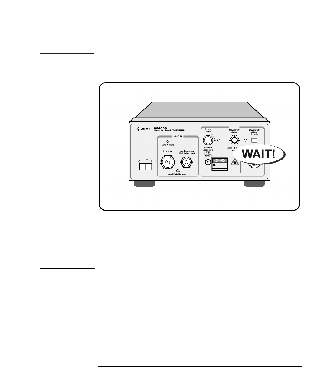
Step 5. Avoid costly repairs
Getting Started
Setting Up the Agilent 83433A
CAUTION
CAUTION
Fiber-optic connectors are easily damaged when connected to dirty or
damaged cables and accessories. The front-panel connectors of the
Agilent 83433A are no exception. When you use improper cleaning and
handling techniques, you risk expensive instrument repairs, damaged cables,
and compromised measurements. Before you connect any fiber-optic cable to
the Agilent 83433A, refer to “Cleaning Connections for Accurate
Measurements” on page 3-6.
For proper operation without an external laser, connect the supplied optical
jumper cable between the EXTERNAL LASER INPUT and the CLASS IIIB
INTERNAL LASER OUT. Be sure to position the LASER ENABLE key in the off
position before making any connection. Agilent recommends the use of Panda
PMF fiber with the EXTERNAL LASER INPUT.
1-9
Getting Started
Setting Up the Agilent 83433A
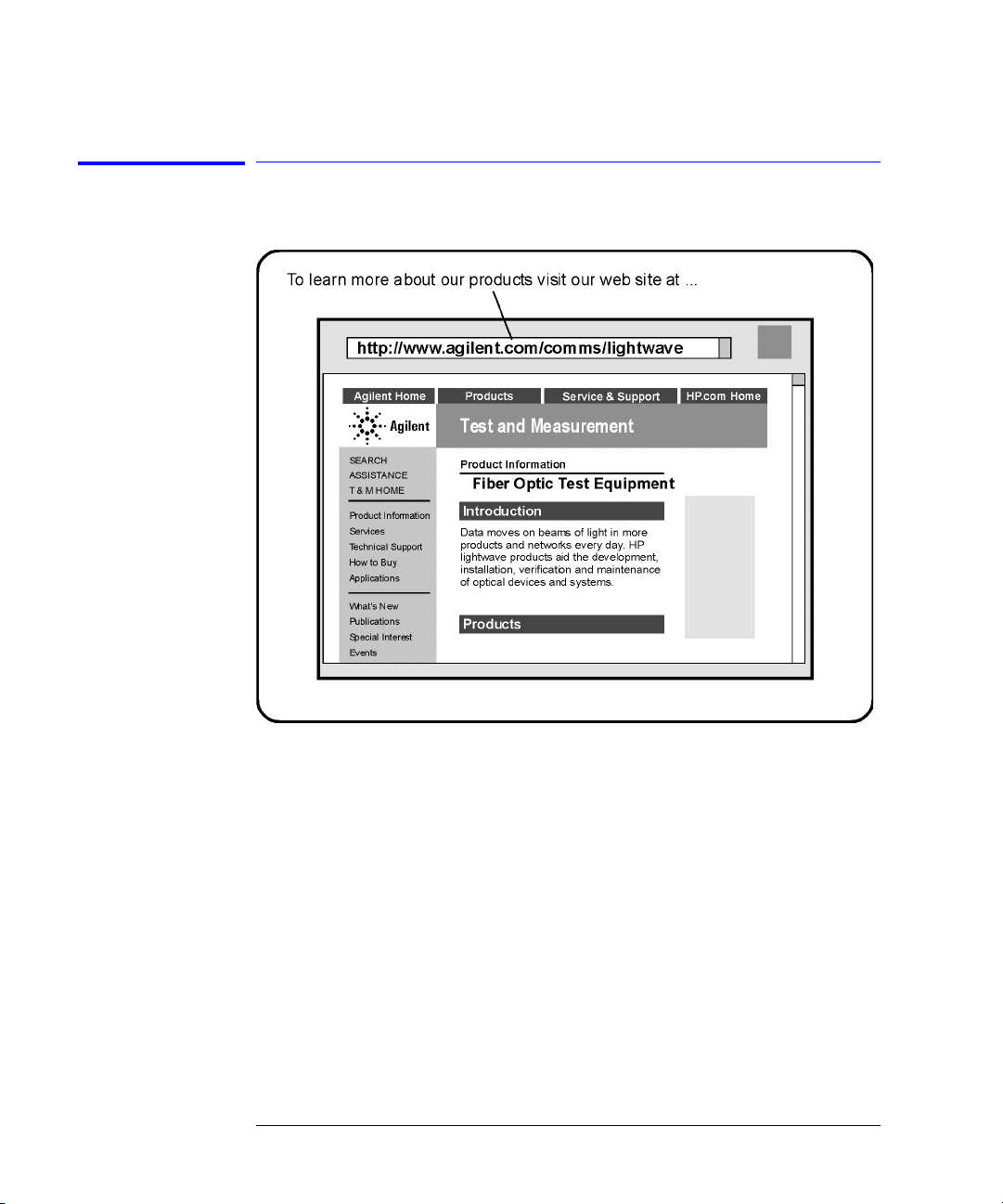
Step 6. Learn more about our products
To learn more about this or any Agilent Technologies product, visit our website at http://www.agilent.com.
To learn more about Fiber Optic Test Equipment, go to the Agilent Technologies home page listed above, and follow this path:
1
Click Products.
2
Click Test and Measurement.
3
Under Products, click Fiber Optic Test Equipment.
This path will take you to the Fiber Optic Test Equipment page.
Or you can enter the URL for this page directly:
http://www.tm.agilent.com/tmo/Products/English/FiberOpticTestEquipment.html
1-10
 Loading...