

Operating and Programming Manual
HP 81534A Return Loss Module
SERIAL NUMBERS
This manual applies to all instruments.
ABCDE
HP Part No. 81534-90012
Printed in Germany
Second Edition
E0796

Notices
This document contains proprietary
information which is protected by
copyright. All rights are reserved.
No part of this document may be
photocopied, reproduced, or
translated to another language
without the prior written consent of
Hewlett-Packard GmbH.
c
Copyright 1992 by:
Hewlett-Packard GmbH
Herrenberger Str. 130
7030 Boeblingen
Federal Republic of Germany
Subject Matter
The information in this document is
subject to change without notice.
Hewlett-Packard makes no warranty
of any kind with regard to this
printed material, including, but not
limited to, the implied warranties of
merchantability and tness for a
particular purpose.
Hewlett-Packard shall not be liable
for errors contained herein or for
incidental or consequential damages
in connection with the furnishing,
performance, or use of this material.
Printing History
New editions are complete revisions
of the manual. Update packages,
contain additional and replacement
information to be incorporated into
the manual by the customer. The
date on the title page only changes
when a new manual is published.
When an edition is reprinted, all the
prior updates to the edition are
incorporated.
Warranty
This Hewlett-Packard instrument
product is warranted against defects
in material and workmanship for a
period of one year from date of
shipment. During the warranty
period, HP will, at its option, either
repair or replace products which
prove to be defective.
For warranty service or repair, this
product must be returned to a service
facility designated by HP. Buyer shall
prepay shipping charges to HP and
HP shall pay shipping charges to
return the product to Buyer.
However, Buyer shall pay all shipping
charges, duties, and taxes for
products returned to HP from
another country.
HP warrants that its software and
rmware designated by HP for use
with an instrument will execute its
programming instructions when
properly installed on that instrument.
HP does not warrant that the
operation of the instrument,
software, or rmware will be
uninterrupted or error free.
Limitation of Warranty
The foregoing warranty shall not
apply to defects resulting from
improper or inadequate maintenance
by Buyer, Buyer-supplied software or
interfacing, unauthorized
modication or misuse, operation
outside of the environmental
specications for the product, or
improper site preparation or
maintenance.
No other warranty is expressed or
implied. Hewlett-Packard specically
Exclusive Remedies
The remedies provided herein are
Buyer's sole and exclusive remedies.
Hewlett-Packard shall not be liable
for any direct, indirect, special,
incidental, or consequential
damages whether based on contract,
tort, or any other legal theory.
Assistance
Product maintenance agreements
and other customer assistance
agreements are available for
Hewlett-Packard products.For any
assistance contact your nearest
Hewlett-Packard Sales and Service
Oce.Addresses are provided at
the back of this manual.
Certication
Hewlett-Packard Company certies
that this product met its published
specications at the time of
shipment from the factory.
Hewlett-Packard further certies
that its calibration measurements
are traceable to the United States
National Institute of Standards and
Technology, NIST (formerly the
United States National Bureau of
Standards, NBS) to the extent
allowed by the Institute's calibration
facility, and to the calibration
facilities of other International
Standards Organization members.
disclaims the implied warranties of
Merchantability and Fitness for a
Particular Purpose.
Control Serial Number: Edition 1 applies directly to all standard (connector output) instruments.
Edition 2 applies to all instruments (connector and pigtail outputs).
Edition 1 : 1st June 1991 : 81534-90011 : E0691
Edition 2 : 1st November 1991 : 81534-90012 : E1191 ; 1st December 1992 : 81534-90012 : E1292 ; 1st
February 1994 : 81534-90012 : E0294 ; 1st February 1996 : 81534-90012 : E0296 ; 1st July 1996 : 81534-90012
: E0796

Safety Considerations
Before operation, review the instrument and manual, including the red safety
page, for safety markings and instructions
.You must follow these to ensure safe
operation and to maintain the instrument in safe condition.
Initial Inspection
Inspect the shipping container for damage. If there is damage to the container
or cushioning, keep it until you have checked the contents of the shipment for
completeness and veried the module both mechanically and electrically.
The Performance Tests give procedures for checking the operation of the
module. If the contents are incomplete, mechanical damage or defect is
apparent, or if a module does not pass the operator's checks, notify the nearest
Hewlett-Packard oce.
Warning
To avoid hazardous electrical shock, do not perform
electrical tests when there are signs of shipping damage to
any portion of the outer enclosure (covers, panels, etc.).
Power Requirements
The HP 81534A operates when installed into the HP 8153A Optical Multimeter
mainframe.
Operating Environment
The HP 8153A safety information summarizes the HP 81534A operating
environment ranges. In order for the HP 81534A to meet specications, the
operating environment must be within the limits specied in this section.
Storage and Shipment
The module can be stored or shipped at temperatures between040
C and
+70C. Protect the module from temperature extremes that may cause
condensation within it.
v

Contents
2. The HP 81534A in Measure Mode
How to Make Return Loss Measurements with the HP 81534A .. 2-1
Setting up to Make a Return Loss Measurement ........ 2-2
Making Calibration Measurements ...... ...... .. 2-5
Measuring the Reection Reference . . . . . . . . . . . . . 2-5
Measuring the Termination Parameter . . . . . . . . . . . . 2-6
Measuring the Return Loss . . . . . . . . . . . . . . . . . .
The HP 81534A in Measure Mode - Some Exceptions . . . . . . .
A Background to Return Loss Measurements with the HP 81534A
Taking Calibration Measurements . . . . . . . . . . . . . . .
Measuring the Reected Power from a Component with Known
Reection Factor . . . . . . . . . . . . . . . . . . . . 2-9
Measuring the Power when there are No Reections . . . . . 2-10
Using our Measured Powers to get an Equation in Known Terms 2-10
Measuring the Reections from the DUT ........... 2-11
Using our Measurements to Calculate the Return Loss .. .. 2-11
Summary .......................... 2-12
3. The HP 81534A in Menu Mode
8. The HP 81534A HP-IB Commands
ABORt Commands . . . . . . . . . . . . . . . . . . . . . . . 8-1
Specifying the Channel . . . . . . . . . . . . . . . . . . . . 8-1
ABORt ........................... 8-2
FETCh Commands . . . . . . . . . . . . . . . . . . . . . . . 8-3
Specifying the Channel . . . . . . . . . . . . . . . . . . . . 8-3
FETCh[:SCALar]:POWer[:DC] . . . . . . . . . . . . . . . . . 8-3
INITiate Commands .. ...... ...... ..... ... 8-5
Specifying the Channel . . . . . . . . . . . . . . . . . . . . 8-5
INITiate:CONTinuous .................... 8-5
INITiate:CONTinuous? .................... 8-6
INITiate[:IMMediate] . . . . . . . . . . . . . . . . . . . . . 8-6
2-7
2-8
2-8
2-9
Contents-1

READ Commands ....................... 8-7
Specifying the Channel . . . . . . . . . . . . . . . . . . . . 8-7
READ[:SCALar]:POWer[:DC] ................. 8-7
SENSe Commands . . . . . . . . . . . . . . . . . . . . . . . 8-9
Specifying the Channel . . . . . . . . . . . . . . . . . . . . 8-9
SENSe:CORRection:COLLect:ZERO ........ ..... . 8-10
SENSe:CORRection:COLLect:ZERO? . . . . . . . . . . . . . . 8-10
SENSe:CORRection[:LOSS[:INPut[:MAGNitude]]] . . . . . . . . 8-11
SENSe:CORRection[:LOSS[:INPut[:MAGNitude]]]? .... ... 8-11
SENSe:POWer:ATIME .................... 8-12
SENSe:POWer:ATIME? . . . . . . . . . . . . . . . . . . . . 8-12
SENSe:POWer:RANGe:AUTO? .. ...... ...... .. 8-13
SENSe:POWer:RANGe[:UPPER]? ............... 8-13
SENSe:POWer:REFerence? .................. 8-14
SENSe:POWer:REFerence:STATe ............... 8-15
SENSe:POWer:WAVElength . . . . . . . . . . . . . . . . . . 8-15
SENSe:POWer:WAVElength? ................. 8-16
B. HP 81534A Accessories
C. HP 81534A Specications
Denition of Terms ...................... C-1
Performance Specications . . . . . . . . . . . . . . . . . . .
D. HP 81534A Performance Test
Equipment Required . . . . . . . . . . . . . . . . . . . . . D-1
Test Record .......................... D-2
Test Failure .......................... D-3
Instrument Specication .................... D-3
Performance Test (Standard Module) .............. D-3
I. Dynamic Range Test / Noise Level ............. D-4
II. Relative Uncertainty Test ...... ...... ..... D-7
Taking Attenuator Reference . . . . . . . . . . . . . . . . D-7
III Absolute Uncertainty ................... D-11
I. Dynamic Range /Noise Level ............... D-14
II. Relative Uncertainty .... ...... ..... .. D-14
III. Absolute Uncertainty . . . . . . . . . . . . . . . . . . D-16
C-2
Contents-2
D.1. Calibrate a reector as reference
D.2. Calibrate Cleaved Fiber End As Reference
E. Cleaning Procedures
Cleaning Materials . . . . . . . . . . . . . . . . . . . . . . . E-1
Cleaning Fiber/Front-Panel Connectors .. ...... ..... E-2
Cleaning Connector Interfaces .. ...... ...... ... E-2
Cleaning Connector Bushings . . . . . . . . . . . . . . . . . . E-3
Cleaning Detector Windows .................. E-3
Cleaning Lens Adapters .......... ...... .... E-3
Cleaning Detector Lens Interfaces .... ...... ..... E-4
How to clean instruments with a recessed lens interface . . . . E-4
Light dirt ...... ...... ...... ..... .. E-4
Heavy dirt ........................ E-4
Contents-3

Figures
2-1. The Contents of the HP 81534A Module (Standard Version) . . . 2-1
2-2. Set Up for Return Loss Measurements . . . . . . . . . . . . . 2-3
2-3. HP 81534A: Calibrating for Return Loss Measurements:
procedure as described in steps 1-14 . . . . . . . . . . . . 2-4
2-4. Measuring the Reection Reference . . . . . . . . . . . . . . 2-5
2-5. Measuring the Reection Reference . . . . . . . . . . . . . .
2-6. Measuring the Termination Parameter . . . . . . . . . . . . . 2-6
2-7. Measuring the Termination Parameter . . . . . . . . . . . . . 2-7
2-8. Measuring the Return Loss of the DUT (in this example: a
Connector Pair) .....................
2-9. Return Loss Equipment ................... 2-9
2-10. Measuring the Power from a Component with Known Reection
Factor . . . . . . . . . . . . . . . . . . . . . . . . . . 2-9
2-11. Measuring the Power with the Connector Terminated ..... 2-10
2-12. Measuring the Reections from the Device Under Test ..... 2-11
D-1. Dynamic Range Test Setup .......... ...... .. D-5
D-2. Attenuator reference ...... ...... ...... .. D-7
D-3. Relative Uncertainty . . . . . . . . . . . . . . . . . . . . . D-9
D.1-1. Setting reference reected power . . . . . . . . . . . . . . . D.1-2
D.1-2. Getting R parameter for 100% reected power. .. ...... D.1-3
D.1-3. Setting input reference power ................ D.1-4
D.1-4. Setting T parameter, Measuring
Reector
......................... D.1-5
D.1-5. Setting T parameter, Measuring
Open Connector as Reference
Your
Reference Reector . . . . D.1-6
2-5
2-7
Contents-4
Tables
8-1. ABORt Command Summary .... ...... ...... . 8-1
8-2. FETCh Command Summary ................. 8-3
8-3. INITiate Command Summary . . . . . . . . . . . . . . . . . 8-5
8-4. READ Command Summary . . . . . . . . . . . . . . . . . . 8-7
8-5.
SENSe
Command Summary . . . . . . . . . . . . . . . . . . 8-9
Contents-5

2
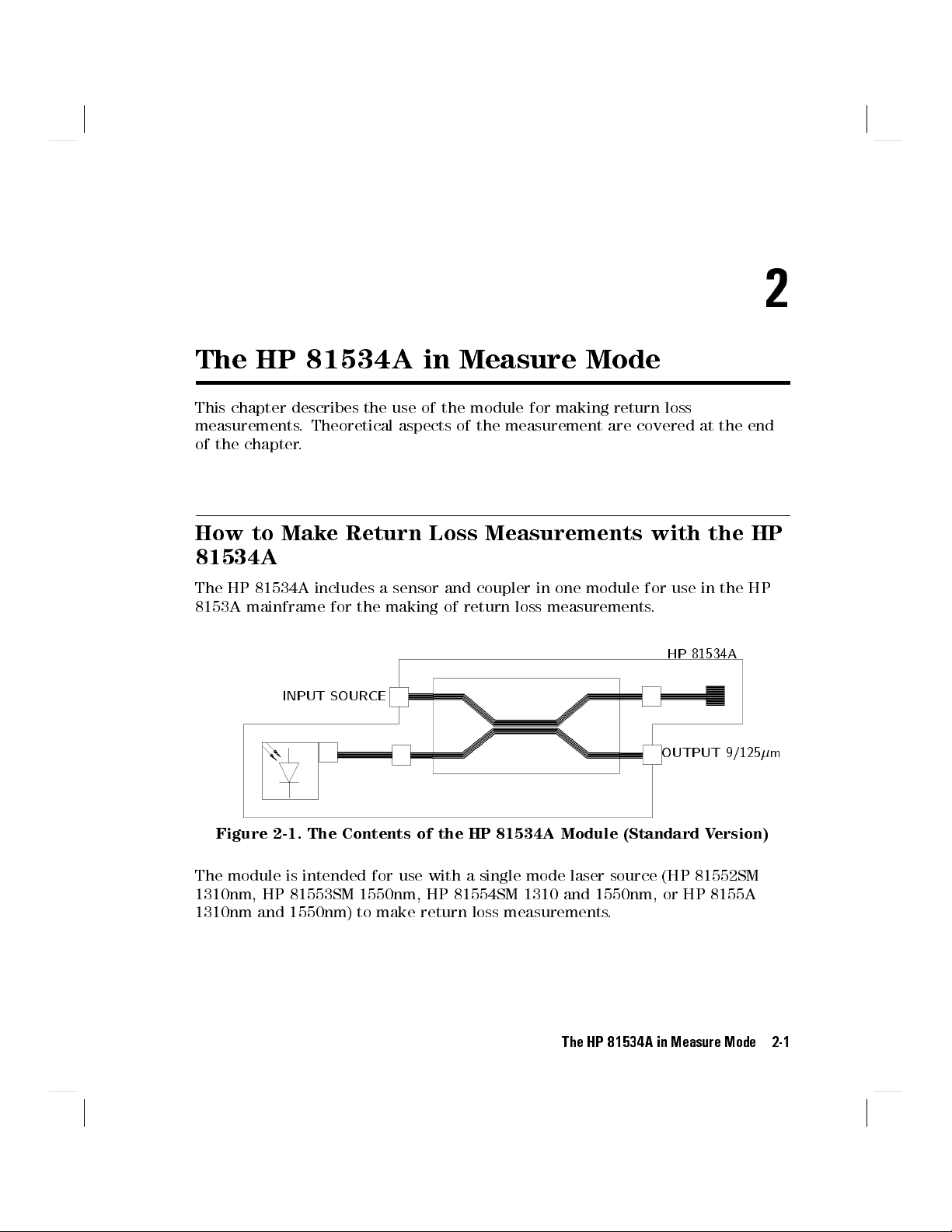
The HP 81534A in Measure Mode
This chapter describes the use of the module for making return loss
measurements. Theoretical aspects of the measurement are covered at the end
of the chapter.
How to Make Return Loss Measurements with the HP
81534A
The HP 81534A includes a sensor and coupler in one module for use in the HP
8153A mainframe for the making of return loss measurements.
HP 81534A
INPUT SOURCE
OUTPUT 9/125m
Figure 2-1. The Contents of the HP 81534A Module (Standard Version)
The module is intended for use with a single mode laser source (HP 81552SM
1310nm, HP 81553SM 1550nm, HP 81554SM 1310 and 1550nm, or HP 8155A
1310nm and 1550nm) to make return loss measurements.
The HP 81534A in Measure Mode 2-1

Setting up to Make a Return Loss Measurement
The return loss setup described here uses a HP 81553SM source, inserted as a
second module in the same mainframe as the return loss module
.
Note
This description is for the standard HP 81534A Return Loss
Module, not for the pigtail version.
Notes are given where the procedure for the pigtail version may
be signicantly dierent.
It is recommended that you attach a patchcord to the return loss module
output.
Caution
HP supplies patchcords with a Diamond HMS-10/HP/HRL
high return loss connector on one end. These patchcords are
necessary so that the connector at the output is not damaged.
The the full range of patchcords available are described in
Appendix B.
Because of the high return loss connector used and a length of ber greater
than the coherence length of the laser source, the patchcord reduces the
disturbance of the source due to reections.
The setup described uses a ber with Diamond HMS-10/HP/HRL and Diamond
HMS-10/HP connectors throughout.
Opt.001
If you are using the HP 81534A Option 001 it is strongly
recommended that you attach a connector or a working ber to
the end of the pigtail so that you can avoid cutting the pigtail
as much as possible. (The replacement of the pigtail ber is not
covered by the warranty for the instrument.)
1. Making sure to clean all the connectors, set up the instrument as shown in
the gure. Connect the source to the HP 81534A Input. Attach the high
return loss connector of the patchcord to the Output. The high return loss
connector on these cables is the connector with the orange sleeve.For best
results and higher repeatability, x the cables.
2-2 The HP 81534A in Measure Mode
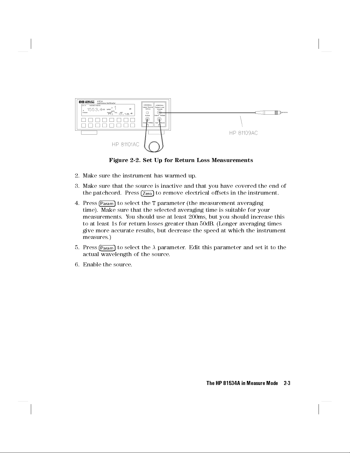
Figure 2-2. Set Up for Return Loss Measurements
2. Make sure the instrument has warmed up.
3. Make sure that the source is inactive and that you have covered the end of
5
the patchcord. Press
5
4. Press
4
Param
time). Make sure that the selected averaging time is suitable for your
measurements.You should use at least 200ms, but you should increase this
to at least 1s for return losses greater than 50dB. (Longer averaging times
give more accurate results, but decrease the speed at which the instrument
measures.)
to select theTparameter (the measurement averaging
to remove electrical osets in the instrument.
4
Zero
5. Press
6. Enable the source.
4
5
Param
actual wavelength of the source.
to select theparameter. Edit this parameter and set it to the
The HP 81534A in Measure Mode 2-3

Figure 2-3.
HP 81534A: Calibrating for Return Loss Measurements: procedure as
described in steps 1-14
2-4 The HP 81534A in Measure Mode
Making Calibration Measurements
Whenever the HP 81534A Return Loss Module is in the HP 8153A mainframe,
the result eld shows return loss
most recently measured, where these are available, or default values.
If you are unsure of one or both of the calibration values you are using, make
the appropriate calibration measurements again. If you have changed your
measurement setup,
Measuring the Reection Reference
5
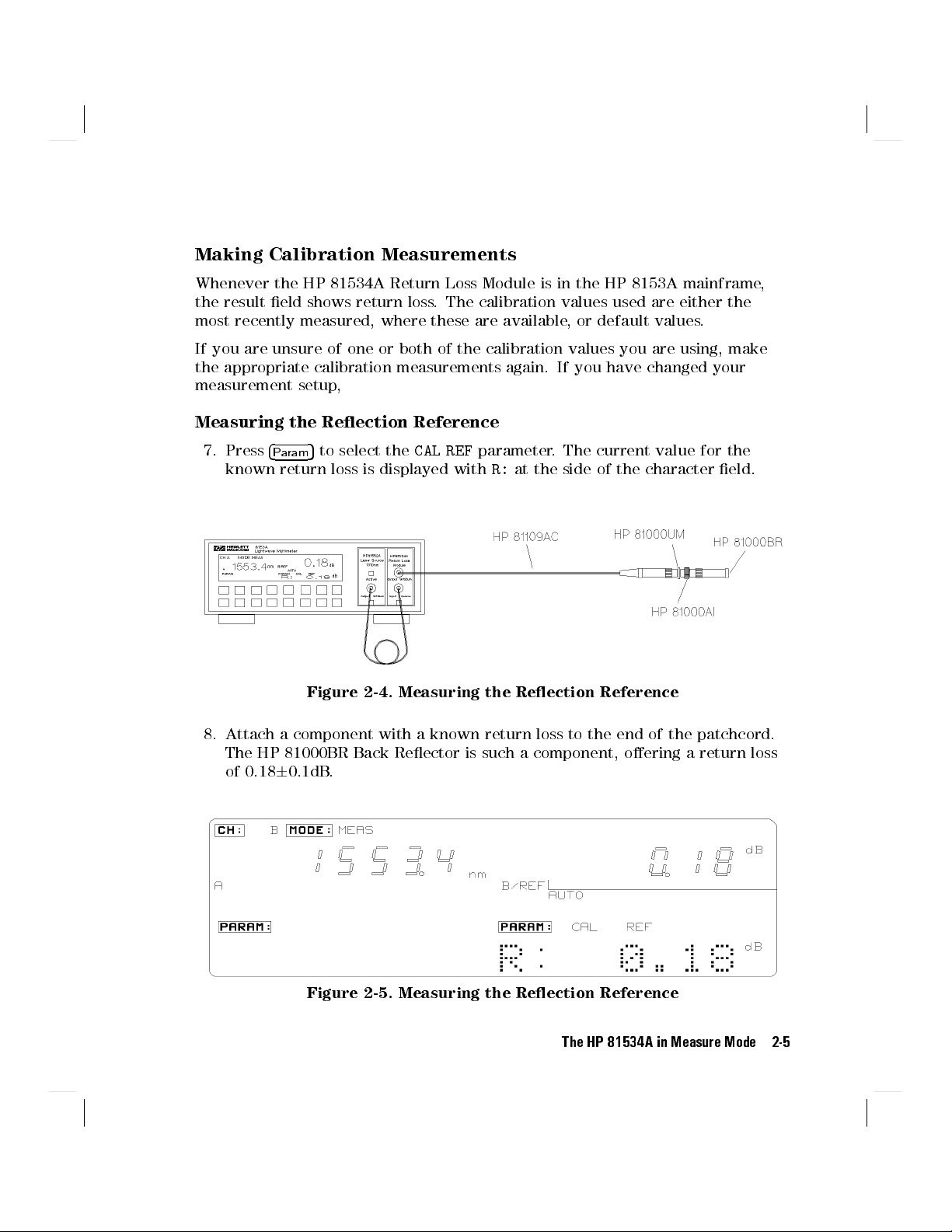
7. Press
4
Param
known return loss is displayed withR:at the side of the character eld.
to select the
Figure 2-4. Measuring the Reection Reference
. The calibration values used are either the
CAL REF
parameter. The current value for the
8. Attach a component with a known return loss to the end of the patchcord.
The HP 81000BR Back Reector is such a component, oering a return loss
of 0.1860.1dB.
Figure 2-5. Measuring the Reection Reference
The HP 81534A in Measure Mode 2-5
9. Make sure that the value displayed forR:is correct. SetR:to the value of
the return loss of the reference reection you are using. For example, if you
are using the HP 81000BR reference reector, setR:0.18dB. If not, edit the
parameter so that it has the correct value.
Opt.001
10. Press
If you are using a cleaved ber end as your reference
reection reference is approximately 14.6dB
5
4
Disp!Ref
. The instrument measures the power reected by the
.
component. The read value should now be the same as the value entered
forR:.
Note
This value may not be the same the rst time you take this
reference after powering the instrument on.
Measuring the Termination Parameter
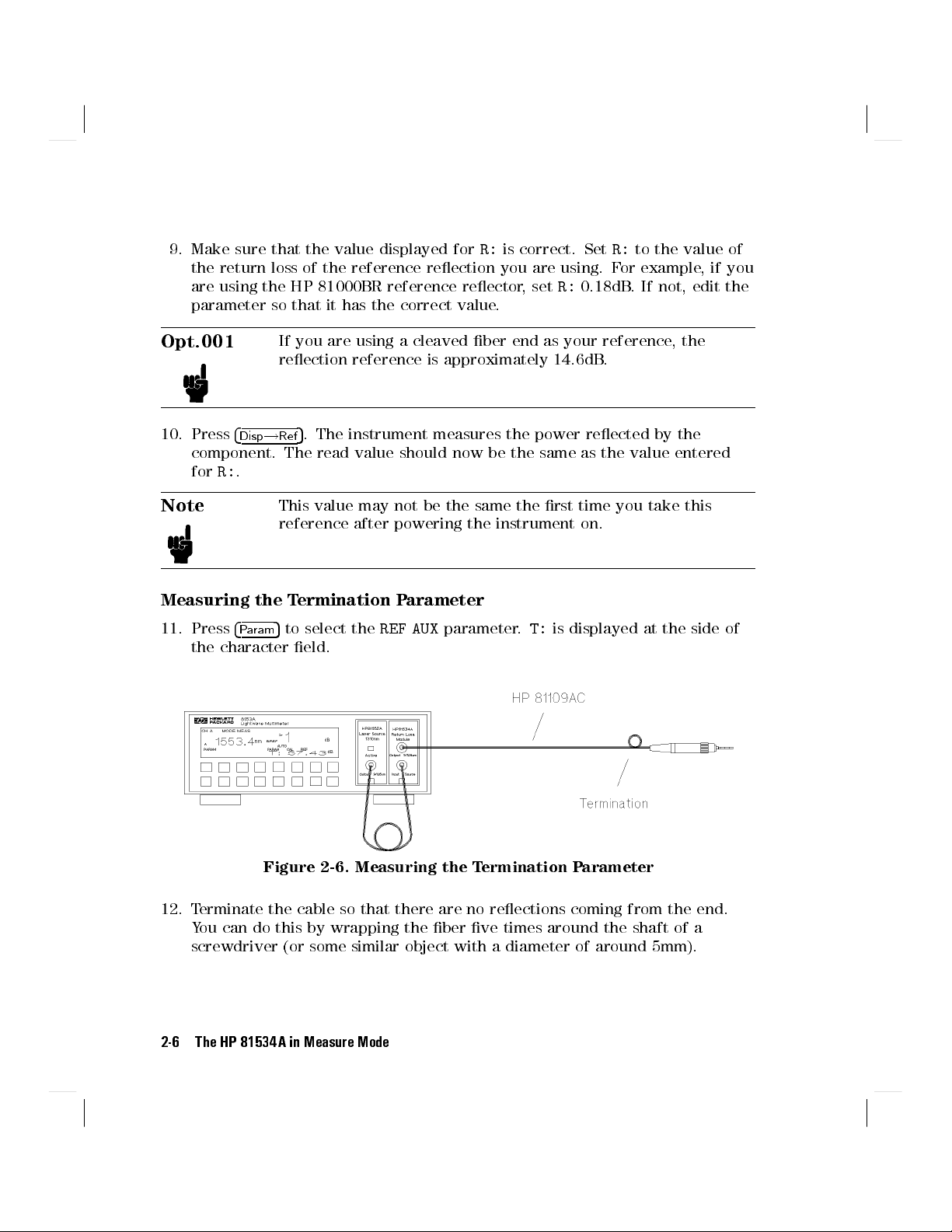
11. Press
4
Param
to select the
REF AUX
parameter.T:is displayed at the side of
5
the character eld.
, the
Figure 2-6. Measuring the Termination Parameter
12. Terminate the cable so that there are no reections coming from the end.
You can do this by wrapping the ber ve times around the shaft of a
screwdriver (or some similar object with a diameter of around 5mm).
2-6 The HP 81534A in Measure Mode
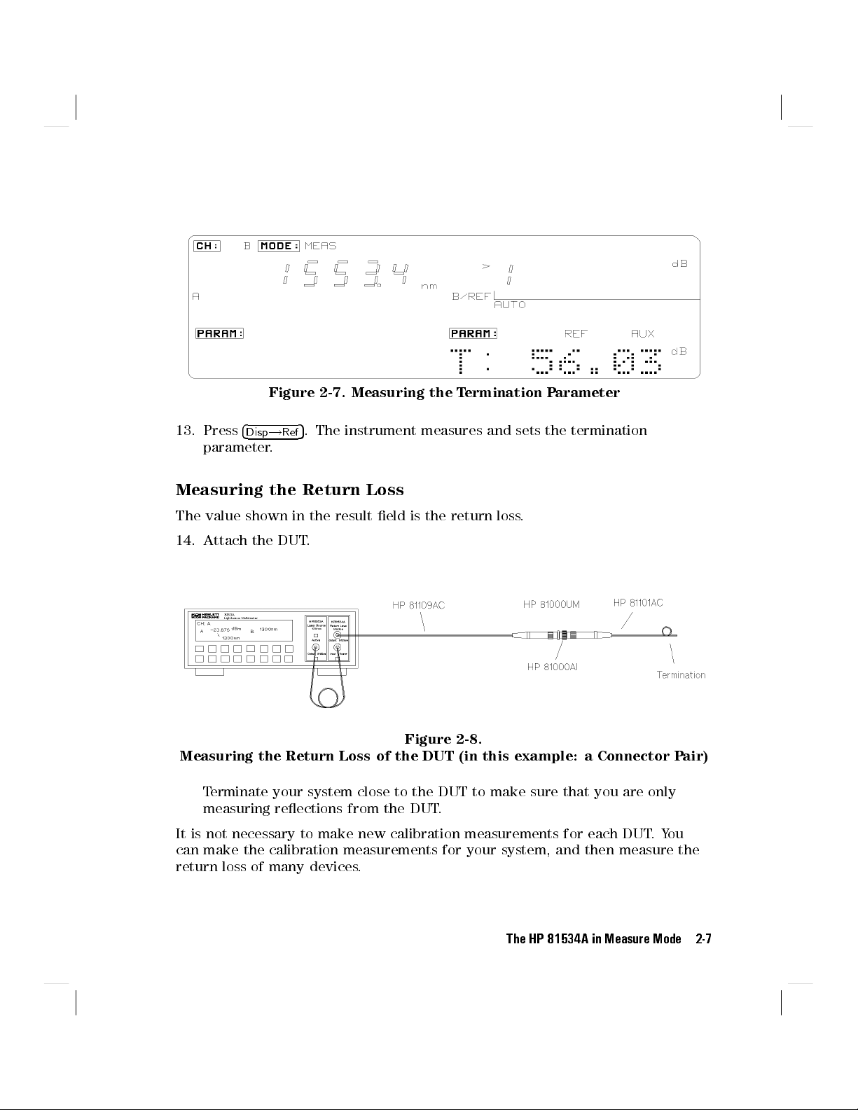
Figure 2-7. Measuring the Termination Parameter
5
13. Press
Measuring the Return Loss
The value shown in the result eld is the return loss.
14. Attach the DUT.
Measuring the Return Loss of the DUT (in this example: a Connector Pair)
4
Disp!Ref
parameter.
Terminate your system close to the DUT to make sure that you are only
measuring reections from the DUT.
. The instrument measures and sets the termination
Figure 2-8.
It is not necessary to make new calibration measurements for each DUT.You
can make the calibration measurements for your system, and then measure the
return loss of many devices.
The HP 81534A in Measure Mode 2-7

The HP 81534A in Measure Mode - Some Exceptions
The HP 81534A acts like any other sensor module when operating in measure
mode with two exceptions.
5
5
The units are xed at dB
and
.
4
dB
Autoranging cannot be disabled.
4
dBm/W
4
Auto
do not have any eect.
5
, and
5,4
Up
4
Down
5
display the selected
range while you are pressing them, but otherwise they have no eect.
A Background to Return Loss Measurements with the
HP 81534A
When light is incident on an optical component, most of it passes through, or
into, the component, some light is absorbed, and some is reected. In many
applications the reections are unwanted, because they can aect the emission
characteristics of any laser in the system. In such applications it is important to
have measurements of the reections for the components in the system.
The reection factor for a component is a measure of how much light the
component reects. It is the ratio of the power reected by the device to
power incident on the device. More normally we talk about the return loss of a
component. The return loss is a value in dB, given by the formula:
Return Loss[dB]=0
10 log(
Reection Factor)[dB
]
or
Return Loss[dB]=0
10 log(
Reected Power
Incident Power
)[dB]
Return loss can be measured in several ways. A description of the method used
by the HP 81534A follows.You can successfully make return loss measurements
with the return loss module without reading this description.
The method used requires the following equipment:
laser source with a stable output,
a power-sensor, and
a coupler.
These are connected as shown in the following gure.
2-8 The HP 81534A in Measure Mode

Source
HP 81534A
A
Coupler
C
Reection-free
Termination
B
D
DUT
Sensor
Figure 2-9. Return Loss Equipment
The description starts with measuring the reection factor. When we have got
this gure, we can convert it easily to the return loss
.
Taking Calibration Measurements
Before measuring the reection factor of a device under test (DUT), take some
calibration measurements. These eliminate wavelength dependencies, coupler
directivity, insertion losses, backscattering and other non-ideal characteristics of
the system.
Measuring the Reected Power from a Component with Known
Reection Factor
First, attach a component with a known reection factor in place of the DUT,
and measure the power reected. This is our reection reference.
HP 81534A
Psrc
Pin
PR
Pr
Figure 2-10.
Measuring the Power from a Component with Known Reection Factor
The HP 81534A in Measure Mode 2-9
This measured power from the reection reference is called PR. The reection
factor for the component is called RR. Normally the return loss for the
component (RLR) is specied, but these values are related:
RLR=010 log
R
R
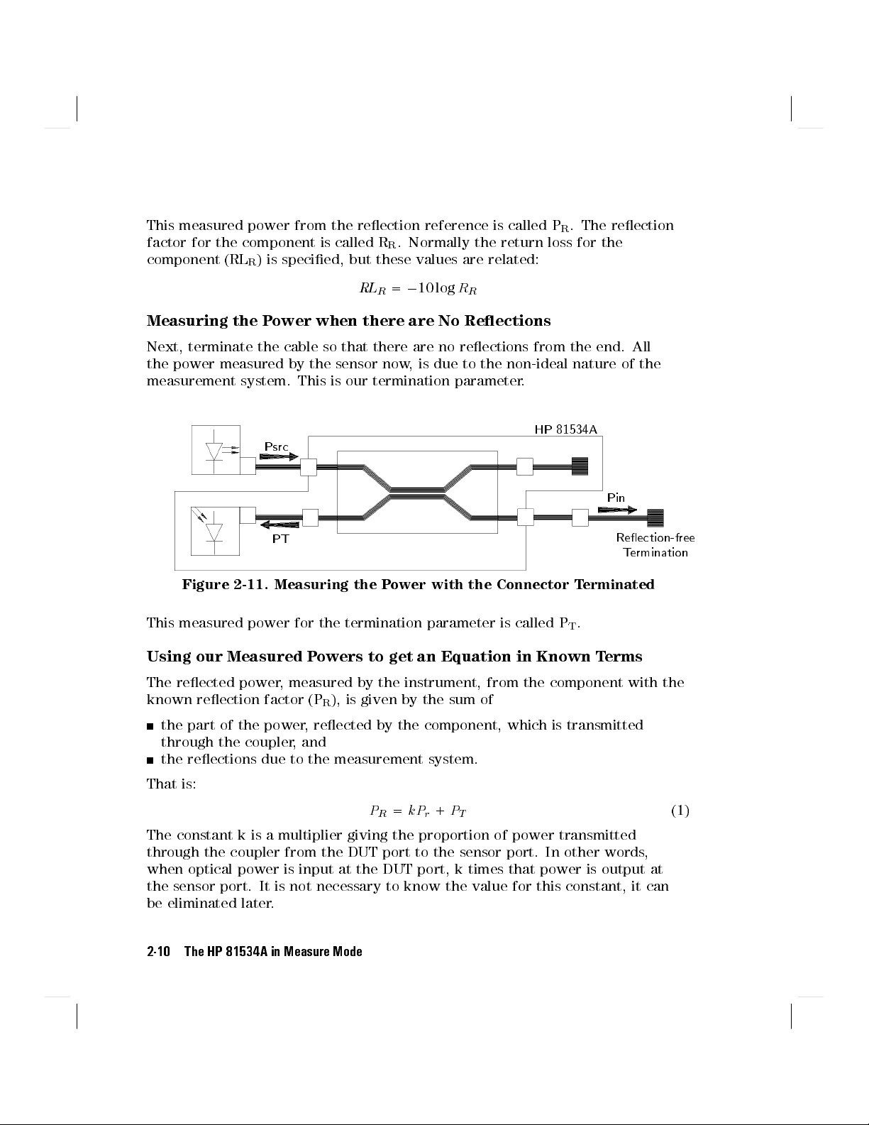
Measuring the Power when there are No Reections
Next, terminate the cable so that there are no reections from the end. All
the power measured by the sensor now, is due to the non-ideal nature of the
measurement system. This is our termination parameter.
HP 81534A
Psrc
Pin
PT
Reection-free
Termination
Figure 2-11. Measuring the Power with the Connector Terminated
This measured power for the termination parameter is called PT.
Using our Measured Powers to get an Equation in Known Terms
The reected power, measured by the instrument, from the component with the
known reection factor (PR), is given by the sum of
the part of the power, reected by the component, which is transmitted
through the coupler, and
the reections due to the measurement system.
That is:
PR=
kPr+
P
T
The constant k is a multiplier giving the proportion of power transmitted
through the coupler from the DUT port to the sensor port. In other words,
when optical power is input at the DUT port, k times that power is output at
the sensor port. It is not necessary to know the value for this constant, it can
be eliminated later.
2-10 The HP 81534A in Measure Mode
(1)
Here, the value for the reection factor of the component is known. The power
reected by the component is given by multiplying the incident power by the
reection factor. That is:
Pr=
PinR
R
By substituting this into equation number (1) it eliminates the value for the
power reected at the component, which cannot be measured directly. It does
introduce another power that cannot be measured directly (the power incident
on the component). This value is constant for the measurement system and can
be eliminated later.
PR=k(
PinRR)+
P
T
This equation can be changed around to give:
PR0
P
kPin=
T
R
R
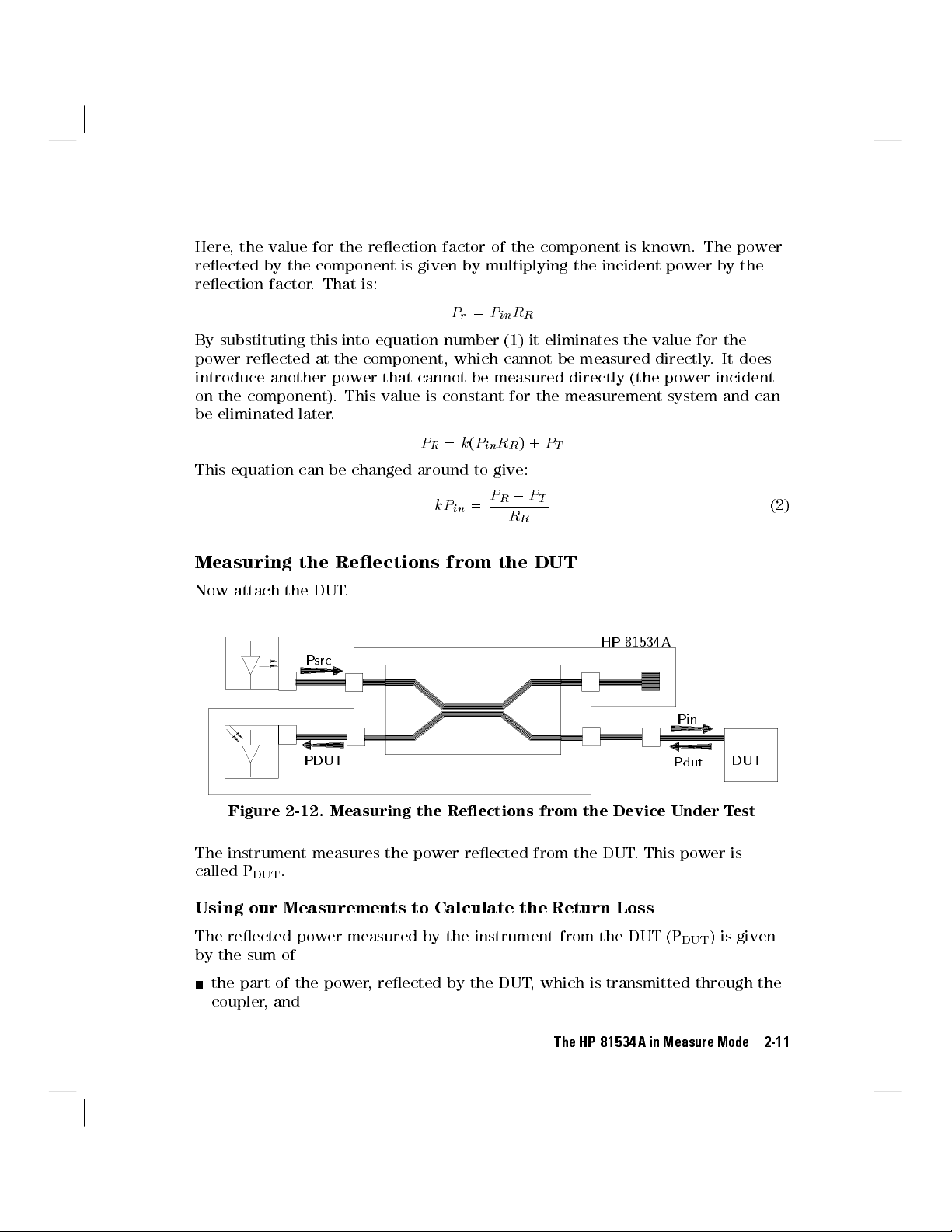
Measuring the Reections from the DUT
Now attach the DUT.
HP 81534A
Psrc
Pin
PDUT DUT
Pdut
Figure 2-12. Measuring the Reections from the Device Under Test
The instrument measures the power reected from the DUT. This power is
called P
DUT
.
(2)
Using our Measurements to Calculate the Return Loss
The reected power measured by the instrument from the DUT (P
DUT
) is given
by the sum of
the part of the power, reected by the DUT, which is transmitted through the
coupler, and
The HP 81534A in Measure Mode 2-11
 Loading...