


Agilent 53200A Series
RF/Universal Frequency
Counter/Timers
Data Sheet
53210A 350 MHz RF Frequency Counter, 10 digits/sec
53220A 350 MHz Universal Frequency Counter/Timer, 12 digits/sec, 100 ps
53230A 350 MHz Universal Frequency Counter/Timer, 12 digits/sec, 20 ps

Imagine your counter doing More!
More Bandwidth
• 350 MHz baseband frequency
• 6 or 15 GHz optional microwave
channels
More Resolution & Speed
• 12 digits/sec
• 20 ps single-shot time resolution
• Up to 75,000 and 90,000 readings/
sec (frequency and time interval)
More Insight
• Datalog trend plot
• Cumulative histogram
• Built-in math analysis and statistics
• 1M reading memory and USB Flash
storage
More Connectivity
• LXI-C/Ethernet LAN, USB
• Optional GPIB interface
• Optional battery for portability and
timebase accuracy
More Measurement Capability
(53230A only)
• Continuous gap-free measurements
• Basic measurements and
timestamps for modulation domain
analysis (MDA)
• Optional pulse/burst microwave
measurement
Introduction
Frequency counters are depended
on in R&D and in manufacturing for
the fastest, most accurate frequency
and time interval measurements.
The 53200 Series of RF and universal
frequency counter/timers expands on
this expectation to provide you with
the most information, connectivity
and new measurement capabilities,
while building on the speed and
accuracy you’ve depended on with
Agilent’s decades of time and frequency measurement expertise.
Three available models offer resolution capabilities up to 12 digits/sec
single-shot frequency resolution on
a one second gate. Single-shot time
interval measurements can be
resolved down to 20 psec. All models
offer new built-in analysis and
graphing capabilities to maximize the
insight and information you receive.
Definitions
The following definitions apply to the specifications and characteristics
described throughout.
Specifi cation (spec)
The warranted performance of a calibrated instrument that has been stored for a
minimum of 2 hours within the operating temperature range of 0º C - 55º C and after a
45-minute warm up period. Automated calibration (*CAL?) performed within ±5ºC before
measurement. All specifi cations were created in compliance with ISO-17025 methods.
Data published in this document are specifi cations unless otherwise noted.
Typical (typ)
The characteristic performance, which 80% or more of manufactured instruments will
meet. This data is not warranted, does not include measurement uncertainty, and is
valid only at room temperature (approximately 23º C). Automated calibration (*CAL?)
performed within ±5º C before measurement.
Nominal (nom)
The mean or average characteristic performance, or the value of an attribute that is
determined by design such as a connector type, physical dimension, or operating speed.
This data is not warranted and is measured at room temperature (approximately 23º C).
Automated calibration (*CAL?) performed within ±5º C before measurement.
Measured (meas)
An attribute measured during development for purposes of communicating the expected
performance.
This data is not warranted and is measured at room temperature (approximately 23º C).
Automated calibration (*CAL?) performed within ±5º C before measurement.
Stability
Represents the 24-hour, ±1º C short-term, relative measurement accuracy.
Includes measurement error and 24-hour ± 1º C timebase aging error.
Accuracy
Represents the traceable measurement accuracy of a measurement for T
Includes measurement error, timebase error, and calibration source uncertainty.
Random measurement errors are combined using the root-sum-square method and are
multiplied by k for the desired confi dence level. Systematic errors are added linearly and
include time skew errors, trigger timing errors, and timebase errors as appropriate for
each measurement type.
T
CAL
Represents the ambient temperature of the instrument during the last adjustment to
calibration reference standards.
T
must be between 10º C to 45º C for a valid instrument calibration.
CAL
T
ACAL
Represents the temperature of the instrument during the last automated calibration
(*CAL?) operation.
All information in this document are subject to change without notice.
2
± 5º C.
CAL

Input Channel Characteristics
53210A 53220A 53230A
Input characteristics (nom)
Channels
Standard (DC - 350 MHz) Ch 1 Ch 1 & Ch 2
Optional (6 GHz or 15 GHz) Ch 2 Ch 3
Standard inputs (nom)
Frequency range
DC coupled DC (1 mHz) to 350 MHz (2.8 ns to 1000 sec)
AC coupled, 50 Ω1 or 1 MΩ 10 Hz - 350 MHz
Input
Connector Front panel BNC(f). Option 201 adds parallel rear panel BNC(f) inputs
Input impedance (typ) Selectable 1 M Ω ± 1.5% or 50 Ω ± 1.5% || <25 pF
Input coupling Selectable DC or AC
Input filter Selectable 100 kHz cut-off frequency low pass
10 Hz (AC coupling) cut-off frequency high pass filter
Amplitude range
Input range ±5 V (±50 V) full scale ranges
Sensitivity
Noise
Input event thresholds
Threshold levels ±5 V (±50 V) in 2.5 mV (25 mV) steps
Noise reject
Slope Selectable Positive or Negative
Auto-scale Acquires signal for current measurement channel,
Auto-level Selectable On or Off
Minimum signal frequency
for auto level
Minimum signal for auto
level
Maximum input
50 Ω damage level 1 W
50 Ω protection threshold Will not activate below 7.5 VpK
1 M Ω damage level DC - 5 kHz: 350 Vpk (AC + DC)
3,4
(typ) DC - 100 MHz: 20 mVpk
> 100 MHz: 40 mVpk
3
4
500 µVrms (max), 350 µVrms (typ)
Selectable On/ Off
selects range (5 V or 50 V), sets auto-level 50%
On: Sets auto-level (% of Vpp) operation
Occurs once for each INIT or after a timeout.
Measures signal Vpp and sets Trigger level to 50%
Off: Selectable user set level (Volts)
User selectable (Slow (50 Hz), Fast (10 kHz))
300 mVpp
50 Ω internal termination auto-protects
by switching to 1 M Ω
5 kHz - 100 kHz: Derate linearly to 10 Vpk (AC + DC)
>100 kHz: 10 Vpk (AC + DC)
2
3

Input Channel Characteristics continued
53210A 53220A 53230A
Optional Microwave Inputs (nom)
Frequency range
Option 106 100 MHz - 6 GHz
Option 115 300 MHz - 15 GHz
Input
Connector Front panel precision Type-N(f)
Option 203 moves the input connector to a rear panel SMA(f)
Input impedance (typ) 50 Ω ± 1.5% (SWR < 2.5)
Input coupling AC
Continuous wave
amplitude range
Option 106 Autoranged to +19 dBm max. (2 Vrms)
Option 115 Autoranged to +13 dBm max. (1.0 Vrms)
Sensitivity (typ)
Input event thresholds
Level range Auto-ranged for optimum sensitivity and bandwidth
AM tolerance (CW only) 50% modulation depth
Maximum input
Damage level > +27 dBm (5 Vrms)
5
6 GHz (Opt 106): -27 dBm (10 mVrms)
15 GHz (Opt 115):
0.3 GHz – 2 GHz: -23 dBm
2 GHz – 13 GHz: -26 dBm
13 GHz – 15 GHz: -21 dBm
1. AC coupling occurs after 50 ohm termination
2. When ordered with optional rear terminals, the standard/baseband channel inputs are active on both the front and rear of the
universal counter though the specifications provided only apply to the rear terminals. Performance for the front terminals with rear
terminals installed is not specified.
3. Multiply value(s) by x10 for the 50 V range.
4. Stated specification assumes Noise Reject OFF. Noise Reject ON doubles the sensitivity minimum voltage levels.
5. Assumes sine wave.
4

Measurement Characteristics
53210A 53220A 53230A
Measurement range (nom)
Frequency, period (average) measurements
Common
Channels Ch 1 or optional Ch 2 Ch 1, Ch 2 or optional Ch 3
Digits/s 10 digits/s 12 digits/s 12 digits/s
Maximum display
Resolution
1
Measurement technique Reciprocal Reciprocal and resolution
Signal type Continuous Wave (CW) CW and pulse/burst
Level & slope Automatically preset or user selectable
Gate Internal or external
Gate time
Advanced gating
2
3
FM tolerance ± 50%
Frequency, period
Range9 DC (1 mHz) to 350 MHz (2.8 ns to 1000 s)
Microwave input (optional) Option 106 - 100 MHz to 6 GHz (166 ps to 10 ns)
Frequency ratio
4
Range 1015 Displayable range
Timestamp/modulation domain measurements
Sample rate
5
#Edges/ timestamp N/A N/A Auto-acquired per
Acquisition length N/A N/A up to 1 MSa or
Time interval (single-shot) measurements
Common
Channels N/A Ch 1 or 2
Single-shot time resolution N/A 100 ps 20 ps
Gating N/A Internal or external gate
Slope N/A Independent start, stop slopes
Level N/A Independent start, stop slopes
Channel-to-channel time
skew (typ)
12 digits 15 digits 15 digits
enhanced
1 ms to 1000 s in 10 µs
steps
100 µs to 1000 s in 10 µs
steps
1 µs to 1000 s in 1 µs steps
N/A Start delay (time or events) and stop hold-off
(time or events)
Option 115 - 300 MHz to 15 GHz ( 66 ps to 3.3 ns)
N/A N/A 1 MSa/s, 800 kSa/s,
11
Start delay (time or events) and stop hold-off
(time or events)
N/A 100 ps 50 ps
Reciprocal, resolution-
enhanced or continuous
(gap-free)
(Option 150)
100 kSa/s, 10 kSa/s
acquisition
100,000 s (max)
5

Measurement Characteristics continued
53210A 53220A 53230A
Time interval A to B, B to A
9
Range
Time interval A or B
Range N/A 2 ns to 100,000 s (min)
Minimum width N/A 2 ns
Minimum edge repetition
rate
Level & slope N/A Auto-level or user selectable
Single-period, pulse-width, rise time, fall time
Range N/A 0 s to 1000 s
Minimum width N/A 2 ns
Minimum edge repetition
Rate
Level & slope N/A Auto-level or user selectable
Duty
Range N/A .000001 to .999999 or 0.0001% to 99.9999%
Minumim width N/A 2 ns
Level & slope N/A Auto-level or user selectable
Phase A to B, B to A
6
Range
Totalize measurements
Channels N/A Ch 1 or Ch 2
9
Range
Rate N/A 0 - 350 MHz
Gating N/A Continuous, timed, or external gate input
Level measurements
Voltage level - standard
input channels
Microwave power level
(microwave channel option)
N/A -1 ns to 100,000 s (nom)
-0.5 ns to 100,000 s (min)
N/A 6 ns
N/A 6 ns
N/A -180.000º to 360.000º
N/A 0 to 1015 events
Gate accuracy is 20 ns
±5.1 Vpk with 2.5 mV resolution or ±51 Vpk with 25 mV resolution
0 to 4 relative signal power
6
Measurement Characteristics continued
53210A 53220A 53230A
Pulse/burst frequency and pulse envelope detector (Option 150)
Pulse/burst measurements N/A N/A Carrier frequency, carrier
Pulse/burst width
N/A N/A >200 ns
for carrier frequency
measurements
Minimum pulse/burst
10
N/A N/A >50 ns
width for envelope
measurements
Acquisition N/A N/A Auto, Manual7
PRF, PRI range N/A N/A 1 Hz – 10 MHz
Pulse detector response
time (typ)
8
N/A N/A 15 ns rise, fall
Pulse width accuracy (typ) N/A N/A 20 ns + (2*carrier period)
Power ratio (typ) N/A N/A >15 dB
Power range and
N/A N/A +13 dBm (1 Vrms) to
sensitivity (sinusoidal) (typ)
12
period, pulse repetition
interval (PRI), pulse repeti-
tion frequency (PRF), posi-
tive and negative width
Narrow: <17 us
Wide: >13 us
-13 dBm (50 mVrms)
1. Maximum display resolution for frequency and period. Totalize display resolution is 15 digits, time interval based measurements
are 12 digits.
2. Continuous, gap-free measurements limits the gate time setting to 10 µs to 1000 s in 10 µs steps.
3. Refer to the gate characteristics section for more details on advanced gate capabilities.
4. Measurements on each input channel are performed simultaneously using one gate interval. The actual measurement gate interval
on each channel will be synchrounous with edges of each input signal.
5. Maximum sample rate. Actual sample rate will be limited by the input signal edge rate for signals slower than the selected sample
rate. Maximum timestamp rate offers minimal FM tolerance. If high FM tolerance is required, use lower timestamp rates.
6. Assumes two frequencies are identical, only shifted in phase.
7. Manual control of gate width and gate delay are allowed only for wide pulsed mode.
8. For pulsed signals > -7 dBm (100 mVrms) while gated on.
9. For totalize, time interval and frequency measurements, you may get measurement readings beyond the
range stated, but the accuracy of those readings is not specified.
10. Applies when burst width * Carrier Freq >80.
11. Specifications apply if measurement channels are in 5 V range, DC coupled, 50 ohm terminated and at fixed level for: time interval
single and dual channel, pulse width, duty, phase, single period and rise/fall time measurements.
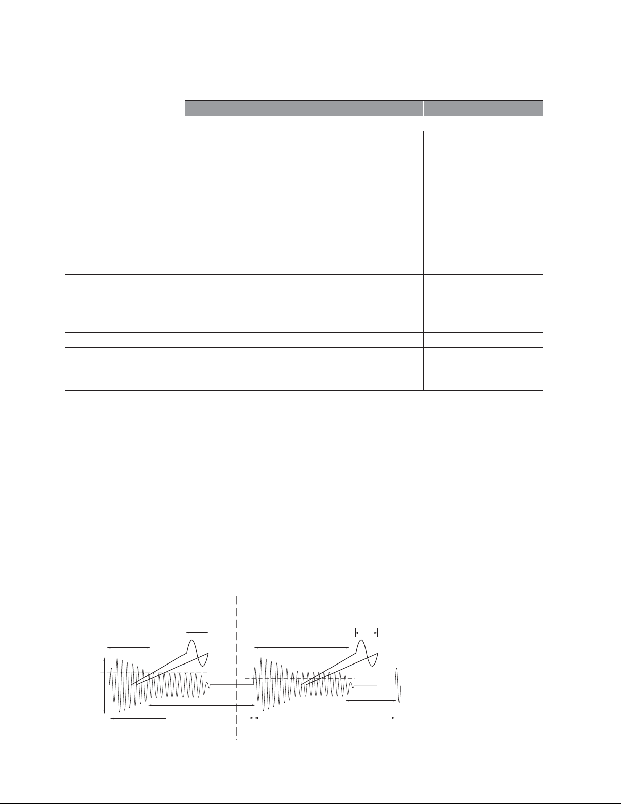
12. Option 150 microwave pulse/burst measurement descriptions:
+ width burst (on)
- 6 dB
p-p
amplitude
-6 dB Detector Level
Burst carrier frequency
- width burst (off)
PRF
PRI = 1/PRF
-12
-6 dB Detector Level
+ width burst (on)
PRI = 1/PRF
Burst carrier frequency
- 12 dB
- width burst (off)
PRF
7
 Loading...