


HP 4349B 4-Channel High Resistance Meter
Operation Manual
SERIAL NUMBERS
This manual applies directly to instruments with serial
number prex JP1KD, or rmware revision 1.04.
For additional important information about serial
numbers, read \Serial Number" in Appendix A.
HP Part No. 04349-90040
Printed in Japan August 1998
Fourth Edition
Notice
The information contained in this document is subject to change without notice.
This document contains proprietary information that is protected by copyright. All rights are
reserved. No part of this document may be photocopied, reproduced, or translated to another
language without the prior written consent of the Hewlett-Packard Company.
Hewlett-Packard Japan, LTD.
Kobe Instrument Division
1-3-2, Murotani, Nishi-Ku, Kobe-shi,
Hyogo, 651-2241 Japan
c
1996,1998 Hewlett-Packard Japan, Ltd.

HP 4349B
Manual Printing History
March 1996
December 1996
June 1998
August 1998
::::::: :::::: ::::::: ::::::: :::::: ::::::: ::::::: :::::: ::::::: ::::::: ::::::
:::::: ::::::: ::::::: :::::: ::::::: ::::::: :::::: ::::::: ::::::: :::::: ::::::: :
:::::: ::::::: :::::: ::::::: ::::::: :::::: ::::::: ::::::: :::::: ::::::: ::::
::::: ::::::: :::::: ::::::: ::::::: :::::: ::::::: ::::::: :::::: ::::::: :
First Edition
Second Edition
Third Edition
Fourth Edition
iii
HP 4349B
Safety Summary
The following general safety precautions must be observed during all phases of operation,
service, and repair of this instrument. Failure to comply with these precautions or with specic
WARNINGS
elsewhere in this manual may impair the protection provided by the equipment.
In addition it violates safety standards of design, manufacture, and intended use of the
instrument.
The Hewlett-Packard Company assumes no liability for the customer's failure to comply with
these requirements.
Note
HP 4349B comply with INSTALLATION CATEGORY II and POLLUTION
DEGREE 2 in IEC1010-1. HP 4349B are INDOOR USE product.
Note
LEDs in HP 4349B are Class 1 in accordance with IEC825-1.
CLASS 1 LED PRODUCT
Ground The Instrument
To avoid electric shock hazard, the instrument chassis and cabinet must be connected to a
safety earth ground by the supplied power cable with earth blade
.
DO NOT Operate In An Explosive Atmosphere
Do not operate the instrument in the presence of ammable gasses or fumes
. Operation of any
electrical instrument in such an environment constitutes a denite safety hazard.
Keep Away From Live Circuits
Operating personnel must not remove instrument covers. Component replacement and internal
adjustments must be made by qualied maintenance personnel. Do not replace components
with the power cable connected. Under certain conditions, dangerous voltages may exist even
with the power cable removed. To avoid injuries, always disconnect power and discharge
circuits before touching them.
DO NOT Service Or Adjust Alone
Do not attempt internal service or adjustment unless another person, capable of rendering rst
aid and resuscitation, is present.
DO NOT Substitute Parts Or Modify Instrument
Because of the danger of introducing additional hazards, do not install substitute parts
or perform unauthorized modications to the instrument. Return the instrument to a
Hewlett-Packard Sales and Service Oce for service and repair to ensure that safety features
are maintained.
iv

HP 4349B
Dangerous Procedure Warnings
Warnings
, such as the example below, precede potentially dangerous procedures throughout
this manual. Instructions contained in the warnings must be followed.
Warning
Dangerous voltages, capable of causing death, are present in this
instrument. Use extreme caution when handling, testing, and adjusting
this instrument.
v
HP 4349B
Certication
Hewlett-Packard Company certies that this product met its published specications at the
time of shipment from the factory. Hewlett-Packard further certies that its calibration
measurements are traceable to the United States National Institute of Standards and
Technology, to the extent allowed by the Institution's calibration facility, or to the calibration
facilities of other International Standards Organization members.
Warranty
This Hewlett-Packard instrument product is warranted against defects in material and
workmanship for a period of one year from the date of shipment, except that in the case of
certain components listed in
General Information
of this manual, the warranty shall be for the
specied period. During the warranty period, Hewlett-Packard Company will, at its option,
either repair or replace products that prove to be defective.
For warranty service or repair, this product must be returned to a service facility designated by
HP. Buyer shall prepay shipping charges to HP and HP shall pay shipping charges to return the
product to Buyer. However, Buyer shall pay all shipping charges, duties, and taxes for products
returned to HP from another country.
HP warrants that its software and rmware designated by HP for use with an instrument will
execute its programming instruction when property installed on that instrument. HP does not
warrant that the operation of the instrument, or software
, or rmware will be uninterrupted or
error free.
Limitation Of Warranty
The foregoing warranty shall not apply to defects resulting from improper or inadequate
maintenance by Buyer, Buyer-supplied software or interfacing, unauthorized modication or
misuse, operation outside the environmental specications for the product, or improper site
preparation or maintenance.
No other warranty is expressed or implied. HP specically disclaims the implied warranties
of merchantability and tness for a particular purpose.
vi
HP 4349B
Exclusive Remedies
The remedies provided herein are buyer's sole and exclusive remedies. HP shall not be liable
for any direct, indirect, special, incidental, or consequential damages, whether based on
contract, tort, or any other legal theory.
Assistance
Product maintenance agreements and other customer assistance agreements are available for
Hewlett-Packard products.
For any assistance, contact your nearest Hewlett-Packard Sales and Service Oce.Addresses
are provided at the back of this manual.
vii

HP 4349B
Safety Symbols
General denitions of safety symbols used on equipment or in manuals are listed below.
Instruction manual symbol: the product is marked with this symbol when it is
necessary for the user to refer to the instruction manual.
Alternating current.
Direct current.
On (Supply).
O (Supply).
Frame or chassis terminal
This
Warning
condition or the like, which, if not correctly performed or adhered to, could
result in injury or death to personnel.
sign denotes a hazard. It calls attention to a procedure, practice,
This
Caution
condition or the like, which, if not correctly performed or adhered to
result in damage to or destruction of part or all of the product.
Note
practice, condition or the like, which is essential to highlight.
denotes important information. It calls attention to a procedure
sign denotes a hazard. It calls attention to a procedure
, practice,
, could
,
viii
HP 4349B
Herstellerbescheinigung
GERXSCHEMISSION
LpA<70 dB
am Arbeitsplatz
normaler Betrieb
nach DIN 45635 T.19
Manufacturer's Declaration
ACOUSTIC NOISE EMISSION
LpA<70 dB
operator position
normal operation
per ISO 7779
ix
HP 4349B
Contents of this Manual
Chapter 1, Getting Started
Provides the product overview and basic measurement procedure. First time users of the
HP 4349B should read this chapter rst.
Chapter 2, Operating the HP 4349B
Shows how to operate the HP 4349B from its front panel. Refer to this chapter when you wish
to learn about operations using the front panel keys.
Chapter 3, Function Reference
Describes all functions of this instrument. Refer to this chapter when you wish to learn about
the functions of the front and rear panel keys and terminals.
Chapter 4, Remote Operation
Shows how to remotely operate the HP 4349B. Refer to this chapter when you wish to learn
about the procedures for remotely operating the HP 4349B via the HP-IB
.
Chapter 5, HP-IB Reference
Contains complete information on remotely operating the HP 4349B via the HP-IB
this chapter when you wish to learn about the HP-IB commands
trigger system, and data transmission format.
Chapter 6, Application Measurement
Provides a measurement example using the HP 4349B.
Chapter 7, Measurement Basics
Provides information for eective operations.
Chapter 8, General Information
Provides specications, reference data, and other general information.
Chapter 9, Maintenance
Describes how to verify the specications.
, status reporting mechanism,
. Refer to
x
HP 4349B
Appendix A, Manual Changes
Contains information on using the HP 4349Bs which were manufactured before this manual
was printed.
Appendix B, Handler Interface Installation
Contains information which is required for using the handler interface. Before using the
handler interface, read this appendix and set the handler interface input/output signal.
Appendix C, Overload/No-Contact Operations
The summary of operations when the HP 4349B detects OVLD (Overload), or N.C. (No-Contact).
xi


Contents
1. Getting Started
Introduction .. ...... ...... ...... ...... .... 1-1
Overview .... ...... ...... ...... ...... ..... . 1-2
Features ...... ...... ...... ...... ...... ... 1-2
Accessories Available . . . . . . . . . . . . . . . . . . . . . . . . . . . . 1-3
Options Available ............................. 1-3
Front Panel .. ...... ...... ...... ...... ...... 1-4
Display .................................. 1-6
Rear Panel ................................ 1-7
Initial Inspection . . . . . . . . . . . . . . . . . . . . . . . . . . . . . . .
Ventilation Requirements . . . . . . . . . . . . . . . . . . . . . . . . . . .
Instruction for Cleaning ...... ...... ...... ...... ...
Power Cable . . . . . . . . . . . . . . . . . . . . . . . . . . . . . . . . .
Preparation for Use .............................
Power Requirements . . . . . . . . . . . . . . . . . . . . . . . . . . . .
1-8
1-8
1-8
1-9
1-11
1-11
Fuse . . . . . . . . . . . . . . . . . . . . . . . . . . . . . . . . .
Turning ON the HP 4349B .........................
Using Front Panel Keys ...........................
Direct Execution Keys . . . . . . . . . . . . . . . . . . . . . . . . . . .
Toggle Keys .... ...... ...... ...... ...... ....
Selection Keys . . . . . . . . . . . . . . . . . . . . . . . . . . . . . . .
Value Setup Keys .............................
Numeric Keys . . . . . . . . . . . . . . . . . . . . . . . . . . . . . .
Maximum and Minimum Keys ......................
Left/Down and Right/Up Arrow Keys . . . . . . . . . . . . . . . . . . . 1-15
Back Space Key ...... ...... ...... ...... ..... 1-15
If you have any problems .......................... 1-16
2. Operating the HP 4349B
Introduction . . . . . . . . . . . . . . . . . . . . . . . . . . . . . . . . .
External Voltage Source ...........................
Test Leads . . . . . . . . . . . . . . . . . . . . . . . . . . . . . . . . . .
Specications .......... ...... ...... ...... ...
Installation . . . . . . . . . . . . . . . . . . . . . . . . . . . . . . .
Measurement Conguration ........ ...... ...... .....
To Reset the HP 4349B . . . . . . . . . . . . . . . . . . . . . . . . . . .
ToPerform the OPEN Correction Function ................. 2-5
To Select a Measurement Parameter . . . . . . . . . . . . . . . . . . . . . 2-5
To Select the Channel ...........................
To Enter the Voltage Value . . . . . . . . . . . . . . . . . . . . . . . . .
To Select the Measurement Range . . . . . . . . . . . . . . . . . . . . . .
To Select the Measurement Time Mode ...................
To Set the Averaging Rate .........................
1-11
1-12
1-13
1-13
1-13
1-13
1-14
1-14
1-15
2-1
2-2
2-2
2-2
2-3
2-5
2-5
2-6
2-6
2-6
2-7
2-7
Contents-1
To Set the Trigger Delay Time ....................... 2-7
To Set the Contact Check . . . . . . . . . . . . . . . . . . . . . . . . . . 2-8
Reading the Limit Data of Contact Check Function ............ 2-8
Reading the Capacitance Data at DUT Measurement . . . . . . . . . . . . 2-10
To Set the Beeper Mode .......................... 2-10
Saving and Recalling Instrument Settings .................. 2-11
Making a Measurement . . . . . . . . . . . . . . . . . . . . . . . . . . . . 2-12
Triggering a Measurement .. ...... ...... ...... ..... 2-12
To Use the Comparator Function ...................... 2-12
To Select the Display Mode and Display Digits . . . . . . . . . . . . . . . . 2-14
To Change the Measurement Settings Display ................ 2-14
Locking Out the Front Panel Keys .... ...... ..... ...... 2-15
Selecting Local Mode . . . . . . . . . . . . . . . . . . . . . . . . . . . . 2-15
Setting the HP-IB Address ......................... 2-15
Printing Measurement Data . . . . . . . . . . . . . . . . . . . . . . . . . 2-15
ToTest the HP 4349B ............................ 2-16
Performing a Self-Test ........................... 2-16
Testing the Front Panel Keys' Functionality ...... ..... ...... 2-16
If Your HP 4349B Has a Problem ....................... 2-17
If the Display is Blank and the HP 4349B Appears Dead ........... 2-17
If an Error Message is Displayed ......................
If the HP 4349B does not Accept Any Key Input . . . . . . . . . . . . . . .
If the Resistance Value Is Always 0 ....................
3. Function Reference
Introduction . . . . . . . . . . . . . . . . . . . . . . . . . . . . . . . . .
Front Panel .................................
Display ..................................
LINE Switch . . . . . . . . . . . . . . . . . . . . . . . . . . . . . . . .
Chassis Terminal . . . . . . . . . . . . . . . . . . . . . . . . . . . . . .
2-17
2-17
2-17
3-1
3-2
3-2
3-3
3-3
INPUT (Ch1, Ch2, Ch3, and Ch4) Terminals . . . . . . . . . . . . . . .
Channel key
.............................
Voltage Entry Key ...... ...... ...... ..... ...
Measurement Time Key
....................... 3-4
3-3
3-4
3-4
Average Key ...... ...... ...... ...... .. 3-4
Measurement Parameter Key
...... ...... ...... ... 3-4
Show Setting Key .......................... 3-4
Display Mode Key
.......................
Auto/Hold Range Key ........................
Range Setup Key ........................
Comparator Limit Key ......................
Trigger Key ...... ...... ..... ...... ......
Local Key
Address Key
.............................. 3-6
...... ...... ...... ...... .. 3-6
Trigger Mode Key ..........................
Delay Key
...........................
3-5
3-5
3-5
3-5
3-6
3-6
3-7
Contents-2
Save Key ............................ 3-7
Recall Key
...... ...... ...... ...... ...... 3-7
Right/Up Arrow Key and Left/Down Arrow Key ...... .... 3-7
0, . . . , 9, .(point),0(minus) Key ... ...... .... 3-7
BLUE Shift Key ........ ...... ...... ...... . 3-7
Exponential Key
........................... 3-8
Back Space Key ........ ...... ...... ...... . 3-8
Enter Key .............................. 3-8
Minimum Key
.......................... 3-8
Maximum Key ......................... 3-8
Comparator Key ......................... 3-8
Contact Check Key ...... ...... ...... ..... 3-9
Open Key .. ...... ...... ...... ..... ... 3-9
Key Lock Key ..........................
Reset Key ............................
Conguration Key ........................
Rear Panel .................................
External Trigger . . . . . . . . . . . . . . . . . . . . . . . . . . . . . .
3-9
3-10
3-11
3-12
3-12
LINE Fuse Holder .... ...... ...... ..... .....
LINE Voltage Selector ...........................
Serial Number Plate .. ...... ...... ...... ...... ..
Power Cord Receptacle . . . . . . . . . . . . . . . . . . . . . . . . . . .
Power Cord ...............................
Handler Interface .............................
Specications ..............................
HP-IB Interface .......... ...... ...... ...... ..
Theory of Operation . . . . . . . . . . . . . . . . . . . . . . . . . . . . . 3-19
Overall Measurement Theory . . . . . . . . . . . . . . . . . . . . . . . . 3-19
Overall Block Diagram . . . . . . . . . . . . . . . . . . . . . . . . . . . 3-20
4. Remote Operation
Introduction . . . . . . . . . . . . . . . . . . . . . . . . . . . . . . . . .
Getting Started ...... ...... ...... ...... ...... .
Input/Output Statements . . . . . . . . . . . . . . . . . . . . . . . . . .
Reading the HP-IB Address . . . . . . . . . . . . . . . . . . . . . . . . .
Sending a Remote Command .... ...... ...... ...... ..
Returning to Local Mode . . . . . . . . . . . . . . . . . . . . . . . . . .
Query Commands .............................
Getting Data from the HP 4349B ........ ...... ...... ..
To Control the HP 4349B from an External Computer ............. 4-4
To Set Up the HP 4349B ........................... 4-5
To Reset the HP 4349B . . . . . . . . . . . . . . . . . . . . . . . . . . .
To Set the LINE Frequency . . . . . . . . . . . . . . . . . . . . . . . . .
ToPerform the OPEN Correction ......................
To Select the Measurement Parameter . . . . . . . . . . . . . . . . . . . .
To Enter Voltage Value . . . . . . . . . . . . . . . . . . . . . . . . . . .
3-13
3-13
3-13
3-13
3-13
3-14
3-14
3-18
4-1
4-2
4-2
4-2
4-2
4-3
4-3
4-3
4-5
4-5
4-5
4-5
4-6
Contents-3
To Select the Measurement Range . . . . . . . . . . . . . . . . . . . . . . 4-6
To Set the Measurement Time Mode . . . . . . . . . . . . . . . . . . . . . 4-6
To Set the Averaging rate . . . . . . . . . . . . . . . . . . . . . . . . . . 4-7
To Set the Trigger Delay time . . . . . . . . . . . . . . . . . . . . . . . . 4-7
ToPerform the Contact Check ....................... 4-7
To Set the Beeper Mode .......................... 4-7
To Lock Out the Front Panel Keys ...... ...... ..... .... 4-7
To Use the Comparator Function ...................... 4-8
ToWait Until Previously Sent Commands are Completed ........... 4-8
To Get the Current Instrument Settings ................... 4-9
To Save and Recall Instrument Settings .... ...... ...... ... 4-9
To Trigger a Measurement .......................... 4-10
To Retrieve Data Eciently .. ...... ...... ...... ..... 4-12
To Transfer Data Using the Real Data Format .. ...... ...... .. 4-12
To Use Data Buer . . . . . . . . . . . . . . . . . . . . . . . . . . . . . 4-12
Other Features ............................... 4-13
To test the HP 4349B . . . . . . . . . . . . . . . . . . . . . . . . . . . . 4-13
To Report the Instrument's Status . . . . . . . . . . . . . . . . . . . . . . 4-13
If You Have a Problem . . . . . . . . . . . . . . . . . . . . . . . . . . . . 4-15
If the HP 4349B Hangs Up When You Send the
ABORt
Command ....... 4-15
5. HP-IB Reference
Introduction . . . . . . . . . . . . . . . . . . . . . . . . . . . . . . . . .
HP-IB Commands ..............................
Common Commands . . . . . . . . . . . . . . . . . . . . . . . . . . . .
Subsystem Commands ...........................
Subsystem Command Tree ..........................
Program Message Syntax . . . . . . . . . . . . . . . . . . . . . . . . . . .
Case .. ...... ...... ...... ...... ..... ....
Program Message Terminator . . . . . . . . . . . . . . . . . . . . . . . .
Subsystem Command Syntax . . . . . . . . . . . . . . . . . . . . . . . .
Common Command Syntax . . . . . . . . . . . . . . . . . . . . . . . . .
Parameters ................................
Parameter Types . . . . . . . . . . . . . . . . . . . . . . . . . . . . .
Sux . . . . . . . . . . . . . . . . . . . . . . . . . . . . . . . . . .
Multiple Messages ............................. 5-7
Query and Response Message Syntax ...... ...... ..... ... 5-7
Command Reference . . . . . . . . . . . . . . . . . . . . . . . . . . . . . 5-8
Notations ................................. 5-8
ABORt Command .............................. 5-9
:ABORt ...... ...... ...... ...... ...... ....
CALCulate Subsystem ............................
:CALCulatef1j2j3j4g:LIMit:BEEPer:CONDitionfFAILjPASSg........ 5-10
:CALCulatef1j2j3j4g:LIMit:BEEPer[:STATe]fONjOFFj1j0g........ 5-10
:CALCulatef1j2j3j4g:LIMit:CLEar . . . . . . . . . . . . . . . . . . . . . .
:CALCulatef1j2j3j4g:LIMit:FAIL? ......................
:CALCulatef1j2j3j4g:LIMit:LOWer[:DATA]<numeric value>...... ... 5-11
:CALCulatef1j2j3j4g:LIMit:LOWer:STATefONjOFFj1j0g...... ... 5-11
:CALCulatef1j2j3j4g:LIMit:STATefONjOFFj1j0g...... ...... . 5-11
:CALCulatef1j2j3j4g:LIMit:UPPer[:DAT
:CALCulatef1j2j3j4g:LIMit:UPPer:STATefONjOFFj1j0
A]<numeric value>...... ... 5-12
g
...... ...
CALCulatef1j2j3j4g:PATH?.........................
DATA Subsystem . . . . . . . . . . . . . . . . . . . . . . . . . . . . . . .
:DATA[:DATA]? DBUF ...........................
:DATA:FEED DBUF,<data handle>.....................
5-1
5-1
5-1
5-1
5-4
5-5
5-5
5-5
5-5
5-5
5-5
5-6
5-7
5-9
5-10
5-11
5-11
5-12
5-12
5-13
5-13
5-14
Contents-4
:DATA:FEED:CONTrol DBUF,fALWaysjNEVerg................ 5-14
:DATA:POINts DBUF,<numeric value>................... 5-14
DISPlay Subsystem . . . . . . . . . . . . . . . . . . . . . . . . . . . . . . 5-15
:DISPlay:ENABlefONjOFFj1j0g...... ...... ...... .. 5-15
:DISPlay:WINDowf1j2j3j4g[:STATe]fONjOFFj1j0g............ 5-15
:DISPlay:WINDowf1j2j3j4g:TEXT1:PAGEf1j2g.............. 5-15
:DISPlay:WINDowf1j2j3j4g:TEXT1:DIGitf3j4j5g............. 5-16
:DISPlay:WINDowf1j2j3j4g:TEXT2:PAGEf1j2j3g...... ...... . 5-16
FETCh? Query ........ ...... ...... ..... ...... 5-17
:FETCh? ................................. 5-17
FORMat Subsystem ............................. 5-18
:FORMat[:DATA]fASCiijREAL[,64]
g
...... ..... ...... .. 5-18
INITiate Subsystem ........ ...... ..... ...... .... 5-19
:INITiate[:IMMediate] ........................... 5-19
:INITiate:CONTinuousfONjOFFj1j0g.................. 5-19
SENSe Subsystem .............................. 5-20
[:SENSe]:AVERage:COUNt<numeric value>...... ...... .... 5-20
[:SENSe]:AVERage[:STATe]fONjOFFj1j0g................ 5-20
[:SENSe]:CORRection:COLLect[:ACQuire] OFFSet .......... .... 5-20
[:SENSe]:CORRection:DATAf1j2j3j4g? OFFSet .... ...... ...... 5-21
[:SENSe]:CORRection:DATAf1j2j3j4g? SCAPacitance .............
[:SENSe]:CORRection[:STATe]fONjOFFj1j0g..............
[:SENSe]:CONTact:DATAf1j2j3j4g?......................
[:SENSe]:CONTact:LIMitf1j2j3j4g?......................
[:SENSe]:CONTact:OFFSetf1j2j3j4g<
numeric
value>............
[:SENSe]:CONTact:VERifyfONjOFFj1j0g................
[:SENSe]:CURRent:APERture<numeric value>[MSjS]............
[:SENSe]:CURRent:RANGef1j2j3j4g:AUTOfONjOFFj1j0
[:SENSe]:CURRent:RANGef1j2j3j4g[:UPPer]<numeric
g
...... .. 5-22
value>[PAjNAjUAjMAjA] 5-23
[:SENSe]:FUNCtion<sensor function>...... ...... ...... .
SOURce Subsystem .............................
:SOURce:VOLTagef1j2j3j4g[:LEVel][:IMMediate][:AMPLitude]<numeric
value
STATus Subsystem . . . . . . . . . . . . . . . . . . . . . . . . . . . . . .
:STATus:OPERation[:EVENt]? . . . . . . . . . . . . . . . . . . . . . . . .
:STATus:OPERation:CONDition? ...... ...... ..... .....
5-21
5-21
5-21
5-21
5-22
5-22
5-22
5-23
5-24
>
5-24
5-25
5-25
5-25
:STATus:OPERation:ENABle<numeric value>...... ...... ... 5-25
:STATus:PRESet .. ...... ...... ...... ...... .... 5-26
:STATus:QUEStionable[:EVENt]? ...................... 5-26
:STATus:QUEStionable:CONDition? ..................... 5-26
:STATus:QUEStionable:ENABle<numeric value>...... ...... .. 5-26
SYSTem Subsystem . . . . . . . . . . . . . . . . . . . . . . . . . . . . . .
:SYSTem:BEEPer[:IMMediate] . . . . . . . . . . . . . . . . . . . . . . . .
:SYSTem:BEEPer:STATefONjOFFj1j0g.................
:SYSTem:ERRor? . . . . . . . . . . . . . . . . . . . . . . . . . . . . . .
:SYSTem:KLOCkfONjOFFj1j0
g
....................
:SYSTem:LFRequency<numeric value>..................
:SYSTem:PRESet . . . . . . . . .
...... ...... ...... ...
:SYSTem:VERSion? . . . . . . . . . . . . . . . . . . . . . . . . . . . . .
5-27
5-27
5-27
5-27
5-27
5-27
5-28
5-28
TRIGger Subsystem ........ ...... ..... ...... .... 5-29
:TRIGger:DELay<numeric value>[MSjS].................. 5-29
:TRIGger[:IMMediate] ...........................
:TRIGger:SOURcefBUSjEXTernaljINTernaljMANualg..........
Common Commands . . . . . . . . . . . . . . . . . . . . . . . . . . . . .
3
CLS ...... ...... ...... ...... ...... .....
3
ESE<numeric value>...... ...... ...... ...... ..
5-29
5-29
5-30
5-30
5-30
Contents-5
3
ESE? . . . . . . . . . . . . . . . . . . . . . . . . . . . . . . . . . . . 5-30
3
ESR? . . . . . . . . . . . . . . . . . . . . . . . . . . . . . . . . . . . 5-30
3
IDN? . . . . . . . . . . . . . . . . . . . . . . . . . . . . . . . . . . . 5-30
3
LRN? .................................. 5-30
3
OPC ................................... 5-30
3
OPC? . . . . . . . . . . . . . . . . . . . . . . . . . . . . . . . . . . . 5-31
3
OPT? . . . . . . . . . . . . . . . . . . . . . . . . . . . . . . . . . . . 5-31
3
RCL<numeric value>...... ...... ...... ..... ... 5-31
3
RST ...... ...... ...... ..... ...... ...... 5-31
3
SAV<numeric value>.......................... 5-31
3
SRE<numeric value>.......................... 5-31
3
SRE? . . . . . . . . . . . . . . . . . . . . . . . . . . . . . . . . . . . 5-31
3
STB? . . . . . . . . . . . . . . . . . . . . . . . . . . . . . . . . . . . 5-32
3
TRG ................................... 5-32
3
TST? . . . . . . . . . . . . . . . . . . . . . . . . . . . . . . . . . . . 5-32
3
WAI ........ ...... ...... ..... ...... .... 5-32
Status Reporting Structure . . . . . . . . . . . . . . . . . . . . . . . . . . 5-33
Service Request (SRQ) ........................... 5-33
Status Byte Register . . . . . . . . . . . . . . . . . . . . . . . . . . . . 5-34
Standard Event Status Register . . . . . . . . . . . . . . . . . . . . . . . 5-35
Standard Operation Status Group . . . . . . . . . . . . . . . . . . . . . .
Operation Status Register .........................
Questionable Status Register ........................
Trigger System ........ ...... ...... ...... .....
HP 4349B Trigger System Conguration . . . . . . . . . . . . . . . . . . .
Idle State .... ...... ...... ...... ...... ....
Initiate State ..............................
Event Detection State ..........................
Sequence Operation State ........................
Data Transfer Format ...... ...... ...... ...... ....
ASCii . . . . . . . . . . . . . . . . . . . . . . . . . . . . . . . . . . .
REAL . . . . . . . . . . . . . . . . . . . . . . . . . . . . . . . . . . .
5-36
5-37
5-37
5-38
5-38
5-38
5-39
5-39
5-39
5-40
5-40
5-41
6. Application Measurement
Introduction ..............................
High Throughput Measurement . . . . . . . . . . . . . . . . . . . . . . . . 6-2
Multi Test Voltages Measurement ....................... 6-5
Note on Measuring Insulation Resistance of Capacitors . . . . . . . . . . . . . 6-8
The External DC Voltage Source .... ...... ...... ...... 6-8
How to Select the Optimum Measurement Range . . . . . . . . . . . . . .
Additional Error Due to Voltage Source Noise ................
How to Reduce the Measurement Error . . . . . . . . . . . . . . . . . . .
Precharge Time and Wait Time .... ...... ...... ...... .
7. Measurement Basics
Introduction . . . . . . . . . . . . . . . . . . . . . . . . . . . . . . . . .
Insulation Resistance Measurement . . . . . . . . . . . . . . . . . . . . . .
Residual Charge Eect . . . . . . . . . . . . . . . . . . . . . . . . . . . 7-1
Absorption Phenomena .......................... 7-1
Voltage Coecient and Temperature Coecient ...............
Shielding .. ...... ...... ...... ...... ...... .
Contents-6
6-1
6-8
6-10
6-11
6-12
7-1
7-1
7-1
7-2

8. General Information
Introduction . . . . . . . . . . . . . . . . . . . . . . . . . . . . . . . . . 8-1
Specications ................................ 8-2
Measurement Parameters . . . . . . . . . . . . . . . . . . . . . . . . . . 8-2
Measurement Conditions . . . . . . . . . . . . . . . . . . . . . . . . . . 8-2
Measurement Range ............................ 8-3
Measurement Accuracy ...... ...... ...... ...... .. 8-3
Measurement Support Functions ...................... 8-5
General . . . . . . . . . . . . . . . . . . . . . . . . . . . . . . . . . . 8-6
Supplemental Performance Characteristics ...... ...... ...... 8-7
Typical Measurement Accuracy . . . . . . . . . . . . . . . . . . . . . . . 8-7
Measurable Capacitance Range . . . . . . . . . . . . . . . . . . . . . . . 8-8
Additional Error Due To the Voltage Source Noise .............. 8-9
Additional Error Reduction by Connecting a Series Resistor . . . . . . . . . . 8-12
Measurement Time . . . . . . . . . . . . . . . . . . . . . . . . . . . . . 8-15
Consumption Memory Duration . . . . . . . . . . . . . . . . . . . . . . . 8-15
Contact Check Eective Range . . . . . . . . . . . . . . . . . . . . . . . 8-16
9. Maintenance
Introduction . . . . . . . . . . . . . . . . . . . . . . . . . . . . . . . . . 9-1
Test Equipment ...............................
Performance Tests . . . . . . . . . . . . . . . . . . . . . . . . . . . . . .
Introduction . . . . . . . . . . . . . . . . . . . . . . . . . . . . . . . .
Test Equipment ...... ...... ...... ...... ......
Calculation Sheet .... ...... ...... ...... ...... .
Performance Test Record . . . . . . . . . . . . . . . . . . . . . . . . . .
Calibration Cycle .... ...... ...... ...... ...... .
Ammeter Oset Voltage and Input Resistance Test......... .....
Specications ..............................
Test Equipment .............................
Procedure . . . . . . . . . . . . . . . . . . . . . . . . . . . . . . . .
Ammeter Oset Voltage Test ......................
Ammeter Input Resistance Test.....................
Current Measurement Accuracy Test .... ...... ...... ....
Specication . . . . . . . . . . . . . . . . . . . . . . . . . . . . . . .
Test Equipment ............................. 9-6
Procedure . . . . . . . . . . . . . . . . . . . . . . . . . . . . . . . . 9-6
Resistance Measurement Accuracy Test .... ...... ...... ... 9-9
Specication . . . . . . . . . . . . . . . . . . . . . . . . . . . . . . . 9-9
Test Equipment ............................. 9-9
Procedure . . . . . . . . . . . . . . . . . . . . . . . . . . . . . . . .
Calculation Sheet .... ...... ...... ...... ...... .
Ammeter Input Resistance Test (Channel 1) ...... ...... ....
Ammeter Input Resistance Test (Channel 2) ...... ...... .... 9-12
Ammeter Input Resistance Test (Channel 3) ...... ...... .... 9-12
Ammeter Input Resistance Test (Channel 4) ...... ...... .... 9-12
RC Box Calibration Values .. ...... ...... ...... ....
Current Measurement Accuracy Test (Channel 1) . . . . . . . . . . . . . .
Current Measurement Accuracy Test (Channel 2) . . . . . . . . . . . . . . 9-13
Current Measurement Accuracy Test (Channel 3) . . . . . . . . . . . . . . 9-14
Current Measurement Accuracy Test (Channel 4) . . . . . . . . . . . . . .
Resistance Measurement Accuracy Test (Channel 1) ............
Resistance Measurement Accuracy Test (Channel 2) ............
Resistance Measurement Accuracy Test (Channel 3) ............
Resistance Measurement Accuracy Test (Channel 4) ............
9-1
9-2
9-2
9-2
9-2
9-2
9-2
9-3
9-3
9-3
9-3
9-3
9-4
9-6
9-6
9-9
9-12
9-12
9-12
9-13
9-14
9-15
9-15
9-16
9-16
Contents-7

Performance Test Record . . . . . . . . . . . . . . . . . . . . . . . . . . 9-17
Ammeter Oset Voltage and Input Resistance Test (Channel 1) ....... 9-18
Current Measurement Accuracy Test (Channel 1) . . . . . . . . . . . . . . 9-18
Resistance Measurement Accuracy Test (Channel 1) ............ 9-18
Ammeter Oset Voltage and Input Resistance Test (Channel 2) ....... 9-19
Current Measurement Accuracy Test (Channel 2) . . . . . . . . . . . . . . 9-19
Resistance Measurement Accuracy Test (Channel 2) ............ 9-19
Ammeter Oset Voltage and Input Resistance Test (Channel 3) ....... 9-20
Current Measurement Accuracy Test (Channel 3) . . . . . . . . . . . . . . 9-20
Resistance Measurement Accuracy Test (Channel 3) ............ 9-20
Ammeter Oset Voltage and Input Resistance Test (Channel 4) ....... 9-21
Current Measurement Accuracy Test (Channel 4) . . . . . . . . . . . . . . 9-21
Resistance Measurement Accuracy Test (Channel 4) ............ 9-21
Functional Test ...... ...... ...... ...... ...... . 9-22
Introduction . . . . . . . . . . . . . . . . . . . . . . . . . . . . . . . . 9-22
Test Equipment .............................. 9-22
Handler Interface Functional Test...................... 9-23
Test Equipment ............................. 9-23
Procedure . . . . . . . . . . . . . . . . . . . . . . . . . . . . . . . . 9-23
Initial Setup . . . . . . . . . . . . . . . . . . . . . . . . . . . . . . 9-23
Key Lock Function Test ........................
External Trigger Function Test .....................
Handler Interface Output Test .... ...... ...... .....
Contact Check Functional Test .. ...... ...... ...... ...
Test Equipment .............................
Procedure . . . . . . . . . . . . . . . . . . . . . . . . . . . . . . . .
9-23
9-23
9-24
9-25
9-25
9-25
A. Manual Changes
Introduction . . . . . . . . . . . . . . . . . . . . . . . . . . . . . . . . .
Manual Changes . . . . . . . . . . . . . . . . . . . . . . . . . . . . . . .
Serial Number . . . . . . . . . . . . . . . . . . . . . . . . . . . . . . . .
Change 1 ........ ...... ...... ...... ...... ..
Change 2 ........ ...... ...... ...... ...... ..
B. Handler Interface Installation
Introduction . . . . . . . . . . . . . . . . . . . . . . . . . . . . . . . . . B-1
Electrical Characteristics . . . . . . . . . . . . . . . . . . . . . . . . . . . B-1
Output Signals . . . . . . . . . . . . . . . . . . . . . . . . . . . . . . . B-1
Input Signals ............................... B-3
Setting Up the Handler Interface Board . . . . . . . . . . . . . . . . . . . . B-5
Tools and Fasteners .............................
Procedure . . . . . . . . . . . . . . . . . . . . . . . . . . . . . . . . .
C. Overload/No-Contact Operations
Messages
Instrument Errors .... ...... ...... ...... ...... ..
HP-IB Errors ................................
Messages-2
Messages-3
Index
A-1
A-1
A-2
A-3
A-4
B-5
B-5
Contents-8

Figures
1-1. Power Cable Supplied ........................... 1-10
2-1. HP 16117E Test Lead ........................... 2-2
2-2. Typical Measurement System . . . . . . . . . . . . . . . . . . . . . . . . 2-3
3-1. Front Panel .... ...... ...... ...... ...... .... 3-2
3-2. Rear Panel ................................ 3-12
3-3. Required External Trigger Pulse Specication ...... ...... .... 3-12
3-4. Pin Assignment For Handler Interface Connector ...... ...... .. 3-14
3-5. Timing Diagram .............................. 3-17
3-6. Simplied Model of the HP 4349B . . . . . . . . . . . . . . . . . . . . . . 3-19
3-7. HP 4349A Overall Block Diagram . . . . . . . . . . . . . . . . . . . . . . 3-20
4-1. Simple Resistance Measurement Program Example . . . . . . . . . . . . . . 4-4
5-1. Proper Use of the Colon and Semicolon . . . . . . . . . . . . . . . . . . .
5-2. Status Reporting Structure . . . . . . . . . . . . . . . . . . . . . . . . .
5-3. Status byte Register ............................
5-4. Standard Event Status Register . . . . . . . . . . . . . . . . . . . . . . .
5-5. Standard Operation Status Group Structure .................
5-6. Trigger System Conguration . . . . . . . . . . . . . . . . . . . . . . . .
5-7. Inside an Event Detection State ......................
5-8. NR1 Format . . . . . . . . . . . . . . . . . . . . . . . . . . . . . . . .
5-9. NR2 Format . . . . . . . . . . . . . . . . . . . . . . . . . . . . . . . .
5-10. NR3 Format . . . . . . . . . . . . . . . . . . . . . . . . . . . . . . . .
5-11. Real Data Format .............................
6-1. High Throughput Measurement System .......... ...... ...
6-2. High Throughput Measurement Sample Program . . . . . . . . . . . . . . .
6-3. Multi Test Voltage Measurement System . . . . . . . . . . . . . . . . . . .
6-4. Multi Test Voltage Measurement Sample Program ........ ......
6-5. Additional Error Due to Voltage Source Noise ................ 6-10
6-6. 10% Additional Error ........................... 6-11
6-7. Precharge Time ........ ...... ...... ...... .... 6-12
6-8. Wait Time . . . . . . . . . . . . . . . . . . . . . . . . . . . . . . . . . 6-13
8-1. Resistance to Current Conversion Diagram ................. 8-3
8-2. Current Measurement Additional Error (Measurement Time:10 msec) ..... 8-9
8-3. Current Measurement Additional Error (Measurement Time:30 msec) ..... 8-10
8-4. Current Measurement Additional Error (Measurement Time:100 msec) .... 8-10
8-5. Current Measurement Additional Error (Measurement Time:400 msec) .... 8-11
8-6. 10 % Additional Error (Measurement Time: 10 msec) ............ 8-12
8-7. 10 % Additional Error (Measurement Time: 30 msec) ............ 8-13
8-8. 10 % Additional Error (Measurement Time: 100 msec) . . . . . . . . . . . .
8-9. 10 % Additional Error (Measurement Time: 400 msec) . . . . . . . . . . . .
8-10. Relation Between
Cxand Cable Capacitance
Cig
...... ..... .... 8-16
9-1. Ammeter Oset Voltage Test Setup ..................... 9-3
9-2. Ammeter Input Resistance Test Setup Using DC Power Supply ........ 9-4
9-3. Ammeter Input Resistance Test Setup Using DC Voltage Calibrator ...... 9-5
9-4. Current Measurement Accuracy Test Setup .. ...... ...... ...
9-5. Current Measurement Accuracy Test Setup Using DC Power Supply . . . . . .
9-6. Current Measurement Accuracy Test Setup Using DC Voltage Calibrator . . . . 9-7
5-4
5-33
5-34
5-35
5-36
5-38
5-39
5-40
5-40
5-40
5-41
6-2
6-4
6-5
6-7
8-13
8-14
9-6
9-7
Contents-9

9-7. Resistance Measurement Accuracy Test Setup ................ 9-9
9-8. Resistance Measurement Accuracy Test Setup Using DC Power Supply . . . . . 9-10
9-9. Resistance Measurement Accuracy Test Setup Using DC Voltage Calibrator . . . 9-10
9-10. Handler Interface Functional Test Setup . . . . . . . . . . . . . . . . . . . 9-23
9-11. Handler interface Output Order . . . . . . . . . . . . . . . . . . . . . . . 9-24
9-12. Contact Check Functional Test Setup .... ...... ..... ..... 9-25
A-1. Serial Number Plate ...... ...... ...... ..... ..... A-2
B-1. Handler Interface Comparison Output Signals Diagram . . . . . . . . . . . . B-2
B-2. Handler Interface Control Output Signals Diagram . . . . . . . . . . . . . . B-3
B-3. Handler Interface Input Signal Diagram . . . . . . . . . . . . . . . . . . . B-4
B-4. A1 Main Board .. ...... ...... ...... ...... .... B-8
Contents-10

Tables
1-1. Power Voltage Selector Setting .......... ...... ...... . 1-11
3-1. Reset Settings . . . . . . . . . . . . . . . . . . . . . . . . . . . . . . . 3-10
3-2. Line Voltage selection ........................... 3-13
3-3. Contact Assignment for Comparator Function . . . . . . . . . . . . . . . . 3-15
3-4. HP-IB Interface Capability .... ...... ...... ...... ... 3-18
5-1. Sux Multiplier . . . . . . . . . . . . . . . . . . . . . . . . . . . . . . 5-7
5-2. Status Byte Assignments . . . . . . . . . . . . . . . . . . . . . . . . . . 5-34
5-3. Standard Event Status Register Assignments . . . . . . . . . . . . . . . . . 5-35
5-4. Operation Status Register Assignments ................... 5-37
5-5. Questionable Status Register Assignments . . . . . . . . . . . . . . . . . . 5-37
6-1. Measurable DC Current and Capacitance in Each Range ........... 6-9
8-1. Measurement Accuracy .. ...... ...... ...... ......
8-2. Measurable Current Range and Measurable Capacitance Range ........ 8-8
9-1. Required Equipment . . . . . . . . . . . . . . . . . . . . . . . . . . . .
9-2. Substitute Equipment for Reference Voltage . . . . . . . . . . . . . . . . .
9-3. Current Measurement Accuracy Test Settings ................
9-4. Resistance Measurement Accuracy Test Settings ...............
A-1. Manual Changes by Serial Number .....................
A-2. Manual Changes by ROM Version ......................
A-3. OVLD/N.C. Operations (Meas. parameter: R) ................
A-4. OVLD/N.C. Operations(Meas. parameter: I) .... ...... ..... ..
B-1. Handler Output Electrical Characteristics ...... ...... ......
B-2. Handler Input Electrical Characteristics . . . . . . . . . . . . . . . . . . .
B-3. Pull-up Resistor Locations .........................
C-1. OVLD/N.C. Operations (Meas. parameter: R) ................
C-2. OVLD/N.C. Operations(Meas. parameter: I) ...... ...... .....
8-4
9-1
9-1
9-8
9-11
A-1
A-1
A-4
A-4
B-1
B-3
B-9
C-1
C-2
Contents-11


Getting Started
Introduction
This chapter provides information to get you started using your HP 4349B 4-Channel High
Resistance Meter. This chapter discusses the following topics:
Overview
Initial Inspection
Ventilation Requirements
Instruction for Cleaning
Power Cable
Preparation for Use
Using the Front-Panel Keys
Do
not
Caution
terminals, or the HP 4349B's input circuits will be destroyed. Connect a
current limitting resistor to avoid the over current when a shorted device is
apply a dc voltage exceeding650 V or650 mA to the INPUT
1
connected. Refer to \
HP 4349B 4-Channel High Resistance Meter
Installation" in Chapter 2 for details.
HP 4349B 4-Channel High Resistance Meter with Option 001 ( 2 channels )
Getting Started 1-1
HP 4349B
Overview
The HP 4349B 4-Channel High Resistance Meter is a high throughput, digital high resistance
meter. The HP 4349B is designed for production testing of capacitors.
Features
Designed for capacitor measurements
4-channel input
High speed measurement
Fast settling time
High speed contact check
Comparator function
High Throughput
To verify component reliability, capacitor manufacturers need to test capacitor insulation
resistance at dierent voltage levels. The 4-channel conguration permits simultaneous
testing of four capacitors with dierent test voltages. This testing technique reduces the
investment cost for instruments to 25% when compared to a single channel instrument. The
HP 4349B's 11 ms 4-channel simultaneous measurement improves the test throughput on
capacitor production lines.
When insulation resistance testing for capacitor manufacturers, capacitor charge time is a
key factor in slowing down measurement speed. The HP 4349B's front-end has a 1 k input
resistance to reduce the capacitor's charge time, and thus increases test throughput.
The contact check function veries that the signal path between the handler and the DUT
is optimal for a measurement. Contact checking maintains automatic handler/DUT integrity
while keeping system throughput high.
System Integration
Built-in comparators for all four channels and the HP-IB/handler interface make system
integration with automatic handlers and computers a fast and clean process
Note
The HP 4349B has no test voltage source so an external voltage source is
.
required to make resistance measurements. (The HP 4349B converts current
measurement data into resistance using the test voltage data entered into
memory.)
s
1-2 Getting Started

HP 4349B
Accessories Available
HP 16117E Low Noise Test Leads (1 m, with connector, 1 unit)
Options Available
Option 001 2 Channels
Getting Started 1-3
HP 4349B
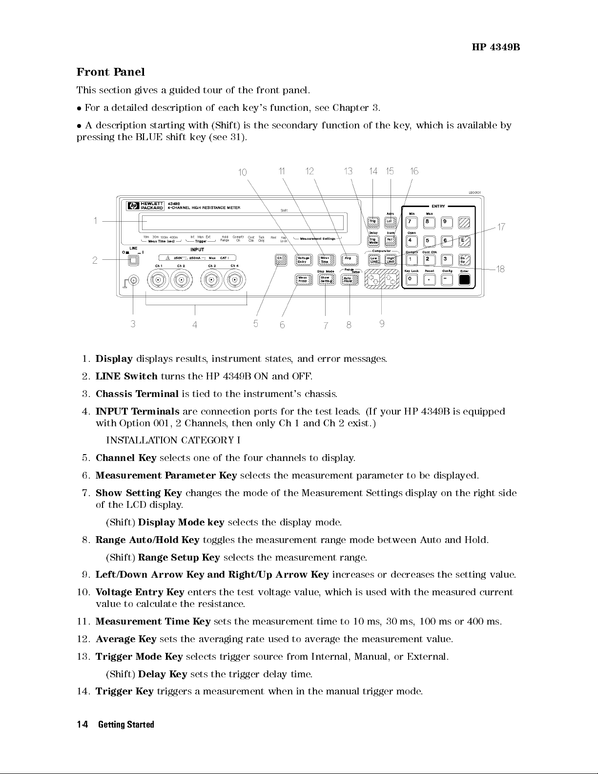
Front Panel
This section gives a guided tour of the front panel.
For a detailed description of each key's function, see Chapter 3.
A description starting with (Shift) is the secondary function of the key, which is available by
pressing the BLUE shift key (see 31).
1.
Display
2.
LINE Switch
3.
Chassis Terminal
4.
INPUT Terminals
displays results, instrument states, and error messages.
turns the HP 4349B ON and OFF.
is tied to the instrument's chassis.
are connection ports for the test leads. (If your HP 4349B is equipped
with Option 001, 2 Channels, then only Ch 1 and Ch 2 exist.)
INSTALLATION CATEGORY I
5.
Channel Key
6.
Measurement Parameter Key
7.
Show Setting Key
selects one of the four channels to display.
selects the measurement parameter to be displayed.
changes the mode of the Measurement Settings display on the right side
of the LCD display.
(Shift)
8.
Range Auto/Hold Key
(Shift)
9.
Left/Down Arrow Key and Right/Up Arrow Key
10.
Voltage Entry Key
Display Mode key
toggles the measurement range mode between Auto and Hold.
Range Setup Key
enters the test voltage value, which is used with the measured current
selects the display mode.
selects the measurement range.
value to calculate the resistance.
11.
Measurement Time Key
12.
Average Key
sets the averaging rate used to average the measurement value.
sets the measurement time to 10 ms, 30 ms, 100 ms or 400 ms.
increases or decreases the setting value.
13.
Trigger Mode Key
(Shift)
14.
Trigger Key
Delay Key
1-4 Getting Started
selects trigger source from Internal, Manual, or External.
sets the trigger delay time.
triggers a measurement when in the manual trigger mode
.
HP 4349B
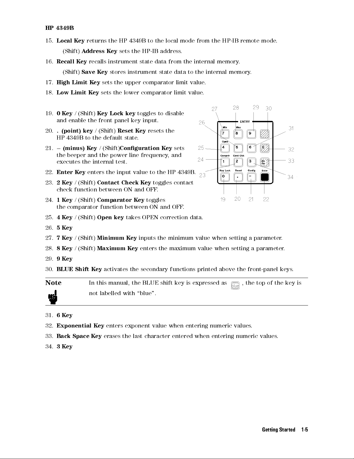
15.
Local Key
returns the HP 4349B to the local mode from the HP-IB remote mode.
(Shift)
16.
Recall Key
(Shift)
17.
High Limit Key
18.
Low Limit Key
19.
0Key
Address Key
sets the HP-IB address.
recalls instrument state data from the internal memory.
Save Key
stores instrument state data to the internal memory.
sets the upper comparator limit value.
sets the lower comparator limit value.
/ (Shift)
Key Lock key
toggles to disable
and enable the front panel key input.
20.
. (point) key
/ (Shift)
Reset Key
resets the
HP 4349B to the default state.
21.0(minus) Key
/ (Shift)
Conguration Key
the beeper and the power line frequency, and
executes the internal test.
22.
Enter Key
23.
2Key
enters the input value to the HP 4349B.
/ (Shift)
Contact Check Key
toggles contact
check function between ON and OFF.
24.
1Key
/ (Shift)
Comparator Key
toggles
the comparator function between ON and OFF.
25.
4Key
/ (Shift)
Open key
takes OPEN correction data.
sets
26.
5Key
27.
7Key
28.
8Key
29.
9Key
30.
BLUE Shift Key
/ (Shift)
/ (Shift)
Note
31.
6Key
32.
Exponential Key
33.
Back Space Key
34.
3Key
Minimum Key
Maximum Key
activates the secondary functions printed above the front-panel keys
inputs the minimum value when setting a parameter.
enters the maximum value when setting a parameter.
.
In this manual, the BLUE shift key is expressed as , the top of the key is
not labelled with \blue".
enters exponent value when entering numeric values.
erases the last character entered when entering numeric values.
Getting Started 1-5

Display
This section introduces the display.For a detailed description of each display eld, see
Chapter 3.
1.
Character Display Area
messages. The
2.
Annunciator(9
Measurement Settings
) points to the currently selected instrument settings. The annunciator
displays the measurement result, setting data, and instrument
area displays the current HP 4349B settings.
labels are as follows:
HP 4349B
a.
Measurement Time
shows the selected measurement time is 10 ms, 30 ms, 100 ms, or
400 ms.
b.
Trigger
c.
Hold Range
shows the trigger mode is Internal, Manual, or External.
indicates that the HP 4349B is in Hold range mode
displayed when in Auto mode.
d.
Comparator On
e.
Contact Check
f.
Talk Only
g.
Remote
h.
Key Lock
i.
Shift
indicates that the shifted key functions are active.
indicates that the HP 4349B is in the HP-IB remote mode
indicates that the HP 4349B's front-panel keys are locked out.
indicates that the comparator function is ON.
indicates that the contact check function is ON.
indicates that the HP 4349B is in the T
. The annunciator is not
alk Only mode.
.
1-6 Getting Started
 Loading...