

HP 41802A 1 M Input Adapter
Operation Note
SERIAL NUMBERS
This manual applies directly to HP 41802As with serial number prex 3103J.For additional
important information about serial numbers, read \Serial Number" in Chapter 1.
ABCDE
HP Part No. 41802-90000
Printed in Japan February, 1999
2nd Edition

c
Copyright 1991,1999 Hewlett-Packard Japan, LTD.
Certication
Hewlett-Packard Company certies that this product met its published specications at the
time of shipment from the factory. Hewlett-Packard further certies that its calibration
measurements are traceable to the United States National Institute for Standards and
Technology, to the extent allowed by the Institution's calibration facility, or to the calibration
facilities of other International Standards Organization members.
Warranty and Assistance
All Hewlett-Packard products are warranted against defects in materials and workmanship.
This warranty applies for one year from the date of delivery,or, in the case of certain
major components listed in the operating manual, for the specied period. We will repair or
replace products which prove to be defective during the warranty period provided they are
returned to Hewlett-Packard. No other warranty is expressed or implied. We are not liable for
consequential damages.
For any assistance, contact your nearest Hewlett-Packard Sales and Service Oce.Addresses
are provided at the back of this manual.
Limitation of Warranty
The foregoing warranty shall not apply to defects resulting from improper or adequate
maintenance by Buyer, Buyer-supplied software or interfacing, unauthorized modication or
misuse, operation outside of the environment specications for the product, or improper site
preparation or maintenance.
No other warranty is expressed or implied. HP specically disclaims the implied warranties
of merchantability and tness for a particular purpose.
iii

Caution
The HP 41802A is sensitive to electrostatic discharge (ESD). The followings
must be adhered to when using the HP 41802A.
Do
NOT
touch the center conductor of the BNC connector of the HP
41802A.
Do
NOT
touch the pin of the probe which is connected to the HP 41802A.
Eliminate ESD on your body.
Eliminate ESD on the work surface.
Do
NOT
introduce ESD into the DUT, while the HP 41802A and the probe is
in use.
iv

Contents
1. General Information
Introduction . . . . . . . . . . . . . . . . . . . . . . . . . . . . . . . . . 1-1
Compatible Equipment . . . . . . . . . . . . . . . . . . . . . . . . . . . . 1-2
Compatible Instruments .......................... 1-2
Compatible Probes . . . . . . . . . . . . . . . . . . . . . . . . . . . . . 1-2
Serial Number . . . . . . . . . . . . . . . . . . . . . . . . . . . . . . . . 1-3
Specications ................................ 1-4
Supplemental Performance Characteristics ...... ...... ...... 1-5
2. Installation
Introduction . . . . . . . . . . . . . . . . . . . . . . . . . . . . . . . . .
Initial Inspection . . . . . . . . . . . . . . . . . . . . . . . . . . . . . . .
Power Requirements . . . . . . . . . . . . . . . . . . . . . . . . . . . . .
Mating Connectors . . . . . . . . . . . . . . . . . . . . . . . . . . . . . .
Environmental Requirements . . . . . . . . . . . . . . . . . . . . . . . . .
3. Operation
Introduction . . . . . . . . . . . . . . . . . . . . . . . . . . . . . . . . .
Operating Precautions ............................
Anti-static Precautions . . . . . . . . . . . . . . . . . . . . . . . . . . .
Maximum Allowable Level . . . . . . . . . . . . . . . . . . . . . . . . .
Discharging the Probe .. ...... ...... ...... ...... .
Probe Power Plug .. ...... ...... ...... ...... ...
Preparation for Use .............................
Operating Check Using a Network Analyzer . . . . . . . . . . . . . . . . .
Using an HP 8751A or HP 3577A/B Network Analyzer . . . . . . . . . . .
Equipment Required . . . . . . . . . . . . . . . . . . . . . . . . . . 3-4
Procedure . . . . . . . . . . . . . . . . . . . . . . . . . . . . . . . 3-4
Using HP 8753A/B/C Network Analyzer . . . . . . . . . . . . . . . . . . 3-5
Equipment Required . . . . . . . . . . . . . . . . . . . . . . . . . . 3-5
Procedure . . . . . . . . . . . . . . . . . . . . . . . . . . . . . . . 3-5
Operating Check Using a Spectrum Analyzer .. ...... ...... ..
Equipment Required . . . . . . . . . . . . . . . . . . . . . . . . . . .
Procedure . . . . . . . . . . . . . . . . . . . . . . . . . . . . . . . .
Operating Check Using a Network/Spectrum Analyzer ............ 3-7
Equipment Required . . . . . . . . . . . . . . . . . . . . . . . . . . .
Procedure . . . . . . . . . . . . . . . . . . . . . . . . . . . . . . . .
Adjusting the Probe ............................
Using a Network Analyzer ...... ...... ...... ..... .
Equipment Required . . . . . . . . . . . . . . . . . . . . . . . . . . 3-8
Procedure . . . . . . . . . . . . . . . . . . . . . . . . . . . . . . . 3-8
Using a Spectrum Analyzer . . . . . . . . . . . . . . . . . . . . . . . .
Equipment Required . . . . . . . . . . . . . . . . . . . . . . . . . .
Procedure . . . . . . . . . . . . . . . . . . . . . . . . . . . . . . .
Typical Measurement Setups .... ...... ...... ...... ...
Network Measurements ..........................
2-1
2-2
2-3
2-3
2-4
3-1
3-2
3-2
3-3
3-3
3-3
3-3
3-4
3-4
3-6
3-6
3-6
3-7
3-7
3-8
3-8
3-10
3-10
3-10
3-11
3-12
Contents-1

Using One HP 41802A .......................... 3-12
Using One HP 41802A with a Transmission/Reection Test Set ....... 3-13
Using Two HP 41802As ......................... 3-14
Spectrum Measurements . . . . . . . . . . . . . . . . . . . . . . . . . . 3-15
Using HP 41802A with instruments which have BNC connectors ....... 3-16
4. Performance Test
Introduction . . . . . . . . . . . . . . . . . . . . . . . . . . . . . . . . . 4-1
Equipment Required . . . . . . . . . . . . . . . . . . . . . . . . . . . . . 4-1
Calibration Cycle .............................. 4-2
Preparation . . . . . . . . . . . . . . . . . . . . . . . . . . . . . . . . . 4-2
Gain Accuracy/Flatness Tests . . . . . . . . . . . . . . . . . . . . . . . . . 4-3
Description ................................ 4-3
Specications ............................... 4-3
Test Equipment .............................. 4-3
Procedure . . . . . . . . . . . . . . . . . . . . . . . . . . . . . . . . . 4-3
Performance Test Record . . . . . . . . . . . . . . . . . . . . . . . . . . . 4-6
Gain Accuracy/Flatness Tests . . . . . . . . . . . . . . . . . . . . . . . . 4-6
5. Adjustment
Introduction . . . . . . . . . . . . . . . . . . . . . . . . . . . . . . . . .
Equipment Required . . . . . . . . . . . . . . . . . . . . . . . . . . . . .
Preparation . . . . . . . . . . . . . . . . . . . . . . . . . . . . . . . . .
Gain Adjustment . . . . . . . . . . . . . . . . . . . . . . . . . . . . . . .
Description ................................
Equipment ................................
Procedure . . . . . . . . . . . . . . . . . . . . . . . . . . . . . . . . .
5-1
5-1
5-1
5-2
5-2
5-2
5-2
6. Replaceable Parts
Replaceable Parts Lists . . . . . . . . . . . . . . . . . . . . . . . . . . . .
A. Manual Changes
Introduction . . . . . . . . . . . . . . . . . . . . . . . . . . . . . . . . .
Manual Changes . . . . . . . . . . . . . . . . . . . . . . . . . . . . . . .
6-1
A-1
A-1
Contents-2
Figures
1-1. Serial Number Plate .... ...... ...... ...... ...... 1-3
1-2. Specications ........ ...... ...... ...... ..... 1-4
1-3. Supplemental Characteristics . . . . . . . . . . . . . . . . . . . . . . . . 1-5
2-1. Product Overview . . . . . . . . . . . . . . . . . . . . . . . . . . . . . 2-2
2-2. Probe Power Requirements . . . . . . . . . . . . . . . . . . . . . . . . . 2-3
3-1. Operating Check Setup Using HP 8751A or HP 3577A/B Network Analyzer .. 3-4
3-2. Operating Check Setup Using HP 8753A/B/C Network Analyzer . . . . . . . . 3-5
3-3. Operating Check Setup Using Spectrum Analyzer ........ ...... 3-6
3-4. Operating Check Setup Using Network/Spectrum Analyzer . . . . . . . . . . 3-7
3-5. Probe Adjustment Setup Using a Network Analyzer|1 . . . . . . . . . . . . 3-8
3-6. Probe Adjustment Setup Using a Network Analyzer|2 . . . . . . . . . . . . 3-9
3-7. Probe Adjustment Setup Using Spectrum Analyzer . . . . . . . . . . . . . .
3-8. Network Measurement Setup Example (Using One HP 41802A) . . . . . . . .
3-9. Network Measurement Setup Example (Using with a Transmission/Reection Set)
3-10. Network Measurement Setup Example (Using Two HP 41802As) ....... 3-14
3-11. Spectrum Measurement Setup Example . . . . . . . . . . . . . . . . . . .
3-12. Measurement Setup Example (BNC input connector) . . . . . . . . . . . . .
4-1. Test Setup 1 . . . . . . . . . . . . . . . . . . . . . . . . . . . . . . . .
4-2. Test Setup 2 . . . . . . . . . . . . . . . . . . . . . . . . . . . . . . . .
5-1. Adjustment Setup 1 ............................
5-2. Adjustment Setup 2 ............................
5-3. Adjustment Setup 3 ............................
6-1. Replaceable Parts (1 of 2) .........................
6-2. Replaceable Parts (2 of 2) .........................
3-10
3-12
3-13
3-15
3-16
4-3
4-4
5-2
5-3
5-4
6-2
6-4
Tables
2-1. Probe Power Requirements . . . . . . . . . . . . . . . . . . . . . . . . . 2-3
3-1. Anti-static Products Available .......................
4-1. Recommended Test Equipment . . . . . . . . . . . . . . . . . . . . . . .
6-1. Component Manufactures ...... ...... ...... ...... .
6-2. Replaceable Parts (2 of 2) .........................
6-3. Replaceable Parts (2 of 2) .........................
A-1. Manual Changes by Serial Number .....................
3-2
4-1
6-1
6-3
6-4
A-1
Contents-3

1
General Information
Introduction
The HP 41802A 1 M Input Adapter is used with high impedance passive probes for circuit
signal analysis using network and spectrum analyzers.
This is an operation note for the HP 41802A, containing information on installation, operation,
and service in the following chapters.
Chapter 1, General Information
Provides the specications and the information necessary for preparing the HP 41802A for
use.
Chapter 2, Installation
Provides the installation information, including initial inspection, power requirements
mating connectors, and environmental requirements.
Chapter 3, Operation
Provides the information for preparation and typical measurement setups
on use.
Chapter 4, Performance Test
Provides performance test procedures to ensure that the HP 41802A is within specications
Chapter 5, Adjustment
Provides the adjustment procedure to bring it within specications
the performance test or it has been repaired.
Chapter 6, Replaceable Parts
Provides the replaceable parts information to service the HP 41802A.
, if the HP 41802A failed
, including cautions
,
.
General Information 1-1
Compatible Equipment
Compatible Instruments
Instruments compatible with the HP 41802A are network and spectrum analyzers which meet
the following conditions.
Measurement frequency range includes 5 Hz to 100 MHz.
Input resistance is 50 .
Probe power supplies are furnished.
The following HP network and spectrum analyzers are compatible with the HP 41802A.
Network Analyzers: HP 8751A, HP 8753A/B/C, HP 3577A/B
Spectrum Analyzers: HP 3585A/B, HP 8568B
Network/Spectrum Analyzer: HP 4195A
If the instrument does not have a probe power supply, use a separate power supply which
meets the requirements described in \Power Requirements" in Chapter 2.
Compatible Probes
Compatible probes with the HP 41802A are high impedance passive probes which meet the
following conditions.
Input resistance is 1 M.
Compensates oscilloscope input capacitance includes 12 pF.
The following HP Oscilloscope Probes are compatible with the HP 41802A.
HP 10432A, HP 10433A, HP 10435A, HP 10440A
HP 10017A, HP 10018A, HP 10080A, HP 10081A
Refer to \Adjusting the Probe" in Chapter 3 how to adjust the probe which is connected to a
network analyzer or a spectrum analyzer.
1-2 General Information
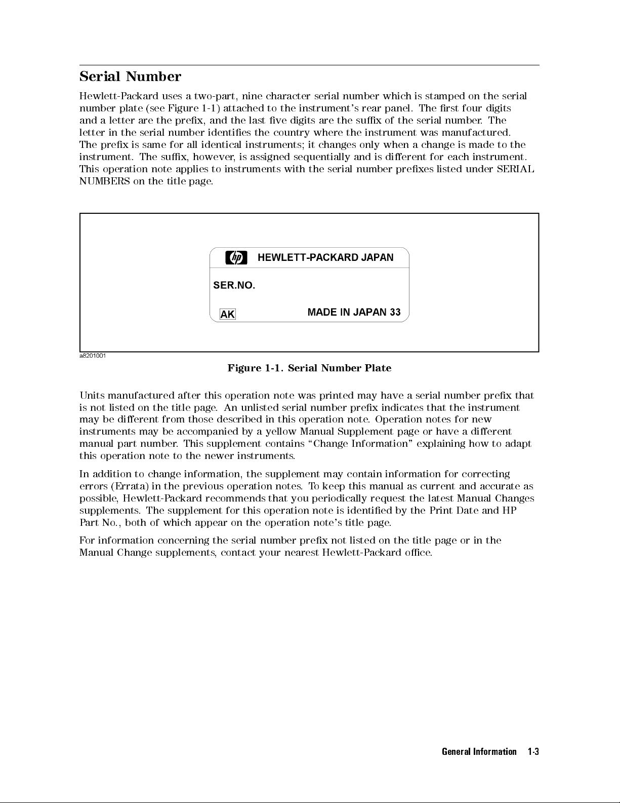
Serial Number
Hewlett-Packard uses a two-part, nine character serial number which is stamped on the serial
number plate (see Figure 1-1 ) attached to the instrument's rear panel. The rst four digits
and a letter are the prex, and the last ve digits are the sux of the serial number. The
letter in the serial number identies the country where the instrument was manufactured.
The prex is same for all identical instruments; it changes only when a change is made to the
instrument. The sux, however, is assigned sequentially and is dierent for each instrument.
This operation note applies to instruments with the serial number prexes listed under SERIAL
NUMBERS on the title page.
Figure 1-1. Serial Number Plate
Units manufactured after this operation note was printed may have a serial number prex that
is not listed on the title page. An unlisted serial number prex indicates that the instrument
may be dierent from those described in this operation note
instruments may be accompanied by a yellow Manual Supplement page or have a dierent
manual part number. This supplement contains \Change Information" explaining how to adapt
this operation note to the newer instruments.
In addition to change information, the supplement may contain information for correcting
errors (Errata) in the previous operation notes.To keep this manual as current and accurate as
possible, Hewlett-Packard recommends that you periodically request the latest Manual Changes
supplements. The supplement for this operation note is identied by the Print Date and HP
Part No., both of which appear on the operation note's title page.
For information concerning the serial number prex not listed on the title page or in the
Manual Change supplements, contact your nearest Hewlett-Packard oce.
. Operation notes for new
General Information 1-3
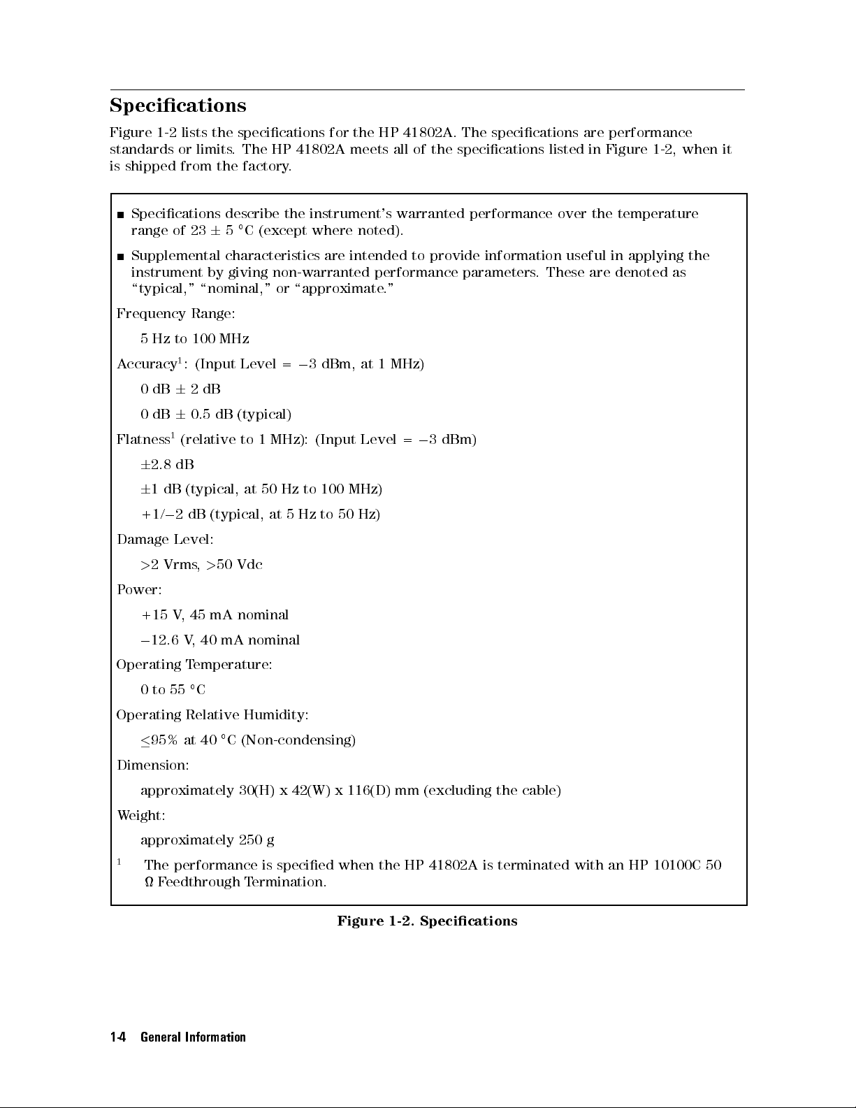
Specications
Figure 1-2 lists the specications for the HP 41802A. The specications are performance
standards or limits. The HP 41802A meets all of the specications listed in Figure 1-2, when it
is shipped from the factory.
Specications describe the instrument's warranted performance over the temperature
range of 2365C (except where noted).
Supplemental characteristics are intended to provide information useful in applying the
instrument by giving non-warranted performance parameters. These are denoted as
\typical," \nominal," or \approximate."
Frequency Range:
5 Hz to 100 MHz
Accuracy1: (Input Level =03 dBm, at 1 MHz)
0dB62dB
0dB60.5 dB (typical)
Flatness1(relative to 1 MHz): (Input Level =03 dBm)
6
2.8 dB
6
1 dB (typical, at 50 Hz to 100 MHz)
+1/02 dB (typical, at 5 Hz to 50 Hz)
Damage Level:
>
2 Vrms,>50 Vdc
Power:
+15 V, 45 mA nominal
0
12.6 V, 40 mA nominal
Operating Temperature:
0to55C
Operating Relative Humidity:
95% at 40C (Non-condensing)
Dimension:
approximately 30(H) x 42(W) x 116(D) mm (excluding the cable)
Weight:
approximately 250 g
1
The performance is specied when the HP 41802A is terminated with an HP 10100C 50
Feedthrough Termination.
1-4 General Information
Figure 1-2. Specications
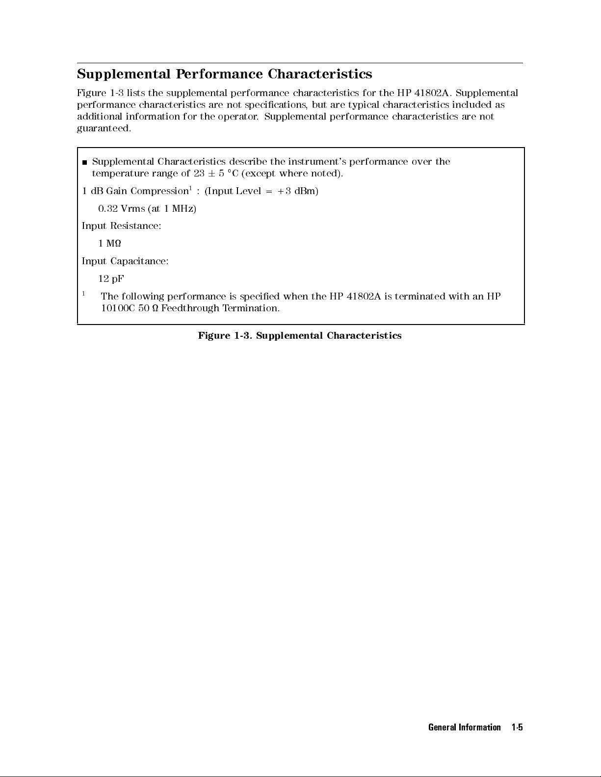
Supplemental Performance Characteristics
Figure 1-3 lists the supplemental performance characteristics for the HP 41802A. Supplemental
performance characteristics are not specications, but are typical characteristics included as
additional information for the operator. Supplemental performance characteristics are not
guaranteed.
Supplemental Characteristics describe the instrument's performance over the
temperature range of 2365C (except where noted).
1 dB Gain Compression1: (Input Level = +3 dBm)
0.32 Vrms (at 1 MHz)
Input Resistance:
1M
Input Capacitance:
12 pF
1
The following performance is specied when the HP 41802A is terminated with an HP
10100C 50 Feedthrough Termination.
Figure 1-3. Supplemental Characteristics
General Information 1-5

Installation
Introduction
This chapter contains the following information.
Initial inspection
Power Requirements
Mating connector
Environmental requirements
2
Installation 2-1
 Loading...