


Agilent 34410A and 34411A Multimeters
Setting the Standard for Next Generation
Benchtop and System Testing
Product Overview
Agilent 34410A 61/2-Digit
High-Performance DMM
• 10,000 readings/s @ 5
1
/2-digits
direct to PC
• 1,000 readings/s @ 6
1
/2-digits
direct to PC
• 30 PPM 1-year Basic DC accuracy
• LAN, USB & GPIB standard
• DCV, ACV, DCI, ACI, 2-wire and
4-wire Resistance, Frequency,
Period, Continuity, and Diode Test
• Capacitance & Temperature
measurements
• Expanded measurement ranges
• Data logger with 50 k reading
non-volatile memory
Agilent 34411A 6
1
/2-Digit
Enhanced-Performance DMM
All the features of the 34410A, plus:
• 50,000 readings/s @
4
1
/2-digits direct to PC
• 1 million volatile reading memory
• Analog level triggering
• Programmable Pre/Post triggering
The Best Just Got Better
The Agilent 34410A and
34411A 6
1
/2-Digit DMMs represent
the latest generation of multimeters
from Agilent Technologies. Building
on the phenomenal success of the
industry-standard Agilent 34401A,
these new meters offer improved
accuracy, expanded measurement
capability, dramatically improved
measurement speed and throughput,
and modern computer interfaces
including LAN and USB. The dual
display offers both dual measurement capabilities and ease of use
when setting up and configuring
the DMM. Improvements have been
made in every facet of the 34401A
to make the best even better,
whether you use it on the bench
or in a system.
Dramatic Speed Improvements
Whether it’s raw reading speed
or fast system throughput, the
34410A sets a new benchmark in
performance. Using a new A/D
technology, the 34410A achieves
an impressive 10,000 readings a
second at 5
1
/2-digits, and can stream
readings to your computer at this
same speed! Triggering is fast and
precise, with both trigger latency
and trigger jitter less than 1 µs,
while bus query response is less
than 500 µs. ACV measurements are
faster as well thanks to a digital
measurement technique that additionally improves accuracy at high
and low frequencies. For even
greater reading speeds, select the
34411A, which achieves 50,000
readings a second at 4
1
/2-digits.
Enhanced Measurement Performance
The 34410A and 34411A offer
Temperature and Capacitance
capabilities, in addition to those
measurements you have come to
expect, such as DCV, ACV, DCI,
ACI, 2-wire and 4-wire Resistance,
Frequency, Period, Continuity and
Diode Test. You also get Offset
Compensated Ohms, allowing you to
accurately measure resistance in the
presence of voltages. Measurement
ranges have been expanded as well;
for example, DC and AC Current
Ranges now go down to 100 µA,
resulting in 100 pA resolution.
Real-time math and statistics
are included, and a peak-detect
capability allows you to capture
peaks as short as 20 µ s.
Even Greater Performance
with the 34411A
The 34411A has all the features
of the 34410A, plus additional
performance that makes it even
more powerful. With the ability to
make 50,000 readings per second at
4
1
/2-digits, Analog Level Triggering,
programmable Pre- and Post- Trigger
and 1 million readings of volatile
memory in addition to 50,000
reading of non-volatile memory,
you now have the ability to capture
low-frequency waveforms, characterize device performance and
transfer results for analysis on
your computer.
Data Logger Function
A front panel data logger function
allows you to set the meter up to
make unattended, paced measurements over a fixed time or number
of events, then pull up the results
later for review or transfer to a
computer for analysis. Set the
meter up to take measurements
every 10 seconds for an hour, go
have lunch, and check the results
upon your return. The contextual
front panel sequences make setup
and read back a breeze.
Improved Ease of Use
From the inclusion of a second
display to configuring setups for
each of the measurement functions,
these new DMMs offer significant
improvements in usability. Simple
things are simple; more complicated
setups are easier than ever. There
is even a new probe set designed to
more easily probe today’s fine-pitch
components. Finally, there is a
built-in Graphical Web Interface
that allows you to interactively
control the DMM without the
hassle of programming at all!
Modern I/O for Improved Connectivity
When connecting to a computer,
select LAN, USB or GPIB interfaces; all three are standard on the
34410A and 34411A. Concerned
about the viability of your existing
software programs? These new DMMs
respond to Standard Commands
for Programmable Instrumentation
(SCPI), and there is even a 34401A
Emulation Mode to ensure the
easiest upgrade possible. Agilent’s
I/O Library Suite ships with the
34410A and 34411A to help you
quickly establish an error-free
connection between your PC and
instrument. It provides robust
instrument control and works
with the software development
environment you choose.
LXI - Class C
LAN Extensions for Instruments (LXI)
provides the next generation I/O
for system applications requiring
the highest throughput. Transfer
rates of over 250,000 readings/s are
attainable ensuring even the most
data intensive measurements are
fast, without the overhead cost
of an instrument cardcage. Both
the 34410A and the 34411A are
LXI - Class C compliant.
Built To Last
Our new DMMs were designed
to high standards of ruggedness
and reliability. From the robust
package with its shock absorbing
bumpers to careful selection of
components and conservative
circuit design, these meters are
built to last. Calculated Mean
Time Between Failure (MTBF) is in
excess of 100,000 hours. Backed by
a 1-year warranty and a worldwide
network of service centers, you can
buy with confidence.
Go to the Web
For the latest information on
these or other Agilent DMMs,
go to www.agilent.com/find/dmm
Accessories Included:
• Test Lead Kit with probes
and SMT attachments.
• Test report, power cord,
and USB interface cable.
Product Reference CD-ROM with
soft documentation and software:
• Programmer’s Reference Help
• Quick Start Tutorial
• User’s Guide
• Service Guide
• Programming Examples
• IntuiLink for Multimeters
• LabVIEW and IVI-COM drivers
Optional Printed Documentation:
• Quick Start Tutorial
• User’s Guide
• Service Guide
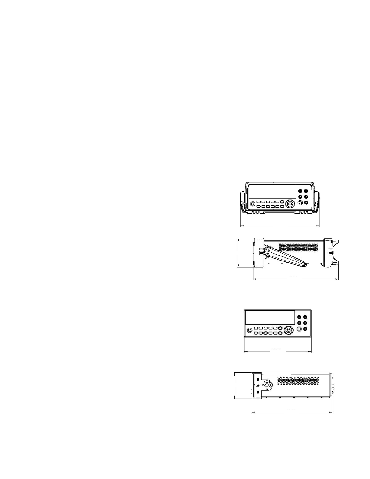
Bench Dimensions:
System Dimensions:
2
261.2 mm
103.8 mm
88.3 mm
303.2 mm
212.8 mm
272.3 mm

3
Accuracy Specifications ± (% of reading + % of range)
1
Function Range
3
Frequency, 24 Hour
2
90 Day 1 Year
Temperature Coefficient/°C
Test Current or Tcal ±1°C Tcal ±5°C Tcal ±5°C 0°C to (Tcal -5°C)
Burden Voltage (Tcal +5°C) to 55°C
DC Voltage 100.0000 mV 0.0030 + 0.0030 0.0040 + 0.0035 0.0050 + 0.0035 0.0005 + 0.0005
1.000000 V 0.0020 + 0.0006 0.0030 + 0.0007 0.0035 + 0.0007 0.0005 + 0.0001
10.00000 V 0.0015 + 0.0004 0.0020 + 0.0005 0.0030 + 0.0005 0.0005 + 0.0001
100.0000 V 0.0020 + 0.0006 0.0035 + 0.0006 0.0040 + 0.0006 0.0005 + 0.0001
1000.000 V
4
0.0020 + 0.0006 0.0035 + 0.0006 0.0040 + 0.0006 0.0005 + 0.0001
True RMS 100.0000 mV 3 Hz – 5 Hz 0.50 + 0.02 0.50 + 0.03 0.50 + 0.03 0.010 + 0.003
AC Voltage
5
to 750.000 V 5 Hz – 10 Hz 0.10 + 0.02 0.10 + 0.03 0.10 + 0.03 0.008 + 0.003
10 Hz – 20 kHz 0.02 + 0.02 0.05 + 0.03 0.06 + 0.03 0.005 + 0.003
20 kHz – 50 kHz 0.05 + 0.04 0.09 + 0.05 0.10 + 0.05 0.010 + 0.005
50 kHz – 100 kHz 0.20 + 0.08 0.30 + 0.08 0.40 + 0.08 0.020 + 0.008
100 kHz – 300 kHz 1.00 + 0.50 1.20 + 0.50 1.20 + 0.50 0.120 + 0.020
Resistance
6
100.0000
Ω
1 mA 0.0030 + 0.0030 0.008 + 0.004 0.010 + 0.004 0.0006 + 0.0005
1.000000 k
Ω
1 mA 0.0020 + 0.0005 0.007 + 0.001 0.010 + 0.001 0.0006 + 0.0001
10.00000 k
Ω
100 µA 0.0020 + 0.0005 0.007 + 0.001 0.010 + 0.001 0.0006 + 0.0001
100.0000 k
Ω
10 µA 0.0020 + 0.0005 0.007 + 0.001 0.010 + 0.001 0.0006 + 0.0001
1.000000 M
Ω
5 µA 0.0020 + 0.0010 0.010 + 0.001 0.012 + 0.001 0.0010 + 0.0002
10.00000 M
Ω
500 nA 0.0100 + 0.0010 0.030 + 0.001 0.040 + 0.001 0.0030 + 0.0004
100.0000 M
Ω
500 nA || 10 MΩ0.200 + 0.001 0.600 + 0.001 0.800 + 0.001 0.1000 + 0.0001
1.000000 G
Ω
500 nA || 10 MΩ2.000 + 0.001 6.000 + 0.001 8.000 + 0.001 1.0000 + 0.0001
DC Current 100.0000 µA < 0.03 V 0.010 + 0.020 0.040 + 0.025 0.050 + 0.025 0.0020 + 0.0030
1.000000 mA < 0.3 V 0.007 + 0.006 0.030 + 0.006 0.050 + 0.006 0.0020 + 0.0005
10.00000 mA < 0.03 V 0.007 + 0.020 0.030 + 0.020 0.050 + 0.020 0.0020 + 0.0020
100.0000 mA < 0.3 V 0.010 + 0.004 0.030 + 0.005 0.050 + 0.005 0.0020 + 0.0005
1.000000 A < 0.8 V 0.050 + 0.006 0.080 + 0.010 0.100 + 0.010 0.0050 + 0.0010
3.000000 A < 2.0 V 0.100 + 0.020 0.120 + 0.020 0.150 + 0.020 0.0050 + 0.0020
True RMS 100.0000 µA to 3 Hz – 5 kHz 0.10 + 0.04 0.10 + 0.04 0.10 + 0.04 0.015 + 0.006
AC Current
7
3.00000 A 5 kHz – 10 kHz 0.20 + 0.04 0.20 + 0.04 0.20 + 0.04 0.030 + 0.006
Frequency 100 mV to 3 Hz – 5 Hz 0.070 + 0.000 0.070 + 0.000 0.070 + 0.000 0.005 + 0.000
or Period 750 V 5 Hz – 10 Hz 0.040 + 0.000 0.040 + 0.000 0.040 + 0.000 0.005 + 0.000
10 Hz – 40 Hz 0.020 + 0.000 0.020 + 0.000 0.020 + 0.000 0.001 + 0.000
40 Hz – 300 kHz 0.005 + 0.000 0.006 + 0.000 0.007 + 0.000 0.001 + 0.000
Capacitance
8
1.0000 nF 500 nA 0.50 + 0.50 0.50 + 0.50 0.50 + 0.50 0.05 + 0.05
10.000 nF 1 µA 0.40 + 0.10 0.40 + 0.10 0.40 + 0.10 0.05 + 0.01
100.00 nF 10 µA 0.40 + 0.10 0.40 + 0.10 0.40 + 0.10 0.01 + 0.01
1.0000 µF 10 µA 0.40 + 0.10 0.40 + 0.10 0.40 + 0.10 0.01 + 0.01
10.000 µF 100 µA 0.40 + 0.10 0.40 + 0.10 0.40 + 0.10 0.01 + 0.01
Temperature
9
RTD
-200°C to 600°C 0.06°C 0.06°C 0.06°C 0.003°C
Thermistor -80°C to 150°C 0.08°C 0.08°C 0.08°C 0.002°C
Continuity 1000.0
Ω
1 mA 0.002 + 0.010 0.008 + 0.020 0.010 + 0.020 0.0010 + 0.0020
Diode Test
10
1.0000 V 1 mA 0.002 + 0.010 0.008 + 0.020 0.010 + 0.020 0.0010 + 0.0020
1
Specifications are for 90 minute warm-up and 100 PLC..
2
Relative to calibration standards..
3
20% overrange on all ranges, except DCV 1000 V, ACV 750 V, DCI and ACI 3 A ranges.
4
For each additional volt over ± 500 V add 0.02 mV of error.
5
Specifications are for sinewave input > 0.3% of range and > 1 mVrms. Add 30 uV error for frequencies below 1 kHz.
750 VAC range limited to 8 x 10
7
Volts-Hz. For each additional volt over 300 Vrms add 0.7 mVrms of error.
6
Specifications are for 4-wire resistance measurements, or 2-wire using Math Null.
Without Math Null, add 0.2
Ω
additional error in 2-wire resistance measurements.
7
Specifications are for sinewave input > 1% of range and > 10 µArms. Frequencies > 5 kHz are typical
for 1 A and 3 A ranges.
8
Specifications are for 1-hour warm-up using Math Null. Additional errors may occur for non-film capacitors.
9
For total measurement accuracy, add temperature probe error.
10
Accuracy specifications are for the voltage measured at the input terminals only. 1 mA test current is typical.
Variation in the current source will create some variation in the voltage drop across a diode junction.
4
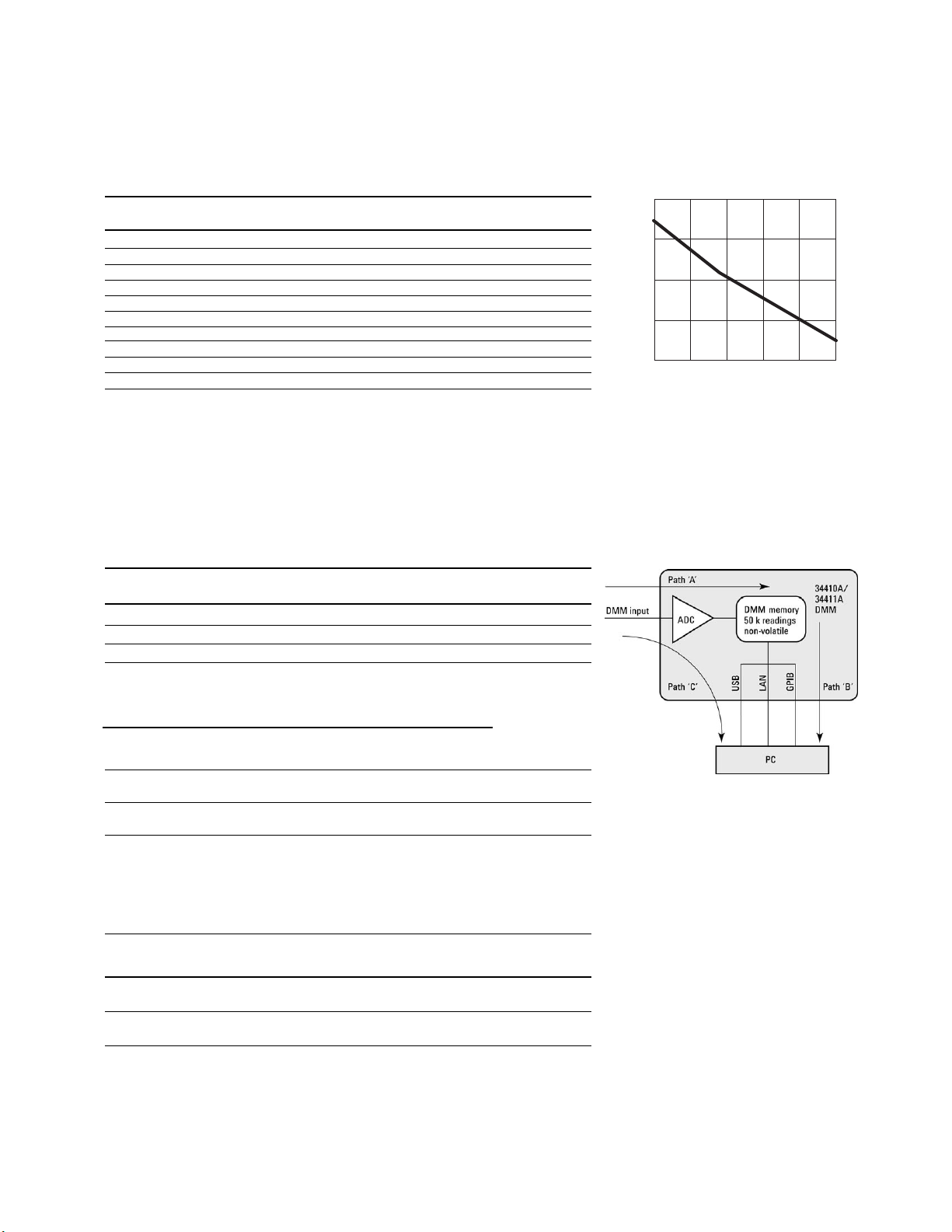
A-to-D Converter Noise Performance
Integration Time Resolution Normal Mode Readings/Second
4
(NPLC) (ppm of range)
1
Rejection (dB)
2
0.001
5
30 0 50,000
0.002
5
15 0 25,000
0.006 6 0 10,000
0.02 3 0 3,000
0.06 1.5 0 1,000
0.2 0.7 0 300
1 0.3 55 60 (50)
2 0.2 110
3
30 (25)
10 0.1 110
3
6 (5)
100 0.03 110
3
0.6 (0.5)
1
Resolution is defined as the typical DCV 10 V range RMS noise.
Auto-zero on for NPLC
≥
1. See manual for additional noise characteristics.
2
Normal mode rejection for power line frequency ± 0.1%.
3
For power-line frequency ± 1% 75 dB and for ± 3% 55 dB.
4
Maximum rate with auto-zero off for 60 Hz and (50 Hz) operation.
5
Only available for the 34411A.
System Reading and Throughput Rates
DMM memory to PC (Maximum reading rate out of memory)
1
Drawing – Path B
Reading GPIB USB 2.0 LAN (VXI-11) LAN (Sockets)
Format Readings/s Readings/s Readings/s Readings/s
ASCII 4,000 8,500 7,000 8,500
32-bit Binary 89,000 265,000 110,000 270,000
64-bit Binary 47,000 154,000 60,000 160,000
Direct I/O Measurements (Single reading – measure and I/O time)
1
Maximum Reading
Drawing – Path C
Rate into Memory
Function Resolution GPIB USB 2.0
LAN
LAN
or to Direct I/O
(NPLC) ms ms
(VXI-11)
(Sockets)
(Readings/s)
ms ms
Drawing – Path A or C
DCV/2-wire 0.006 (0.001) 2.6 2.9 4.6 3.2 10,000 (50,000)
Resistance
ACV/ Fast Filter 10.0 10.0 10.0 10.0 500
Frequency 1 ms Gate
1
1/2 scale input signal, immediate trigger, trigger delay 0, auto-zero off, auto-range off, no math, null off,
60 Hz line frequency. Specifications are for 34410A or (34411A). See manual for performance on other functions.
System Performance
Function Range Auto- Maximum Maximum Internal
Change (ms)
1
Change
(ms)2range (ms)3External Trigger Rate
4
LAN/GPIB
Trigger Rate
DCV/2-wire 22 3.9/2.6 7.5 5,000/s 10,000/s
Resistance (50,000/s)
ACV/ 37 6.5/6.4 19 500/s 500/s
Frequency
1
Time to change from 2-wire Resistance to this specified function,
or DCV to 2-wire Resistance using the SCPI “FUNC” command.
2
Time to change from one range to the next higher range, ≤ 10 V, ≤ 10 MΩ.
3
Time to automatically change one range and be ready for the new measurement, ≤ 10 V, ≤ 10 MΩ.
4
Specifications are for 34410A or (34411A).
100
10
1
0.1
0.01
0.001 0.01 0.1 1 10 100
RMS Noise (ppm of range)
Integration Time (NPLC)
System Reading Architecture

DC Voltage
Measurement Method:
Continuously integrating
multi-slope IV A/D converter
Linearity: 0.0002% of reading
(10 V range) + 0.0001% of range
Input Resistance:
0.1 V, 1 V, 10 V 10 MΩ or > 10 GΩ
Ranges (Selectable)
100 V, 1000 V 10 MΩ ±1%
Ranges (Fixed)
Input Bias Current:
< 50 pA at 25°C
Input Protection: 1000 V
DC CMRR: 140 dB
1
True RMS AC Voltage
Measurement Method:
AC-coupled True RMS measurement.
Digital sampling with anti-alias filter.
Crest Factor:
No additional error for crest factors < 10.
Limited by peak input and 300 kHz bandwidth.
Peak Input:
300% of range or 1100 V
Overload Ranging:
Will select higher range if peak input
overload is detected during auto range.
Overload is reported in manual ranging.
AC CMR: 70 dB
2
Maximum Input: 400 Vdc, 1100 Vpk
Input Impedance:
1 MΩ ± 2% in parallel with < 150 pF
Input Protection: 750 Vrms all ranges
Resistance
Measurement Method:
Selectable 2-wire or 4-wire.
Current source referenced to LO input.
Offset Compensation:
Selectable on the 100 Ω, 1 kΩ,
and 10 kΩ ranges
Max. Lead Resistance (4-wire):
10% of range per lead for 100 Ω, 1 kΩ.
1 kΩ per lead on all other ranges
Input Protection:
1000 V on all ranges
DC Current
Current Shunt:
200 Ω for 100 µA, 1 mA
2 Ω for 10 mA, 100 mA
0.1 Ω for 1 A, 3 A
Input Protection: 3 A, 250 V fuse
True RMS AC Current
Measurement Method:
AC-coupled True RMS measurement.
Directly coupled to the fuse and shunt.
Digital sampling with anti-alias filter.
Current Shunt:
200 Ω for 100 µA, 1 mA
2 Ω for 10 mA, 100 mA
0.1 Ω for 1 A, 3 A
Maximum Input:
The peak value of the DC + AC current must
be <300% of range. The RMS current must be
<3 A including the DC current content.
Input Protection: 3 A, 250 V fuse
Frequency and Period
Measurement Method:
Reciprocal-counting technique. AC-coupled input
using the AC voltage measurement function.
Input Impedance:
1 MΩ ± 2% in parallel with < 150 pF
Input Protection: 750 Vrms all ranges
Capacitance
Measurement Method:
Current input with measurement of
resulting ramp.
Connection Type: 2-wire
Temperature
Thermistor:
2.2 kΩ, 5 kΩ, and 10 kΩ
RTD: α = 0.00385
Rofrom 49 Ω to 2.1 kΩ
Continuity/Diode Test
Response Time:
300 samples/sec with audible tone
Continuity Threshold: Fixed at 10 Ω
Operating Characteristics
Maximum readings/second
Digits
Function34.5 5.5 6.5
DCV 50 k
4
10 k 1 k
2-wire
Ω
50 k
4
10 k 1 k
DCI 50 k
4
10 k 1 k
Frequency 500 90 10
Period 500 90 10
Filter setting fast med slow
ACV 500 150 50
ACI 500 150 50
Additional 34411A Specifications
Resolution: See table on page 4
Overall Bandwidth, DCV & DCI:
15 kHz typical @ 20 µs aperture (-3 dB)
Triggering: Pre/Post, Int/Ext, Pos/Neg
Timebase Resolution: 19.9524 µs 0.01% accuracy
Trigger Jitter:
2 µs (p-p), 20 µs (p-p) when pre-triggered
Spurious-Free Dynamic Range
& Signal to Noise Distortion Ratio
Function DCV Range Spur-Free SNDR
1 V -75 dB 60 dB
10 V
1
-70 dB 60 dB
100 V -75 dB 60 dB
1
10 V range: 2 V (p-p) <signal < 16 V (p-p)
Triggering and Memory
Reading Hold Sensitivity:
1% of reading
Samples per Trigger:
1 to 50,000 (34410A)
1 to 1,000,000 (34411A)
Trigger Delay: 0 to 3600 s (20 µs step size)
External Trigger:
Programmable edge, Low-power TTL compatible
Delay: < 1 µs Max rate: 5,000/s
Jitter: < 1 µs Min Pulsewidth:
1 µs
Voltmeter Complete:
3 V Logic output,
2 µs pulse with programmable edge
Nonvolatile Memory: 50,000 readings
Volatile Memory:
50,000 readings (34410A)
1,000,000 readings (34411A)
Sample Timer:
Range: 0 to 3600 s (20 µs step sizes)
Jitter: < 100 ns
General Specifications
Power Supply:
100 V/120 V/220 V/240 V ±10%
Power Line Frequency:
45 Hz to 66 Hz and 360 Hz to 440 Hz,
Automatically sensed at power-on
Power Consumption: 25 VA peak (16 W average)
Operating Environment: Full accuracy for
0°C to 55°C, 80% R.H. at 40°C non-condensing
Storage Temperature: -40°C to 70°C
Weight: 3.72 kg (8.2 lbs)
Safety: IEC 61010-1, EN 61010-1, UL 61010-1,
CAN/CSA-C22.2 No. 61010-1, Refer to
Declarations of Conformity for current
revisions. Measurement CAT II 300 V,
CAT I 1000 V. Pollution Degree 2
EMC: IEC 61326, EN 61326, CISPR 11, ICES-001,
AS/NZS 2064.1, Refer to Declaration of
Conformity for current revisions.
Vibration & Shock: MIL-T-28800E,
Type III, Class 5 (Sine Only)
LXI Compliance: LXI Class C, ver. 1.0
Warranty: 1 year
5
Measurement Characteristics
1
For 1 kΩ unbalanced in LO lead, ± 500 V peak maximum
2
For 1 kΩ unbalanced in LO lead and <60 Hz, ± 500 V peak maximum
3
Maximum rate for DCV, DCI, and resistance functions
(using zero settling delay, autozero off, manual range)
4
34411A only
Ordering Information
Agilent 34410A and
34411A Multimeters
Accessories included
Test Lead Kit with probes and
SMT attachments, test report,
power cord, and USB interface cable.
PPrroodduucc tt RReeffeerreennccee CCDD--RROOMM wwiitthh
ssoofftt ddooccuummeenntt aattiioonn aann dd ssooffttwwaarree::
• Programmer’s Reference Help
• Quick Start Tutorial
• User’s Guide
• Service Guide
• Programming Examples
• IntuiLink for Multimeters
• LabVIEW and IVI-COM drivers
Options
OOpp tt.. 11CCMM
Rack Mount Kit
OOpptt.. AABBAA
Printed Manual Set (English)
OOpptt.. 00BB00
Delete printed Manual Set (full
documentation included on CD ROM)
OOpp tt.. AA66JJ
ANSI Z540 compliant calibration
Agilent Accessories
1111005599AA
Kelvin Probe set
1111006600AA
Surface Mount Device
(SMD) test probes
1111006622AA
Kelvin clip set
3344113311AA
Hard transit case
3344116622AA
Accessory pouch
3344117711AA//BB
Input terminal connector
(sold in pairs)
3344117722AA//BB
Input calibration short
(sold in pairs)
3344333300AA
30 A current shunt
EE22330088AA
5 kΩ thermistor probe
* For racking two side-by-side,
order both items below:
Lock link kit (P/N 5061-9694)
Flange kit (P/N 5063-9212)
Remove all doubt
Our repair and calibration services will get
your equipment back to you, performing
like new, when promised. You will get full
value out of your Agilent equipment
throughout its lifetime. Your equipment will
be serviced by Agilent-trained technicians
using the latest factory calibration procedures, automated repair diagnostics and
genuine parts. You will always have the
utmost confidence in your measurements.
Agilent offers a wide range of additional
expert test and measurement services for
your equipment, including initial start-up
assistance onsite education and training,
as well as design, system integration, and
project management.
For more information on repair and calibration services, go to
www.agilent.com/find/removealldoubt
www.agilent.com/find/emailupdates
Get the latest information on the products
and applications you select.
www.agilent.com/find/quick
Quickly choose and use your test equipment
solutions with confidence.
www.agilent.com/find/open
Agilent Open simplifies the process of
connecting and programming test systems
to help engineers design, validate and
manufacture electronic products. Agilent
offers open connectivity for a broad range
of system-ready instruments, open industry
software, PC-standard I/O and global support, which are combined to more easily
integrate test system development.
www.lxistandard.org
LXI is the LAN-based successor to GPIB,
providing faster, more efficient connectivity.
Agilent is a founding member of the LXI
consortium.
Agilent
Open
Agilent Direct
Agilent Email Updates
www.agilent.com
For more information on Agilent
Technologies’ products, applications or
services, please contact your local Agilent
office. The complete list is available at:
www.agilent.com/find/contactus
Americas
Canada 877 894 4414
Latin America 305 269 7500
United States 800 829 4444
Asia Pacific
Australia 1 800 629 485
China 800 810 0189
Hong Kong 800 938 693
India 1 800 112 929
Japan 81 426 56 7832
Korea 080 769 0800
Malaysia 1 800 888 848
Singapore 1 800 375 8100
Taiwan 0800 047 866
Thailand 1 800 226 008
Europe
Austria 0820 87 44 11
Belgium 32 (0) 2 404 93 40
Denmark 45 70 13 15 15
Finland 358 (0) 10 855 2100
France 0825 010 700
Germany 01805 24 6333*
*0.14?/minute
Ireland 1890 924 204
Italy 39 02 92 60 8484
Netherlands 31 (0) 20 547 2111
Spain 34 (91) 631 3300
Sweden 0200-88 22 55
Switzerland (French) 41 (21) 8113811 (Opt
2)
Switzerland (German) 0800 80 53 53 (Opt 1)
United Kingdom 44 (0) 118 9276201
Other European Countries:
www.agilent.com/find/contactus
Revised: May 7, 2007
Product specifications and descriptions in
this document subject to change
without notice.
© Agilent Technologies, Inc. 2007
Printed in USA, October 12, 2007
5989-3738EN
 Loading...