


5 OPERATING
f
‘\
AND SERVICE
GENERATOR
MANUAL
214A
HEWLETT
m
-meT&~c~~R~
Y

COPYRIGHT AND DISCLAIMER NOTICE
Copyright - Agilent Technologies, Inc. Reproduced with the permission of Agilent
Technologies Inc. Agilent Technologies, Inc. makes no warranty of any kind with regard
to this material including, but not limited to, the implied warranties of merchantability
and fitness for a particular purpose. Agilent Technologies, Inc. is not liable for errors
contained herein or for incidental or consequential damages in connection with the
furnishing, performance, or use of this material or data.

CERTIFICATION
The Hewlett-Packard Company certifies that this instrument was
thoroughly tested and inspected and found to meet its published
specifications when it was shipped from the factory. The Hewlett-
Packard Company further certifies that its calibration measurements
are traceable to the U. S. National Bureau
allowed by the Bureau’s calibration facility.
of
Standards to the extent
WARRANTY AND ASSISTANCE
All Hewlett-Packard products are warranted against defects in
materials and workmanship. This warranty applies for one year from
the date of delivery, or, in the case of certain major components listed
in the operating manual, for the specified period. We will repair or
replace products which prove to be defective during the warranty
period. No other warranty is expressed or implied. We are not liable
for consequential damages.
For any assistance contact your nearest Hewlett-Packard Sales and
Service Office. Addresses are provided at the back of this manual.

OPERATING AND SERVICE MANUAL
MODEL 214A
PULSEGENERATOR
SERIALS PREFIXED: 812.
02056-7 PRINTED: APR 1968

Table of Contents Model 214A
TABLE OF CONTENTS
Section Page
I GENERAL INFORMATION. ........... l-l
l-l. Instrument Description ......... l-l
l-5. Instrument Applications ........ 1-2
1-7.
Equipment and Accessories
Available ................ l-2
l-9. Differences Between Instruments . . l-2
II PREPARATION FOR USE
2-l. Initial Inspection .............
2-3. AC Power Considerations
............
.......
2 - 1
2 - 1
2-l
2-4. Power Source Requirements ... 2-l
2-6.
Three-Conductor Power Cable . . 2-l
2-8. Ventilation Requirements ....... 2 -1
2-11. Rack/Bench Conversion ........
2-l
2-15. Repackaging for Shipment ....... 2 -1
2-16. Packaging Suggestions ....... 2 -1
2-18.
Returning for Service or Repair . 2-2
III OPERATING INSTRUCTIONS .......... 3-l
3-l. General ................... 3-l
3-3. Operating Considerations ....... 3 - 1
3-4. Duty Cycle Limitation. .......
3-l
3-7. Pulse Position vs. Rate ...... 3-l
3-9. Minimum Spacing with Double
Pulses ................
3-3
3-11. Gating of Pulses ........... 3-3
3-13. Operating Procedures. .........
3-3
3-14. Manual Trigger Mode ........ 3-3
3-16. External Trigger Mode ....... 3-3
3-18. Internal Trigger Mode ....... 3-3
IV PRINCIPLES OF OPERATION
.........
4-1
4-l. General ................... 4-1
4-3. Input and Rate Generator. ....... 4-l
4-4. External Trigger Operation .... 4-1
4-7. Manual Trigger Operation ..... 4-l
4-9. Internal Trigger Operation
.... 4-1
4-11. Trigger Blocking Oscillator. ... 4-l
4-13.
Gate Input Circuit ............
4-2
4-15. Advance, Delay, Double Pulse
4-17.
Modes ..................
Pulse Position Circuit .......
4-2
4-2
4-20. Pulse Width Multivibrator ..... 4-2
4-22.
Trigger Output Blocking
Oscillator. ............. 4-2
4-24. Start-Stop Pulse Blocking
Oscillators ............. 4-2
4-27. Pulse Advance Timing Logic ...
4-2
APPENDIX I MANUAL CHANGES. * . * . * * . * . * . I-l
Section
Page
4-29. Pulse Delay Timing Logic ..... 4-2
4-31. Double Pulse Timing Logic
.... 4-3
4-33. Forming and Controlling Output
Pulse. .................. 4-3
4-35. Start Pulse Spiker .......... 4-3
4-37. Stop Pulse Spiker. .......... 4-4
4-39. Pulse Output Circuit. ........ 4-4
4-41.
Pulse Output Amplitude Controls. 4-4
4-43. Reversing Pulse Polarity. ..... 4-4
V MAINTENANCE .................. 5-l
5-l. Introduction ................ 5-l
5-3. Performance Check ........... 5-l
5-5.
External Gating ............
5-l
5-6. External Triggering ......... 5-l
5-7. Pulse Amplitude and Width
.... 5-l
5-8. Pulse Position. ............ 5-2
5-9.
Double Pulse and Manual
Triggering ............. 5-3
5-10. Internal Rep Rate. ..........
5-3
5-11. Duty Cycle ............... 5-3
5-12. Pulse Droop .............. 5-4
5-13.
Overshoot, Preshoot, and Pulse
Top Variation ........... 5-4
5-14.
Rise Time and Fall Time
..... 5-4
5-15. Rate and Width Jitter ........ 5-5
5-16. Output Pulse to Trigger Output
Jitter ................ 5-6
5-17. Adjustments ................ 5-6
5-21. Power Supply Adjustment ..... 5-6
5-23. Rate Multivibrator .......... 5 -6
5-24.
Pulse Position Multivibrator
... 5-7
5-25. Output Bias Current ......... 5-8
5-26.
Pulse Width and Amplitude
.... 5-8
5-27. Overload Relay Adjust ....... 5-10
5-28. Troubleshooting. .............
5-10
5-30. Trigger Mode Checks ........ 5-10
5-31. Pulse Control Checks
5-32.
Output Circuit Checks.
........ 5-10
....... 5-10
5-33. Power Supply Checks ........ 5-11
5-35. Repair and Replacement
....... .5- 11
5-36. General ................. 5-11
5-38. Servicing Etched Circuit Boards. . 5- 11
5-40. Periodic Maintenance .......... 5-11
5-41. General ................. 5-11
5-43. Cleaning Air Filter ......... 5-11
VI REPLACEABLE PARTS .............
6-l
6-l. Introduction ................ 6-l
6-4. Ordering Information .......... 6-l
ii
02056-3
Model 214A List of Illustrations and Tables
LIST OF ILLUSTRATIONS
Number Title
Page
l-l. Model 214A Pulse Generator ......... l-1
3-1.
Defining Pulse Characteristics. ....... 3-l
3-2, Double Pulse Operation ............. 3 - 1
3-3. Model 214A Front Panel Description .... 3-2
3-4. Gating Pulse Output ............... 3-3
4-l. Model 214A Block Diagram ..........
4-O
4-2. Pulse Advance Timing Sequence ....... 4-3
4-3. Pulse Delay Timing Sequence. ........ 4-3
4-4. Double Pulse Timing Sequence ........ 4-4
5-l.
5-2.
5-3.
5-4.
5-5.
5-6.
5-7.
5-8.
5-9.
5-10.
5-11.
5-12.
5-13.
5-14.
5-15.
5-16.
5-17.
Positive Pulse Shape 1OV Amplitude
Negative Pulse Shape 1OV Amplitude .... 5-5
Positive Pulse Risetime 1OV Amplitude . . 5-5
Negative Pulse Risetime 1OV Amplitude. . 5-5
Location of Adjustments ............
Assembly A301 Circuit Side. ......... 5-11
Assembly Al01 Component Location
Assembly Al02 Component Location .... 5-13
Assemblies A202 and A204 Component
Location.
....................
Assembly A301 Component Location
Assembly Al Component Location. ..... 5-16
Typical Waveforms ............... 5-17
Power Supply Schematic ............
Trigger Input Circuit Schematic ....... 5-20
Pulse Control Circuit Schematic.
Start-Stop Pulse Circuit Schematic ..... 5-22
Output Circuit Schematic. ...........
.... 5-4
5-7
.... 5-12
5-14
.... 5-15
5-19
...... 5-21
5-23
02056-l
LIST OF TABLES
Number Title Page
l-l. Specifications . . . . . . . . . . . . . . . . . . . 1-O
5-l. Equipment Required for Test and
Adjustments . . . . . . . . . . . . . . . . . . 5-2
5-2. Power Supply Voltage Adjustments . . , . . 5-6
6-l. Reference Designation Index . . . . . . . . . 6-2
6-2. Replaceable Parts . . . . . . . . . . . . . . . . 6-16
6-3. Code List of Manufacturers . . . . . . . . . . 6-22
. . .
111

Section I
Table l-l
Model 214A
Table l- 1. Specifications
1
OUTPUT PULSE
Source Impedance:
lower ranges: approximately 1500 ohms on the
lOO-volt range.
Pulse Shape
Rise and Fall Time: <13 nsec on 20-volt and
lower ranges and the -50 volt range, < 15 nsec
on the +50 volt range.
with vernier set for maximum attenuation.
1OOV range typically 15 nsec.
Pulse Amplitude:
attenuator provides 0.2 to 100 volts in a 1,2,
5, 10 sequence (9 ranges). Vernier reduces
output of 0.2~ setting to 80 mv and provides
continuous adjustment between ranges.
Polarity: Positive or negative.
Overshoot: < 50/o, both leading and trailing edges.
Pulse Top Variations: < 4%.
Droop: < 6%.
Preshoot: < 2%.
Pulse Width: 50 nsec to 10 ms in 5 decade
ranges. Continuously adjustable vernier.
Width Jitter: < .05% of pulse width + 1 nsec.
50 ohms on the 50-volt and
Typically < 10 nsec
100 volts into 50 ohms. An
External
Repetition Rate: DC to 1 MC
Sensitivity: < 0.5~ pk
Slope: Positive or negative
Level: Adjustable from -40~ to +4Ov.
Delay: Delay between input trigger and leading
edge of pulse out is approximately 250 nsec in
Pulse Advance mode (approx. 420 nsec minimum in Pulse Delay mode).
External Gating: +8 volt signal gates pulse gen-
erator on. Maximum signal, +4Ov peak.
Double Pulse
Minimum Spacing: 1 usec on the .05 to lksec
pulse width range.
upper limit of Width range.
Trigger Output
Amplitude: > 1Ov open circuit.
Width: 0.05 psec, nominal.
Polarity: Positive or negative.
GENERAL
Maximum Duty Cycle: 10% on 100 and 50 volt
ranges; 25% on 20 volt range; 50% on 10 volt
and lower ranges.
Power: 115 or 23OvilO%, 50 to 60 cps,
Dimensions:
On all other ranges 25% of
325
watts.
Pulse Position: 0 to 10 ms advance or delay,
with respect to trigger output (5 decade ranges).
Continuously adjustable vernier.
Position Jitter: < 0.05% of advance or delay
setting +l ns (between trigger pulse and output
pulse).
REPETITION RATE AND TRIGGER
Internal
Repetition Rate:
continuously adjustable vernier.
Rate Jitter: < 0.5% of the period.
Manual: Push button single pulse, 2 cps maxi-
mum rate.
10 cps to 1 MC (5 ranges),
Weight:
(19,6 kg).
Net 35 lbs. (15,8 kg). Shipping 48 lbs.
J
1-o
02056-3

Model 214A
Paragraphs l-l to l-4
Section I
SECTION I
GENERAL INFORMATION
l-l. INSTRUMENT DESCRIPTION.
1-2. The m@$ Model 214APulseGenerator (Figure l-l)
is a versatile instrument providing variable repetition rate, variable width, variable amplitude, positive or negative, pulses with a rise and fall time of
less than 15 nanoseconds. The complete specifications are given in Table l-l. Pulse power of up to
200 watts is available when using a 50-ohmload. The
Model 214A output impedance matches an external
system of 50 ohms on all ranges of 50 volts amplitude
and below, thus minimizing reflections. The maxi-
mum pulse amplitude is 100 volts (with a source
impedance of 1500 ohms) and the amplitude may be
set as low as 80 millivolts using the vernier and the
lowest range. For pulse amplitudes of 10 volts and
less, the duty cycle may be set as high as 50% (see
Table l-l for duty cycle limits at other amplitudes),
providing a square wave output.
l-3. Pulses may be obtained from the Model 214A
at a rate of dc to 1 MC using an external trigger source
or from 10 cps to 1 MC with an internal generator.
For external triggers, positive or negative signals
of 0.5 volt peak may be used and trigger slope and
level may be selected to determine the triggering
point on the waveform. A single pulse may be obtained
from an internal circuit each time a manual button
is pushed. Gating of pulses is done easily by applying
an external signal and an output occurs only when the
gating signal reaches a positive 8 volt level. Three
modes of pulse operation allow: (1) setting of the
output pulse to occur from 0 to 10 ms before (advance)
the trigger output, (2) setting of the output pulse to
occur from 0 to 10 ms after (delay) the trigger output,
or (3) a double pulse output with variable spacing
between the two pulses.
l-4. The Hewlett-Packard modular instrument enclosure system provides advantages in maintenance
and operation. Easy removal of instrument covers
allows access to all chassis and circuit components.
As a bench type instrument the modular design provides mechanical stability even when several instruments are stacked together. The bench type instrument is readily converted for use in standard width
02056-l
Figure l-l. Model 214A Pulse Generator
l-l

Section I
Paragraphs l-5 to l-10
Model 214A
rack using hardware shipped with the instrument.
Paragraph 2-11 explains the details of converting to
either the rack or bench version,
l-5. INSTRUMENT APPLICATIONS.
l-6. With its variable pulse characteristics the
Model 214A is useful as a general purpose laboratory
or production line test instrument.
The high peak
current output available, 2 amps, is useful for testing
current driven devices such as magnetic memory
cores, high power modulators, and power amplifiers.
Fast rise and fall time combined with highpower out-
put pulses facilitate checking switching time of high
power semiconductors. The positiveor negative pulse
output, with identical characteristics, provides an
easy technique for checking either npn or pnp type
transistors. By gating the Model 214A output, a
burst of pulses may be obtained for making computer
logic measurements. The double pulse feature may
also be used for pulse resolution tests of amplifiers
and memory cores.
l-7. EQUIPMENT AND ACCESSORIES
AVAILABLE.
l-8. A complete line of electronic test equipment
is available from the Hewlett-Packard Company for
use in making test measurements with, or maintaining, the Model 214A. Also available are cables,
connectors, adapters and other accessory items for
use in various test or measurement applications.
For information on specific items, consult the &?
Catalog or your @ Field Engineer.
1-9. DIFFERENCES BETWEEN INSTRUMENTS.
l-10. The Hewlett-Packard Company uses a two-
section, eight-digit serial number to identify instruments (e.g. ~-00000). The serial number is located
on a plate attached to the instrument rear panel. The
first three digits are a serial prefix number, also
appearing on the first page of this manual, and the
last five digits identify a specific instrument. If the
serial prefix number of the instrument is higher than
that on the first page, change sheets included with the
manual will define differences between other instru-
ments and the Model 214A described herein. If the
change sheets are missing, your @J Field Engineer
can supply the information. Refer to Appendix I at
the back of this manual for changes required to adapt
this manual to an instrument with a lower serial
prefix.

Model 2 14A
SECTION II
PREPARATION FOR USE
2-1.
INIT
IAL INSPECTION.
2-2.
Upon receipt of the Model 214A, verify that
the contents are intact and complete as ordered.
Inspect the instrument for any physical damage such
as a scratched panel surface, broken knob or connector,
possible reshipment,
material if reusable (see Paragraph 2-15), until a
satisfactory operational check (Paragraph 5-3) is
completed. If damage is found, file a claim with
the freight carrier and refer to the warranty page in
this manual. Section V outlines the recommended
adjustment and troubleshooting procedures needed
for normal maintenance or recalibration.
2-3. AC POWER CONSIDERATIONS.
2-4. POWER SOURCE REQUIREMENTS.
2-5. The Model 214A may be operated from an ac
source of 115 or 230 volts (&lO%), at 50 to 60 cps.
With the instrument power cord disconnected, move
the slide switch (located on the rear panel) until the
desired voltage numbers (115 or 230) are visible. A
narrow-blade screwdriver may be used to operate
the switch. Fuse Fl (holder on rear panel) should be
3.2 amperes, slow-blow for 115~ operation or 1.6
amperes, slow-blow for 230~ operation.
2-6. THREE-CONDUCTOR POWER CABLE.
2-7. To protect operating personnel, the National
Electrical Manufacturers’ Association (NEMA) re-
commends that the instrument and cabinet be grounded.
The Model 214A is supplied with a detachable three-
conductor power cable which, when plugged into an
appropriate receptacle, grounds the instrument to
the power line ground. The round pin on the power
cable is the ground connection. To retain the protection feature when operating the instrument from
a two-contact outlet, use a three-conductor to twoconductor adapter and connect the adapter wire to a
suitable ground.
2-B. VENTILATION REQUIREMENTS.
2-9.
GENERAL. The cooling fan and air filter are
located on the rear panel of the Model 214A. Leave
adequate clearance (at least 2 to 3 inches) behind and
at both sides of the instrument for free movement of
air. The path of air flow is through the filter and
intake fan then out of the perforated side covers. It
is important to keep the air intake area free of dust
and small particles which could clog the filter.
Section V provides maintenance information for fan
and filter. In a rack installation be sure that recirculation of warm air within the rack cabinet does
not produce an ambient temperature high enough to
affect instrument operation.
02056-l
incurred in shipping. To facilitate
etc.,
keep the original packing
Paragraphs 2-1 to 2-1’7
Section II
2-10. COATING FILTER. Before placing the instrument in use, the air filter should be coated with a
filter adhesive preparation. A recommended pre-
paration is No. 3 Filter Coat, made by Research
Products Company, and available in sprayer cans at
heating-supply stores. This may also be obtained by
contacting your @ Field Engineer (see maps at back
of this manual) or by ordering directly from @
Customer Service. Hewlett-Packard stock number
is 3150-0002.
2-11. RACK/BENCH CONVERSION.
2-12. The Model 214A is shipped as a bench-type
instrument (even when ordered as a rack type) with
plastic feet and tilt stand in place. The @ modular
instrument enclosure system allows easy conversion
to either bench or rack
mode.
Refer to the appropri-
ate following procedure for conversion.
2-13. CONVERSION TO RACK MODEL.
a. Detach the tilt stand and all the plastic feet.
Tilt stand removes by pressing away from the front
feet. Remove feet by depressing metal release
button and sliding feet free.
b. Using a thin-blade tool, loosen and remove the
plastic trim strip (with adhesive back) from eachside
of the instrument (directly behind front handles).
Removal of strip exposes threaded nuts pressed in
the side casting.
c. Attach the rack-mounting flanges, with the screws
provided, in the space where the trim strip was
adhered. Each flange extends slightly below the
front panel when attached correctly.
d. If the instrument is to be placed in a rack above
or below another @ modular instrument, attach the
filler strip between the front panels. Insert Model
214A in the rack and secure flanges to rack.
2-14. CONVERSION TO BENCH.
a. Remove instrument from rack, detach rackmounting flanges and filler strip, if used between
front panels.
b. Attach trim strip (in slots where rack flanges
were located), plastic feet, and tilt stand. A fifth
plastic foot at center-front of the instrument provides
extra stability when the Model 214A is stacked atop
another @ modular bench-type instrument.
2-15. REPACKAGING FOR SHIPMENT.
2-16. PACKAGING SUGGESTIONS.
2-17. To package an instrument for shipment, some
types of original packing materials may be reused,
or your @ Field Engineer will provide assistance in
obtaining suitable packaging. The types of original
2-l

Section II
Paragraphs 2-18 to 2-19
Model 214A
packing materials which may be reused are: (1) foam
enclosure pads, (2) cardboard layers separated by
foam supports, and (3) laminated cardboard cut to
desired packing shape. Original packing materials
which are a cardboard “accordion-like” filler are
not recommended for shipment since the useful
cushioning qualities are usually gone after one use.
If packing materials listed above are not available,
first protect the instrument surfaces with heavy
paper or sheets of cardboard flat against the instru-
ment. Then place instrument in a durable carton,
pad all sides with approximately 4 inches of new
packaging material designed specifically for package
cushioning, mark carton clearly for proper handling,
and insure adequately before shipping.
2-18. RETURNING FOR SERVICE OR REPAIR.
2-19. Contact your Hewlett-Packard Company Field
Office for shipping instructions. All correspondence
should refer to an instrument by model number and the
full (eight-digit) serial number.
2-2
02056-l

Model 214A
Section III
Paragraphs 3-l to 3-8
SECTION III
OPERATING INSTRUCTIONS
3-1. GENERAL.
3-2. The Model 214A is self-protected and no combination of front panel control settings or connections
to external circuits can damage the instrument, providing the overload relay circuitry is operating properly.
duty cycle specified in Table l-l are exceeded. The
limits and combinations of settings which result in an
overload indication are described in Paragraph 3-4.
Other specific operating considerations are given in
Paragraphs 3-7 and 3-9. Figure 3-3 illustrates and
explains the function of all the front panel fixtures.
The ac power connector, fuse, and line voltage switch
are on the rear panel. Proper fusesize is: 3.2 amps
slow-blow for 115~ and 1.6 amps slow-blow for 230~
operation. Setting line switch and other ac power
information is given in Paragraph 2-3.
3-3. OPERATING CONSIDERATIONS.
3-4. DUTY CYCLE LIMITATION.
3-5.
panel control settings. Duty cycle is defined as the
ratio of duration of pulse (i.e. pulse width) to the
total duration of one complete cycle. Figure 3-1
shows the relationship which determines the duty cycle.
The time for one cycle is defined as the period, and
the period is related to repetition rate by:
Thus the product of pulse width and frequency times
100 determines the percent duty cycle. For example
if INT. REP. RATE is set to l-10, VERNIER set to
give a rate of 6 kc (or if the external trigger rate is
6 kc), and PULSE WIDTH and VERNIER are set to
give a pulse 70 psec wide, the percent duty cycle is:
The same limits on duty cycle apply for external
An overload will be indicated if the limits on
Duty cycle of operation is determined by front
Period -
(70 x 10-6) (6 x 103) x 100 = 42%
1
Rep Rate
trigger operation or internal repetition rate. The
limits are 50% for PULSE AMPLITUDE settings of
10 volts or less, 25% on 20 volts amplitude, and 10%
on 50 to 100 volt amplitude. The maximum duty
cycle will decrease slightly at repetition rates slower
than 20 cps on the 5Ov and 100~ PULSE AMPLITUDE
ranges.
relay reacts if there were a higher average voltage
than that actually present.
3-6. If maximum duty cycle is exceeded for any
pulse amplitude, the front panel light, OVERLOAD,
will flash on and off and an internal relay will be heard
as a clicking sound. No damage will occur to the
instrument when this overload circuit is operating
properly. When an overload is indicated it may be
stopped by reducing either the frequency or the PULSE
WIDTH setting. Usually this may be done easiest by
turning the Width VERNIER counterclockwise, or by
reducing the Width range setting. In DOUBLE PULSE
operation the duty cycle limit is one half that for
PULSE ADVANCE or PULSE DELAY. The expression
for duty cycle using DOUBLE PULSE is given in
Figure 3-2.
At these slow repetition rates the overload
11 n r--/-
~-PEl%N--~
t------
P/EK&ENCY
-----I
r-------1
I
%DUTY CYCLE = ‘“‘&l”ob”‘” x 100
:
PULSE WIDTH X FREQUENCY X 100
Figure 3-l. Defining Pulse Characteristics
02056-l
I
I
I
I.--
z,..-.-
% DUTY CYCLE= 2 ’ PULSE W’DTH X 100
= 2 X PULSE WIDTH X FREOUENCY X 100
Figure 3-2. DOUBLE PULSE Operation
3-7. PULSE POSITION VS. RATE.
3-8. In either PULSE ADVANCE or PULSE DELAY
operation, the PULSE POSITION setting should always
be less than the period (i.e. 1 divided by the frequ ency) .
the period is:
and the PULSE POSITION range combined withVERNIER setting should not exceed40 psec. For DOUBLE
For example if the repetition rate is 25 kc,
Period = 25 kc = 40 ysec
PERIOD
2141--*-
1
3-l
Section III
Figure 3-3
Model 214A
I- i
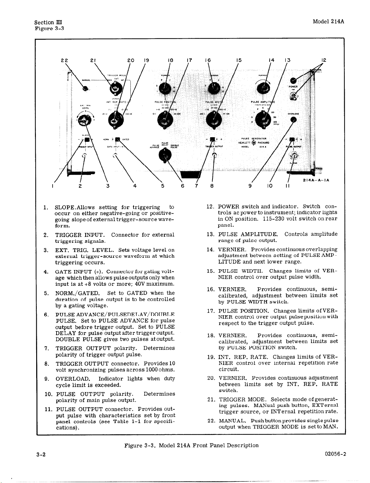
SLOPE.Allows setting for triggering to
1.
occur on either negative-going or positivegoing slope of external trigger-source waveform.
TRIGGER INPUT. Connector for external
2.
triggering signals.
3. EXT. TRIG. LEVEL. Sets voltage level on
external trigger-source waveform at which
triggering occurs.
4. GATE INPUT (+). Connector for gating volt-
age which then allows pulse outputs only when
input is at +8 volts or more; 40V maximum.
5. NORM./GATED. Set to GATED when the
duration of pulse output is to be controlled
by a gating voltage.
6. PULSE ADVANCE/PULSEDELAY/DOUBLE
PULSE. Set to PULSE ADVANCE for pulse
output before trigger output. Set to PULSE
DELAY for pulse output after trigger output.
DOUBLE PULSE gives two pulses atoutput.
7. TRIGGER OUTPUT polarity. Determines
polarity of trigger output pulse.
8. TRIGGER OUTPUT connector. Provides 10
volt synchronizing pulses across 1000 ohms.
9. OVERLOAD. Indicator lights when duty
cycle limit is exceeded.
10. PULSE OUTPUT polarity.
polarity of main pulse output.
11. PULSE OUTPUT connector. Provides output pulse with characteristics set by front
panel controls (see Table l-l for specifi-
cations).
3 4 6 i 6
Determines
IO II
12. POWER switch and indicator. Switch controls ac power to instrument; indicator lights
in ON position. 115-230 volt switch on rear
panel.
13. PULSE AMPLITUDE. Controls amplitude
range of pulse output.
14. VERNIER. Provides continuous overlapping
adjustment between setting of PULSE AMPLITUDE and next lower range.
15. PULSE WIDTH. Changes limits of VER-
NIER control over output pulse width.
16. VERNIER. Provides continuous, semicalibrated, adjustment between limits set
by PULSE WIDTH switch.
17. PULSE POSITION. Changes limits ofVERNIER control over output pulse position with
respect to the trigger output pulse.
18. VERNIER. Provides continuous, semi-
calibrated, adjustment between limits set
by PULSE POSITION switch.
19. INT. REP. RATE. Changes limits of VER-
NIER control over internal repetition rate
circuit.
20. VERNIER. Provides continuous adjustment
between limits set by INT. REP. RATE
switch.
21. TRIGGER MODE. Selects mode of generat-
ing pulses. MANual push button, EXTernal
trigger source, or INTernal repetition rate.
22. MANUAL. Pushbutton provides singlepulse
output when TRIGGER MODE is set to MAN.
3-2 02056-2
_--...

Model 214A
Paragraphs 3-9 to 3-19
Section III
PULSE operation, the minimum allowable PULSE
POSITION setting depends on the PULSE WIDTHused;
this is explained in Paragraph 3-9.
3-9. MINIMUM SPACING WITH DOUBLE
PULSES.
3-10. In DOUBLE PULSE operation, the PULSE
POSITION control sets the spacing between the start
of the first pulse and the start of the second pulse.
For proper operation without affecting pulse shape,
there are minimum spacing limits between the two
pulses, and these limits depend on the PULSE WIDTH
setting.
between pulses is 1 psec. For other PULSE WIDTH
settings, the minimum spacing is 25% of the upper
limit of range selected. For example, if PULSE
WIDTH is set to 100-lK, the minimum spacing
between pulses is 25% of 1K microseconds, or 250
microseconds.
characteristics as set by the Model 214A controls in
DOUBLE PULSE mode. Note from Figure 3-2 that
the setting of PULSE POSITION and PULSE WIDTH
controls the actual spacing between pulses. The
spacing between pulses is then the PULSE POSITION
setting minus the PULSE WIDTH setting.
3-11. GATING OF PULSES.
3-12. By applying a positive signal voltage to the
GATE INPUT (+) connector and sliding the switch to
GATED, pulses will occur at the output only when the
gating signal is at +8 volts or greater. The maximum
gating signal amplitude is +40 volts. To ensure that
output pulses occur when the gate signal just reaches
+8v, a fast rise time input should be used. If a gating
sine wave signal is used, a larger amplitude (but less
than 40 volts peak) will generally provide better results.
and repetition rate must be locked together. Figure
3-4 illustrates the result of gating the pulse output.
3-13. OPERATING PROCEDURES.
3-14. MANUAL TRIGGER MODE.
3-15. When TRIGGER MODE is set to MAN. and the
MANUAL button is pushed, a single pulse output will
occur. Other front panel controls are set to obtain
For a 0.05-l setting the minimum spacing
Figure 3-2 shows the output pulse
For synchronized pulse trains, the gating signal
the desired pulse characteristics. The same operating
considerations apply as explained in Paragraphs 3-4,
3-7, and 3-9. The maximum rate for pushbutton
pulses is 2 cps.
3-16. EXTERNAL TRIGGER MODE.
3-17. With TRIGGER MODE set to EXT., an external
triggering signal from dc to 1 MC with 0.5 volts peak
amplitude is required to generate pulses in the Model
214A.
proceed as follows:
to TRIGGER INPUT.
gering level on input waveform. Polarity of EXT.
TRIG. LEVEL must agree with SLOPE setting.
using an external gating signal.
DELAY/DOUBLE PULSE. PULSE ADVANCE or
PULSE DELAY means the output pulse will occur
advanced or delayed in time, with respect to the
trigger output pulse. DOUBLE PULSE provides two
pulses out at a rate determined by the TRIGGER
MODE circuits.
nect coaxial cable to external circuit being triggered.
these amplitudes are volts into a 50 ohm load at the
PULSE OUTPUT connector. The 100 v range will not
produce a pulse without the 50 ohm termination.
NIER. Observe duty cycle limit for amplitude range.
coaxial cable to external test circuit.
NIER as desired. With PULSE ADVANCE or PULSE
DELAY operation. PULSE POSITION setting is the
spacing between the pulse output and the trigger output
pulse. With DOUBLE PULSE, PULSE POSITION sets
the spacing between the two pulses.
position, width, and amplitude characteristics.
Refer to Paragraphs 3-4, 3-7, and 3-9 and
a. Set TRIGGER MODE to EXT. and connect signal
b. Select + or - SLOPE setting.
c. Set EXT. TRIG. LEVEL to obtain desired trig-
d. Set GATED/NORM. switch to NORM. unless
e. Select setting for PULSE ADVANCE/PULSE
f. Select polarity of TRIGGER OUTPUT and con-
g. Select PULSE AMPLITUDE range. Note that
h. Select PULSE WIDTH range and adjust VER-
i. Select polarity of PULSE OUTPUT and connect
j. Select PULSE POSITION range and adjust VER-
k. Adjust VERNIERS if necessary to obtain exact
nnnnnnn nnn
MODEL 214A PULSE OUTPUT
2 I
GATE INPUT SIGNAL
Figure 3-4. Gating Pulse Output
02056-3
1
214*-*-
3-18. INTERNAL TRIGGER MODE.
3-19. With TRIGGER MODE set to INT.. the Model
214A will generate pulses at a rate set by the INT.
REP. RATE range and VERNIER. This repetition
rate is adjustable from 10 cps to 1 MC. Refer to
Paragraphs 3-4, 3-7? and 3-9 and proceed as follows:
a. Turn instrument POWER switch to ON and allow
several minutes for warmup.
b. Set TRIGGER MODE to INT.
c. Set INT. REP. RATE range and VERNIER to
approximate position for frequency desired (maximum frequency is fully clockwise).
d. Complete steps d through k of Paragraph 3-16.
3-3

El 00,
.4 /iSEC
+
0,
DELAY
CIRCUIT
V2028 B DL201 --o V203 El T202
0,
\
\
POSITION POSITION
MONOSTABLE
b-+ MULTIVIBRATOR -
V20lA,V202A,
VI048
--oI \-
0
,-. l
\
\
BLOCKING
OSCILLATOR
VZOIB 8 T201
\
TRIGGER
OUTPUT
BLOCKING
OSCILLATOR
-\
\
\
\ ’
<
\
-c* DIODE
<
/
\
[PULSE DELAY 1
lDOuBLE PULSE 1
\
\
\
1
CR208
, DIODE -
CR207
PULSE ADVANCE
\
\
,-
0
START
1
1 v204A 8. DL202 1 1 V205A 8 T203 1 1 1
I
PULSE
Q’ “‘;KING
1ATl-N
1 I
STOP SIGNAL
Figure
,;;;iR
V301 8. T301
1
I
4-l. Model 214A Block Diagram
BISTABLE
MULTIVIBRATOR
AND POWER
AMPLIFIER
v304, v305,0301
POLARITY
AND
ATTENUATION

Model 214A
Paragraphs 4-l to 4-12
SECTION IV
PRINCIPLES OF OPERATION
4-1. GENERAL. 4-7. MANUAL TRIGGER OPERATION.
4-2. The complete circuit operation is shown in
Figure 4-1.
lowing general sequence: a trigger pulse from the
rate circuit (VlOZ), functioning either as a Schmitt
trigger or an astable multivibrator, is applied to
blocking oscillator V103, which triggers both the
Position Multivibrator (V201A, VZOZA, V104B) and
blocking oscillator V203 for the trigger output pulse.
The position Multivibrator triggers Position Blocking
Oscillator V201B which in turn triggers both start
and stop pulse circuits.
are used to switch a bistable multivibrator-power
amplifier combination (V304, V305, Q301) which
forms the output pulse. The details of each block
are contained in the schematics, and the following
circuit description explains the operation of each
circuit, both as to basic type and to the part it plays
in the sequence of forming the output pulse.
4-3. INPUT AND RATE GENERATOR.
4-4. EXTERNAL TRIGGER OPERATION.
4-5. With TRIGGER MODE set to EXT. position, a
signal of at least 0.5 volts peak will cause Differential
Amplifier VlOl to amplify the difference between the
levels at the control grids, pins 2 and 7. TRIGGER
SLOPE switch SlOl routes the trigger input to one
grid of VlOl and also transfers the external trigger
level circuit of R105 to the other grid. Resistor R105
sets the grid bias which must be overcome by the
trigger input at the other grid to obtain an output at
the plate, pin 6 of V101. The output from VlOl is
coupled through S103A, through a low-impedance
network (DSlOl, R116, and C107), and S103B to R125
and the grid of V102.
The output pulse is formed by the fol-
The start and stop pulses
4-8. With TRIGGER MODE set to MAN. position,
V102 again functions as a Schmitt Trigger circuit as
in external operation, with the parallel RC network
R129-Cl10 coupling between plate and grid. When
MANUAL switch S102 is energized, the side of capacitor Cl06 toward the switch charges toward +150 volts
through R120. This positive-going, slow rising ex-
ponential voltage is coupled to the grid (pin 2) of V102
and the left half of the tube conducts. The right half
of V102 now cuts off and a positive pulse to +15OV is
the output coupled to the grid of V103.
4-9. INTERNAL TRIGGER OPERATION.
4-10. With TRIGGER MODE set toINT. position, V102
functions as an astable multivibrator. The free-
running rate of this circuit is controlled by range
capacitors, Cl13 through C117, couplingbetweenplate
(pin 1) and grid (pin 7), and by VERNIER, R137.
Breakdown diode CR101 sets the bias at the grid of
the left half of V102. This circuit has no stable state
and is always changing between two states: (1) lefthalf cutoff, right-half conducting or (2) left-half conducting, right-half cutoff. The rate at which this
changing of states occurs is primarily a function of
the capacitors between plate and grid since this determines the exponential rise and decay time of the
grid (pin 7). When the grid (pin 7) voltage rises
exponentially enough to cause the right half to conduct,
the output at pin 6 is about +125 volts. Then as the
voltage at pin 7 decays exponentially, the right half
cuts off and the output at pin 6 is at the supply voltage,
+15Ov. A regenerative action occurs as the right half
of V102 just starts to conduct and the left half starts
to cutoff: the increase in voltage at the plate (pin 1)
is coupled through the range capacitor to speed turn
on of the right half. Symmetry Adjust, R133, changes
the grid bias of pin 7 to nearly equal the bias at pin 2
making the two halves of the waveform equalin width,
Section IV
4-6. In external trigger operation, V102 functions
as a cathode-coupled binary, or Schmitt Trigger,
circuit. The plate to grid coupling network is from
pin 1 through S103B and the parallel RC combination,
R129-C110, to the grid, pin 7. The left half of V102
is normally off and the right half conducting so the
output at pin 6 is at a positive level (about 125 volts),
less than the +150 supply. As the signal at pin 2
becomes positive enough (upper hysteresis limit),
the left half of V102 conducts and regenerative action
cuts the right half off. When the input at pin 2 decreases enough (lower hysteresis limit), the left half
of V102 is cut off and the circuit returns to the original
state. The output at pin 6 then is a positive pulse each
time the signal at pin 2 causes the left half to conduct,
and the rate at which this occurs is exactly that of
the external trigger signal (1 MC limit on input frequency). The output pulse from pin 6 is coupled
through Cl22 to pin 2 of Blocking Oscillator V103.
02056-2
4-11. TRIGGER BLOCKING OSCILLATOR.
4-12.
Tube V103 and transformer TlOl function as an
amplifier-blocking oscillator, when the output of
V102 is not being gated by the circuit of V104A (see
Paragraph 4- 13). Normal operation of the blocking
oscillator is as a monostable circuit being triggered
by an amplified signal. The left half of V103 amplifies
the positive pulse at its grid and the resulting plate
pulse is coupled through transformer TlOl, reversed
in phase, to the grid of the right half. This puts the
right half of V103 in conduction and a regenerative
action drives the plate (pin 6) voltage down abruptly
and the grid voltage (pin 7) abruptly positive. Next
the action reverses and as the plate voltage becomes
more positive, the grid goes negative and regeneration
turns the tube off agian. The output is taken from the
cathode (pin 8) and the pulse drives other circuits de-
pending on which pulse mode (advance, delay, or
double) is used (see Paragraph 4-15).
4-l

Section IV
Paragraphs 4-13 to 4-30
Model 214A
4-13. GATE INPUT CIRCUIT.
4-14. When switch S105 is in the NORM. position,
Gate Cathode Follower V104A is conducting enough so
CR103 is biased off, and the pulse at pin 2 of V103 is
unaffected in operation.
However, when S105 is moved
to GATED, V104A is cut off, biasing the cathode of
CR103 more negative than its anode and CR103 conducts, changing V103 input impedance so the rate pulse
does not develop enough signal to trigger the blocking
oscillator. By applying a positive signal of at least
8 volts (but less than 40) V104A will again conduct,
cutting off CR103 and the pulse at V103 triggers the
blocking oscillator (explained in Paragraph 4-l 1).
4-15. ADVANCE, DELAY, DOUBLE PULSE
MODES.
4-16. Three modes of pulse operation are obtained
by switching the timing pulse from the Trigger Blocking Oscillator V103 through combinations of circuits.
These circuits are described below first in terms of
general operation (Paragraphs 4-17 through 4-26)
and second, as each is used in either PULSE AD-
VANCE, PULSE DELAY, or DOUBLE PULSE (Para-
graphs 4-27 through 4-32).
4-17. PULSE POSITION CIRCUIT.
4-18. POSITION MULTIVIBRATOR. The circuits of
tubes V201A and V202A form a monostable multi-
vibrator which controls the position relationship between the output pulses and trigger output or between
both output pulses in DOUBLE PULSE operation. This
multivibrator substitutes cathode-coupling with a
common cathode resistor for the usual coupling between plate of V202A and grid of V201A, but still is
a monostable circuit. The width of the multivibrator
pulse is controlled by range capacitors, C201 through
C205, and the VERNIER control R207. By controlling
the time V202A is cut off, with the range capacitor
and VERNIER, the delay before triggering theposition
blocking oscillator V201B is also controlled (V201B
is triggered as V202A starts conducting; see Para-
graphs 4- 19). Tube V104B acts as a screen biasing
supply for V202A.
The output at pin 9 of V202A is a
variable width positive pulse which is coupledthrough
C209 to pin 6 of V201B.
4-19. POSITION BLOCKING OSCILLATOR. The signal from V202A triggers Position Blocking Oscillator V201B at the plate. This signal is coupled
through T201 to the grid (pin 7) and the circuit functions
in the same way as V103 right half, described in
Paragraph 4-11. The output is takenfromthe cathode
as a positive pulse about 30 volts in amplitude.
4-20. PULSE WIDTH MULTIVIBRATOR.
4-21.
The circuits of tubes V206A and V204B form a
monostable, cathode-coupled multivibrator, and the
circuit functions the same as that described in Paragraph 4-18. The time for whichV204Bremains cutoff
is determined by range capacitors C225 through C229
and VERNIER, R257. The output at pin 9 of V204B is
used to drive the stop pulse blocking oscillator V206B
(see Paragraph 4-26). The time delay obtained from
the width multivibrator thus determines how long since
4-2
the output pulse started before the stop pulse blocking
oscillator returns the pulse to zero (this time is the
pulse width).
4-22. TRIGGER OUTPUT BLOCKING
OSCILLATOR.
4-23. Tube V203 and transformer T202 function as an
amplifier-blocking oscillator in a nearly identical
circuit as described in Paragraph 4-11 for the circuit
of v103.
A signal at pin 2 of V203 is amplified and
coupled from the plate through T202 to the grid of the
right half. For a positive trigger output, S203 routes
the cathode signal to 5201 and for a negative trigger
out, S203 routes the signal from pin 1 of T202 to 5201.
4-24. START-STOP PULSE BLOCKING
OSCILLATORS.
4-25. START PULSE BLOCKING OSCILLATOR. The
circuit of V205A and T203 is another blocking oscillator working the same way as described in Paragraph 4-11. The signal which triggers V205A plate
has been amplified by V204A and delayed by 0.14
microseconds by DL202. The output from thecathode
of V205A is a positive pulse of about 35 volts which
drives the input to V301.
4-26. STOP PULSE BLOCKING OSCILLATOR. The
blocking oscillator of V206B and T204 also is of the
same type already described in Paragraph 4-11. The
signal to trigger V206B comes from the width multivibrator circuit when V204B starts conducting. The
output from the cathode of V206B is a positive pulse
of about 35 volts and it drives the input to V303, the
Stop Pulse Spiker.
4-27. PULSE ADVANCE TIMING LOGIC.
4-28. Figure 4-2 shows the timing logic for PULSE
ADVANCE mode of operation. The timing pulse from
V103 goes directly through diode CR207 to the start-
stop pulse circuits (through V204A to V205A, and
through the width multivibrator to V206B). The timing
pulse also goes through CR201 to the grid of V201A
to operate the position multivibrator. The resulting
waveform from the position blocking oscillator is
coupled through C216 to pin 2 of V203. Now the posi-
tion multivibrator is used to effectively delay the trig-
ger output, i.e. the main pulse output occurs in
advance of the trigger.
The pulse width multivibrator
and start-stop pulse blocking oscillators function the
same as described previously.
4-29. PULSE DELAY TIMING LOGIC.
4-30. Figure 4-3 shows the timing logic for PULSE
DELAY mode of operation. The V103 timing pulse
goes directly to Cathode Follower V202B andis taken,
delayed by 0.4 microseconds by DL201, throughS202B
to the trigger output blocking oscillator, to cause a
trigger output pulse. The timing pulse has also triggered theposition multivibrator circuit throughCR201.
The output from V201B goes through CR208 and S202B
to the width multivibrator and start-stop blocking
oscillators.
This time the position multivibrator has
been used to effectively delay the start of the pulse
output with respect to the trigger output.
02056-l

Model 214A
Section TV
Paragraphs 4-31 to 4-36
RATE
GVEi%%R.
POSITION
V%A
P”X!oN
V2blB
TRIGGER
OUT PUT
PULSE
WIDTH
M.V.
V204B
STOP
svp:oK3E
PULSE
OUTPUT
OUTPUT
AS SEEN
)N SCOPE
SEQUENCE OF EVENTS
PULSE ADVANCE
t‘l
1
I
I
I
,
I
I
I
h
r
1
l
t
1
l
t
t
w
t
SEQUENCE OF EVENTS
PULSE DELAY
to
RATE
GvEIYiRR.
Rk%:
VI03
rRLGGER
DUTPUT
‘OSITION
M.V.
V202A
‘“sB!To!oN
V201B
ssTp?KRET
v30 I
2%
M.V.
V204B
STOP
SPIKE
v303
PULSE
OUTPUT
OUTPUT
AS SEEN
IN SCOPE
b
t5
1 1
h
h
f
h
l
t
b
t
c
b
t
t
b
t
b
Figure 4-2. PULSE ADVANCE Timing Sequence Figure 4-3. PULSE DELAY Timing Sequence
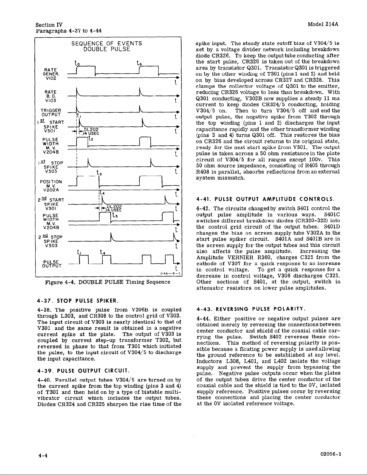
4-31. DOUBLE PULSE TIMING LOGIC.
4-32. Figure 4-4 shows the timing logic for DOUBLE
PULSE mode of operation. The V103 timingpulse goes
directly through CR201 to the position multivibrator
and directly through CR207 to the start pulse and stop
pulse circuitry (i.e. through V204A and also through
the width multivibrator). This causes one pulse output. Then the delayed timing pulse from the position
multivibrator and blocking oscillator comes through
CR208 to trigger the start-pulse circuitry a second
time and another pulse output is formed. The delayed
timing pulse from V201B determines the position in
time at which the second pulse occurs (i.e. the time
between leading edge of pulses). The pulses have the
same variable width since both are controlled by the
width multivibrator.
4-33. FORMING AND CONTROLLING
OUTPUT PULSE.
4-34. The fast rise and fall time of the output pulse is
achieved by rapid charging of the input capacitance
represented by the grid of tubes V304 and V305, then
02056-l
rapidly discharging this capacitance to end the pulse.
A large current spike waveform is used and the output
tubes are held on during the pulse by a bistable type
multivibrator circuit. The amplitude of the output
pulse is controlled by varying the output tube screen
supply, by changing the bias levels of the output circuits, and some attenuation at the output,
4-35. START PULSE SPIKER.
4-36. The positive pulse from V205A is coupled
through L301, C301, and CR301 to the control grid of
v301. The input circuit of V301 changes the dc level
of the start pulse and smoothes the transition from
triggered on state to the steady stateduring the output
pulse. Diode CR301 discharges the input circuit after
the start spike occurs and C302 discharges through
R301 to increase the fall time of the spike. The rise
time of the spike is sharpened by clipping diode CR303.
Tube V302A is a screen supply for V301. The output
of V301 is a current spike which is increased to about
0.5 amp by current step-up transformer T301 and
coupled to the input circuit of V304/5 to charge
input capacitance.
up
the
4-3
Section IV
Paragraphs 4-37 to 4-44
Model 214A
SEQUENCE OF EVENTS
DOUBLE PULSE
h
P°K!oN
I
2@ START
SVP21E
PULSE
*K”
v2oie
2~~~r:p h L
v303
PULSE
OUTPUT
Figure 4-4. DOUBLE PULSE Timing Sequence
1
I
214&--B-,
spike input. The steady state cutoff bias of V304/5 is
set by a voltage divider network including breakdown
diode CR326. To keep the output tube conducting after
the start pulse, CR326 is taken out of the breakdown
area by transistor Q301. Transistor Q301 is triggered
on by the other winding of T301 (pins 1 and 2) and held
on by bias developed across CR327 and CR328. This
clamps the collector voltage of Q301 to the emitter,
reducing CR326 voltage to less than breakdown. With
Q301 conducting, V302B now supplies a steady 11 ma
current to keep diodes CR324/5 conducting, holding
V304/5 on.
Then to turn V304/5 off and end the
output pulse, the negative spike from T302 through
the top winding (pins 1 and 2) discharges the input
capacitance rapidly and the other transformer winding
(pins 3 and 4) turns Q301 off. This restores the bias
on CR326 and the circuit returns to its original state,
ready for the next start spike from V301. The output
pulse is taken across a 50 ohm resistancein the plate
circuit of V304/5 for all ranges except 100~. This
50 ohm source impedance, consisting of R405 through
R408 in parallel, absorbs reflections from an external
system mismatch.
4-41. PULSE OUTPUT AMPLITUDE CONTROLS.
4-42. The circuits changedby switch S401 control the
output pulse amplitude in various ways. s401c
switches different breakdown diodes (CR320-322) into
the control grid circuit of the output tubes. S401D
changes the bias on screen supply tube V302A in the
start pulse spiker circuit. S401A and S401B are in
the screen supply for the output tubes and this circuit
also affects the pulse amplitude.
Increasing the
Amplitude VERNIER R360, charges C325 from the
cathode of V307 for a quick response to an increase
in control voltage. To get a quick response for a
decrease in control voltage, V308 discharges C325.
Other sections of S401, at the output, switch in
attenuator resistors on lower pulse amplitudes.
4-37. STOP PULSE SPIKER.
4-38. The positive pulse from V206B is coupled
through L303, and CR308 to the control grid of V303.
The input circuit of V303 is nearly identical to that of
V301 and the same result is obtained in a negative
current spike at the plate. The output of V303 is
coupled by current step-up transformer T302, but
reversed in phase to that from T301 which initiated
the pulse, to the input circuit of V304/5 to discharge
the input capacitance.
4-39. PULSE OUTPUT CIRCUIT.
4-40. Parallel output tubes V304/5 are turned on by
the current spike from the top winding (pins 3 and 4)
of T301 and then held on by a type of bistable multivibrator circuit which includes the output tubes.
Diodes CR324 and CR325 sharpen the rise time of the
4-4
4-43. REVERSING PULSE POLARITY.
4-44. Either positive or negative output pulses are
obtained merely by reversing the connections between
center conductor and shield of the coaxial cable carrying the pulse. Switch S402 reverses these connections. This method of reversing polarity is
pas-
sible because a floating power supply is usedallowing
the ground reference to be established at any level.
Inductors L308, L401, and L402 isolate the voltage
supply and prevent the supply from bypassing the
pulse.
Negative pulse outputs occur when the plates
of the output tubes drive the center conductor of the
coaxial cable and the shield is tied to the OV, isolated
supply reference. Positive pulses occur by reversing
these connections and placing the center conductor
at the OV isolated reference voltage.
02056-l
.l.-l-_. .--”
-_

Model 214A
Paragraphs 5-l to 5-7
Section V
SECTION V
MAINTENANCE
5-1. INTRODUCTION.
5-2. This section covers maintenance, troubleshooting, and adjustment of the Model 214A Pulse
Generator. The performance check, Paragraph 5-3,
may be used in incoming inspection or after adjustments have been made to verify that the instrument
meets its specifications (Table l- 1).
5-3. PERFORMANCE CHECK.
5-4. The performance check is intended to determine whether or not the instrument is operating within
its specifications.
to Paragraph 5-17.
If adjustment is necessary, refer
Test equipment recommended
for the performance check is listed in Table 5-1,
items 1 through 13. Similar instruments having the
listed characteristics may be substituted.
5-5. EXTERNAL GATING.
a. Connect Model 214A PULSE OUTPUT to High
Frequency Oscilloscope Channel A INPUT,
b.
Connect external Power Supply to Model 214A
GATE
INPUT.
C.
Set Model 214A:
INT. REP RATE. . . . . . . . . . . . . l-10
Int. Rep. Rate VERNIER
fully cw
TRIGGER MODE. . . . . : : : : : : . . . INT
GATE INPUT . . . . . . . . . . . . . GATED
PULSE WIDTH. . . . . . . . lo- 100
Width VERNIER . . . . . . . : : : : Midrange
PULSE AMPLITUDE . . . . . . .
PULSE POSITION . . . . . . . . . .
2 VOLTS
lo- 100
Position VERNIER. . . . . . . . . . fully cw
d.
Set Oscilloscope and Plug-In:
SWEEP TIME. , . ,
Channel A SENSITIVITY : : : .
TRIGSOURCE . . . . . . . . . : : . . .
20 &SEC/CM
1 V/CM
INT
e. Increase voltage output of Power Supply from 0
volts until 214A gates on. Gating voltage should be
8 volts or less.
5-6. EXTERNAL TRIGGERING.
Connect output of Audio Oscillator to Model 2 14A
a.
TRIGGER INPUT.
b. Connect Model 214A PULSE OUTPUT to Oscillo-
scope Plug-In Channel A INPUT.
c. Set Model 214A:
PULSE AMPLITUDE. . . . . . .
10 VOLTS
Amplitude VERNIER . . . . . . . . . . . . cw
TRIGGER MODE . . . . . . . . . . . . . EXT
PULSE WIDTH . . . .
.05-l
WidthVERNIER . . . . . ...:::... 3
d. Set Oscilloscope and Plug-In:
Channel A SENSITIVITY 2v/cm with 50 ohm-
load or 5v/cm without 50 ohmload
SWEEP TIME . . . . . . . . . . 0.1 psec/cm
TRIG SOURCE . . . . . . . . . . . . . . INT
e. Set Oscillator frequency to 200 kc andOscillator
amplitude for l/2 volt peak-to-peak.
f. Model 214A shouldtrigger on both + and - slope
by adjusting EXT TRIG LEVEL.
5-7. PULSE AMPLITUDE AND WIDTH.
a. Connect aBNC Tee to High Frequency Oscillo-
scope Plug-In Channel A INPUT. A 50-ohm, 1%
resistor witharating of at least 10 watts (such as the
hp 50-ohm load recommended in Table 5-1, Item 10)
should be connected as a load to the Tee. Connect the
Tee to the Model 214A PULSE OUTPUT with a BNC
to BNC cable.
b. Connect Oscilloscope TRIGGERINPUT toMode
214A TRIGGER OUTPUT with BNC to BNC cable.
c. Set Model 214A:
INT REP RATE. . . . . . . . . . .
. Ol-. 1
Int. Rep. Rate VERNIER. . . . . . Midrange
PULSE POSITION . . . . . . . . . . . l-10
Position VERNIER . . . . . . . . . . . . . 1
PULSE WIDTH . . . . . . . . . . . lK- 10K
Width VERNIER. . . . . . . . . . . fully ccw
PULSE AMPLITUDE . . . . . .
100 VOLTS
Amplitude VERNIER . . . . . . . . . fully cw
TRIG MODE. . . . . . . . . . . . . . . . INT
d. Set Oscilloscope and Plug-In:
Channel Selector . . . . . . . . CHANNEL A
Channel A SENSITIVITY . . . . .
SWEEP TIME . . . . . . .
20 V/CM
0.1 MSEC/CM
Int SWEEP MAGNIFIER . . . . . . . . . . Xl
TRIG SOURCE . . . . . . . . . . . . . . EXT
e. There should be at least 100 volts (5 cm) of
vertical display.
f. Set Model 214A PULSE WIDTH to .05-l.
PULSE POSITION . . . . . . . . . . . . O-l
Pulse Position VERNIER . . . . . . . . CCW
g. Set Oscilloscope:
SWEEP TIME. . . . . . . . . 0.1 /JSEC/CM
Int SWEEP MAGNIFIER . . . . , . . . . X10
h. There should be at least 50 nanoseconds (5 cm)
of horizontal display measured at half amplitude of
pulse.
i. Set Model 214A:
PULSE AMPLITUDE , . . . . . 0.2 VOLTS
PULSE WIDTH . . . . . . . . . . .
lK- 10K
Width VERNIER . . . . . . . . . . . fully cw
Rep Rate VERN . . . . . . . . . . . fully ccw
j. Set Oscilloscope and Plug-In:
Channel A SENSITIVITY . . . . . 05 V/CM
SWEEP TIME. . . . . . . . .
2 I&EC/CM
Int SWEEP MAGNIFIER . . . . . . . . . . Xl
k. There should be at least lOmilliseconds (5 cm)
of horizontal display.
m. Set Model 214A Amplitude VERNIER fully ccw.
02056-3
5-l

Section V
Paragraph 5-8
Model 214A
Table 5-l. Equipment Required for Tests and Adjustments
Item
Equipment Name or Part Req’d Required Ref. Para.
1 Power Supply
Model
‘@ 723A
No.
1 Performance 5-5
Check
Audio Oscillator c@ 200CD 1 Performance 5-6 0.5 volt peak-to-peak,
Check 200 kc
Variable Attenuator @ 355D
1 Performance 5-12 thru 5-14 50-ohms,
Check
Sampling Oscillo- @ 185B
scope and Plug-in
‘@ 187B
5 50 -ohm Load ~$3 908A 1
1 Performance 5-13 thru 5-16 800 MC Bandwidth, dual
1. Check
Performance 5-13, 5-14 Type N connector, 50
Check & Adj ohms, SWR<l. 05, l/2 W
6 50-ohm Tee @ 10204B
1
Performance 5-13 thru 5-16 Type N 50 ohm Tee for
Check
7 BNC to Type N @10122A 1 Performance
Cable
Check male, 50 ohms * l/2 ohm
8 BNC to Dual Banana @llOOlA 1 Performance 5-6
Cable
Check 50 ohm cable
Required
Characteristics
At least 8V output
120 db attenuation
channel, Sensitivity
5 mv/cm
Sampling Oscilloscope
Probe
5-13 thru 5-16 Type N male to BNC fe-
BNC male to dual banana
9 BNC Female to Type N@ 1250- 1 Performance 5-15 BNC female to Type N
N Male Adapter
0067 Check male
10 50-ohm Load @5060- 1 Performance 5-7 thru 5-12 50 ohms, l%, 20watts
0426 Check
11 50 ohm Tee @1250- 1 Performance 5-7 thru 5-11; BNC male to BNC female
0072 Check and 5-26 to BNC female
Adjustments
12 BNC to BNC Cable @10503A 2 Performance 5-7 thru 5-14; BNC male to BNC male
Check and 5-26, 5-2’7 50 ohm Cable
Adjustments
13
High Frequency @ 175A 1
Oscilloscope, Plug- c@ 1750B 1
Ins and Probes
14
DC Voltmeter @412A
@1780A 1
Performance 5-5 thru 5-12; 40 MC Bandwidth, dual
Check and 5-23 thru5-27 channel
Adjustments
1
Adjustments 5-21, 5-26 Range 0 - 600 volts,
accuracy 1%
15 DC Milliammeter ~$3 428B 1 Adjustments 5-25 Range 0 - 50 ma, clip on
Probe, + 3% accuracy
n, There should be 1. 6 cm ( 80 mv ) or less of
vertical display.
5-8. PULSE POSITION.
a. Connect a BNC Tee to Oscilloscope Plug-in
Channel A INPUT. Connect 50-ohm load (at least
10 W) to Tee. Connect the Tee to the Model 214A
PULSE OUTPUT with a BNC to BNC cable.
b. Connect a BNC Tee Oscilloscope TRIGGER
INPUT. Connect the Tee to the Model 214A TRIGGER
OUTPUT with BNC to BNC cable. Connect the Tee to
Oscilloscope PLUG-in Channel B INPUT with BNC to
BNC cable.
5-2
c. Set Model 214A:
PULSE AMPLITUDE ......
a ... 10 VOLTS
Amplitude VERNIER ........... fully
PULSE WIDTH ............... lo- 100
Width VERNIER .............. fully ccw
TRIGGER OUTPUT .... ,
........ , , .. +
PULSE OUTPUT.. ................. +
PULSE POSITION .............. lo-100
Position VERNIER ............. fully ccw
ADVANCE/DELAY/DOUBLE . . PULSE DELAY
INT. REP. RATE ...............
Int. Rep. Rate VERNIER ......... fully
02056- 3
ccw
l-10
ccw
---._-- --

Model 214A
Section V
Paragraphs 5-Q to 5-11
d. Set Oscilloscope and Plug-In:
Channel A SENSITIVITY , . . . . . . . . 1 V/CM
Channel B SENSITIVITY . , . , . . . . . 5 V/CM
Channel Selector . . . . . . . . . . . ALTERNATE
TRIGGERSOURCE............. EXTAC
TRIGGER SLOPE. . . . . . . . . . . . . . . . . . . +
SWEEP TIME . . . . . . . . . . . . . 10 @EC/CM
Int SWEEP MAGNIFIER . . . . . . . . . . . . . Xl
e. Position Channel A and Channel B traces on
Oscilloscope graticule.
f. By adjusting Model 214A Position VERNIER
from fully ccw to fully cw, the pulse on Channel A
should sweep 100 p set (10 cm).
g. Reverse cables to Model 214A PULSE OUTPUT
and TRIGGER output.
h. Set ADVANCE/DELAY/DOUBLE to PULSE AD-
VANCE.
i. By adjusting Model 214A Position VERNIER
from fully ccw to fully cw the trigger spike displayed
on Channel A should sweep 100 p set (10 cm).
j. Reverse cables to Model 214A PULSE OUTPUT
and TRIGGER OUTPUT (original position).
5-9. DOUBLE PULSE AND MANUAL
TRIGGERING.
a. Connect a BNC Tee to Oscilloscope Plug-in Chan-
nel A INPUT. Connect 50-ohm load (10 ,W) to Tee.
Connect the Tee to the Model 214A PUISE OUTPUT
with a BNC to BNC cable.
b. Connect Oscilloscope TRIGGER INPUT to the
Model 214A TRIGGER OUTPUT with BNC to BNC
cable.
c. Set Model 214A:
PULSE AMPLITUDE . . . . . . . , . . . . .
10 V
Amplitude VERNIER. . . . . . . . . . , . . fully cw
TRIG. MODE. . . . . . . . . . . . . . . . . . . . INT.
PULSE WIDTH . . . . , . . . . . . . . . . . . .05- 1
Width VERNIER. . . . . . . . . . . . . . . . . . . 3
PULSE POSITION . . . . . . . . . . . . . . l-10
Position VERNIER . . . , . . . . . . . . . fully cw
ADVANCE/DELAY/DOUBLE . DOUBLE PULSE
d. Set Oscilloscope and Plug-In:
Channel Selector . . . . . . . . . . . CHANNEL A
Channel A SENSITIVITY . . . . , . . . . 2 V/CM
SWEEP TIME . . . . . . . . . . . , . . 1 pSEC/CM
Int SWEEP MAGNIFIER . . . . . . . . . . . . . Xl
e. Adjust Model 214A Position VERNIER fully ccw.
Spacing between pulses should be 1 psec (lcm) or
less.
f. Set Model 214A TRIGGER MODE to MAN.
position.
g. One complete cycle should be observed on oscil-
loscope CRT each time MANUAL push button is
pressed.
5-10. INTERNAL REP RATE.
a. Connect a BNC Tee to Oscilloscope Plug-In
Channel A INPUT. Connect 50-ohm load (.lO W) to Tee.
Connect the Tee to the Model 214A PULSE OUTPUT
with a BNC to BNC cable.
02056- 4
b. Connect Oscilloscope TRIGGER INPUT to the
Model 214A TRIGGER OUTPUT with BNC to BNC
cable.
Set Model 214A:
PULSE AMPLITUDE.
Amplitude VERNIER.
PULSE WIDTH.
Width VERNIER.
...............
............... fully cw
...........
........... fully cw
10 VOLT
lK- 10K
PULSE OUTPUT.. ................. +
INT. REP. RATE. .............
Rate VERMER
PULSE POSITION
...............
................
.Ol - .l
fully ccw
Q-1
Position VERNIER ............. fully ccw
ADV/DELAY/DOUBLE ..... PULSE DELAY
Set Oscilloscope and Plug-In:
Channel Selector . . . . . . . . . . . CHANNEL A
Channel A SENSITIVITY . . . . . . . , . . XV/CM
SWEEP TIME . . . . . . . . . . . . . 20 MSEC/CM
There should be no more than 2 pulses displayed
in 10 cm of sweep.
f.
Set Model 214A:
PULSE WIDTH . . . . . . . . . . . . . . . .05 - 1
Width VERNIER. . . . . . . . . . . . . . . . . . .
INT. REP. RATE. . . . . , . . . . . . . . 100 - 1K
Int. Rep. Rate VERNIER . . . . . . . . . . fully cw
Set Oscilloscope SWEEP TIME to 1 ysec/cm.
g.
h.
At least 10 pulses should be displayed in 10 cm
of sweep.
5-11. DUTY CYCLE.
a. Connect a BNC Tee to Oscilloscope Pl<g-in
Channel A INPUT. Connect 50-ohm load (10 W) to
Tee. Connect the Tee to the Model 2 144 PULSE OUTPUT with a BNC to BNC cable.
b. Connect Oscilloscope TRIGGER INPUT to the
Model 214A TRIGGER OUTPUT with BNC to BNC
CABLE.
C.
Set Model 214A.
TRIGGER OUTPUT
TRIGGER MODE
PULSE WIDTH.
..................
.................
INT.
................ 10-100
Width VERNIER. .............. fully ccw
INT. REP. RATE
Rate VERNIER
............... 1 - 10
...............
fully ccw
PULSE OUTPUT ...................
PULSE AMPLITUDE
Amplitude VERNIER,
PULSE POSITION
Position VERNIER
d.
Set Oscilloscope and Plug-in:
Channel Selector
Channel A SENSITIVITY
Channel A INPUT.
TRIGGER SLOPE.
TRIGGER SOURCE.
SWEEP TIME
.............
Int SWEEP MAGNIFIER
Adjust Position VERNIER until leading edge of
e.
pulse lines up with first vertical line of Oscil-
first
.......... 10 VOLTS
...........
fully cw
............. 10 - 100
.............
fully ccw
........... CHANNEL A
..........
.................
2V/CM
DC
..................
...............
EXT.
16 @KC/CM
............. Xl
loscope graticule.
5-3
3
+
-
+

Section V
Paragraphs 5-12 to 5-14
Model 214A
f. Adjust Int. Rep. Rate VERNIER until leading
edge of second pulse lines up with last vertical line
of Oscilloscope graticule.
g. Adjust width VERNIER; no overload should
occur until pulse width is at least 50 psec (5 cm).
h. Set:
Model 214A Width VERNIER . . . . . . fully ccw
Model 214A PULSE AMPLITUDE . . 20 VOLTS
Oscilloscope Channel A SENSITIVITY
. . . . . . . ..**............
5 V/CM
i. Adjust width VERNIER; no overload should
occur until pulse width is at least 25 psec (2.5 cm).
j. Set:
Model 214A Width VERNIER. . . . . , , fully ccw
Model 214A PULSE AMPLITUDE . . 50 VOLTS
Oscilloscope Channel A SENSITIVITY
. . . .
10 V/CM
Osciil&cbpd &V&&‘&ME : : . . . 2 kSEC/CM
k. Adjust width VERNIER; no overload shouldoccur
until pulse width is at least 10 psec (5 cm).
m. Set Model 214A PULSE AMPLITUDE to 1OOV.
With pulse width at 10 psec (5 cm) the Model 214A
should not overload.
TRIGGER SLOPE. . . . . . . . . . . . . . . . . . . -
TIME SCALE. . . . . . . . . . . . . . . 1 @EC/CM
TIME SCALE MAGNIFIER . . . . . . . . . . Xl0
c. Connect PULSE OUTPUT to the 120 db Variable
Attenuator with BNC to BNC cable.
d. Connect the Attenuator output to the Model
10204B 50-ohm Tee with a BNC to type N cable.
e. Connect the Tee to Channel A probe of Sampling
Oscilloscope.
f. Terminate the Tee with 50-ohm load (I/2 watt).
g. Connect Model 214A TRIGGER OUTPUT to
Sampling Oscilloscope trigger INPUT.
h. Set Attenuator to 20 db.
i. Obtain 10 cm of vertical deflection by adjusting
Attenuator and Sampling Oscilloscope vertical sensitivity controls.
j. Adjust DELAY control of Sampling Oscilloscope
for 3 cm of delay on screen as shown in Figures 5-I
and 5-2.
OVERSHOOT,
,PULSE TOP VARIATIONS
5-12. PULSE DROOP.
a. Set Model 214A:
INT. REP. RATE . . . . . . . . . . . . . . .
Rate VERNIER . . . . . . . . . . . . . . . . . .
PULSE AMPLITUDE . . . . . . . . . . . . . .
Amplitude VERNIER . . . . . . . . .
.Ol-.1
ccw
50V
5ov output
PULSE WIDTH . . . . . . . . . . . . . . . . lK-1OK
b. Set Oscilloscope and Plug-in:
SWEEP TIME 0 . . . . . . . . . . . .
VERTICAL SENSITIVITY . . . . . . .
I MSEC/CM
5 V/CM
c. Connect the Model 214A PULSE OUTPUT to the
Oscilloscope vertical INPUT using BNC to BNC cables
and terminated with a 50 ohm (1Ow) load.
d. Adjust Oscilloscope SENSITIVITY VERNIER to
obtain 6 cm of vertical deflection.
e. Adjust Model 214A width VERNIER until the
pulse width is 5 msec (5 cm).
f. Pulse droop should be less than 3.6 mm.
5-13. OVERSHOOT, PRESHOOT, AND PULSE
TOP VARIATION.
a. Set Model 214A:
PULSE AMPLITUDE . . . . . . . . . . 10 VOLT,C:
Amplitude VERNIER
PULSE WIDTH . . . . . . . . . . . . . . . .
1ov output
.05- 1
Width VERNIER. . . . . . . . . . . . . . . Midrange
MT. REP. RATE . . . . . . . . . . . . . . . lo-100
Rate VERNIER . . . . . . . . . . . . . . . . . . ccw
TRIGGER OUTPUT . . . . . . . . . . . . . . . . . -
b. Set Sampling Oscilloscope:
CHANNEL SELECTOR .,......CHANNELA
VERTICAL SENSITIVITY. . . . . . . 100 MViCM
TRIGGER . . . , . . . . . . . , . . . EXT NORMAL
5-4
J-i++
PRESHOOT
Figure 5-l. Positive Pulse Shape 1OV Amplitude
k. Positive and Negative pulse overshoot should be
less than 5 mm (5%).
m. Positive and Negative pulse preshoot should be
less than 2 mm (2%~).
n. Positive and Negative pulse top variation should
be less than 4 mm (4%).
5-14. RISE TIME AND FALL TIME.
a. Connect PULSE OUTPUT to Attenuator with
BNC to BNC cable.
b. Connect the attenuator output to the Model 10204B
50-ohm Tee with a BNC to type N cable.
c. Connect the Tee to Channel A probe of Sampling
Oscilloscope.
02056- 5
 Loading...