


User’s Guide
Publication number 01159-92000
February 2000
s1
For Safety information, Warranties, Regulatory information, and publishing information,
see the pages at the back of this book.
© Copyright Agilent Technologies 2000
All Rights Rese rved.
1159A 1GHz Active Differential Probe

Contents
Inspect the Probe 3
1159A Active Differential Probes Introduction 4
Probe Accessories Supplied 5
Attaching External Attenuators to the Probe 7
!
Specifications and Characteristics 8
To Connect the Probe to the Circuit under Test 12
Recommended Probe Configurations 14
Safety Considerations 17
Service Strategy 18
Performance Verification 19
Adjustment of 10:1 and 20:1 Attenuators 33
Performance Test Record 37
2

1159A 1GHz Active Differential Probe
Inspect the Probe
Inspect the Probe
❏ Inspect the shipping container for damage.
Keep a damaged shipping container or cushioning material until the contents of
the shipment have been checked for completeness and the probe has been
checked mechanically and electrically.
❏ Check the accessories.
Any accessories that were supplied with the probe are listed in “Probe
Accessories Supplied” on page 5.
• If the contents are incomplete or damaged notify your Agilent Sales Office.
❏ Inspect the instrument.
• If there is mechanical damage or defect, or if the probe does not operate
properly or pass performance tests, notify your Agilent Sales Office.
• If the shipping container is damaged, or the cushioning materials show signs
of stress, notify the carrier as well as your Agilent Sales Office. Keep the
shipping materials for the carrier’s inspection. The Agilent office will arrange
for repair or replacement at Agilent’s option without waiting for claim
settlement.
3

1159A 1GHz Active Differential Probe
1159A Active Differential Probes Introduction
1159A Active Differential Probes Introduction
The 1159A is a wide-band differential active probe. The probe features low noise,
low input capacitance, high common mode rejection, and Field Effect Transistor
(FET) buffered inputs in the probe head. User-selectable offset gives the probe
flexibility to measure a large range of signal types. Plug-on attenuators and AC
coupling accessories further extend the application range. Included interconnect
accessories allow connection to surface mount and through-hole components
with minimal signal degradation. The input receptacles in the probe head are
compatible with standard 0.025" (0.635 mm) square pins, which provide a
convenient low-cost method of creating device characterization test fixtures.
The 1159A is ideal for acquiring high speed differential signals such as those
found in disk drive read channels, differential LAN, video, and so on. The high
impedance characteristics of both inputs allow you to use the probe as a FET
probe to make single-ended measurements in digital systems without
introducing a ground loop as a conventional FET probe would.
Differential Amplifiers and CMRR
The 1159A Differential Probe is a high input impedance amplifier. A
characteristic of differential amplifiers is the ability to reject signals that are
common to the two inputs. The common mode rejection ratio (CMRR) is the
measurement of this ability. It is expressed as the ratio between the amplitudes
of the common mode and differential signals that produce equal outputs. If the
differential gain is known, these measurements can be referred to the probe
input. CMRR is usually expressed in dB:
V common mode input Gain×
CMRR in dB 20
The ability to reject common mode signals depends on the balance designed into
the probe amplifier. As the frequency of the common mode signal increases, it
becomes harder to balance the amplifier parasitic parameters. This leads to
degradation of the CMRR.
The CMRR of the 1159A Differential probe is specified from the probe tip. This
method of specifying the probe CMMR eliminates the effects of source
impedance, provided the connections from the probe tip to the signal source are
symmetrical.
-------------------------------------------------------------------------
log=
V common mode output
4

1159A 1GHz Active Differential Probe
Probe Accessories Supplied
Probe Accessories Supplied
The following diagram and table show the accessories supplied with the 1159A
Differential Probe.
1
4
5
Probe Accessories
Item Description Qty. Part Number
1 AC coupler 1 01154-82101
2 10:1 Attenuator 1 01159-82104
3 20:1 Attenuator 1 01159-82105
4 Header 1 N/A
5 Offset Pin 4 N/A
6 0.5 Grabber 2 N/A
7 0.8 Grabber 3 N/A
8 Ground Wire 1 N/A
9SMT Lead 4 N/A
10 Wire Lead 1 N/A
2
7
6
3
10
9
8
5

1159A 1GHz Active Differential Probe
Probe Accessories Supplied
To Order Replaceable Parts
To order a replaceable part, in the United States and Canada call our toll-free
hotline at 1-877-447-7278, or call your local Agilent Technologies Sales Office.
Replaceable Parts
Item Description Qty. Part Number
1 AC coupler 1 01154-82101
2 10:1 Attenuator
3 20:1 Attenuator
4 Header 1 N/A
5 Offset Pin 4 N/A
6 0.5 Grabber 2 N/A
7 0.8 Grabber 3 N/A
8 Ground Wire 1 N/A
9SMT Lead 4N/A
10 Wire Lead 1 N/A
(includes an adjustment tool)
(includes an adjustment tool)
Connection Kit 1 01154-60004
Trimmer Tool
(0.635 mm square head)
1 01159-82104
1 01159-82105
1 5063-2196
Using the Accessories
The 1159A Differential Probe and accessories provide a variety of ways to
connect to circuitry under test. Any method used to connect the probe signal
inputs to the circuit under test degrades the performance of the probing solution.
Take the following precautions to optimize common mode rejection.
• Maintain tip connection lead length as short as possible and the same
length.
• Follow the same path for wires used to connect the inputs of the probe
to the circuit under test.
• Probes do not have infinite input impedance and do load the circuit
under test. If the impedance of the test points is not identical, unequal
loading will occur. This degrades common mode rejection.
• The ground lead length is not usually critical with a differential probe.
• Carefully consider the ground potential relative to the oscilloscope
ground potential. The potential difference must be within the common
mode range of the probe.
• The DC potential between the AC coupling adapter and the oscilloscope
ground must not exceed 42 Vpk.
• Do not cascade the external attenuators.
• Cascade the external AC coupling adapter in the following order: probe,
attenuator, and AC coupling adapter.
6

1159A 1GHz Active Differential Probe
Attaching External Attenuators to the Probe
Other Probe Accessories
The Agilent Wedge was designed to interface directly with the differential probe.
These devices simplify connections to surface mount integrated circuits and have
output pins compatible with the probe tip and attenuator sockets.
Attaching External Attenuators to the Probe
The external attenuators plug directly on to the probe tip. They are calibrated
at the factory to provide the optimum common mode rejection and should not
be swapped between probes.
1159A Attenuator
Div-By-10 1 GHz
Div-By-20 1 GHz
1159A AC Coupler
Always Install Last
The 1159A probe’s best performance is achieved when the probe attenuation is set
to /10 in the Infiniium’s Probes Setup dialog box.
7

1159A 1GHz Active Differential Probe
Specifications and Characteristics
Specifications and Characteristics
Specifications
Input Configuration Ground Connector
Input Coupling DC AC coupling obtained by installing an AC coupling
Gain Accuracy at 1 kHz 2%
!
Maximum Input Voltage
Either input from ground
CMRR at 70 Hz: 80dB
True Differential (+ and inputs), with shield
adapter
< ±42 V
at 1 MHz: 40dB
at 100 MHz: 25dB
at 500 MHz: 19dB
at 1 GHz: 13dB
–
Range
Mode No attenuator ÷10 attenuator ÷20 attenuator
Differential < ±400 mV < ±4 V < ± 8V
Common < ±16 V < ±42 V < ±42 V
Offset (Common) < ±1.6 V < ±16 V < ±32 V
8

1159A 1GHz Active Differential Probe
Specifications and Characteristics
The following characteristics are valid for the 1159A probe after the probe has
reached operating temperature, which is 20 minutes with power applied in a
environment with stable ambient temperature. The probe must be operating
within the environmental conditions listed in the “Environmental Specifications”
section on page 11, and must have been calibrated within the past 12 months in
a ambient temperature of 23 5 C.
±°
Performance Characteristics
Probe Bandwidth (-3 dB) DC to 1 GHz
Offset Range 1.6 V
Rise Time (Probe only)
1:1 Attenuation
Internal switched attenuation only
Input Resistance
(each side to ground)
Input Capacitance (between inputs)
1:1 Attenuation
No external attenuators
Input Capacitance (each side to ground)
1:1 Attenuation
No external attenuators
±
<350 ps
1 M
Ω
<0.85 pF
<1.5 pF
9

1159A 1GHz Active Differential Probe
Specifications and Characteristics
Typical CMRR versus Frequency (Hz)
Typical Noise
10

1159A 1GHz Active Differential Probe
Specifications and Characteristics
Environmental Specifications
Operating Non-operating
Temperature 0 to 50 C -40 to 75 C
Humidity Up to 80% RH at 40 C Up to 80% RH at 75 C
Altitude Up to 4,600 meters
Vibration Random vibration 5 to
Weight Approximately 226 g
Dimensions Refer to the drawing shown below
Dimensions
°°
°°
(15,000 feet)
500 Hz, 10 minutes per axis,
0.3 g
rms
Up to 15,000 meters
(50,000 feet)
Random vibration 5 to
500 Hz, 10 minutes per axis, 2.41
g
. Resonant search 5 to 500 Hz
rms
swept sine, 1 octave/min. sweep
rate, (0.75 g), 5 minutes resonant
dwell at 4 resonance’s per axis.
11

1159A 1GHz Active Differential Probe
To Connect the Probe to the Circuit under Test
To Connect the Probe to the Circuit under Test
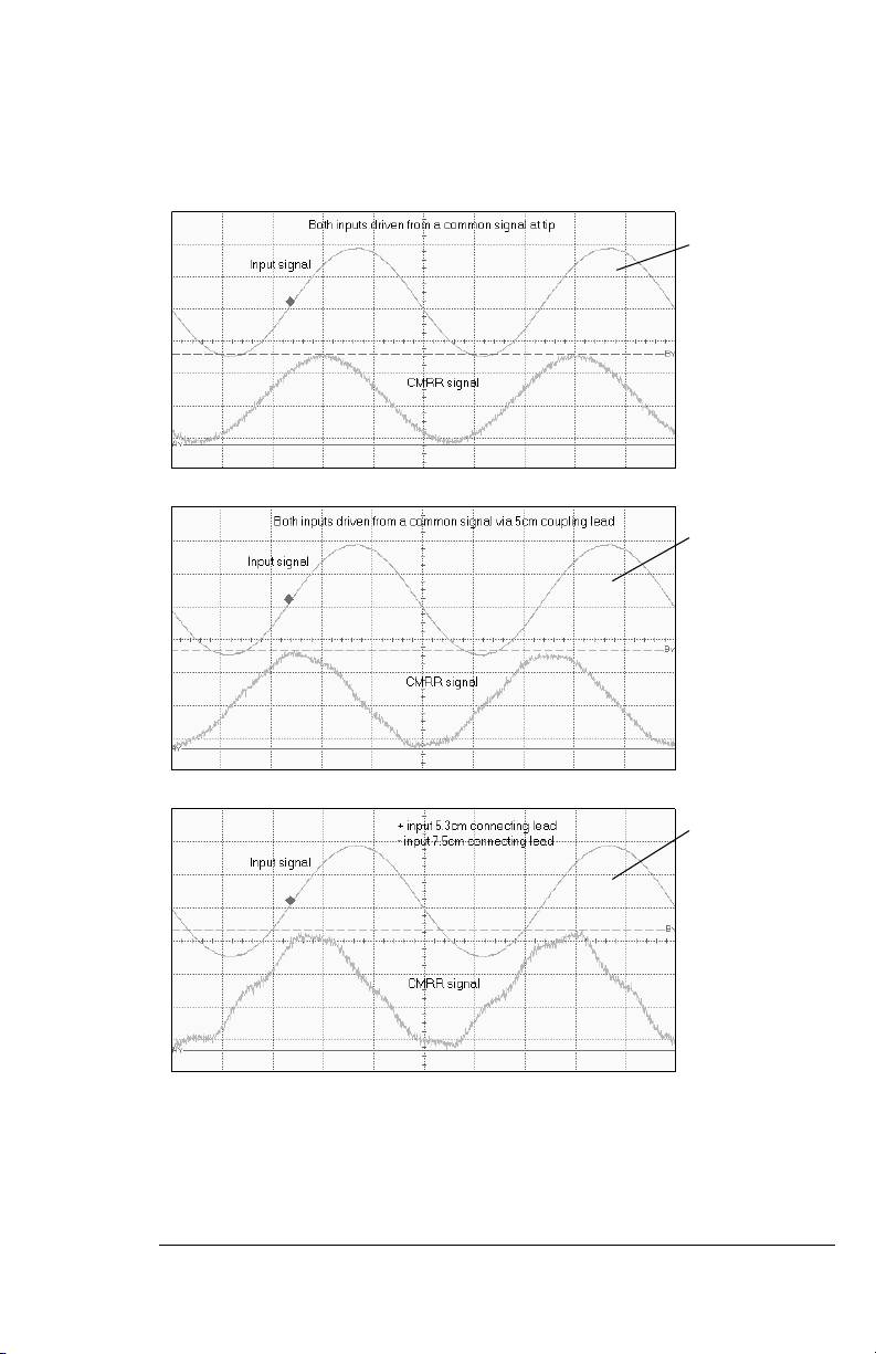
The method you use to connect the probe to the circuit under test is critical for
ensuring accurate measurements. The following examples examine the effect of
using different lengths of wire at 100MHz to connect the signal source to the
probe tip.
The Impedance of the Source
This is another instance where the symmetry of the differential circuit is
important. The impedance of the source forms a network with the input
impedance of the connection and the probe. This network determines the
frequency response for the measurement. If each side of the differential source
has a different impedance, the frequency response of each side will be different.
This lack of balance is reflected in reduced CMRR. The higher the impedance
of the source, the more critical these parasitic effects.
The Ground Connection
A poorly located ground connection allows ground loops to add to the common
mode signal. The differential probe measures the potential difference between
two locations on a PC board. Usually, it is not necessary to ground the probe.
Whether to ground the probe depends on the magnitude and frequency of the
voltage difference between the oscilloscope ground and the board ground. It is
good practice to maintain a board ground. Without this ground reference, you
could easily exceed the common mode range of the probe.
Probe Offset
The amplifiers in the 1159A probe limit the Differential Mode Range to 400mV.
If the input to the probe is approaching 400mV, there is little offset range available
for positioning the trace on screen. There are two solutions to this problem:
• Attenuate the signal into the probe with the 1/10 or 1/20 attenuator. This
mode of operation will induce some small loss in CMRR.
•Use Position to position the trace on screen.
The added feature of position control independent of Offset allows trace
positioning without calculating how much probe offset range is available. The
trace can be positioned by dragging the trace or positioning the trace under the
Probe menu.
12
1159A 1GHz Active Differential Probe
To Connect the Probe to the Circuit under Test
Both inputs derived
from a common signal
at probe tip.
CMRR = 35.6dB
Both inputs derived
from a common signal
via 5cm coupling lead.
CMRR = 35dB
Probe coupli ng leads
of different length.
Positive input 5.3cm.
Negative input 7.5cm.
CMRR = 33dB
13

1159A 1GHz Active Differential Probe
Recommended Probe Configurations
Recommended Probe Configurations
For best performance, use the following configurations. They are presented in
the recommended order from the most desirable to the least.
Note The use of the ground connection is optional for all configurations.
Direct Connection
1159A Probe Tip
Test Point Layout
See the “Test Point
Layout” section for
more information
AC Adapter/Attenuator
Use the attenuator shipped with the probe and marked with the same serial
number for accurate measurements. Do not use the attenuators with other
probes.
1159A Attenuator
Div-By-10 1 GHz
Div-By-20 1 GHz
1159A AC Coupler
Always Install Last
Test Point Layout
See the “Test Point
Layout” section for
more information
14
 Loading...