


HP 8491A/B, 8492A, 8493A/B/C,
11581A, 11582A and 1 1583A/C
Coaxial Attenuators
Product Overview
dc to 26.5 GHz
• High accuracy
• Low SWR
• Broadband frequency coverage
• Small size
Description
Hewlett-Packard coaxial fixed
attenuators provide precision
attenuation, flat frequency response,
and low SWR over broad frequency
ranges (dc to 26.5 GHz) at low prices.
Attenuators are available in eight
attenuation values: 3, 6, 10, 20, 30,
40, 50, and 60 dB; with performances
specified from dc to 26.5 GHz; and
with choice of four connector types:
Type-N, APC-7, SMA
1
, and APC 3.52.
These attenuators are all tested on
a state-of-the-art HP precision analyzer to assure specifications over
the full frequency ranges. Although
the HP 8493C is not specified above
26.5 GHz, it performs resonance
free to 34 GHz with only a small
loss in performance.
These connectors are stainless steel
for long wear and high repeatability.
The HP 8492A is furnished with
Amphenol precision 7 mm
connectors (APC-7). These sexless
connectors have a clearly defined
reference plane for precise and
unambiguous measurements.
The HP 8493A/B attenuators are
furnished with SMA type connectors.
The connectors are heat treated
beryllium copper for greater
strength and wear.
The HP 8493C is furnished with
the APC 3.5 connector which is
compatible with standard SMA
connectors but is more rugged and
offers improved repeatability over
hundreds of connections.
Precision construction
The attenuators employ a film on
an attenuator card as the resistive
element. The uniformity and repeatability of the film deposition process
result in high accuracy and low SWR
over very wide frequency ranges.
The HP 8493C features thin-filmtantalum nitride on a sapphire
substrate for exceptional precision
performance to 26.5 GHz. In fact, it
performs resonance-free to 34 GHz,
the top frequency limit of the
APC-3.5 connector.
The choice of connector type and
material also ensure accurate and
repeatable attenuation. The
HP 8491A/B attenuators are
furnished with Type-N connectors
whose dimensions are compatible
with either MIL-C-71 or MIL-C39012 connector specifications.
1. As per USASI Committee C83.2 compatible
with OSM, ARM, WPM, BRM, NPM, etc.
2. Mate with MIL-C-71 or MIL-C-39012
connectors.
HP 8493C
HP 8493A/B
HP 8492AHP 8491A/B
2
Description (cont’d)
Quality assurance in testing
The flat frequency response and low
SWR of the attenuators are assured
over the entire frequency range by
full frequency band testing on a
state-of-the-art HP precision
analyzer. Full frequency band
testing ensures that narrow resonances in the frequency band are
not overlooked. Actual attenuation
values taken at dc, 4, 8, 12, 18, and
26.5 GHz are stamped on the
attenuator body for permanent and
easy reference.
Testing each attenuator with a
state-of-the-art HP precision analyzer brings standards lab accuracy
to production testing because the
system can determine its own
measurement uncertainties and
compensate for them in the testing
process. System calibration is derived
from precise physical standards
which are directly traceable to the
National Bureau of Standards. In
addition, automatic testing eliminates
the possibility of human error in
setting instrument controls, taking
data, or making calculations.
Applications
Ruggedness, reliability and small
size make these attenuators useful
both on the bench and in systems
applications. With their high accuracy
and low SWR they are ideally suited
for extending the range of sensitive
power meters for higher power
measurements and for “padding”
poorly matched devices to improve
system SWR.
These same characteristics lend
themselves to applications as calibration standards in attenuation
and RF substitution measurements.
With their broad dc to 26.5 GHz
frequency range and reasonable
cost, general applications, such as
the reduction of power level to
sensitive components and instrumentation systems, are attractive
and appropriate uses for these
attenuators.
Accuracy
The accuracy of an attenuator
directly affects the accuracy of the
measurement where the attenuator
is used. In fact, attenuators are
used extensively as the standard
against which other instruments or
devices are calibrated.
HP’s fixed attenuators achieve flat
frequency response (typically a few
hundredths of a dB) and overall
accuracy (typically ±2 % of value
in dB at 26.5 GHz) through the use
of thin-film attenuator cards. These
cards are composed of high stability
tantalum nitride resistive film
deposited on a sapphire or alumina
substrate.
Quality assurance
in specifications
The following examples demonstrate
the reliability and comprehensiveness
of specifications. Although the absolute accuracy for a 3-dB attenuator
is specified as ±0.3 dB, test data
statistics indicate an expected
value of 3 dB ±0.20 dB from dc to
18 GHz. Similarly a 30-dB attenuator is specified as ±1.0 dB, but
typically is no worse than 30 dB
±0.75 dB from dc to 18 GHz. The
other attenuation values are also
specified as conservatively.
In addition, Hewlett-Packard
precision attenuators meet more
comprehensive performance standards. Linear phase response is an
example. Not only is wide bandwidth
significant, but also linear phase
response is an important parameter
for applications where pulse distortion
must be kept to a minimum. The
excellent linearity of the HP attenuators is typified in the accompanying illustration of an actual network
analyzer measurement.
Economy
Automated procedures have resulted
in economies of scale in production
and testing. The automated resistive
film deposition process permits
high-volume manufacture with
excellent yield. Furthermore,
characteristics are consistently
uniform; hand “touch-up” is not
required to meet specifications.
Automatic testing means exceptionally thorough, high-accuracy measurements can be performed in
appreciably shorter time than could
be done manually.
The overall result is outstanding
attenuator performance at
attractive prices.
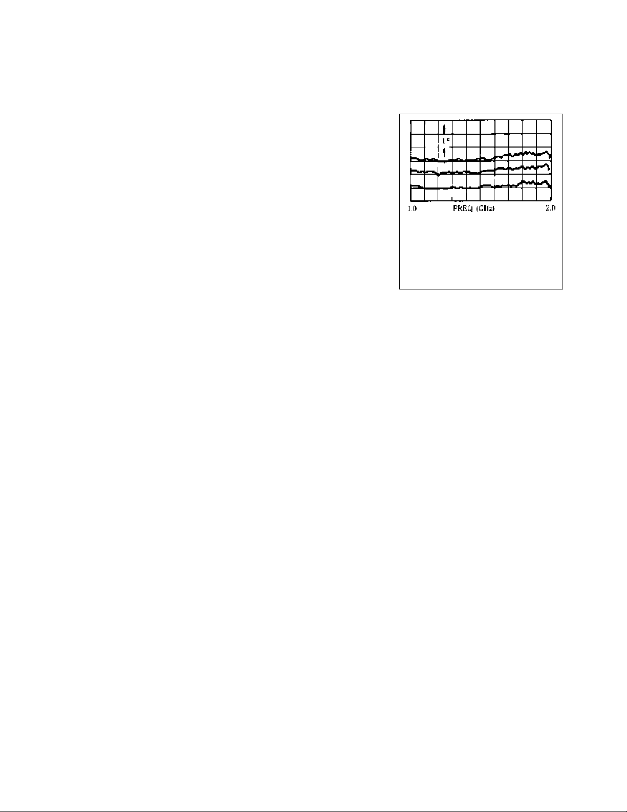
Center trace is phase response of HP 8491A
–6 dB attenuator from 1.0 to 2.0 GHz taken
with HP 8410 network analyzer. Top and
bottom traces are ±1° calibration. Linear
phase component has been compensated for
with a line stretcher. Response, therefore,
shows nonlinear phase deviation of < ± 1/2°
over 1 to 2 GHz band.
 Loading...