

Page 1

Keysight V8486A
Power Sensor
User’s Guide
Page 2

Notices
Copyright Notice
© Keysight Technologies 1999-2018
No part of this manual may be reproduced in
any form or by any means (including electronic
storage and retrieval or translation into a foreign language) without prior agreement and
written consent from Keysight Technologies as
governed by United States and international
copyright laws.
Manual Part Number
08486-90131
Edition
Edition 6, March 1, 2018
Printed in:
Printed in Malaysia
Published by:
Keysight Technologies
Bayan Lepas Free Industrial Zone,
11900 Penang, Malaysia
Technology Licenses
The hard ware and/or software described in
this document are furnished under a license
and may be used or copied only in accordance
with the terms of such license.
Declaration of Conformity
Declarations of Conformity for this product
and for other Keysight products may be downloaded from the Web. Go to http://www.key-
sight.com/go/conformity. You can then search
by product number to find the latest Declaration of Conformity.
U.S. Government Rights
The Software is “commercial computer software,” as defined by Federal Acquisition Regulation (“FAR”) 2.101. Pursuant to FAR 12.212
and 27.405-3 and Department of Defense FAR
Supplement (“DFARS”) 227.7202, the U.S.
government acquires commercial computer
software under the same terms by which the
software is customarily provided to the public.
Accordingly, Keysight provides the Software to
U.S. government customers under its standard
commercial license, which is embodied in its
End User License Agreement (EULA), a copy of
which can be found at http://www.key-
sight.com/find/sweula. The license set forth in
the EULA represents the exclusive authority by
which the U.S. government may use, modify,
distribute, or disclose the Software. The EULA
and the license set forth therein, does not
require or permit, among other things, that
Keysight: (1) Furnish technical information
related to commercial computer software or
commercial computer software documentation that is not customarily provided to the
public; or (2) Relinquish to, or otherwise provide, the government rights in excess of these
rights customarily provided to the public to
use, modify, reproduce, release, perform, display, or disclose commercial computer software or commercial computer software
documentation. No additional government
requirements beyond those set forth in the
EULA shall apply, except to the extent that
those terms, rights, or licenses are explicitly
required from all providers of commercial
computer software pursuant to the FAR and
the DFARS and are set forth specifically in
writing elsewhere in the EULA. Keysight shall
be under no obligation to update, revise or
otherwise modify the Software. With respect
to any technical data as defined by FAR 2.101,
pursuant to FAR 12.211 and 27.404.2 and
DFARS 227.7102, the U.S. government
acquires no greater than Limited Rights as
defined in FAR 27.401 or DFAR 227.7103-5 (c),
as applicable in any technical data.
Warranty
THE MATERIAL CONTAINED IN THIS DOCUMENT IS PROVIDED “AS IS,” AND IS SUBJECT
TO BEING CHANGED, WITHOUT NOTICE, IN
FUTURE EDITIONS. FURTHER, TO THE MAXIMUM EXTENT PERMITTED BY APPLICABLE
LAW, KEYSIGHT DISCLAIMS ALL WARRANTIES, EITHER EXPRESS OR IMPLIED, WITH
REGARD TO THIS MANUAL AND ANY INFORMATION CONTAINED HEREIN, INCLUDING
BUT NOT LIMITED TO THE IMPLIED WARRANTIES OF MERCHANTABILITY AND FITNESS
FOR A PARTICULAR PURPOSE. KEYSIGHT
SHALL NOT BE LIABLE FOR ERRORS OR FOR
INCIDENTAL OR CONSEQUENTIAL DAMAGES
IN CONNECTION WITH THE FURNISHING,
USE, OR PERFORMANCE OF THIS DOCUMENT OR OF ANY INFORMATION CONTAINED
HEREIN. SHOULD KEYSIGHT AND THE USER
HAVE A SEPARATE WRITTEN AGREEMENT
WITH WARRANTY TERMS COVERING THE
MATERIAL IN THIS DOCUMENT THAT CONFLICT WITH THESE TERMS, THE WARRANTY
TERMS IN THE SEPARATE AGREEMENT
SHALL CONTROL.
Safety Information
CAUTION
A CAUTION notice denotes a hazard. It calls
attention to an operating procedure, practice,
or the like that, if not correctly performed or
adhered to, could result in damage to the
product or loss of important data. Do not proceed beyond a CAUTION notice until the indicated conditions are fully understood and met.
WARNING
A WARNING notice denotes a hazard. It calls
attention to an operating procedure, practice,
or the like that, if not correctly performed or
adhered to, could result in personal injury or
death. Do not proceed beyond a WARNING
notice until the indicated conditions are fully
understood and met.
2 Keysight V8486A User’s Guide
Page 3

Certification
Warranty
Keysight Technologies certifies that this product met its published specifications at the time of
shipment. Keysight further certifies that its calibration measurements are traceable to the United
States National Institute of Standard and Technology (formerly National Bureau of Standards), to
the extent allowed by that organization’s calibration facility, and to the calibration facilities of other
International Standards Organization members.
This Keysight Technologies instrument product is warranted against defects in material and
workmanship for a period of 3 years from date of shipment. During the warranty period, Keysight
Technologies will at its option, either repair or replace products which prove to be defective. For
warranty service or repair, this product must be returned to a service facility designated by
Keysight Technologies. Buyer shall prepay shipping charges to Keysight Technologies and Keysight
Technologies shall pay shipping charges, duties, and taxes for products returned to Keysight
Technologies from another country. Keysight Technologies warrants that its software and firmware
designated by Keysight Technologies for use with an instrument will execute its programming
instructions when properly installed on that instrument. Keysight Technologies does not warrant
that the operation of the instrument, or firmware will be uninterrupted or error free.
Limitation of Warranty
The foregoing warranty shall not apply to defects resulting from improper or inadequate
maintenance by Buyer, Buyer-supplied software or interfacing, unauthorized modification or
misuse, operation outside of the environmental specifications for the product, or improper site
preparation or maintenance. NO OTHER WARRANTY IS EXPRESSED OR IMPLIED. KEYSIGHT
TECHNOLOGIES SPECIFICALLY DISCLAIMS THE IMPLIED WARRANTIES OF MERCHANTABILITY
AND FITNESS FOR A PARTICULAR PURPOSE.
Keysight V8486A User’s Guide
3
Page 4

Exclusive Remedies
THE REMEDIES PROVIDED HEREIN ARE BUYER’S SOLE AND EXCLUSIVE REMEDIES. KEYSIGHT
TECHNOLOGIES SHALL NOT BE LIABLE FOR ANY DIRECT, INDIRECT, SPECIAL, INCIDENTAL, OR
CONSEQUENTIAL DAMAGES, WHETHER BASED ON CONTRACT, TORT, OR ANY OTHER LEGAL
THEORY.
Safety Considerations
Read the information below before using this instrument.
The following general safety precautions must be observed during all phases of operation, service,
and repair of this instrument. Failure to comply with these precautions or with specific warnings
elsewhere in this manual violates safety standards for design, manufacture, and intended use of
the instrument. Keysight Technologies assumes no liability for the customer’s failure to comply
with these requirements.
4 Keysight V8486A User’s Guide
Page 5

Environmental Conditions
The V8486A is designed for indoor use and in an area with low condensation. The table below
shows the general environmental requirements for this instrument.
Environmental condition Requirement
Temperature
Humidity
Altitude
Operating condition
– 0 °C to 55 °C
Storage condition
– –40 °C to 70 °C
Operating condition
– Up to 95%
Storage condition
– Up to 95% RH at 40°C (non-condensing)
Operating condition
– Up to 4550 meters
Storage condition
– Up to 7,600 meters
Keysight V8486A User’s Guide 5
Page 6

Waste Electrical and Electronic Equipment (WEEE) Directive 2002/96/EC
This instrument complies with the WEEE Directive (2002/96/EC) marking requirement. This affixed
product label indicates that you must not discard this electrical or electronic product in domestic
household waste.
Product category:
With reference to the equipment types in the WEEE directive Annex 1, this instrument is classified
as a “Monitoring and Control Instrument” product.
The affixed product label is as shown below.
Do not dispose in domestic household waste.
To return this unwanted instrument, contact your nearest Keysight Service Center, or visit http://
about.keysight.com/en/companyinfo/environment/takeback.shtml for more information.
Sales and Technical Support
To contact Keysight for sales and technical support, refer to the support links on the following
Keysight websites:
– www.keysight.com/find/waveguidepowersensors
(product-specific information and support, software and
documentation updates)
– www.keysight.com/find/assist
(worldwide contact information for repair and service)
6 Keysight V8486A User’s Guide
Page 7

Table of Contents
Certification . . . . . . . . . . . . . . . . . . . . . . . . . . . . . . . . . . . . . . . . . . . . . . . . . . . . . . . . . . . . 3
Warranty . . . . . . . . . . . . . . . . . . . . . . . . . . . . . . . . . . . . . . . . . . . . . . . . . . . . . . . . . . . . . . 3
Limitation of Warranty . . . . . . . . . . . . . . . . . . . . . . . . . . . . . . . . . . . . . . . . . . . . . . . . . . . 3
Exclusive Remedies . . . . . . . . . . . . . . . . . . . . . . . . . . . . . . . . . . . . . . . . . . . . . . . . . . . . . 4
Safety Considerations . . . . . . . . . . . . . . . . . . . . . . . . . . . . . . . . . . . . . . . . . . . . . . . . . . . . 4
Environmental Conditions . . . . . . . . . . . . . . . . . . . . . . . . . . . . . . . . . . . . . . . . . . . . . . . . 5
Waste Electrical and Electronic Equipment (WEEE) Directive 2002/96/EC . . . . . . . . . . 6
Product category: . . . . . . . . . . . . . . . . . . . . . . . . . . . . . . . . . . . . . . . . . . . . . . . . . . . . 6
Sales and Technical Support . . . . . . . . . . . . . . . . . . . . . . . . . . . . . . . . . . . . . . . . . . . . . . 6
1Introduction
General Information . . . . . . . . . . . . . . . . . . . . . . . . . . . . . . . . . . . . . . . . . . . . . . . . . . . . 10
Warranty . . . . . . . . . . . . . . . . . . . . . . . . . . . . . . . . . . . . . . . . . . . . . . . . . . . . . . . . . . 10
Description . . . . . . . . . . . . . . . . . . . . . . . . . . . . . . . . . . . . . . . . . . . . . . . . . . . . . . . . . 10
Accessories . . . . . . . . . . . . . . . . . . . . . . . . . . . . . . . . . . . . . . . . . . . . . . . . . . . . . . . . 11
Recommended calibration interval . . . . . . . . . . . . . . . . . . . . . . . . . . . . . . . . . . . . . . 11
Installation . . . . . . . . . . . . . . . . . . . . . . . . . . . . . . . . . . . . . . . . . . . . . . . . . . . . . . . . . . . 12
Initial inspection . . . . . . . . . . . . . . . . . . . . . . . . . . . . . . . . . . . . . . . . . . . . . . . . . . . . . 12
Interconnections and calibration . .
age and Shipment . . . . . . . . . . . . . . . . . . . . . . . . . . . . . . . . . . . . . . . . . . . . . . . . . . 13
Stor
Original packaging . .
. . . . . . . . . . . . . . . . . . . . . . . . . . . . . . . . . . . . . . 12
. . . . . . . . . . . . . . . . . . . . . . . . . . . . . . . . . . . . . . . . . . . . . . . . . 13
2 General Operation
Operation . . . . . . . . . . . . . . . . . . . . . . . . . . . . . . . . . . . . . . . . . . . . . . . . . . . . . . . . . . . . 16
Operating precautions . . . . . . . . . . . . . . . . . . . . . . . . . . . . . . . . . . . . . . . . . . . . . . . . 16
Power meter calibrations . . . . . . . . . . . . . . . . . . . . . . . . . . . . . . . . . . . . . . . . . . . . .17
Power measurements . . . . . . . . . . . . . . . . . . . . . . . . . . . . . . . . . . . . . . . . . . . . . . . . 17
Operating instructions . . . . . . . . . . . . . . . . . . . . . . . . . . . . . . . . . . . . . . . . . . . . . . . . 19
Modulation effects . . . . . . . . . . . . . . . . . . . . . . . . . . . . . . . . . . . . . . . . . . . . . . . . . . . 19
Linearity correction . . . . . . . . . . . . . . . . . . . . . . . . . . . . . . . . . . . . . . . . . . . . . . . . . . 19
3 Specifications and Characteristics
Specifications and Characteristics . . . . . . . . . . . . . . . . . . . . . . . . . . . . . . . . . . . . . . . . . 22
Calibration Factor (C
4Service
Performance Tests . . . . . . . . . . . . . . . . . . . . . . . . . . . . . . . . . . . . . . . . . . . . . . . . . . . . . 26
Zero set performance verification . . . . . . . . . . . . . . . . . . . . . . . . . . . . . . . . . . . . . . . 26
Power linearity per
Replaceable Parts . . . . . . . . . . . . . . . . . . . . . . . . . . . . . . . . . . . . . . . . . . . . . . . . . . . . . . 30
Repair and adjustments . . . . . . . . . . . . . . . . . . . . . . . . . . . . . . . . . . . . . . . . . . . . . . . 30
F) . . . . . . . . . . . . . . . . . . . . . . . . . . . . . . . . . . . . . . . . . . . . . . . . . . 23
formance verification . . . . . . . . . . . . . . . . . . . . . . . . . . . . . . . . . . 27
Keysight V8486A User’s Guide 7
Page 8

List of Figures
List of Tables
Figure 1-1
Figure 2-1
Figure 2-2
Figure 4-1
Figure 4-2
Table 2-1 Cal factor . . . . . . . . . . . . . . . . . . . . . . . . . . . . . . . . . . . . . . . . . . . . . . . 18
Table 3-1
Table 4-1
Keysight V8486A power sensor with accessories and hardware
Precision V-band interface on the front of the power sensor . .
Typical influence of temperature on sensitivity . . . . . . . . . . . . . . . . .19
Zero set performance verification equipment setup . . . . . . . . . . . . . . 26
Power linearity performance verification equipment setup . . . . . . . . 28
Calibration factor uncertainty at 1 mW (0 dBm) . . . . . . . . . . . . . . . . . 23
Replaceable parts . . . . . . . . . . . . . . . . . . . . . . . . . . . . . . . . . . . . . . . . 30
. . . . 10
. . . . . 17
8 Keysight V8486A User’s Guide
Page 9

Keysight V8486A Power Sensor
User’s Guide
1 Introduction
General Information 10
Installation 12
Storage and Shipment 13
This chapter provides an overview of the V8486A power sensor and its general information.
9
Page 10

1Introduction
General Information
This User’s guide contains information about initial inspection and operation of the Keysight
V8486A power sensor.
Keysight V8486A
power sensor
Flange screws
(1390-0671)
Figure 1-1 Keysight V8486A power sensor with accessories and hardware
Warranty
The power sensor is warranted and certified as indicated on page 3 of this manual. Do not open
the power sensor. Any attempt to disassemble the power sensor will void warranty.
Description
The Keysight V8486A is a diode-based power sensor. It measures power levels in a range from –30
dBm to +20 dBm. (Specifications for the power sensor are in Table 3-1 .) The Keysight V8486A
measures at frequencies from 50 GHz to 75 GHz.
The power is determined from the ac voltage developed across the waveguide termination from the
microwave source. The diodes convert this ac voltage to dc. The dc voltage produced is
proportional to the square of the ac voltage. The dc voltage thus generated is a very low-level
voltage and requires amplification before it can be transferred via the sensor cable to the power
meter.
Hex ball driver
(8710-1539)
10
The amplification is provided by an input amplifier assembly which consists of a chopper (sampling
gate) and an input amplifier. The dc voltage is routed to the chopper circuit which converts the
Keysight V8486A User’s Guide
Page 11

Introduction 1
NOTE
CAUTION
ow-level dc voltage to an ac voltage. The chopper is driven by a square wave generated by the
l
power meter. The result is an ac output signal proportional to the dc input. The ac signal is then
amplified by the input amplifier. The relatively high-level ac signal output can now be routed by
standard cables.
The Keysight V8486A power sensor is compatible with the following power meters:
Keysight 435B Keysight E1416A
Keysight 436A Keysight E4418A/B
Keysight 437B Keysight E4419A/B
Keysight 438A Keysight 70100A
To obtain optimum accuracy for power measurements above +10 dBm, when used with the
Keysight E4418A and Keysight E4419A power meters, a firmware upgrade will be required. Refer
to your Keysight E4418A and Keysight E4419A power meter’s user’s guide for instructions on
how to obtain the revision of the firmware currently installed in the unit. The firmware revision
required is A1.03.00 (or above) for the Keysight E4418A and A2.03.00 (or above) for the Keysight
E4419A. Contact your local Keysight Technologies Sales and Service Office for more information.
In application, the power sensor is connected between a microwave source and a compatible
power meter. The power sensor provides a matched load for the microwave source for very low
SWR. The power meter indicates the power dissipated in the load in μW, mW or in dBm.
Do not disassemble the power sensor. The power sensor is extremely static-sensitive and can be
easily damaged.
Accessories
Included is a hex ball driver plus the waveguide mounting screws. Refer to Figure 1-1 for a visual
check of what should be included with your power sensor.
Recommended calibration interval
Keysight Technologies recommends a one-year calibration cycle for the V8486A power sensor.
Keysight V8486A User’s Guide
11
Page 12

1Introduction
Installation
Initial inspection
Inspect the shipping container for damage. If the shipping container or packaging material is
damaged, it should be kept until the contents of the shipment have been checked mechanically
and electrically. If there is mechanical damage or if the instrument does not pass the performance
tests, notify the nearest Keysight Technologies office. Keep the damaged shipping materials (if any)
for inspection by the carrier and a Keysight Technologies representative.
Interconnections and calibration
The Keysight V8486A power sensor has two inputs: a Type-N connector and a waveguide flange.
During calibration, the Type-N connector is connected to the calibration port of the power meter.
During measurement, the waveguide flange is connected to the device under test.
CAUTION
Connect the power sensor by turning only the nut on the Type-N connector. Damage can occur if
torque is applied to the power sensor body.
The waveguide flanges can be damaged if the flange screws are over-tightened. Do not fully
tighten one flange screw without tightening the one opposite. First insert screws and tighten
until finger tight. If you are using the hex ball driver, hold the driver between thumb and
forefinger while incrementally tightening screws opposite each other until reaching a maximum
torque of 0.42 N x m.
Use the protective packaging provided with the power sensor to protect it from dirt and
mechanical damage whenever it is not in use. Any burrs, dents or dirt on the flange or waveguide
surface will increase the SWR and change the Cal Factor.
Refer to the power meter operating and service manual for interconnecting instructions.
12
Keysight V8486A User’s Guide
Page 13

Storage and Shipment
Original packaging
Containers and materials identical to those used in factory packaging are available through
Keysight Technologies offices. If the instrument is being returned to Keysight Technologies for
servicing, attach a tag indicating the type of service required, return address, model number, and
serial number. Also, mark the container FRAGILE to assure careful handling. In any
correspondence, refer to the instrument by model number and serial number.
Introduction 1
Keysight V8486A User’s Guide
13
Page 14

1Introduction
THIS P
AGE HAS BEEN INTENTIONALLY LEFT BLANK.
14
Keysight V8486A User’s Guide
Page 15

Keysight V8486A Power Sensor
User’s Guide
2 General Operation
Operation 16
This chapter provides the V8486A general operation information on how to check and prepare your
instrument for operation.
15
Page 16

2 General Operation
Operation
Operating precautions
WARNING
BEFORE CONNECTING THE POWER SENSOR TO OTHER INSTRUMENTS, ensure that all
instruments are connected to the protective (earth) ground. Any interruption of the
protective earth grounding will cause a potential shock hazard that could result in personal
injury and cause damage to the power sensor.
CAUTION
If the following energy and power levels are exceeded, the power meter system may be
damaged.
– Maximum Average Power: 200 mW
– Maximum Peak Power: 40W
[a] 10 micro-second pulse, 0.5% duty cycle or equivalent such that 200 mW maximum average power and 40W peak power are not exceeded.
The power sensor has a precision machined V-band waveguide interface. The size and position of
the aperture, the alignment holes and pins, and the flatness of the mating faces are all very tightly
controlled. Refer to Figure 2-1.
In order to get the best possible measurement results the mating part must be of similar quality.
Connection to a V-band waveguide component in which the interface dimensions are not
accurately controlled can lead to increased SWR, inaccurate Cal Factor correction, and/or
repeatability problems. In addition, connections to a well-manufactured but dirty part can lead to
any of the above measurement problems. Conversely, always insuring connections to parts with
clean, high-quality waveguide interfaces will lead to accurate power measurements over the life of
the product.
[a]
CAUTION
16
Connection to a V-band waveguide component with a dirty, or damaged flange (for example
loose particulates, raised metal burrs or bent alignment pins) can damage the precision
interface of the power sensor. Always inspect and clean the mating part prior to connection.
Use the protective packaging provided with the sensor to protect the waveguide connector from
dirt and mechanical damage whenever it is not in use. Any burn, dents or dirt on the flange or
waveguide surface will increase the SWR and change the Cal Factor.
The Type-N connector plastic bead deteriorates when contacted by any chlorinated or aromatic
hydrocarbons such as acetone, trichlorethylene, carbon tetrachloride, benzene, etc. Clean the
connector face with a cotton swab saturated in isopropyl alcohol.
Keysight V8486A User’s Guide
Page 17

Figure 2-1 Precision V-band interface on the front of the power sensor
1.905
3.810
2× ø 1.588
ø 14.288
Bolt circle
2× ø 1.660
Units in mm
4× 4-40 UNC-2B
NOTE
Power meter calibrations
The procedure for calibration may be different for each compatible power meter. Follow the
calibration directions given in your power meter manual.
General Operation 2
Power measurements
To correct for varying responses at different frequencies a cal factor chart is included on the power
sensors. To use the cal factor at the frequency of interest, adjust the power meter's CAL FACTOR
control according to the instructions in the power meter's operating and service manual. This will
automatically correct the power readings.
If you are using a Keysight 435B or Keysight 436A, the minimum cal factor setting is 85% and the
maximum is 100%. If the cal factor setting for your frequency of interest is below the meter's
minimum or above the meter's maximum, set the cal factor control to 100%, and divide the reading
in watts units by the decimal equivalent of the cal factor. For example, if the cal factor is 75%,
divide the reading by 0.75. (This will result in a larger value of power than that displayed by the
meter.)
If the cal factor is 104%, divide the reading by 1.04. (This will result in a smaller value of power
than that displayed by the meter.)
If reading in dBm, use the chart in Table 2-1 to convert the cal factor to dB and add this value to
the reading. Interpolate for values between those shown. As above, the cal factor control should be
set to 100%. If the cal factor is 75%, add 1.25 dB to the displayed value. On the other hand, if the
cal factor is 104% subtract 0.17 dB from the displayed reading.
The above procedure has eliminated some mathematical steps; the following formula may be of
some use:
Correct dBm = Reading dBm – 10 × Log
{Cal Factor (decimal)}.
10
Keysight V8486A User’s Guide
17
Page 18

2 General Operation
Tab le 2-1 Cal factor
Cal factor dB Cal factor dB Cal factor dB
70% 1.549 85% 0.706 115% –0.607
71% 1.487 101% −0.043 116% −0.645
72% 1.427 102% −0.086 117% −0.682
73% 1.367 103% −0.128 118% −0.719
74% 1.308 104% −0.170 119% −0.755
75% 1.249 105% −0.212 120% –0.792
76% 1.192 106% −0.253 121% −0.828
77% 1.134 107% −0.294 122% −0.864
78% 1.079 108% −0.334 123% −0.899
79% 1.024 109% −0.374 124% −0.934
80% 0.969 110% −0.414 125% −0.969
81% 0.915 111% −0.453 126% −1.004
82% 0.862 112% −0.492 127% –1.038
83% 0.809 113% −0.531 128% –1.072
84% 0.757 114% −0.569 129% –1.106
130% –1.139
18
Keysight V8486A User’s Guide
Page 19
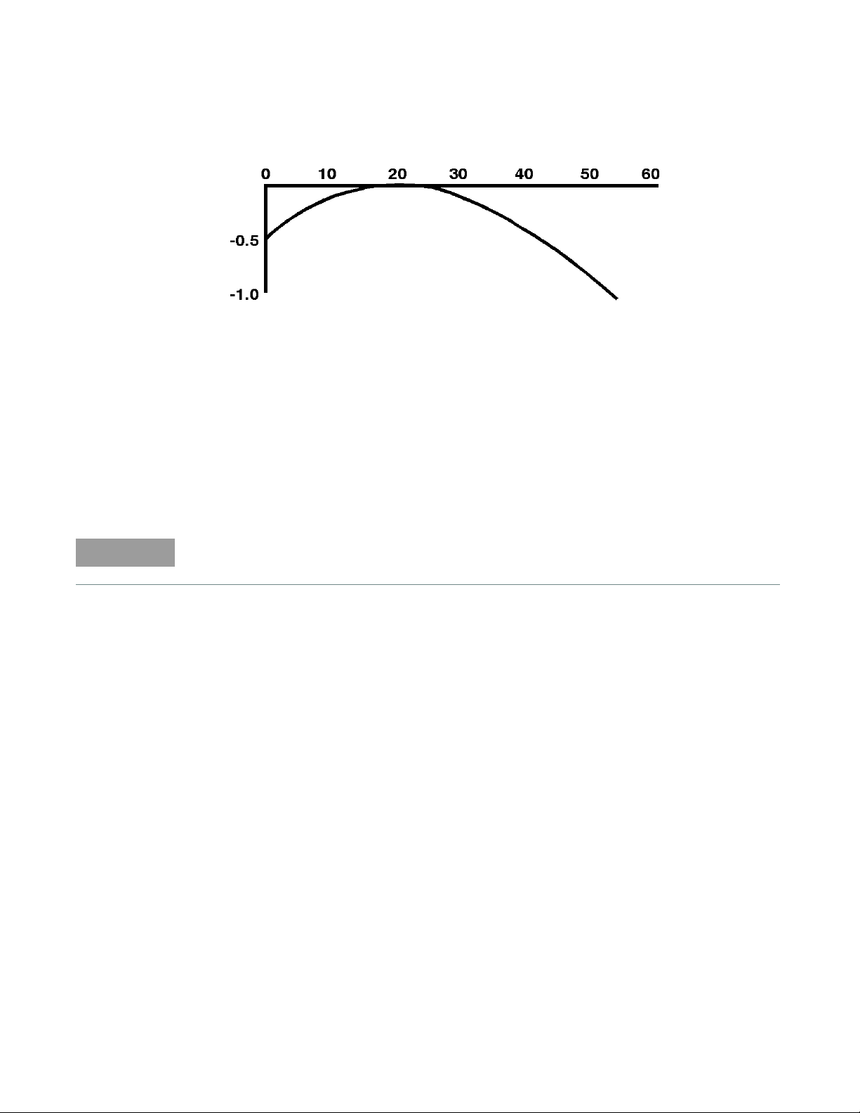
Figure 2-2 Typical influence of temperature on sensitivity
Sensitivity change, dB
Temperature, °C
NOTE
The sensitivity of the power sensor is influenced by ambient temperature. The sensor should be
calibrated at the temperature of operation to obtain the most accurate results. Typical temperature
sensitivity variations are shown in Figure 2-2.
Operating instructions
General Operation 2
To operate the power sensor, refer to the operating instructions in of the power meter operating
and service manual.
If having an open RF connection on your system is a concern, terminate the sensor Type-N
calibration port with a 50 Ω load.
Modulation effects
When measuring microwave sources that are modulated at the chopper frequency (nominally 220
Hz for the Keysight 43X family and 217 Hz for the Keysight E4418A/B and Keysight E4419A/B), or
at the first or second harmonic or submultiples of the chopper frequency, beat notes will occur.
Unless the modulation rate is exactly the chopper frequency, they can usually be eliminated by
averaging since the amplitudes are centered on the actual power. These frequencies may also be
avoided by changing the modulation frequency slightly, if possible.
If you are using a Keysight 437B, Keysight E4418A/B or Keysight E4419A/B Power Meter, a filter
setting of 128 will minimize most beat note interference. To minimize beat note interference using
a Keysight 438A Power Meter select a filter number of at least 7.
Linearity correction
For most Keysight 8480 series power sensors the correct (A type or D type) linearity correction
table is automatically selected. However, when you use the Keysight V8486A power sensor with
Keysight EPM power meters, you must override the automatic selection and select the D-type
correction. This procedure provides optimum accuracy when making power measurements
>+10dBm. Subsequent connection of another
Keysight V8486A User’s Guide
A-type sensor will result in a warning message stating the “Linearity Override May be Required”.
To select the linearity type to be applied:
19
Page 20

2 General Operation
Keysight E4418B
Press [System Inputs], Tables, Linearity ATyp DTyp.
Keysight E4419B
Press [System Inputs], Tables, A Linearity ATyp DTyp or B Linearity ATyp DTyp.
NOTE
For use with the Keysight E4418A and Keysight E4419A power meters, a firmware upgrade will
be required. Refer to your Keysight E4418A and Keysight E4419A power meter’s user’s guide for
instructions on how to obtain the revision of the firmware currently installed in the unit. The
firmware revision required is A1.03.00 (or above) for the Keysight E4418A and A2.03.00 (or
above) for the Keysight E4419A. Contact your local Keysight Technologies Sales and Service
Office for further information.
20
Keysight V8486A User’s Guide
Page 21

Keysight V8486A Power Sensor
User’s Guide
3 Specifications and
Characteristics
Specifications and Characteristics 22
Calibration Factor (CF) 23
21
Page 22

3 Specifications and Characteristics
Specifications and Characteristics
For the characteristics and specifications of the V8486A Power Sensor, refer to the datasheet at
https://literature.cdn.keysight.com/litweb/pdf/5991-3676EN.pdf.
22
Keysight V8486A User’s Guide
Page 23

Calibration Factor (CF)
The CAL FACTOR compensates for the frequency response of the sensor. CAL FACTOR data is
provided on a label attached to the sensor cover. Uncertainties of the CAL FACTOR data are listed
in Table 3-1. ISO expanded uncertainties are calculated based on an NIST-traceable transfer
standard and an analysis of factory test system uncertainties. To use CAL FACTOR data during
power measurements, see “Power measurements” on page 17.
Table 3-1 Calibration factor uncertainty at 1 mW (0 dBm)
Specifications and Characteristics 3
Frequency (GHz)
50 4.8
51 6.1
52 5.9
53 5.9
54 5.9
55 4.6
56 6.1
57 6.1
58 6.2
59 6.2
60 4.7
61 6.2
62 6.1
63 6
64 6
65 4.5
66 6.6
ISO expanded uncertainty %
[a]
(coverage factor k=2)
[a] Refer to Application Note 64-1A: Keysight literature number 5965-6630E, “Fundamentals of RF and Microwave
Power Measurements” for more information regarding ISO expanded uncertainty.
Keysight V8486A User’s Guide
67 6.7
68 6.7
69 6.6
70 4.4
71 6.7
72 6.8
73 7.0
74 7.3
75 5.1
23
Page 24

3 Specifications and Characteristics
THIS P
AGE HAS BEEN INTENTIONALLY LEFT BLANK.
24
Keysight V8486A User’s Guide
Page 25

Keysight V8486A Power Sensor
User’s Guide
4 Service
Performance Tests 26
Replaceable Parts 30
This chapter provides information on the V8486A performance tests and service.
25
Page 26

4Service
Performance Tests
This section does not establish SWR test procedures since there are several test methods and
different equipment available for testing the SWR or reflection coefficient. Therefore, the actual
accuracy of the test equipment, all source match corrections, and all harmonics must be
accounted for when measuring against instrument specifications to determine a pass or fail
condition.
To measure the SWR across the waveguide band, use a directional coupler and detector selected
for the band of interest. The directional coupler should have a directivity greater than 36 dB, such
as the Keysight V752C/D. The detector should have greater than 0.4 mV/μW sensitivity and should
be calibrated with a rotary vane attenuator with an accuracy of 2%. Incident power should be less
than +20 dBm. A convenient source is a frequency multiplier driven by a Keysight 8360 B-Series
swept signal generator.
To check the calibration factor, the power sensor should be compared with another recently
calibrated power sensor. The source should be leveled with a reference coupler that has low SWR
and high directivity to monitor or level the incident power.
For calibration factor and error analysis we suggest Keysight Application Note 64-1A: Keysight
literature number 5965-6630E, "Fundamentals of RF and Microwave Power Measurements".
Zero set performance verification
This performance verification is carried out to verify that a minimal amount of residual offset error is
present after zeroing has been performed. The offset error is caused by contamination from several
sources including the noise of the device-under-test (DUT) itself. Zero set is the difference between
the power levels indicated by the DUT, after executing zeroing and the true zero power. Ideally, this
difference should be zero.
This performance test requires a compatible Keysight power meter with the DUT and a computer
with the Keysight IO Libraries Suite installed.
System specification : ±200 nW (for V/W8486A), tested at 50 MHz
Recommended power meter : EPM (N1913A/ 14A, E4418B/ 19B), EPM-P
Procedure
1 Connect the DUT (V/W8486A) to the power meter as shown in Figure 4-1.
(E4416A/ 17A), and P-series (N1911A/ 12A)
power meters
26
DUT
Figure 4-1 Zero set performance verification equipment setup
Keysight V8486A User’s Guide
Page 27

Service 4
2 Warm up the DUT for approximately 30 minutes.
3 Launch the Interactive IO on the Keysight IO Libraries Suite to send SCPI commands to the
DUT.
4 Reset the power meter to a known state by sending "*RST" command, followed by
"SYST:PRES" command to pre-set the meter's output to default value.
5 Connect the DUT to the power meter 1 mW calibrator and perform zeroing for the DUT by
sending "CAL:ZERO:AUTO ONCE". (Use the recommended adapter for respective model)
6 Perform calibration for the DUT by sending "CAL:AUTO ONCE".
7 Set the frequency of the DUT to 50 MHz by sending "FREQ 50MHz".
8 Enable auto-averaging for the DUT by sending "AVER:COUN:AUTO ON".
9 Change the power measurement unit of the DUT to watt by sending "UNIT:POW W".
10 Disconnect the DUT from the power meter 1 mW calibrator.
11 Perform zeroing for the DUT by sending "CAL:ZERO:AUTO ONCE".
12 Set the DUT to the single trigger mode by sending "INIT:CONT OFF".
13 Read the noise level of the DUT by sending "READ" and then record the reading.
14 Repeat step 13 for 10 times and then calculate the mean value of the readings.
15 Compare the calculated mean value to the system specification. If the test fails, refer to “Repair
and adjustments” on page 30.
Power linearity performance verification
The power linearity performance verification measures the relative linearity error of the V/W8486A.
All measurements are performed at 50 MHz. The reference power level for the linearity
measurement is 0 dBm for the V8486A and W8486A.
This performance verification requires the following equipment:
– signal generator (N5182A)
– thermocouple-based average power sensor, as a reference sensor (N8481A/5A/7A)
– power meter (E4416/7A)
– power splitter (11667A)
–amplifier
– step attenuators (8494H and 8496H)
– attenuator/switch driver (11713B)
Procedure
1 Turn on the signal generator and power meter (with the reference sensor connected). Connect
the DUT (V/W8486A) to the power meter. Allow them to warm up for approximately an hour.
2 Zero and calibrate the DUT using the reference sensor with the power meter.
3 Connect the power splitter to the RF output of the signal generator. The equipment setup is as
shown in Figure 4-2.
Keysight V8486A User’s Guide
27
Page 28

4Service
Amplifier
Signal generator
10 dB step attenuator
1 dB step attenuator
Power splitter
CAUTION
DUT
Power meter
Reference
sensor
Attenuator/
switch driver
(Optional)
Figure 4-2 Power linearity performance verification equipment setup
4 Set the continuous wave signal frequency of the signal generator, DUT, and reference sensor to
50 MHz. Set DUT to AVERAGE ONLY mode.
5 Start tuning the signal generator and/or attenuator/switch driver (optional) until the DUT
measures the power level as close as 0 dBm. Record the values as P
at 0 dBm and P
DUT
ref
at 0
dBm.
Do not exceed the maximum input power (27 dBm) of the power splitter to avoid damage to
the power splitter.
6 Record the power measured by the power meter for both DUT and reference power sensor as
as P
P
DUT
7 Normalize both P
respectively.
ref
DUT
and P
to the power measured at 0 dBm, based on the following
ref
equation.
Normalization Measured power (P
DUT/ref
) Measured power at 0 dBM (P
DUT/ref at 0 dBm
)+=
28
8 Calculate the linearity error of the DUT for the power level using the following equations.
Linearity error (dB) [P
Linearity error (%) Antilog
]
DUT
norm to 0 dBm
[P
--------------------------------------------------------------------------------------------
]
DUT
norm to 0 dBm
[P
–=
]
ref
norm to 0 dBm
[P
–
ref
10
]
norm to 0 dBm
×=
1– 100
9 Compare and record the calculated linearity error against the system linearity error
specifications.
Keysight V8486A User’s Guide
Page 29

Service 4
System linearity error specification DUT error2Ref sensor error
2
+=
System linearity error specification (2%)2(0.8%)
2
+2.07%±==
10 Repeat step 6 to step 9 by sweeping through the warranted power levels for power linearity test
as in the datasheet at 50 MHz.
11 Repeat step 5 to step 11 for normal mode. If the verification fails, refer to “Repair and
adjustments” on page 30.
12 The linearity system specification is calculated using the root sum of the squares (RSS) method
by considering the error caused from reference sensor used and the DUT error in the system at
50 Mhz. The error specification caused by the reference sensor and the DUT can be found in
their respective datasheet. The RSS error specification calculation is computed by using
following equation.
Example for the DUT measured at 50 Mhz, 20 dBm:
– DUT used is V8486A
– Reference sensor used is N8481A
Keysight V8486A User’s Guide
29
Page 30

4Service
Replaceable Parts
The part numbers of the hex ball driver and the hardware are listed in Figure 1-1. In addition, the
following protective parts are replaceable:
Tab le 4-1 Replaceable parts
Part number Description Usage
1401-0214 protective cap Type-N connector
08486-40103 protective cover V-band waveguide flange
There are no other replaceable parts for this product.
Repair and adjustments
Do not attempt to repair or adjust the power sensor. Due to the extreme static sensitivity of the
power sensor, customer repair is not recommended. If your power sensor should fail or need
calibration, return it to Keysight Technologies.
CAUTION
Do not disassemble the power sensor. The power sensor is extremely static sensitive and
can be easily damaged. If the power sensor shows evidence of attempted customer repair,
the warranty may be voided.
30
Keysight V8486A User’s Guide
Page 31

Page 32

This information is subject to change
without notice. Always refer to the
English version at the Keysight
website for the latest revision.
© Keysight Technologies 1999-2018
Edition 6, March 1, 2018
Printed in Malaysia
*08486-90131*
08486-90131
www.keysight.com
 Loading...