

Page 1

Keysight U7228A/C/F USB
Pre-Amplifier
Operating and
Service Manual
Page 2

Notices
CAUTION
WARNING
Copyright Notice
© Keysight Technologies 2015
No part of this manual may be repro-
duced in any form or by any means
(including electronic storage and
retrieval or translation into a foreign
language) without prior agreement and
written consent from Keysight Technologies as governed by United States and
international copyright laws.
Manual Part Number
U7228-90001
Edition
Edition 1, Feb 1, 2016
Printed in:
Printed in Malaysia
Published by:
Keysight Technologies
Bayan Lepas Free Industrial Zone,
11900 Penang, Malaysia
Technology Licenses
The hard ware and/or software
described in this document are furnished under a license and may be
used or copied only in accordance with
the terms of such license.
Declaration of Conformity
Declarations of Conformity for this
product and for other Keysight products may be downloaded from the
Web. Go to http://www.keysight.com/
go/conformity. You can then search by
product number to find the latest Declaration of Conformity.
U.S. Government Rights
The Software is “commercial computer
software,” as defined by Federal Acquisition Regulation (“FAR”) 2.101. Pursuant to FAR 12.212 and 27.405-3 and
Department of Defense FAR Supplement (“DFARS”) 227.7202, the U.S.
government acquires commercial computer software under the same terms
by which the software is customarily
provided to the public. Accordingly,
Keysight provides the Software to U.S.
government customers under its standard commercial license, which is
embodied in its End User License
Agreement (EULA), a copy of which can
be found at http://www.keysight.com/
find/sweula. The license set forth in the
EULA represents the exclusive authority
by which the U.S. government may use,
modify, distribute, or disclose the Software. The EULA and the license set
forth therein, does not require or permit, among other things, that Keysight:
(1) Furnish technical information
related to commercial computer software or commercial computer software
documentation that is not customarily
provided to the public; or (2) Relinquish
to, or otherwise provide, the government rights in excess of these rights
customarily provided to the public to
use, modify, reproduce, release, perform, display, or disclose commercial
computer software or commercial computer software documentation. No
additional government requirements
beyond those set forth in the EULA
shall apply, except to the extent that
those terms, rights, or licenses are
explicitly required from all providers of
commercial computer software pursuant to the FAR and the DFARS and are
set forth specifically in writing elsewhere in the EULA. Keysight shall be
under no obligation to update, revise or
otherwise modify the Software. With
respect to any technical data as
defined by FAR 2.101, pursuant to FAR
12.211 and 27.404.2 and DFARS
227.7102, the U.S. government
acquires no greater than Limited Rights
as defined in FAR 27.401 or DFAR
227.7103-5 (c), as applicable in any
technical data.
Warranty
THE MATERIAL CONTAINED IN THIS
DOCUMENT IS PROVIDED “AS IS,”
AND IS SUBJECT TO BEING
CHANGED, WITHOUT NOTICE, IN
FUTURE EDITIONS. FURTHER, TO THE
MAXIMUM EXTENT PERMITTED BY
APPLICABLE LAW, KEYSIGHT DISCLAIMS ALL WARRANTIES, EITHER
EXPRESS OR IMPLIED, WITH REGARD
TO THIS MANUAL AND ANY INFORMATION CONTAINED HEREIN, INCLUDING BUT NOT LIMITED TO THE
IMPLIED WARRANTIES OF MERCHANTABILITY AND FITNESS FOR A
PARTICULAR PURPOSE. KEYSIGHT
SHALL NOT BE LIABLE FOR ERRORS
OR FOR INCIDENTAL OR CONSEQUENTIAL DAMAGES IN CONNECTION
WITH THE FURNISHING, USE, OR
PERFORMANCE OF THIS DOCUMENT
OR OF ANY INFORMATION CONTAINED HEREIN. SHOULD KEYSIGHT
AND THE USER HAVE A SEPARATE
WRITTEN AGREEMENT WITH WARRANTY TERMS COVERING THE MATERIAL IN THIS DOCUMENT THAT
CONFLICT WITH THESE TERMS, THE
WARRANTY TERMS IN THE SEPARATE
AGREEMENT SHALL CONTROL.
Safety Information
A CAUTION notice denotes a hazard. It
calls attention to an operating procedure, practice, or the like that, if not
correctly performed or adhered to,
could result in damage to the product
or loss of important data. Do not proceed beyond a CAUTION notice until
the indicated conditions are fully
understood and met.
A WARNING notice denotes a hazard. It
calls attention to an operating procedure, practice, or the like that, if not
correctly performed or adhered to,
could result in personal injury or death.
Do not proceed beyond a WARNING
notice until the indicated conditions are
fully understood and met.
2 Keysight U7228A/C/F Operating and Service Manual
Page 3

Compliance Notices and Regulatory Information
Compliance with Electromagnetic Compatibility (EMC)
The U7228A/C/F conforms with the protection requirements of EMC Directive
2004/108/EC for Electromagnetic Compatibility.
The U7228A/C/F complies to the EMC Directive by assessment according to the
IEC/EN61326-1 EMC standard.
In order to preserve the EMC performance of the U7228A/C/F, any cable which
becomes worn or damaged must be replaced with the same type and
specifications.
Waste Electrical and Electronic Equipment (WEEE) Directive 2002/96/
EC
This instrument complies with the WEEE Directive (2002/96/EC) marking
requirement. This affixed product label indicates that you must not discard this
electrical or electronic product in domestic household waste.
Product category:
With reference to the equipment types in the WEEE directive Annex 1, this
instrument is classified as a “Monitoring and Control Instrument” product.
The affixed product label is as shown below.
Do not dispose in domestic household waste.
To return this unwanted instrument, contact your nearest Keysight Service Center,
or visit http://about.keysight.com/en/companyinfo/environment/takeback.shtml
for more information.
Keysight U7228A/C/F Operating and Service Manual 3
Page 4

Regulatory markings
MSIP-REM-ATi-
WNU7227ACF
The CE mark is a registered trademark of the
European Community. This CE mark shows that
the product complies with all the relevant
European Legal Directives.
The RCM mark is a registered trademark of the
Spectrum Management Agency of Australia. This
signifies compliance with the Australia EMC
Framework regulations under the terms of the
Radio Communication Act of 1992.
This instrument is Class A suitable for
professional use and is for use in electromagnetic
environments outside of the home.
ICES/NMB-001 indicates that this
ISM device complies with the
Canadian ICES-001.
Cet appareil ISM est conforme a la
norme NMB-001 du Canada.
This symbol indicates the time
period during which no hazardous
or toxic substance elements are
expected to leak or deteriorate
during normal use. Forty years is
the expected useful life of the
product.
This instrument complies with the
WEEE Directive (2002/96/EC)
marking requirement. This affixed
product label indicates that you
must not discard this electrical or
electronic product in domestic
household waste.
Sales and Technical Support
To contact Keysight for sales and technical support, refer to the support links on
the following Keysight websites:
– www.keysight.com/find/amplifiers
(product-specific information and documentation updates)
– www.keysight.com/find/assist
(worldwide contact information for repair and service)
4 Keysight U7228A/C/F Operating and Service Manual
Page 5

Table of Contents
Compliance Notices and Regulatory Information . . . . . . . . . . . . . . . . . . 3
Compliance with Electromagnetic Compatibility (EMC) . . . . . . . . . . .3
Waste Electrical and Electronic Equipment (WEEE) Directive 2002/96/
Regulatory markings . . . . . . . . . . . . . . . . . . . . . . . . . . . . . . . . . . . . . .4
Sales and Technical Support . . . . . . . . . . . . . . . . . . . . . . . . . . . . . . . . . .4
1Introduction
Product Overview . . . . . . . . . . . . . . . . . . . . . . . . . . . . . . . . . . . . . . . . . .12
Key features of the U7228A/C/F USB Pre-Amplifier . . . . . . . . . . . .13
2Installation
Initial Inspection . . . . . . . . . . . . . . . . . . . . . . . . . . . . . . . . . . . . . . . . . . .16
Verify the U7228A/C/F Shipment Contents . . . . . . . . . . . . . . . . . . . . . .17
Service and Recalibration . . . . . . . . . . . . . . . . . . . . . . . . . . . . . . . . . . . . 17
Operating and Safety Precautions . . . . . . . . . . . . . . . . . . . . . . . . . . . . .18
EC . . . . . . . . . . . . . . . . . . . . . . . . . . . . . . . . . . . . . . . . . . . . . . . . . . 3
ESD damage . . . . . . . . . . . . . . . . . . . . . . . . . . . . . . . . . . . . . . . . . . .18
Connector care . . . . . . . . . . . . . . . . . . . . . . . . . . . . . . . . . . . . . . . . . 19
USB Pre-Amplifiers Covered by this Guide . . . . . . . . . . . . . . . . . . . . . .20
3 Specifications
General Specifications . . . . . . . . . . . . . . . . . . . . . . . . . . . . . . . . . . . . . .22
Specifications . . . . . . . . . . . . . . . . . . . . . . . . . . . . . . . . . . . . . . . . . . .22
Graphical performance data . . . . . . . . . . . . . . . . . . . . . . . . . . . . . . .24
Physical specifications . . . . . . . . . . . . . . . . . . . . . . . . . . . . . . . . . . . .30
Mechanical Dimensions . . . . . . . . . . . . . . . . . . . . . . . . . . . . . . . . . . . . .31
Environmental Specifications . . . . . . . . . . . . . . . . . . . . . . . . . . . . . . . . .33
4Operating Guides
Operating Instructions . . . . . . . . . . . . . . . . . . . . . . . . . . . . . . . . . . . . . .36
Operator’s check . . . . . . . . . . . . . . . . . . . . . . . . . . . . . . . . . . . . . . . .36
Keysight Product Model User’s Guide 5
Page 6

Service and Maintenance . . . . . . . . . . . . . . . . . . . . . . . . . . . . . . . . . . . . 39
Service . . . . . . . . . . . . . . . . . . . . . . . . . . . . . . . . . . . . . . . . . . . . . . . . 39
Maintenance . . . . . . . . . . . . . . . . . . . . . . . . . . . . . . . . . . . . . . . . . . . 39
6 Keysight Product Model User’s Guide
Page 7

List of Figures
Figure 1-1 U7228A/C/F USB Pre-Amplifier . . . . . . . . . . . . . . . . .12
Figure 2-1 U7228A/C/F . . . . . . . . . . . . . . . . . . . . . . . . . . . . . . . . .20
Figure 3-1 Keysight U7228A Gain vs Frequency (Typical) . . . . . .24
Figure 3-2 Keysight U7228A Noise Figure vs Frequency (Typical) . .
Figure 3-3 Keysight U7228A Input Return Loss vs Frequency
Figure 3-4 Keysight U7228A Output Return Loss vs Frequency
Figure 3-5 Keysight U7228A Output P1dB vs Frequency (Typical) .
Figure 3-6 Keysight U7228A Reverse Isolation vs Frequency
Figure 3-7 Keysight U7228A Third Order Intercept (TOI) vs Frequency
Figure 3-8 Keysight U7228C Gain vs Frequency (Typical) . . . . . .26
Figure 3-9 Keysight U7228C Noise Figure vs Frequency (Typical) . .
Figure 3-10 Keysight U7228C Input Return Loss vs Frequency
Figure 3-11 Keysight U7228C Output Return Loss vs Frequency
Figure 3-12 Keysight U7228C Output P1dB vs Frequency (Typical) .
Figure 3-13 Keysight U7228C Reverse Isolation vs Frequency
Figure 3-14 Keysight U7228C Third Order Intercept (TOI) vs Frequency
Figure 3-15 Keysight U7228F Gain vs Frequency (Typical) . . . . . .28
Figure 3-16 Keysight U7228F Noise Figure vs Frequency (Typical) 28
Figure 3-17 Keysight U7228F Input Return Loss vs Frequency
Figure 3-18 Keysight U7228F Output Return Loss vs Frequency
24
(Typical) . . . . . . . . . . . . . . . . . . . . . . . . . . . . . . . . . . 24
(Typical) . . . . . . . . . . . . . . . . . . . . . . . . . . . . . . . . . . 24
25
(Typical) . . . . . . . . . . . . . . . . . . . . . . . . . . . . . . . . . . 25
(Typical) . . . . . . . . . . . . . . . . . . . . . . . . . . . . . . . . . . 25
26
(Typical) . . . . . . . . . . . . . . . . . . . . . . . . . . . . . . . . . . 26
(Typical) . . . . . . . . . . . . . . . . . . . . . . . . . . . . . . . . . . 26
27
(Typical) . . . . . . . . . . . . . . . . . . . . . . . . . . . . . . . . . . 27
(Typical) . . . . . . . . . . . . . . . . . . . . . . . . . . . . . . . . . . 27
(Typical) . . . . . . . . . . . . . . . . . . . . . . . . . . . . . . . . . . 28
(Typical) . . . . . . . . . . . . . . . . . . . . . . . . . . . . . . . . . . 28
Keysight Product Model User’s Guide 7
Page 8

Figure 3-19 Keysight U7228F Output P1dB vs Frequency (Typical) .
29
Figure 3-20 Keysight U7228F Reverse Isolation vs Frequency
(Typical) . . . . . . . . . . . . . . . . . . . . . . . . . . . . . . . . . . 29
Figure 3-21 Keysight U7228F Third Order Intercept (TOI) vs Frequency
(Typical) . . . . . . . . . . . . . . . . . . . . . . . . . . . . . . . . . . 29
Figure 3-22 Mechanical dimensions of the U7228A/C . . . . . . . . . . 31
Figure 3-23 Mechanical dimensions of the U7228F . . . . . . . . . . . . 32
Figure 4-1 Quick-check configuration for the S-parameter test . 36
8 Keysight Product Model User’s Guide
Page 9

List of Tables
Table 2-1 U7228A/C contents . . . . . . . . . . . . . . . . . . . . . . . . . . . 17
Table 2-2 U7228F contents . . . . . . . . . . . . . . . . . . . . . . . . . . . . . 17
Table 3-1 U7228A/C/F specifications . . . . . . . . . . . . . . . . . . . . .22
Table 3-2 U7228A Pre-Amplifier Graphical Performance Data . .24
Table 3-3 U7228C Pre-Amplifier Graphical Performance Data . .26
Table 3-4 U7228F Pre-Amplifier Graphical Performance Data . .28
Table 3-5 U7228A/C/F physical specifications . . . . . . . . . . . . . .30
Table 3-6 U7228A/C/F environmental specifications . . . . . . . . .33
Table 4-1 S-parameter measurement parameters . . . . . . . . . . .37
Table 4-2 Noise figure measurement parameters . . . . . . . . . . . .38
Keysight Product Model User’s Guide 9
Page 10

THIS PAGE HAS BEEN INTENTIONALLY LEFT BLANK.
10 Keysight Product Model User’s Guide
Page 11

Keysight U7228A/C/F USB Pre-Amplifier
Operating and Service Manual
1 Introduction
Product Overview 12
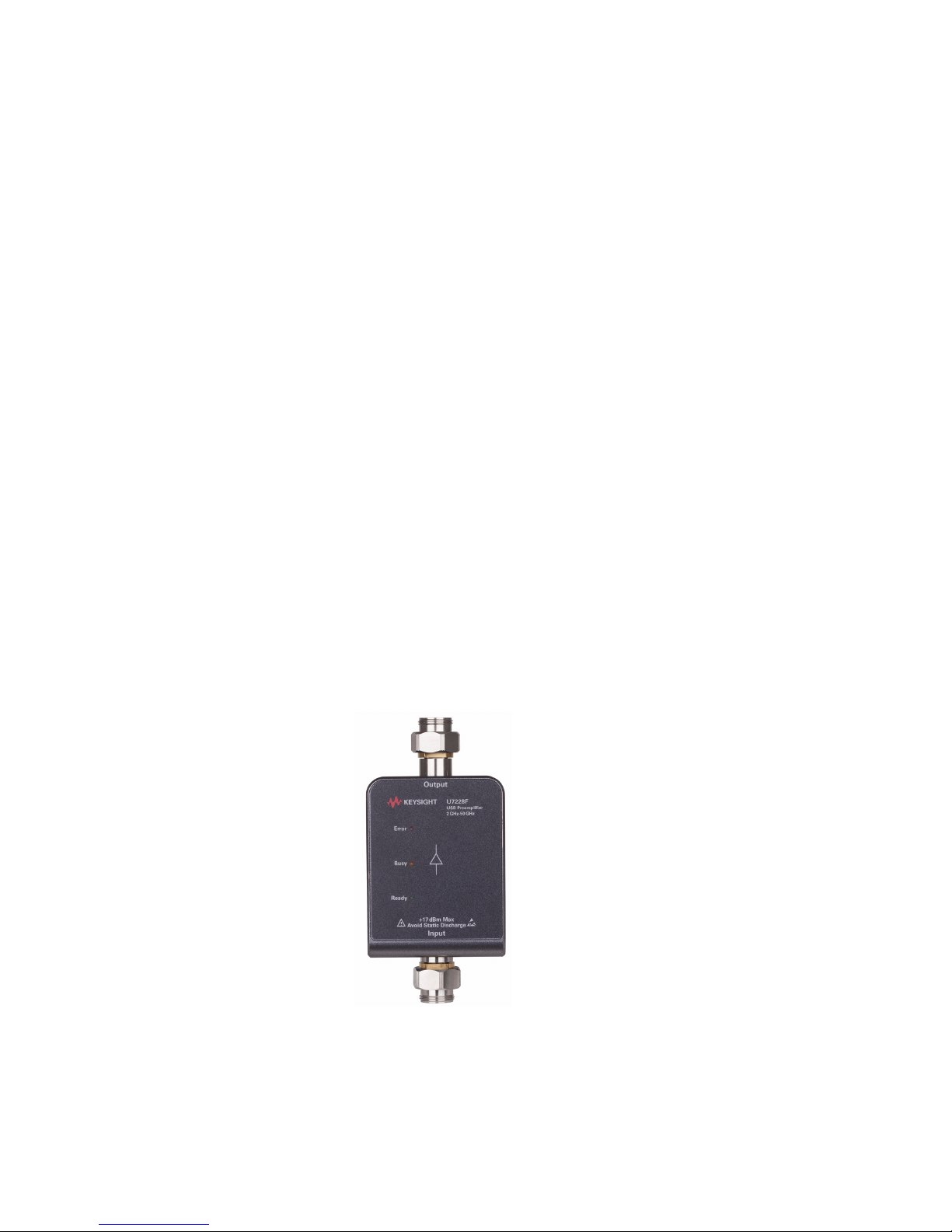
This chapter provides an overview of the Keysight U7228A/C/F USB Pre-Amplifier.
11
Page 12
1Introduction
Product Overview
In many RF systems, noise figure is known as a key parameter for characterizing a
receiver and its ability to detect weak incoming signals combined with
self-generated noise. The presence of these signals is typically low level, so
adding a reliable pre-amplifier will greatly increase the sensitivity of your
measurement system.
The Keysight U7228A/C/F USB pre-amplifier is designed to increase signal
analyzer’s sensitivity for measuring low-level signals by reducing instrument noise
figure. Reduced instrument noise figure also reduces noise figure measurement
uncertainty in most cases. Powered on a USB platform, compact and portable, the
USB pre-amplifier eliminates the need for an external power supply and is ideal
for either benchtop measurements or on remote front-end applications.
When connected to the Keysight X-Series signal analyzer, the USB pre-amplifier
can automatically configure the signal analyzer to detect the specific
pre-amplifier connected. The pre-amplifier will then download the embedded
calibration data such as gain, noise figure, and S-parameters. The calibration data
provides accurate correction data and more repeatable results for each
measurement made. The combined solution of the Keysight U7228A/C/F USB
pre-amplifier and the X-Series signal analyzer delivers the most efficient test
setup, highest accuracy, and lowest measurement uncertainty for noise figure
measurement applications up to 50 GHz.
Figure 1-1 U7228A/C/F USB Pre-Amplifier
12 Keysight U7228A/C/F Operating and Service Manual
Page 13

Key features of the U7228A/C/F USB Pre-Amplifier
– Automatic gain correction value with temperature compensation and transfer
of calibration data (noise figure and S-parameters) through USB
plug-and-play features for improved noise figure measurements with Keysight
N9040B UXA and N9010/20/30A X-Series signal analyzers
– Excellent noise figure and optimized gain with X-Series signal analyzers
improve measurement accuracy and minimize uncertainty
– Provides ultra-broadband operating frequency from 10 MHz up to 50 GHz for
various applications
– Rugged and portable design for benchtop measurements or remote front-end
applications
Introduction 1
Keysight U7228A/C/F Operating and Service Manual 13
Page 14

1Introduction
THIS PAGE HAS BEEN INTENTIONALLY LEFT BLANK.
14 Keysight U7228A/C/F Operating and Service Manual
Page 15

Keysight U7228A/C/F USB Pre-Amplifier
Operating and Service Manual
2 Installation
Initial Inspection 16
Verify the U7228A/C/F Shipment Contents 17
Service and Recalibration 17
Operating and Safety Precautions 18
USB Pre-Amplifiers Covered by this Guide 20
This chapter provides you important information on how to check and prepare
your instrument for operation.
15
Page 16

2Installation
Initial Inspection
1 Unpack and inspect the shipping container and its contents thoroughly to
ensure that nothing was damaged during shipment. If the shipping container
or cushioning material is damaged, the contents should be checked both
mechanically and electrically.
– Check for mechanical damage such as scratches or dents.
– Procedures for checking electrical performance are given under “Operator’s
2 If the contents are damaged or defective, contact your nearest Keysight
Technologies Service and Support Office. Refer to “Sales and Technical
Support” on page 4 of this manual. Keysight Technologies will arrange for
repair or replacement of the damaged or defective equipment. Keep the
shipping materials for the carrier's inspection.
3 If you are returning the instrument under warranty or for service, repackaging
the instrument requires original shipping containers and material or their
equivalents. Keysight Technologies can provide packaging materials identical
to the original materials. Refer to “Sales and Technical Support” on page 4 of
this manual for the Keysight Technologies nearest to you. Attach a tag
indicating the type of service required, return address, model number, and
serial number. Mark the container FRAGILE to insure careful handling. In any
correspondence, refer to the instrument by model number and serial number.
check” on page 36.
16 Keysight U7228A/C/F Operating and Service Manual
Page 17

Verify the U7228A/C/F Shipment Contents
The following table lists the items that are shipped with the U7228A/C/F.
Table 2-1 U7228A/C contents
Quantity Description Part number
1 Adapter-coaxial straight male-APC-N female-APC-3.5 1250-1744
1 Certificate of Calibration 5962-0476
Table 2-2 U7228F contents
Quantity Description Part number
1 Adapter 2.4 mm female - 2.4 mm female 85056-60006
1 Certificate of Calibration 5962-0476
Installation 2
Service and Recalibration
If your U7228A/C/F USB Pre-Amplifier requires service or repair, contact the
nearest Keysight office for information on where to send it. Refer to “Sales and
Technical Support” on page 4 of this manual. The performance of the
U7228A/C/F can only be verified by specially-manufactured equipment and
calibration standard from Keysight. The recommended interval for recalibration is
12 months.
Keysight U7228A/C/F Operating and Service Manual 17
Page 18

2Installation
Operating and Safety Precautions
Observe the following guidelines before connecting or operating the U7228A/C/F
USB Pre-Amplifier.
ESD damage
Protection against electrostatic discharge (ESD) is important while handling and
operating the U7228A/C/F USB Pre-Amplifier.
Static electricity can build up on your body and can easily damage sensitive
components when discharged.
Static discharges too small to be felt can cause permanent damage to the unit.
To prevent damage from ESD:
– Use a grounded antistatic mat in front of your test equipment and wear a
grounded wrist strap attached to it when handling or operating the
U7228A/C/F.
– Wear a heel strap when working in an area with a conductive floor.
– Ground yourself before you clean, inspect, or make a connection to the
U7228A/C/F. You can, for example, grasp the grounded outer shell of the
analyzer test port or cable connector briefly.
– Avoid touching the exposed connector pins.
18 Keysight U7228A/C/F Operating and Service Manual
Page 19

Connector care
CAUTION
Because connectors can become defective due to wear during normal use, all
connectors should be inspected and maintained to maximize their service life.
– Inspect the mating surface each time a connection is made. Metal particles
from connectors' threads often find their way onto the mating surface when a
connection is made or disconnected.
– Clean dirt and contamination from the connector mating surface and threads.
This simple step can extend the service life of the connector and improve the
quality of your calibration and measurements.
– Gage connectors periodically. This not only provides assurance of proper
mechanical tolerances, and thus connector performance, but can also indicate
situations where the potential for damage to another connector may exist.
The U7228A/C/F can be damaged if excessive torque is applied to the
connectors.
Installation 2
The recommended torque value is 8 lb-in for 2.4 mm and 3.5 mm type
connectors.
For the input and output ports, the recommended torque wrench is 20 mm
with part number 8710-1764.
Keysight U7228A/C/F Operating and Service Manual 19
Page 20

2Installation
Output
Input
USB connector
USB Pre-Amplifiers Covered by this Guide
There are three models available as follows:
– U7228A: USB Pre-Amplifier, 10 MHz to 4 GHz, Cable-less
– U7228C: USB Pre-Amplifier, 100 MHz to 26.5 GHz, Cable-less
– U7228F: USB Pre-Amplifier, 2 GHz to 50 GHz, Cable-less
20 Keysight U7228A/C/F Operating and Service Manual
Figure 2-1 U7228A/C/F
Indication light description
Ready
Busy
Error
When the USB Pre-Amplifier is connected with the X-Series signal
analyzer.
When communication between the USB Pre-Amplifier and the
X-Series signal analyzer is in progress.
– When there is a connection error or a data download error. The
X-Series signal analyzer is unable to communicate with the USB
Pre-Amplifier.
– When there is an input power overload at the X-Series signal
analyzer.
Page 21

Keysight U7228A/C/F USB Pre-Amplifier
Operating and Service Manual
3 Specifications
General Specifications 22
Mechanical Dimensions 31
Environmental Specifications 33
This chapter provides the specifications of the U7228A/C/F USB Pre-Amplifier.
21
Page 22

3 Specifications
General Specifications
Specifications
Specifications refer to the performance standards or limits against which the
U7228A/C/F is tested.
Typical characteristics are included for additional information only and they are
not specifications. These are denoted as "typical", "nominal", or "approximate",
and are printed in italic.
Table 3-1 U7228A/C/F specifications
Specification U7228A U7228C U7228F
Frequency 10 MHz to 4 GHz 100 MHz to 26.5 GHz 2 to 50 GHz
Gain (dB)
Input return loss
(Input SWR)
Output return loss
(Output SWR)
[b]
>16 (10 to 100 MHz)
>0.5F + 17 (100 MHz to 4 GHz)
>5 dB (3.57)
(10 to 100 MHz)
>13.5 dB (1.54)
(100 MHz to 2 GHz)
>11.5 dB (1.73)
(2 to 3 GHz)
>10 dB (1.93)
(3 to 4 GHz)
>18 dB (1.29)
(10 MHz to 4 GHz)
[a]
>0.26F + 16.1
(100 MHz to 26.5 GHz)
>15 dB (1.43)
(100 MHz to 4 GHz)
>8 dB (2.32)
(4 to 26.5 GHz)
>18 dB (1.29)
(100 MHz to 4 GHz)
>11 dB (1.78)
(4 to 26.5 GHz)
>0.23F + 16.5
(2 to 50 GHz)
>8 dB (2.32)
(2 to 40 GHz)
>6 dB (3.00)
(40 to 44 GHz)
>5 dB (3.57)
(44 to 50 GHz)
>18 dB (1.29)
(2 to 4 GHz)
>11 dB (1.78)
(4 to 26.5 GHz)
>8 dB (2.32)
(26.5 to 40 GHz)
>6 dB (3.00)
(40 to 50 GHz)
22 Keysight U7228A/C/F Operating and Service Manual
Page 23

Specifications 3
Tab le 3-1 U7228A/C/F specifications
[a]
(continued)
Specification U7228A U7228C U7228F
<6 dB (100 MHz to 4 GHz) <10 dB (2 to 4 GHz)
<5.5 dB (10 to 100 MHz) <5 dB (4 to 6 GHz) <8 dB (4 to 40 GHz)
Noise figure
<5 dB (10 MHz to 4 GHz) <4 dB (6 to 18 GHz) <9 dB (40 to 44 GHz)
<5 dB (18 to 26.5 GHz) <10 dB (44 to 50 GHz)
Bias voltage and
current (nominal)
USB 5 Vdc at 360 mA
USB 5 Vdc at 400 mA USB 5 Vdc at 460 mA
Survival input power +17 dBm +17 dBm +10 dBm
Power dissipation
(typical)
1.8 W 2 W 2.3 W
RF connector 3.5 mm (male) 3.5 mm (male) 2.4 mm (male)
Pin depth
Temperature
co-efficient (typical)
Plug-and-play USB
connection
0 to –0.05 mm
(0 to –0.002 in)
–0.009 dB/C –0.03 dB/C –0.18 dB/C
Yes Yes Yes
0 to –0.05 mm
(0 to –0.002 in)
0 to –0.05 mm
(0 to –0.002 in)
Optimized gain slope
for better spectrum
Yes Yes Yes
analysis
Automatic gain
compensation
Yes Yes Yes
Automatic
temperature
Yes Yes Yes
compensation
[a] Specifications are tested and measured on an operating temperature of 23 °C.
[b] "F" signifies frequency in GHz.
Keysight U7228A/C/F Operating and Service Manual 23
Page 24

3 Specifications
0
5
10
15
20
25
30
35
40
0.01
0.50875
1.0075
1.50625
2.005
2.50375
3.0025
3.50125
4
dB
Frequency (GHz)
Gain
Specification
0
1
2
3
4
5
6
7
8
9
10
0.01
0.51
1.01
1.51
2.01
2.50
3.00
3.50
4.00
dB
Frequency (GHz)
Noise Figure
Specification
-40
-35
-30
-25
-20
-15
-10
-5
0
0.01
0.51
1.01
1.51
2.01
2.50
3.00
3.50
4.00
dB
Frequency (GHz)
Input Return Loss
Specification
-40
-35
-30
-25
-20
-15
-10
-5
0
0.01
0.51
1.01
1.51
2.01
2.50
3.00
3.50
4.00
dB
Frequency (GHz)
Output Return Loss
Specification
Graphical performance data
Table 3-2 U7228A Pre-Amplifier Graphical Performance Data
Figure 3-1 Keysight U7228A Gain vs
Frequency (Typical)
Figure 3-3 Keysight U7228A Input Return
Loss vs Frequency (Typical)
Figure 3-2 Keysight U7228A Noise Figure vs
Frequency (Typical)
Figure 3-4 Keysight U7228A Output Return
Loss vs Frequency (Typical)
24 Keysight U7228A/C/F Operating and Service Manual
Page 25

Table 3-2 U7228A Pre-Amplifier Graphical Performance Data (continued)
-10
-5
0
5
10
15
0.01
0.51
1.01
1.51
2.01
2.50
3.00
3.50
4.00
dBm
Frequency (GHz)
Output P1dB
-100
-90
-80
-70
-60
-50
-40
-30
-20
-10
0
0.01
0.51
1.01
1.51
2.01
2.50
3.00
3.50
4.00
dB
Frequency (GHz)
Reverse Isolation
-10
0
10
20
30
40
50
60
0.01
0.51
1.01
1.51
2.01
2.50
3.00
3.50
4.00
dBm
Frequency (GHz)
Third Order Intercept (TOI)
Specifications 3
Figure 3-5 Keysight U7228A Output P1dB vs
Frequency (Typical)
Figure 3-7 Keysight U7228A Third Order
Intercept (TOI) vs Frequency
(Typical)
Figure 3-6 Keysight U7228A Reverse
Isolation vs Frequency (Typical)
Keysight U7228A/C/F Operating and Service Manual 25
Page 26

3 Specifications
0
5
10
15
20
25
30
35
40
0.1
3.4
6.7
10
13.3
16.6
19.9
23.2
26.5
dB
Frequency (GHz)
Gain
Specification
0
1
2
3
4
5
6
7
8
9
10
0.1
3.4
6.7
10.0
13.3
16.6
19.9
23.2
26.5
dB
Frequency (GHz)
Noise Figure
Specification
-40
-35
-30
-25
-20
-15
-10
-5
0
0.1
3.4
6.7
10.0
13.3
16.6
19.9
23.2
26.5
dB
Frequency (GHz)
Input Return Loss
Specification
-40
-35
-30
-25
-20
-15
-10
-5
0
0.1
3.4
6.7
10.0
13.3
16.6
19.9
23.2
26.5
dB
Frequency (GHz)
Output Return Loss
Specification
Table 3-3 U7228C Pre-Amplifier Graphical Performance Data
Figure 3-8 Keysight U7228C Gain vs
Frequency (Typical)
Figure 3-10 Keysight U7228C Input Return
Loss vs Frequency (Typical)
Figure 3-9 Keysight U7228C Noise Figure vs
Frequency (Typical)
Figure 3-11 Keysight U7228C Output Return
Loss vs Frequency (Typical)
26 Keysight U7228A/C/F Operating and Service Manual
Page 27

Table 3-3 U7228C Pre-Amplifier Graphical Performance Data (continued)
-10
-5
0
5
10
15
0.1
3.4
6.7
10.0
13.3
16.6
19.9
23.2
26.5
dBm
Freq uency (GHz)
Output P1dB
-100
-90
-80
-70
-60
-50
-40
-30
-20
-10
0
0.1
3.4
6.7
10.0
13.3
16.6
19.9
23.2
26.5
dB
Frequency (GHz)
Reverse Isolation
-10
0
10
20
30
40
50
60
0.1
3.4
6.7
10.0
13.3
16.6
19.9
23.2
26.5
dBm
Frequency (GHz)
Third Order Intercept (TOI)
Specifications 3
Figure 3-12 Keysight U7228C Output P1dB vs
Frequency (Typical)
Figure 3-14 Keysight U7228C Third Order
Intercept (TOI) vs Frequency
(Typical)
Figure 3-13 Keysight U7228C Reverse
Isolation vs Frequency (Typical)
Keysight U7228A/C/F Operating and Service Manual 27
Page 28

3 Specifications
0
5
10
15
20
25
30
35
40
2 8 14
20
26
32
38
44
50
dB
Frequency (GHz)
Gain
Specification
0
1
2
3
4
5
6
7
8
9
10
2 8 14
20
26
32
38
44
50
dB
Frequency (GHz)
Noise Figure
Specification
-40
-35
-30
-25
-20
-15
-10
-5
0
2 8 14
20
26
32
38
44
50
dB
Freq ency (GHz)
Input Return Loss
Specification
Table 3-4 U7228F Pre-Amplifier Graphical Performance Data
Figure 3-15 Keysight U7228F Gain vs
Frequency (Typical)
Figure 3-17 Keysight U7228F Input Return
Loss vs Frequency (Typical)
Figure 3-16 Keysight U7228F Noise Figure vs
Frequency (Typical)
Figure 3-18 Keysight U7228F Output Return
Loss vs Frequency (Typical)
28 Keysight U7228A/C/F Operating and Service Manual
Page 29
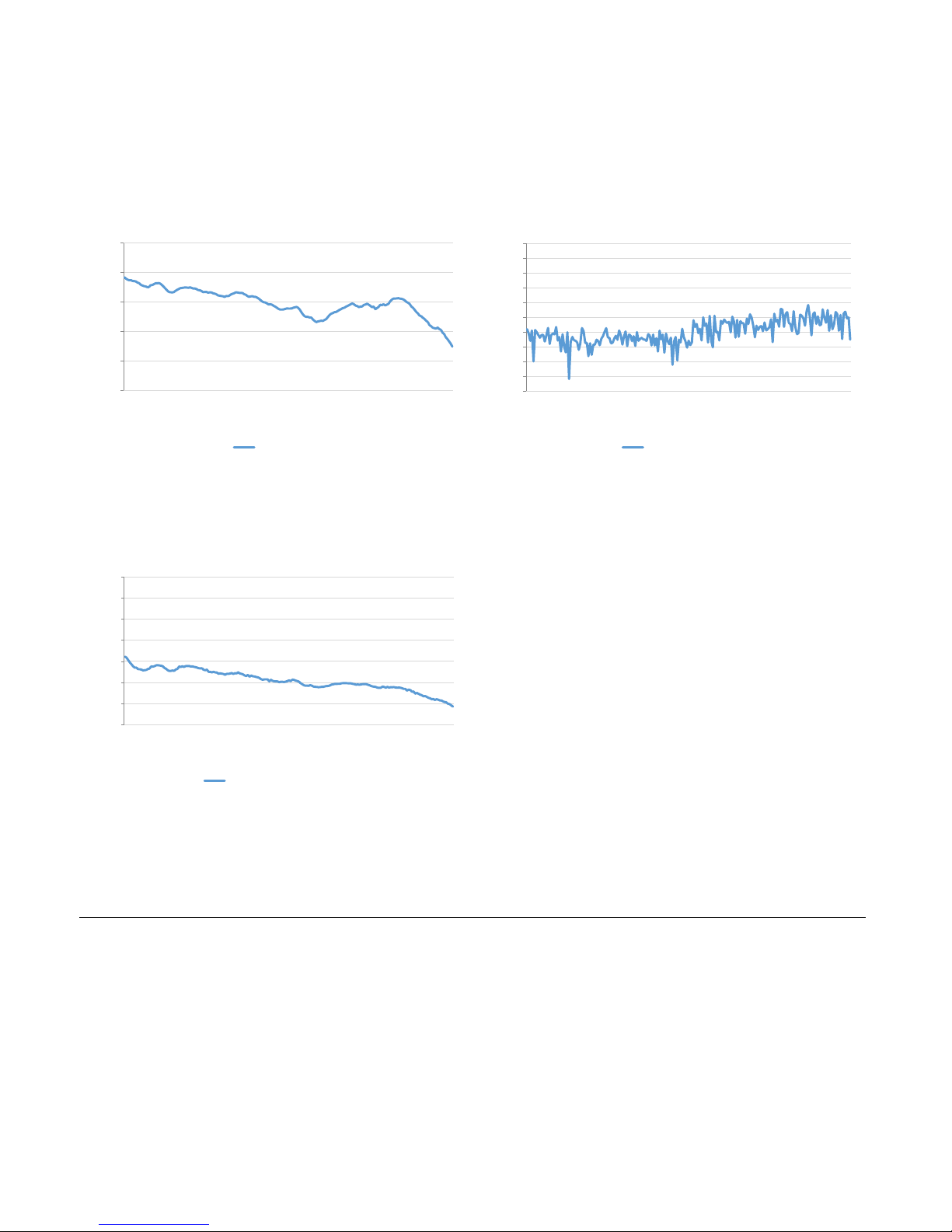
Table 3-4 U7228F Pre-Amplifier Graphical Performance Data (continued)
-10
-5
0
5
10
15
2 8 14
20
26
32
38
44
50
dBm
Frequency (GHz)
Output P1dB
-100
-90
-80
-70
-60
-50
-40
-30
-20
-10
0
2 8 14
20
26
32
38
44
50
dB
Frequency (GHz)
Reverse Isolation
-10
0
10
20
30
40
50
60
2 8 14
20
26
32
38
44
50
dBm
Frequency (GHz)
Third Order Intercept (TOI)
Specifications 3
Figure 3-19 Keysight U7228F Output P1dB vs
Frequency (Typical)
Figure 3-21 Keysight U7228F Third Order
Intercept (TOI) vs Frequency
(Typical)
Figure 3-20 Keysight U7228F Reverse
Isolation vs Frequency (Typical)
Keysight U7228A/C/F Operating and Service Manual 29
Page 30

3 Specifications
Physical specifications
Table 3-5 U7228A/C/F physical specifications
Net weight 0.36 kg (0.79 lbs)
Shipping weight 1.34 kg
Shipping dimensions:
– Length 430 mm (16.92 in)
– Width 260 mm (10.23 in)
– Height 170 mm (6.69 in)
30 Keysight U7228A/C/F Operating and Service Manual
Page 31
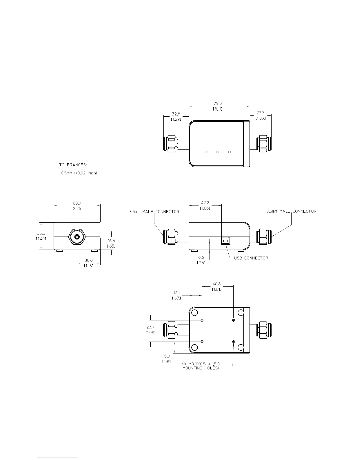
Mechanical Dimensions
Specifications 3
Figure 3-22 Mechanical dimensions of the U7228A/C
Keysight U7228A/C/F Operating and Service Manual 31
Page 32

3 Specifications
Figure 3-23 Mechanical dimensions of the U7228F
32 Keysight U7228A/C/F Operating and Service Manual
Page 33

Environmental Specifications
The U7228A/C/F is designed to fully comply with Keysight Technologies's product
operating environment specifications. The following table shows the summarized
environmental specifications for this product.
Table 3-6 U7228A/C/F environmental specifications
Temperature
–Operating
–Storage
Vibration
– Operating random
–Survival random
– Survival swept sine
Shock
– End-use handling
– Transportation
Specifications 3
0 to +55 °C
–40 °C to +70 °C
5 to 500 Hz, 0.21 grms
5 to 500 Hz, 2.09 grms
5 to 500 Hz, 0.5 grms
1.6 m/s
50 g, 8 m/s
Humidity
–Operating
–Storage
ESD immunity
– Direct discharge
– Air discharge
50% to 95% Relative Humidity (RH) at 40 °C
90% RH at 65 °C
6 kV per IEC 61000-4-2
15 kV per IEC 61000-4-2
Keysight U7228A/C/F Operating and Service Manual 33
Page 34

3 Specifications
THIS PAGE HAS BEEN INTENTIONALLY LEFT BLANK.
34 Keysight U7228A/C/F Operating and Service Manual
Page 35

Keysight U7228A/C/F USB Pre-Amplifier
Operating and Service Manual
4 Operating Guides
Operating Instructions 36
Service and Maintenance 39
This chapter provides simple quick-check instructions to verify the U7228A/C/F
USB Pre-Amplifier functionality prior to usage.
35
Page 36

4 Operating Guides
CAUTION
Input
Output
USB connection
U7228A/C/F USB Pre-Amplifier
Operating Instructions
Operator’s check
The operator's check is supplied to allow the operator to make quick check of the
U7228A/C/F prior to use or if a failure is suspected.
ESD exceeding the level specified in Table 3-6 or RF power applied is greater
than the maximum specified as in Table 3-1 may cause permanent damage
to the device.
Operator's check for the S-parameter test
Any network Analyzer with a USB supply can be used for performance test
verification. The equipment setup is as illustrated below.
36 Keysight U7228A/C/F Operating and Service Manual
Figure 4-1 Quick-check configuration for the S-parameter test
Page 37

Operating Guides 4
Quick-check procedure
1 Set the following parameters on the network analyzer to perform 2-port
measurements:
Table 4-1 S-parameter measurement parameters
U7228A U7228C U7228F
Start Frequency 10 MHz 100 MHz 2 GHz
Stop Frequency 4 GHz 26.5 GHz 50 GHz
Points 201 201 201
IFBW 100 Hz 100 Hz 100 Hz
Input Power –30 dBm –40 dBm –50 dBm
Note: The same frequency settings (start frequency and stop frequency) and number of points apply for
all parameters.
2 Calibrate the network analyzer using the appropriate calibration procedure.
3 Connect the input of the pre-amplifier to port 1 of the network analyzer and
the output to port 2.
4 Connect the pre-amplifier to the USB supply of the network analyzer.
5 Obtain the measurement result for S11 (input return loss), S22 (output return
loss), and S21 (gain).
6 Compare the measurement results with the specifications in Table 3-1.
Keysight U7228A/C/F Operating and Service Manual 37
Page 38

4 Operating Guides
Operator’s check for the noise figure measurement
1 Set the following parameters on the network analyzer to perform 2-port
measurements:
Table 4-2 Noise figure measurement parameters
Start Frequency 10 MHz 100 MHz 2 GHz
Stop Frequency 4 GHz 26.5 GHz 50 GHz
Points 201 201 201
Input Power –30 dBm –40 dBm –50 dBm
Bandwidth 2 MHz 2 MHz 2 MHz
Gain Medium Medium Low
2 Calibrate the network analyzer for noise figure measurements.
U7228A U7228C U7228F
3 Connect the input of the pre-amplifier to port 1 of the network analyzer and
the output to port 2.
4 Connect the pre-amplifier to the USB supply of the network analyzer.
5 Obtain the measurement result for noise figure.
6 Compare the measurement results with the specifications in Table 3 -1.
38 Keysight U7228A/C/F Operating and Service Manual
Page 39

Service and Maintenance
Service
The U7228A/C/F does not have internal adjustments and should not be opened; it
should only be repaired by service-trained personnel. Should it become necessary
to return the U7228A/C/F for repair or service, contact your nearest Keysight
Sales and Service Center.
Maintenance
The connectors of the U7228A/C/F, particularly the connector faces must be kept
clean. Keysight recommends that the connectors be periodically inspected and
cleaned if necessary. For instructions on the connection and maintenance of your
connectors, refer to the Connector Care Quick Reference Card (08510-90360).
Operating Guides 4
Keysight U7228A/C/F Operating and Service Manual 39
Page 40

4 Operating Guides
THIS PAGE HAS BEEN INTENTIONALLY LEFT BLANK.
40 Keysight U7228A/C/F Operating and Service Manual
Page 41

This information is subject to change
without notice. Always refer to the
English version at the Keysight
website for the latest revision.
© Keysight Technologies 2015
Edition 1, Feb 1, 2016
Printed in Malaysia
*U7228-90001*
U7228-90001
www.keysight.com
 Loading...