

Page 1
Keysight Protocol
Exerciser for PCI Express
Hardware Guide
Page 2

Notices
CAUTION
WARNING
© Keysight Technologies 2011-2015
No part of this manual may be reproduced in
any form or by any means (includ ing electronic storage and retrieval or translation
into a foreign language) without prior agreement and written consent from Keysight
Technologies as governed by United States
and international copyright laws.
Installation Guide
You can find the installation guides for different components of the product on the
product CD. Keysight recommends you to
do not switch on the instrument before you
have understood all the applicable installation instructions and have met all the installation prerequisites.
Where to find more information
You can find more information about
System Protocol Tester from the following
link:
http://www.keysight.com/find/spt
You can also look for search a local contact
for assistance on the following link:
http://www.keysight.com/find/assist
Warranty
THE MATERIAL CONTAINED IN THIS
DOCUMENT IS PROVIDED "AS IS," AND IS
SUBJECT TO BEING CHANGED, WITHOUT
NOTICE, IN FUTURE EDITIONS. FURTHER,
TO THE MAXIMUM EXTENT PERMITTED BY
APPLICABLE LAW, KEYSIGHT DISCLAIMS
ALL WARRANTIES, EITHER EXPRESS OR
IMPLIED WITH REGARD TO THIS MANUAL
AND ANY INFORMATION CONTAINED
HEREIN, INCLUDING BUT NOT LIMITED TO
THE IMPLIED WARRANTIES OF
MERCHANTABILITY AND FITNESS FOR A
PARTICULAR PURPOSE. KEYSIGHT SHALL
NOT BE LIABLE FOR ERRORS OR FOR
INCIDENTAL OR CONSEQUENTIAL
DAMAGES IN CONNECTION WITH THE
FURNISHING, USE, OR PERFORMANCE OF
THIS DOCUMENT OR ANY INFORMATION
CONTAINED HEREIN. SHOULD KEYSIGHT
AND THE USER HAVE A SEPARATE WRITTEN
AGREEMENT WITH WARRANTY TERMS
COVERING THE MATERIAL IN THIS
DOCUMENT THAT CONFLICT WITH THESE
TERMS, THE WARRANTY TERMS IN THE
SEPARATE AGREEMENT WILL CONTROL.
Technology Licenses
The hardware and/or software described in
this document are furnished under a license
and may be used or copied only in accordance with the terms of such license.
52.227-14 (June 1987) or DFAR
252.227-7015 (b)(2) (November 1995), as
applicable in any technical data.
Safety Notices
A CAUTION notice denotes a hazard. It
calls attention to an operating procedure, practice, or the like that, if not
correctly performed or adhered to,
could result in d amage to the prod uct
or loss of important data. Do not proceed beyond a CAUTION notice until
the indicated conditions are fully
understood and met.
A WARNING notice denotes a hazard.
It calls attention to an operating procedure, practice, or the like that, if not
correctly performed or adhered to,
could result in personal injury or
death. Do not proceed beyond a
WARNING notice until the indicated
conditions are fully understood and
met.
Restricted Rights Legend
If software is for use in the performance of a
U.S. Government prime contract or subcontract, Software is delivered and licensed as
"Commercial computer software" as defined
in DFAR 252.227-7014 (June 1995), or as a
"commercial item" as defined in FAR
2.101(a) or as "Restricted computer software" as defined in FAR 52.227-19 (June
1987) or any equivalent agency regulation or
contract clause. Use, duplication or disclosure of Software is subject to Keysight Technologies’ standard commercial license
terms, and non-DOD Departments and
Agencies of the U.S. Government will receive
no greater than Restricted Rights as defined
in FAR 52.227-19(c)(1-2) (June 1987). U.S.
Government users will receive no greater
than Limited Rights as defined in FAR
2 Keysight Protocol Exerciser for PCI Express Hardware Guide
Page 3

Safety Summary
CAUTION
WARNING
General Do not use this product in any manner not specified by the manufacturer. The protective features of
The following general safety precautions must be observed during all phases of operation of this
instrument. Failure to comply with these precautions or with specific warnings or operating
instructions in the product manuals violates safety standards of design, manufacture, and intended
use of the instrument. Keysight Technologies assumes no liability for the customer's failure to comply
with these requirements. Product manuals are provided with your instrument on CD-ROM and/or in
printed form. Printed manuals are an option for many products. Manuals may also be available on
the Web. Go to www.keysight.com and type in your product number in the Search field at the top of
the page.
this product may be impaired if it is used in a manner not specified in the operation instructions.
Before Applying
Power
Ground the
Instrument
Fuses See the user's guide or operator's manual for information about line-fuse replacement. Some
Do Not Operate in
an Explosive
Atmosphere
Do Not Remove the
Instrument Cover
Cleaning Clean the outside of the instrument with a soft, lint-free, slightly dampened cloth. Do not use
Do Not Modify the
Instrument
Verify that all safety precautions are taken. Make all connections to the unit before applying power.
Note the instrument's external markings described in “Safety Symbols”.
If your product is provided with a grounding type power plug, the instrument chassis and cover must
be connected to an electrical ground to minimize shock hazard. The ground pin must be firmly
connected to an electrical ground (safety ground) terminal at the power outlet. Any interruption of
the protective (grounding) conductor or disconnection of the protective earth terminal will cause a
potential shock hazard that could result in personal injury.
instruments contain an internal fuse, which is not user accessible.
Do not operate the instrument in the presence of flammable gases or fumes.
Only qualified, service-trained personnel who are aware of the hazards involved should remove
instrument covers. Always disconnect the power cable and any external circuits before removing the
instrument cover.
detergent or chemical solvents.
Do not install substitute parts or perform any unauthorized modification to the product. Return the
product to an Keysight Sales and Service Office for service and repair to ensure that safety features
are maintained.
In Case of Damage Instruments that appear damaged or defective should be made inoperative and secured against
unintended operation until they can be repaired by qualified service personnel.
A CAUTION notice denotes a hazard. It calls attention to an operating procedure, practice,
or the like that, if not correctly performed or adhered to, could result in damage to the
product or loss of important data. Do not proceed beyond a CAUTION notice until the
indicated conditions are fully understood and met.
A WARNING notice denotes a hazard. It calls attention to an operating procedure,
practice, or the like that, if not correctly performed or adhered to, could result in
personal injury or death. Do not proceed beyond a WARNING notice until the indicated
conditions are fully understood and met.
Keysight Protocol Exerciser for PCI Express Hardware Guide 3
Page 4
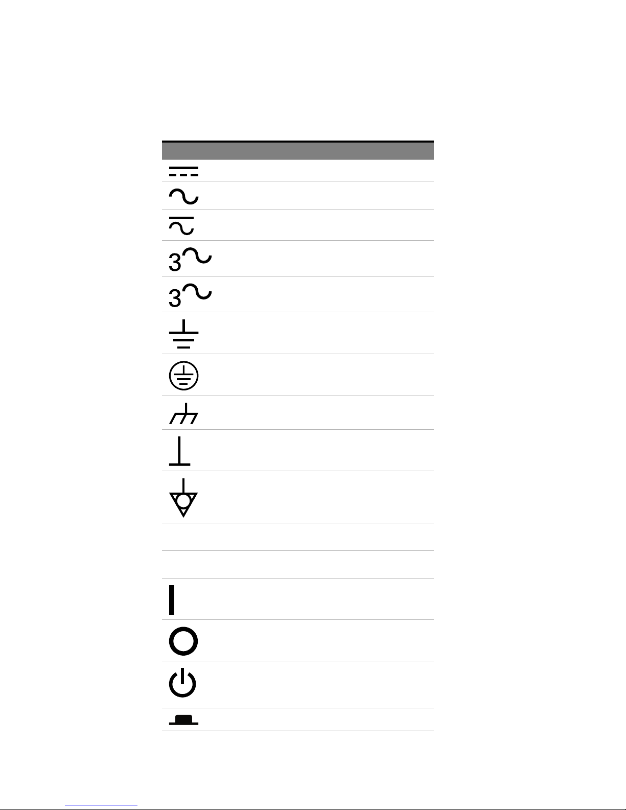
Safety Symbols
Table 1 Safety Symbol
Symbol Description
Direct current
Alternating current
Both direct and alternating current
Three phase alternating current
Three phase alternating current
Earth ground terminal
Protective earth ground terminal
Frame or chassis ground terminal
N Neutral conductor on permanently
L Line conductor on permanently installed
Terminal is at earth potential
Equipotentiality
installed equipment
equipment
On (mains supply)
Off (mains supply)
Standby (mains supply). The instrument is
not completely disconnected from the
mains supply when the power switch is in
the standby position
4 Keysight Protocol Exerciser for PCI Express Hardware Guide
In position of a bi-stable push switch
Page 5
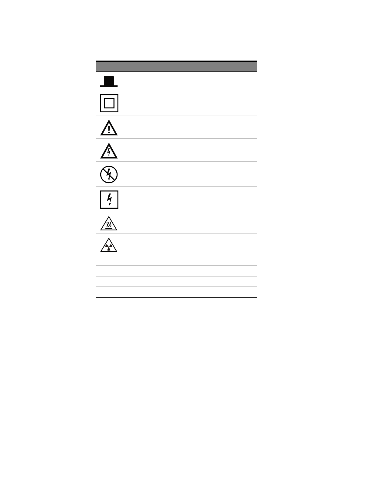
Symbol Description
Out position of a bi-stable push switch
Equipment protected throughout by
DOUBLE INSULATION or REINFORCED
INSULATION
Caution, refer to accompanying
documentation
Caution, risk of electric shock
Do not apply around or remove from
HAZARDOUS LIVE conductors
Application around and removal from
HAZARDOUS LIVE conductors is
permitted
Caution, hot surface
Ionizing radiation
CAT I IEC Measurement Category I
CAT II Measurement Category II
CAT III Measurement Category III
CAT IV Measurement Category IV
Keysight Protocol Exerciser for PCI Express Hardware Guide 5
Page 6
Compliance and Environmental Information
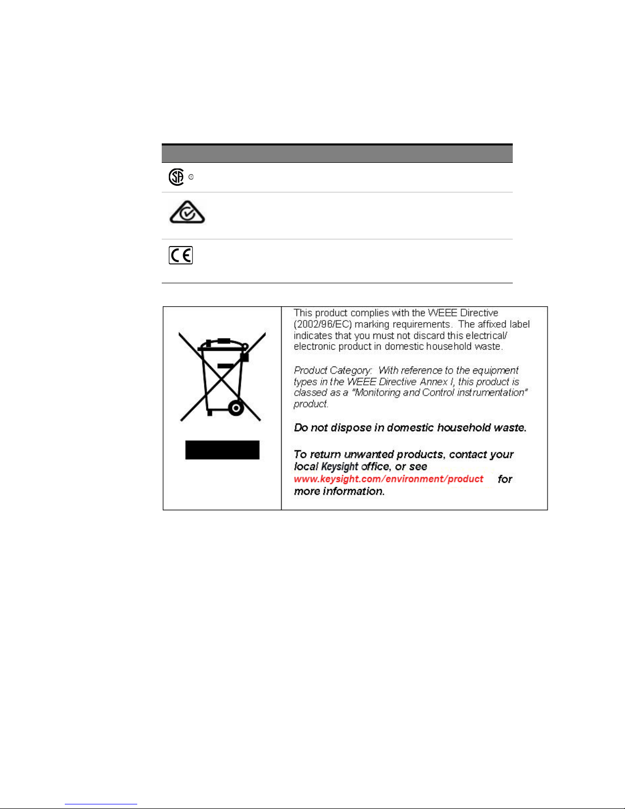
Table 2 Compliance and Environmental Information
Safety Symbol Description
CSA is the Canadian certification mark to demonstrate compliance with the Safety
requirements.
The C-tick mark is a registered trademark of the Spectrum Management
Agency of Australia. This signifies compliance with the Australia EMC
Framework regulations under the terms of the Radio Communication Act
of 1992.
CE compliance marking to the EU Safety and EMC Directives.
ISM GRP-1A classification accord ing to the international EMC stand ard.
ICES/NMB-001 compliance marking to the Canadian EMC standard.
6 Keysight Protocol Exerciser for PCI Express Hardware Guide
Page 7

Printing History
Keysight Technologies can issue revisions between the product releases to reflect the latest and
correct information in the guide. Keysight Technologies also reserves its right to not issue a new
edition of the guide for every system release.
Manual Name: Keysight Protocol Exerciser for PCI Express- Hardware Guide
The edition number of the guide, publishing time of the guide, and applicable release number of the
product are given in the following table.
Edition Published Applicable Release
1.4 February, 2015 8.76
Keysight Protocol Exerciser for PCI Express Hardware Guide 7
Page 8

8 Keysight Protocol Exerciser for PCI Express Hardware Guide
Page 9

Contents
1 U4305A/U4305B Exerciser Card
U4305A/U4305B Exerciser Card - Introduction 12
Features 13
Components 14
Exerciser Card Status LEDs 16
U4305A/U4305B Exerciser Card as an Endpoint 19
U4305A/U4305B Exerciser Card as a Root Complex 20
Index
Keysight Protocol Exerciser for PCI Express Hardware Guide 9
Page 10

Contents
10 Keysight Protocol Exerciser for PCI Express Hardware Guide
Page 11

Keysight Protocol Exerciser for PCI Express
Hardware Guide
1 U4305A/U4305B Exerciser
Card
U4305A/U4305B Exerciser Card - Introduction / 12
Features / 13
Components / 14
U4305A/U4305B Exerciser Card as an Endpoint / 19
U4305A/U4305B Exerciser Card as a Root Complex / 20
This chapter provides information on the U4305A/U4305B exerciser card used for testing PCIe
devices. This chapter describes the card’s emulation modes, hardware features, components, and
sample hardware configuration scenarios for this card in the overall setup.
Page 12

1 U4305A Exerciser Card
NOTE
U4305A/U4305B Exerciser Card - Introduction
The Keysight U4305A/U4305B exerciser card is a test and debug tool that provides features for
testing the next generation of PCI Express technology. You can use this card to stimulate PCIe
components on system boards and cards with various test scenarios. The Exerciser card can emulate
a PCIe device or a topology with or without SRIOV / MRIOV capabilities and can provide test
conditions to test components on system boards and cards.
The U4305A/U4305B Exerciser card provides the functions of an LTSSM as well as an Exerciser to
help you perform thorough PCIe link testing and validation testing for the DUT. As an LTSSM Tester,
the Exerciser card helps you verify the DUT’s LTSSM state transitions and timeout implementations.
As an Exerciser, it exercises DUT with the configured stimulus traffic. It can send TLP requests as well
as completions to a DUT.
The U4305A/U4305B Exerciser card can emulate a PCIe endpoint and act as a Downstream
Component (DSC) for a System Under Test. It can also emulate a root complex and act as an
Upstream Component to stimulate a PCIe Device Under Test. Refer to the topics “U4305A/U4305B
Exerciser Card as an Endpoint and “U4305A/U4305B Exerciser Card as a Root Complex to know
more.
For information on installing and configuring the U4305A/U4305B exerciser
card, refer to Keysight PCIE Exerciser Gen3, Installation Guide.
For information on how to use the U4305A/U4305B exerciser card, refer to
Keysight Protocol Exerciser for PCI Express, User Guide.
12 Keysight Protocol Exerciser for PCI Express Hardware Guide
Page 13

Features
NOTE
U4305A Exerciser Card 1
This topic describes the features of the U4305A/U4305B exerciser card.
• It is a standard height, half-length card as described in the PCI Express specification, and fits into
every system including blade servers.
• It supports LTSSM functions for upto x16 link widths.
• It supports simultaneous use of LTSSM and Protocol Exerciser functions, without requiring any
configuration.
• It supports Gen1 (2.5 GT/s), Gen2 (5.0 GT/s), and Gen3 (8.0 GT/s) speeds as per PCIe
specifications.
• It provides non IOV, SRIOV, and MRIOV capabilities based on the licensed options.
• It supports NVMe root complex and endpoint emulation capabilities based on the licensed
options.
• You can manage, control, and use it using the Protocol Exerciser GUI and APIs.
The U4305B model of Exerciser supports L1.1 and L1.2 L1 substates in both the ASPM and
PCI-PM L1 Link states. This feature is not supported by the U4305A model.
The U4305B model uses a per-Link signal called Reference Clock Request CLKREQ# (Pin B12
of PCIe connector) for L1 substates management. Exerciser or the link partner can request a
clock power off using this signal. When the reference clock of both the link partners is
switched off, the link can go to an L1 substate.
Keysight Protocol Exerciser for PCI Express Hardware Guide 13
Page 14
1 U4305A Exerciser Card
Components
This topic describes the hardware components of the U4305A/U4305B exerciser card.
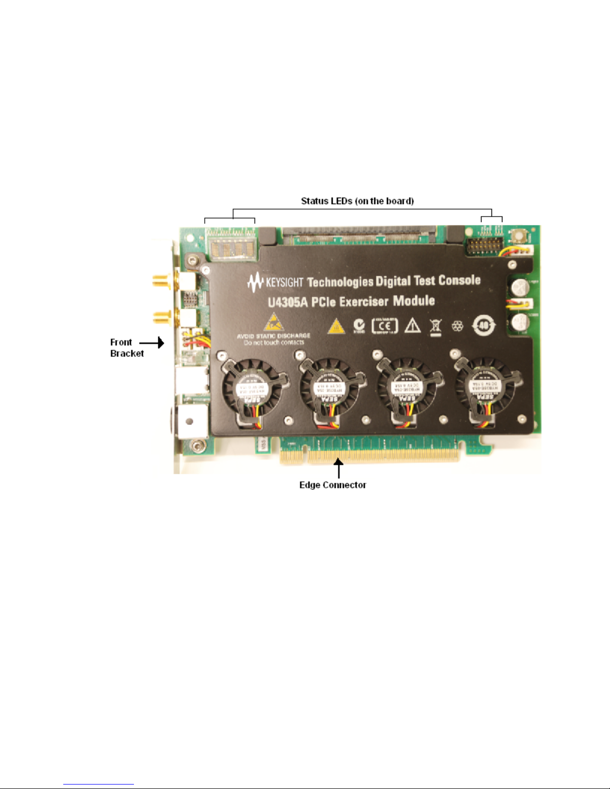
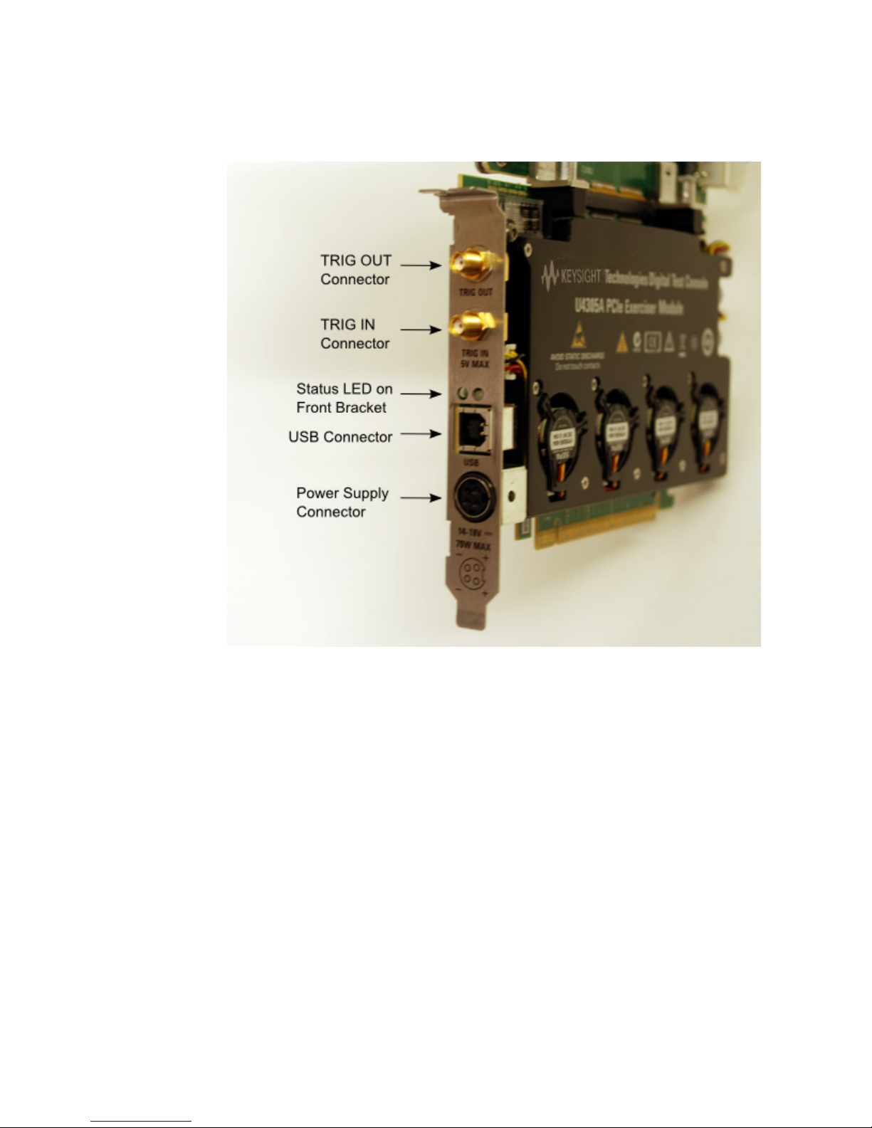
Figure 1 and Figure 2 display the U4305A/U4305B exerciser card to indicate the various components
of this card.
Figure 1 U4305A/U4305B Exerciser Card
14 Keysight Protocol Exerciser for PCI Express Hardware Guide
Page 15
U4305A Exerciser Card 1
r
Figure 2 U4305A/U4305B Exerciser Card components on front bracket
The hardware components displayed in the above figures of the U4305A/U4305B Exerciser card are
described:
• Edge Connector: This component is used to connect the U4305A/U4305B card with a PCIe
Connector on the backplane board, or with a system.
• Status LEDs (on board): This component has the LEDs to display the status information about the
participating lanes of the link and power status of board and exerciser card. 16 LEDs displaying
the lane status are in the upper left corner of the board and the rest of the 7 LEDs are in the upper
right corner of the board. The module number to which U4305A/U4305B is configured is also
displayed in the upper left corner.
To get a description of each LED on the board, refer to the topic “Exerciser Card Status LEDs in
this chapter.
• Status LEDs (on front bracket):
The green LED represents the link speed status and has the following different states:
• No light means there is no link up between the Exerciser card and DUT.
• Green light means there is a link up at the Gen3 speed (8.0 GT/s).
• Fast blinking light means there is a link up at the Gen2 speed (5.0 GT/s).
• Slow blinking light means there is a link up at the Gen1 speed (2.5 GT/s).
The red LED on the front bracket will be on until the FPGA receives a valid configuration.
Keysight Protocol Exerciser for PCI Express Hardware Guide 15
Page 16
1 U4305A Exerciser Card
WARNING
CAUTION
NOTE
• USB Connector: This component is used to connect U4305A/U4305B with the controller PC using
the USB cable.
• Power Supply Connector: This component is used to connect U4305A/U4305B with the external
power supply. Use the power supply delivered with U4305A only.
• TRIG OUT Connector: This component is used to connect the U4305A/U4305B card with other test
equipments such as Protocol Analyzer to trigger these test equipments. The Exerciser card
generates a trigger out pulse when a specified trigger out condition is met.
• TRIG IN Connector: This component is used to connect the U4305A/U4305B card with other test
equipments such as Protocol Analyzer to receive a trigger from these test equipments when a
specified condition is met.
The electrical characteristics of the Trigger In/Out are as follows:
• Trigger In: Vin Low Max = 0.9V, Vin High Min = 2.0V max, Input current +/- 5uA. The width of
the trigger in pulse should be greater than 32 ns.
• Trigger Out: TTL levels series terminated with 50 Ohms. Vout High Min (no load termination) =
2.4V, Vout Low Max (no load termination) = 0.4V; Vout High Min (with 50 Ohms External
termination to GND) = 1.2V, Vout Low Max (with 50 Ohms External termination to GND) = 0.2V.
The width of the trigger out pulse is 125 ns.
Do not directly touch any component on the U4305A/U4305B exerciser card. It
may be hot.
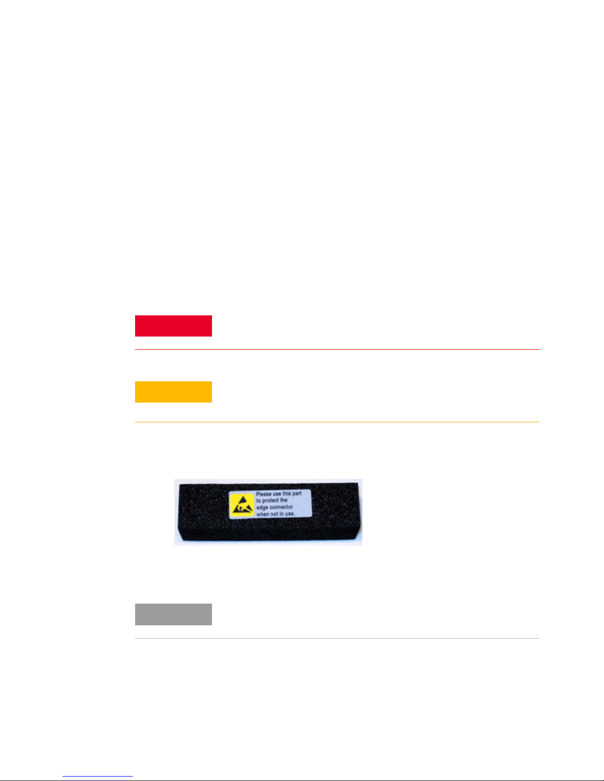
This component comes with a protective foam cover to protect it from electrostatic damage
(Figure 3).
Figure 3 Protective Foam Cover for Edge Connector
Exerciser Card Status LEDs
Components on the U4305A/U4305B exerciser card are sensitive to the static
electricity. Therefore, take necessary anti-static precautions, such as wear a
grounded wrist strap, to minimize the possibility of electrostatic damage.
Please remove the protective foam cover before using the card, and attach it
again when the card is not in use.
The U4305A/U4305B
bracket. This topic describes the meaning of each of these status LEDs.
The following figure displays the status LEDs on board.
16 Keysight Protocol Exerciser for PCI Express Hardware Guide
Exerciser card has a number of status LEDs on the board and on the front
Page 17
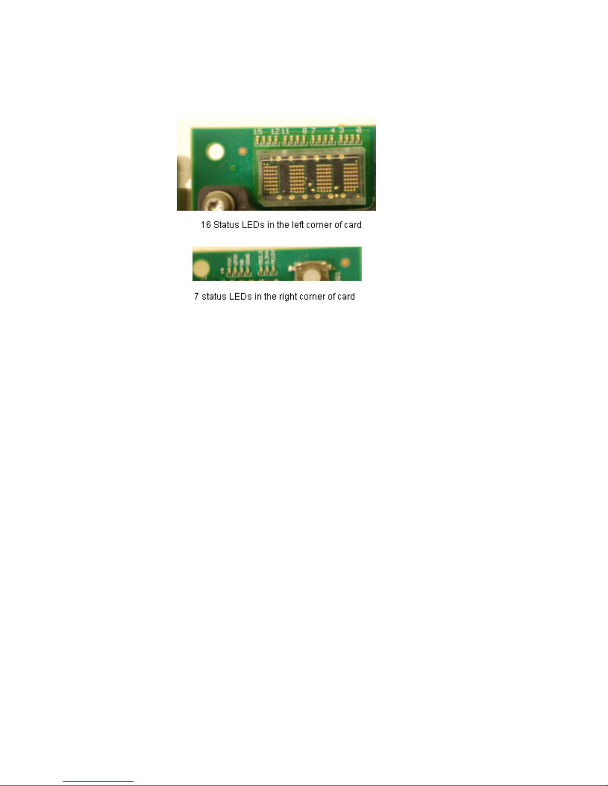
Figure 4 Exerciser card status LEDs
U4305A Exerciser Card 1
The following table describes the status LEDs on board and on the front bracket.
Keysight Protocol Exerciser for PCI Express Hardware Guide 17
Page 18

1 U4305A Exerciser Card
Table 3 Exerciser card status LEDs
LED Name/Label Description
Status LEDs on the board
16 status LEDs in upper left corner of the
board
POK When this LED is ON, it indicates that the FPGA power supplies are
UPOK When this LED is ON, it ind icates that the Power supplies for the
HB This LED represents the Heartbeat. It bl inks at about 1 second rate to
DONE When this LED is on, it indicates that FPGA has been programmed
PE3.3 When this LED is on, it ind icates that the +3.3V PCI Express power
3.3VA When this LED is on, it indicates that the +3.3V Aux PCI Express power
PE12V When this LED is on, it indicates that the +12V PCI Express power
Displays the status of the lanes (x1-x16) in the link.
All these LEDs are off if the link is not up.
If the link is up, then the LEDs are on for only those lanes that are
participating in the link.
operating.
This is displayed in the upper right corner of the board.
microprocessor system and USB are operating.
This is displayed in the upper right corner of the board.
indicate that the microprocessor is operating.
This is displayed in the upper right corner of the board.
successfully.
This is displayed in the upper right corner of the board.
supply from the bottom (SYS) connector is up.
This is displayed in the upper right corner of the board.
supply from the bottom (SYS) connector is up.
This is displayed in the upper right corner of the board.
supply from the bottom (SYS) connector is up.
This is displayed in the upper right corner of the board.
Status LEDs on front bracket
No light There is no link up between the Exerciser card and DUT.
Green There is a link up at the Gen3 speed (8.0 GT/s).
Fast Blinking light There is a link up at the Gen2 speed (5.0 GT/s).
Slow Blinking light There is a link up at the Gen1 speed (2.5 GT/s).
Red LED The red LED on the front bracket will be on until the FPGA receives a
18 Keysight Protocol Exerciser for PCI Express Hardware Guide
valid configuration.
Page 19
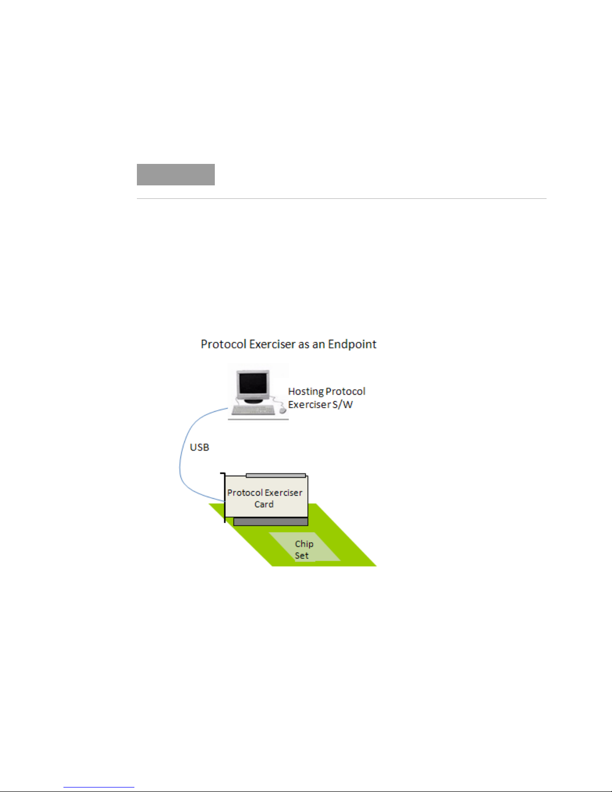
U4305A/U4305B Exerciser Card as an Endpoint
NOTE
This topic introduces you to the U4305A/U4305B exerciser card emulating a PCIe endpoint.
For detailed information on how to set up the U4305A/U4305B exerciser card as
a PCIe endpoint, refer to the Keysight PCIE Exerciser Gen3 Installation guide.
You can use the U4305A/U4305B exerciser card as an endpoint to stimulate a System Under Test
into various test scenarios. To accomplish this, you plug the exerciser card as a normal PCIe device
into the motherboard under test through the Edge connector of the card.
A controller system hosts the Protocol Exerciser software and hardware support services to control
and manage the Exerciser card. Exerciser card is connected to this controller system through a USB
cable. The following figure displays a sample hardware setup in which the U4305A/U4305B exerciser
card is emulating a PCIe endpoint.
U4305A Exerciser Card 1
Figure 5 Exerciser card emulating a PCIe endpoint
Keysight Protocol Exerciser for PCI Express Hardware Guide 19
Page 20
1 U4305A Exerciser Card
NOTE
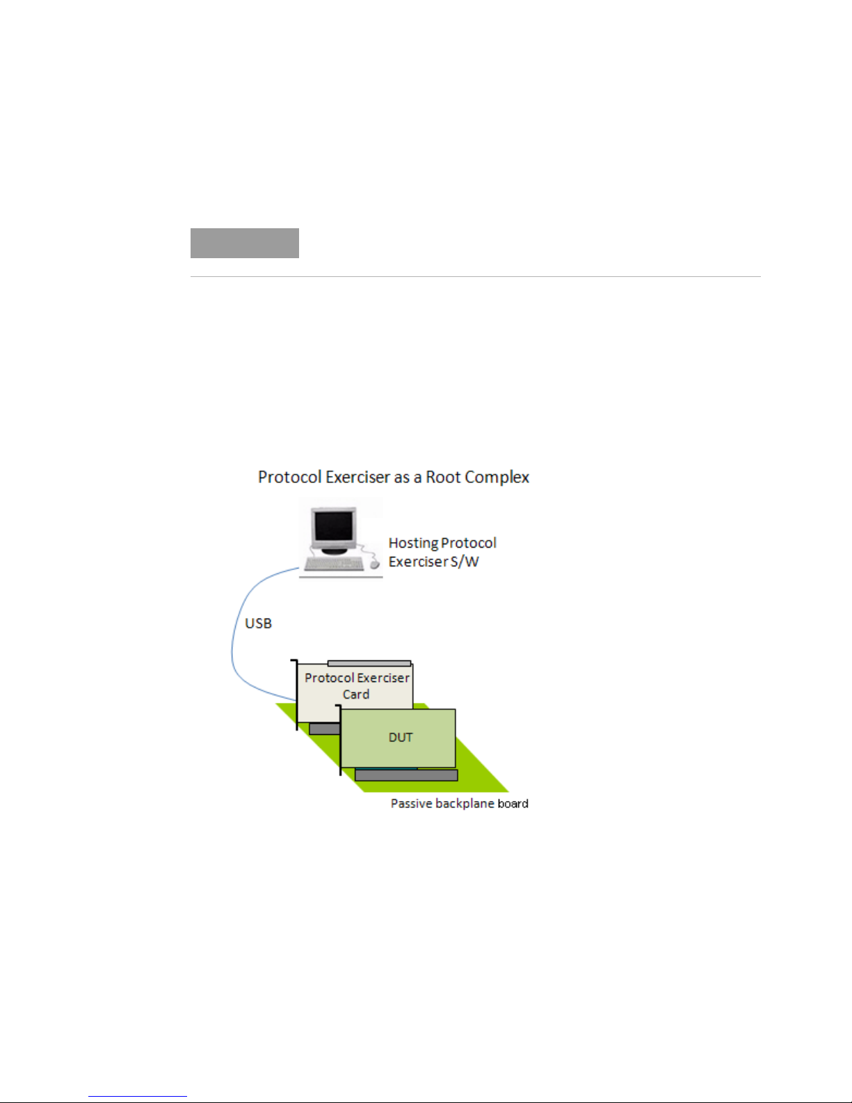
U4305A/U4305B Exerciser Card as a Root Complex
This topic introduces you to the U4305A/U4305B exerciser card emulating a root complex.
For detailed information on how to set up the U4305A/U4305B exerciser card as
a root complex, refer to the Keysight PCIE Exerciser Gen3 Installation guide.
You can use the U4305A/U4305B exerciser card as a root complex to stimulate a DUT into various
test scenarios. To accomplish this, you plug the exerciser card into a passive backplane board
through the Edge connector of the card. In this case, the Exerciser card communicates to the DUT
through the bottom connectors.
A controller system hosts the Protocol Exerciser software and hardware support services to control
and manage the Exerciser card. Exerciser card is connected to this controlling system through a USB
cable. The following figure displays a sample hardware setup in which the U4305A/U4305B exerciser
card is emulating a PCIe root complex.
Figure 6 Exerciser card emulating a root complex
20 Keysight Protocol Exerciser for PCI Express Hardware Guide
Page 21

Index
E
Edge Connector, 15
H
hardware components, 14
P
Power Supply Connector (front
bracket), 16
S
Status LED (on front bracket), 15
Status LEDs, 15
T
Trigger Connector, 16
U
U4305A/U4305B exerciser card, 12
USB Connector, 16
Keysight Protocol Exerciser for PCI Express Hardware Guide 21
Page 22

Index
22 Keysight Protocol Exerciser for PCI Express Hardware Guide
 Loading...