

Page 1

Keysight U1452A/U1452AT/
U1451A Insulation Tester
Quick Start Guide
Page 2

Page 3

U1452A/U1452AT/U1451A Insulation Tester
NOTE
Standard accessories included in your purchase
Standard accessories included in your purchase
The following accessories are shipped standard with the
U1452A, U1452AT, and U1451A testers:
✔ Hard carrying case
✔ Alligator clips (red and black)
✔ Test leads (red and black)
✔ 19 mm probes (red and black)
✔ 4 mm probes (red and black)
✔ IR to USB cable
✔ Four 1.5 V AA alkaline batteries
✔ Printed copy of the U1452A/U1452AT/U1451A
Quick Start Guide (this document)
Model U1452A also includes the following accessories:
✔ Remote switch probe and adapter
✔ U1117A IR to Bluetooth adapter
✔ Printed copy of the U1117A Operating Instructions
If any item is missing or damaged, keep the shipping materials
and contact the nearest Keysight Sales Office.
The descriptions and instructions in this guide apply to the
U1452A, U1452AT, and U1451A Insulation Tester.
Model U1452A appears in all illustrations. The word tester is
used to represent all models.
All related documents and software are available for download
at www.keysight.com/find/hhTechLib.
U1452A/U1452AT/U1451A Quick Start Guide 1
Page 4
U1452A/U1452AT/U1451A Insulation Tester
1 2
3 4
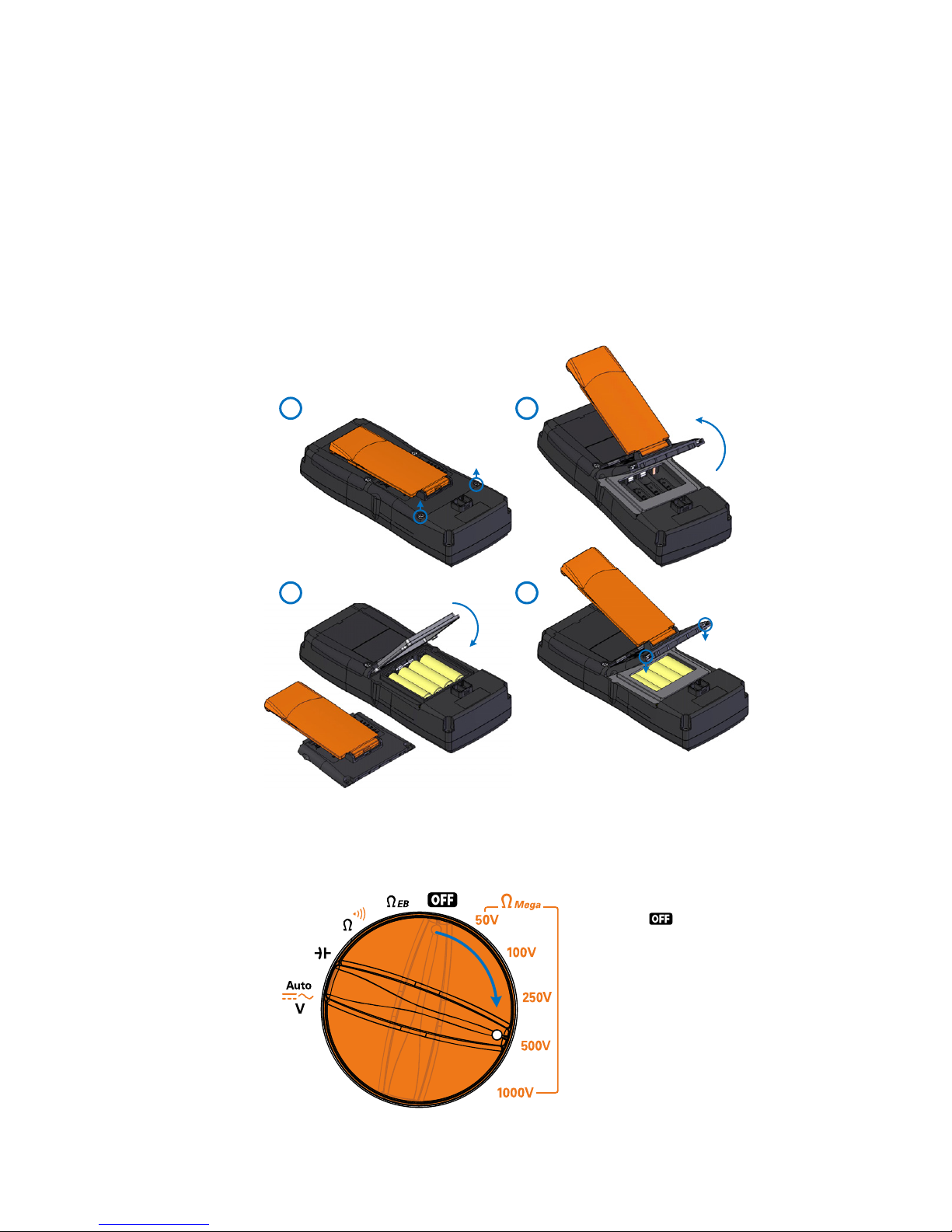
Install or Change the Batteries
Install or Change the Batteries
The tester is powered by four 1.5 V AA alkaline batteries
(included in the shipment).
Before installing or changing the batteries, pull from a corner
and stretch the orange rubber holster to remove it.
Turn On the Tester
2 U1452A/U1452AT/U1451A Quick Start Guide
Turn the rotary switch
from the position
to any other position
to begin making
measurements.
Page 5
U1452A/U1452AT/U1451A Insulation Tester
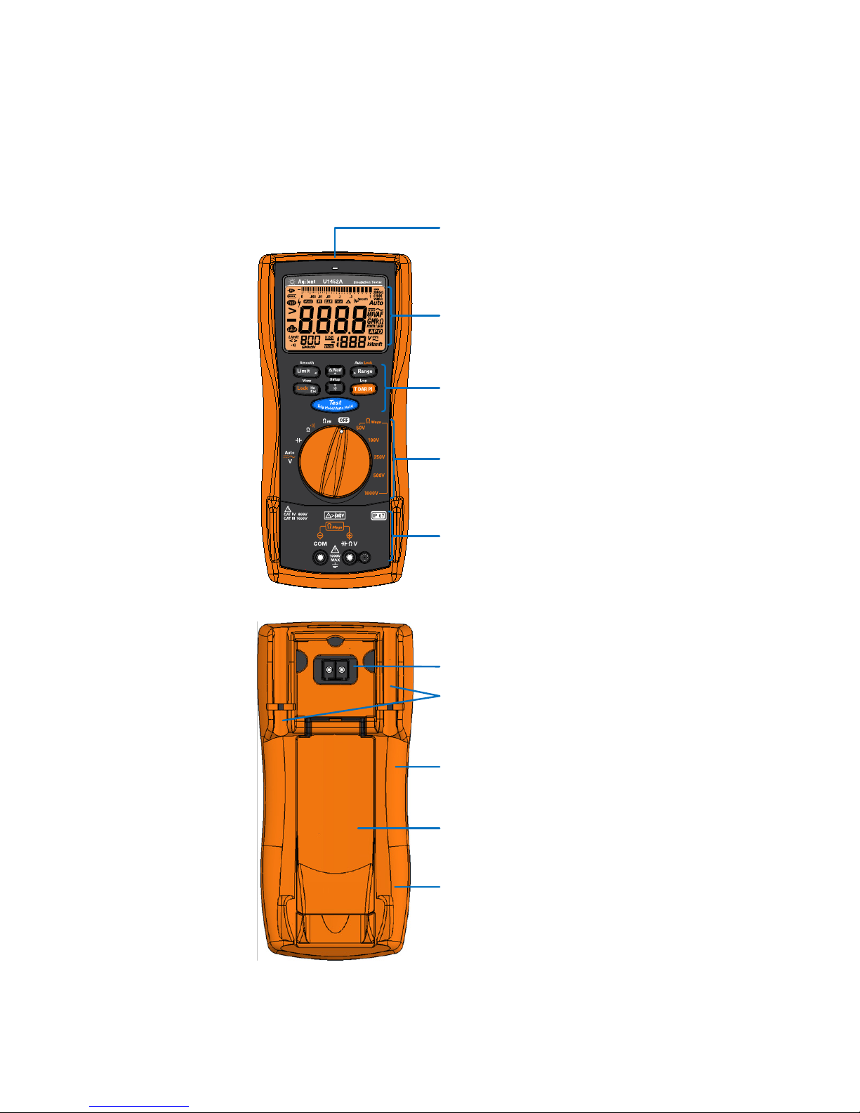
Red LED indicator
Keypad
Rotary switch
Fuse access
Tilt stand
Display screen
Input terminals
Test lead/probe holders
IR communication port
(Under the orange rubber holster)
Battery access
(Under the orange rubber holster)
The Tester at a Glance
The Tester at a Glance
U1452A/U1452AT/U1451A Quick Start Guide 3
Page 6
U1452A/U1452AT/U1451A Insulation Tester
NOTE
WARNING
Using the Rotary Switch
Using the Rotary Switch
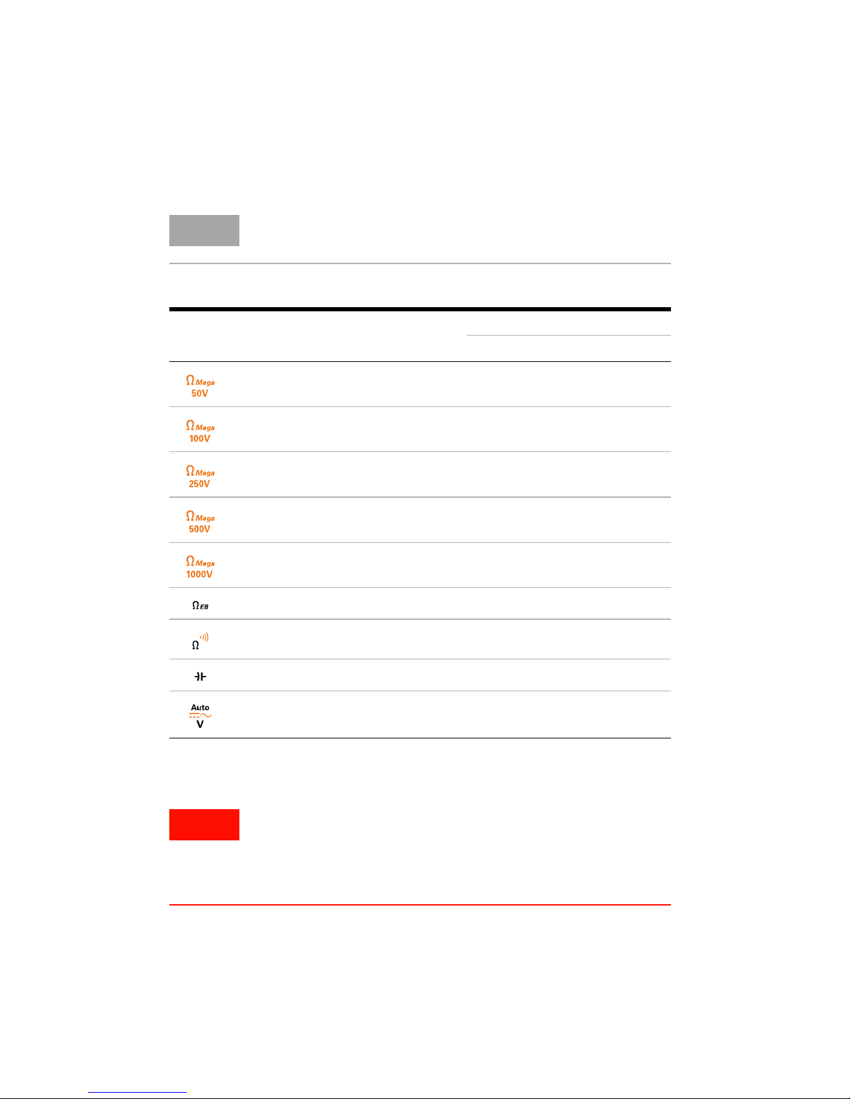
Press [T DAR PI] to select the alternate measurement function(s) or test methods for insulation resistance tests.
Legend Measurement function
50 V insulation resistance test,
T, DAR, PI
100 V insulation resistance test,
T, DAR, PI
250 V insulation resistance test,
T, DAR, PI
500 V insulation resistance test,
T, DAR, PI
1000 V insulation resistance test,
T, DAR, PI
Earth-bond resistance, T
Resistance, Continuity
Capacitance
Auto (V), DC V, AC V
[1]
[1]
[1]
[1]
[1]
Model
U1452A U1452AT U1451A
✔✔
✔✔
✔
✔
✔
-
-
-
-
-
✔
✔
✔
✔✔✔
✔✔✔
✔✔✔
✔✔✔
[1]
DAR and PI tests for models U1452A and U1452AT only.
Remove the test leads from the measuring source or target
before changing the rotary switch position.
Refer to the U1452A/U1452AT/U1451A User’s Guide for a
complete list and description of all rotary switch labels.
4 U1452A/U1452AT/U1451A Quick Start Guide
Page 7
Using the Keypad
U1452A/U1452AT/U1451A Insulation Tester
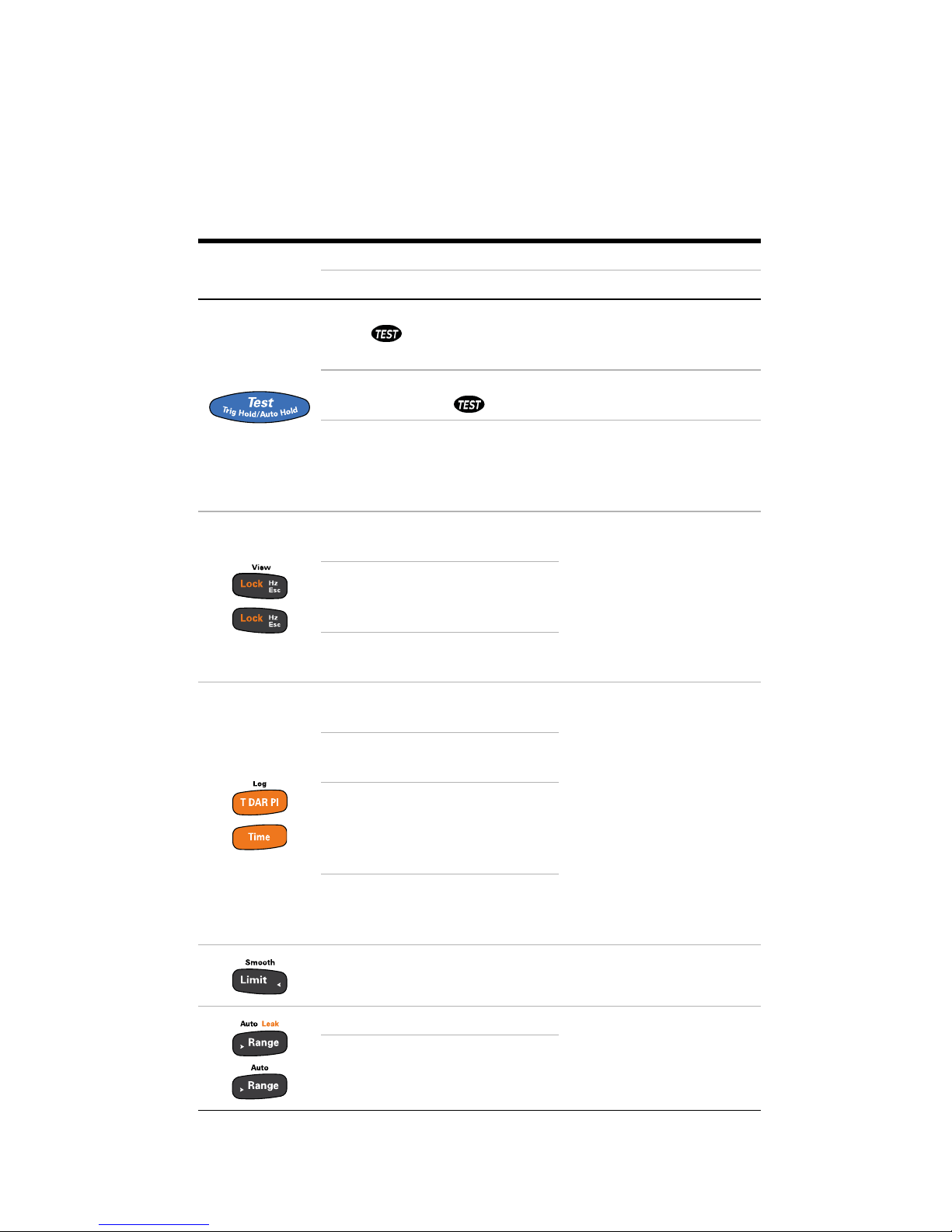
Using the Keypad
Legend
Key response when pressed for:
Less than 1 second More than 1 second
IR Test: Initiates an insulation test
[1]
as long as [Te s t ] is
held ( is shown) — the tester sources (outputs) a high
voltage and measures insulation resistance
EBR Test: Initiates an earth-bond resistance test
[2]
as long
as [Te s t] is held ( is shown)
Auto Hold: Automatically
Trig Hold: Freezes the present
reading in the display
[3]
freezes the present reading once the reading is
[3]
stable
Lock: Locks the insulation test
or earth-bond resistance test
Hz: Displays the frequency
(when the rotary switch is in
the V position)
[4]
View (U1452A and
U1452AT): Enters the Log
review menu
Esc: Discards the changes
made in the Setup menu
Selects the alternate measurement function(s)
T/Time: Configures the tester
for a timed test
DAR (U1452A and U1452AT):
Configures the tester for a
dielectric absorption ratio
[1][5]
test
[4][5]
Log (U1452A and
U1452AT): Starts the data
Log
PI (U1452A and U1452AT):
Configures the tester for a
polarization index test
Limit: Enables Limit comparison
[1][5]
Smooth: Enables Smooth
Range: Sets a manual range
Auto: Enables autorang-
Leak (U1452A and U1452AT):
Displays the leakage current
[4]
ing
U1452A/U1452AT/U1451A Quick Start Guide 5
Page 8
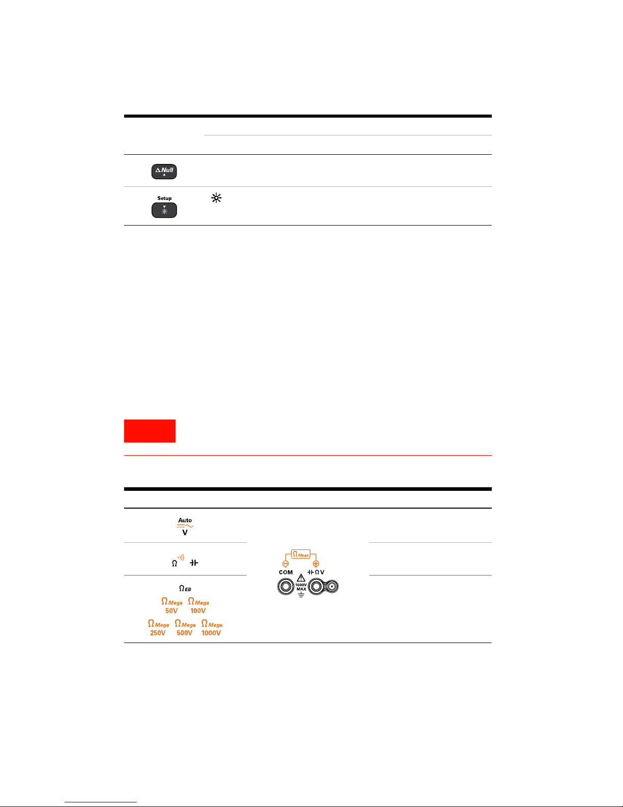
U1452A/U1452AT/U1451A Insulation Tester
WARNING
Using the Input Terminals
Legend
Key response when pressed for:
Less than 1 second More than 1 second
Null: Enables Null -
: Enable or disable the LCD
backlight
[1]
When the rotary switch is in one of the Ω
[2]
When the rotary switch is in the Ω EB position.
[3]
When the rotary switch is NOT in one of the Ω
[4]
When the rotary switch is in one of the Ω
[5]
Press [Te s t] to start the test.
Using the Input Terminals
Setup: Enters the Setup
menu
position.
Mega
or the Ω EB position.
Mega
or the Ω EB position.
Mega
To avoid damaging this device, do not exceed the input limit.
Rotary position Input terminals Overload protection
1000 Vrms
1000 Vrms for
short circuit <0.3 A
440 mA/1000 V, 30 kA
fast-acting fuse
6 U1452A/U1452AT/U1451A Quick Start Guide
Page 9
U1452A/U1452AT/U1451A Insulation Tester
CAUTIONCAUTION
3
2
1
Select a
test voltage
Remote
Switch
Probe
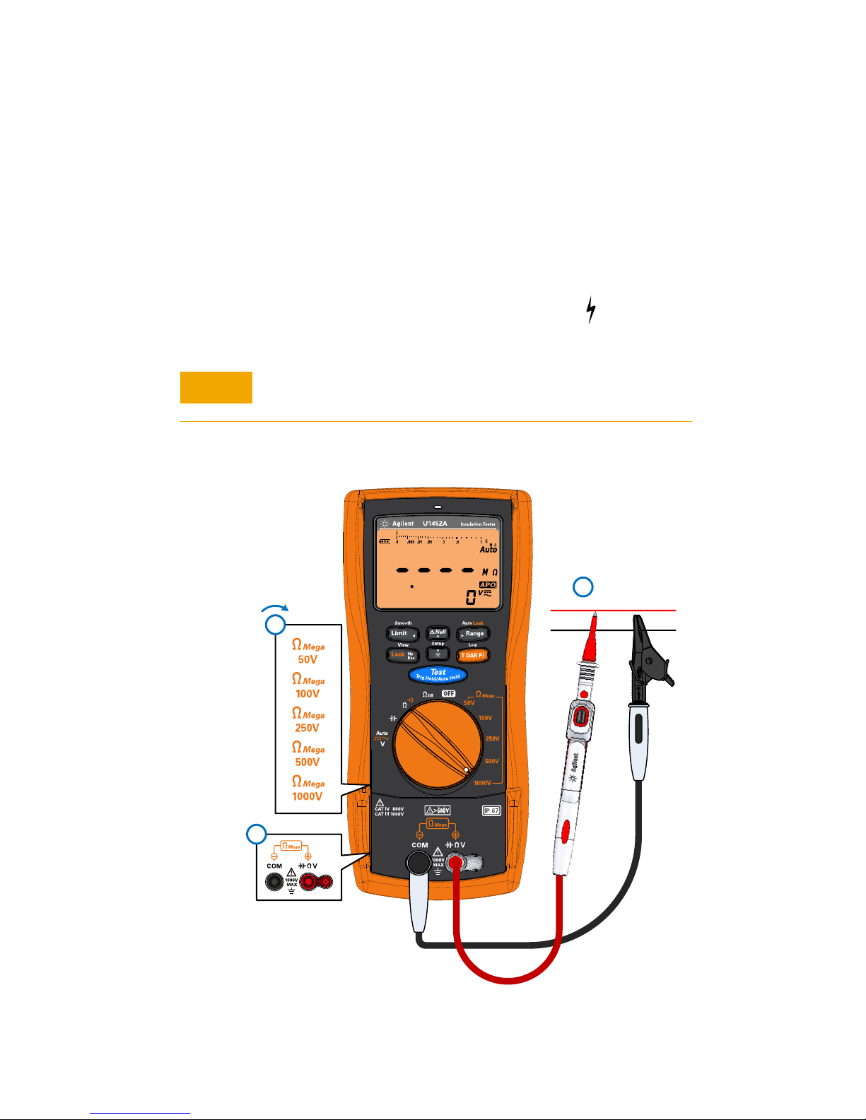
Insulation Resistance (IR) Test
Insulation Resistance (IR) Test
Ensure that the device-under-test (DUT) is de-energized before
performing any resistance measurement.
The tester automatically detects if the circuit is energized. If
the external voltage is detected to be greater than 30 V, the
test is inhibited and the voltage hazard symbol ( ) is shown on
the display.
DO NOT perform insulation resistance test in distribution systems with voltages higher than 600 V.
U1452A/U1452AT/U1451A Quick Start Guide 7
Page 10
U1452A/U1452AT/U1451A Insulation Tester
4
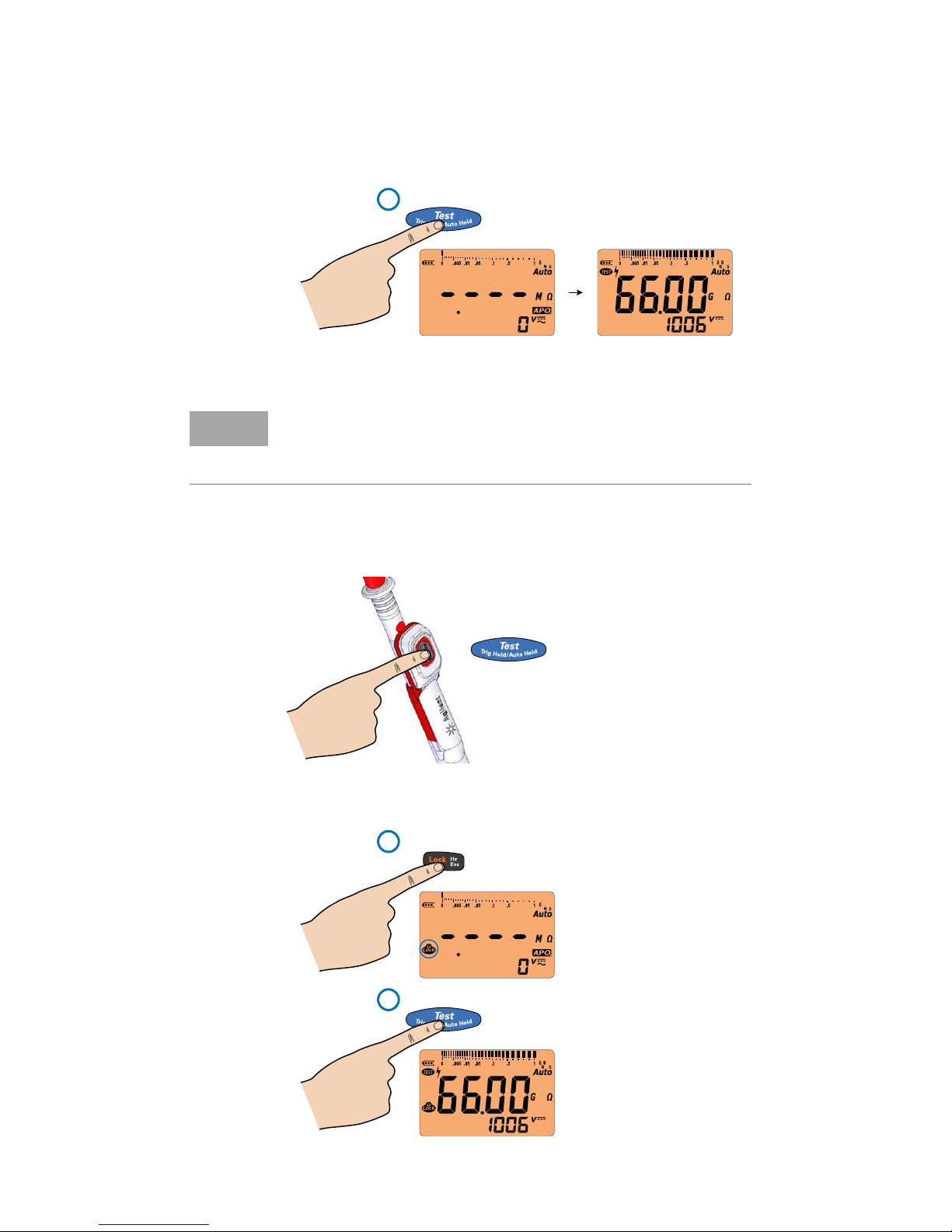
Test will continue until
[Te s t] is released.
Hold
NOTE
=
2
1
Press [Te s t] or [Lock]
again to unlock and
stop the test.
Press once
Insulation Resistance (IR) Test
When an insulation test is in progress, the red LED indicator at
the top of the tester will blink every 2 seconds (if the Limit
function is not enabled).
Using the Remote Switch Probe
Locking the Test for IR/EBR Tests
8 U1452A/U1452AT/U1451A Quick Start Guide
Page 11
U1452A/U1452AT/U1451A Insulation Tester
1
2
3
OR
NOTE
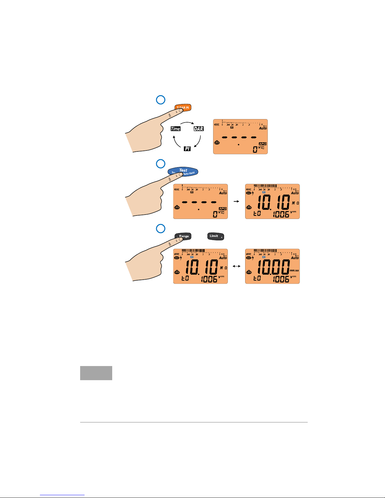
Performing PI/DAR/T Tests
Insulation Resistance (IR) Test
Polarization Index (PI) = IR
10 minutes
Dielectric Absorption Ratio (DAR) = IR
(default; can be changed to IR
Timed (T) = IR
•Press [Range] or [Limit] to toggle the display between the
1 minute
(default; can be changed in Setup)
60 seconds
/IR
1 minute
60 seconds
/IR
15 seconds
/IR
30 seconds
in Setup)
timer and the measured value during PI, DAR, or T tests.
• Err is shown on the display if the IR is greater than the
maximum range or less than 0.001 MΩ after t1/t15/t30; if
the test is interrupted by the user; or if the tester’s battery is
low.
U1452A/U1452AT/U1451A Quick Start Guide 9
Page 12
U1452A/U1452AT/U1451A Insulation Tester
NOTE
Insulation Resistance (IR) Test
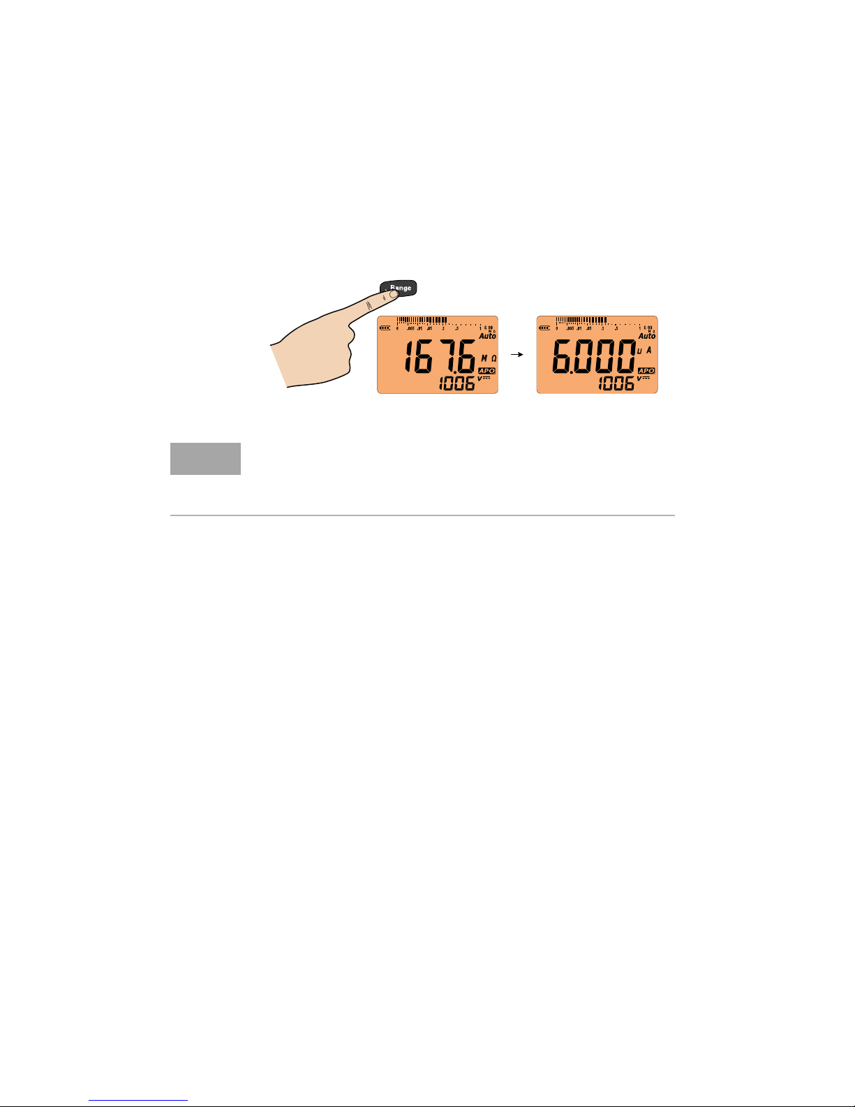
Viewing Leakage Current
Press [Range] after the IR test to view the leakage current; or
press [Range] during the IR test to view the leakage current if
the IR test is locked (see page 8).
Viewing the leakage current for DAR, PI, or T tests:
Press [Range] first before selecting the PI, DAR, or T test.
Then, press [Test] to view leakage current.
10 U1452A/U1452AT/U1451A Quick Start Guide
Page 13
U1452A/U1452AT/U1451A Insulation Tester
CAUTIONCAUTION
3
2
1
Remote
Switch
Probe
4
>
Hold
OR
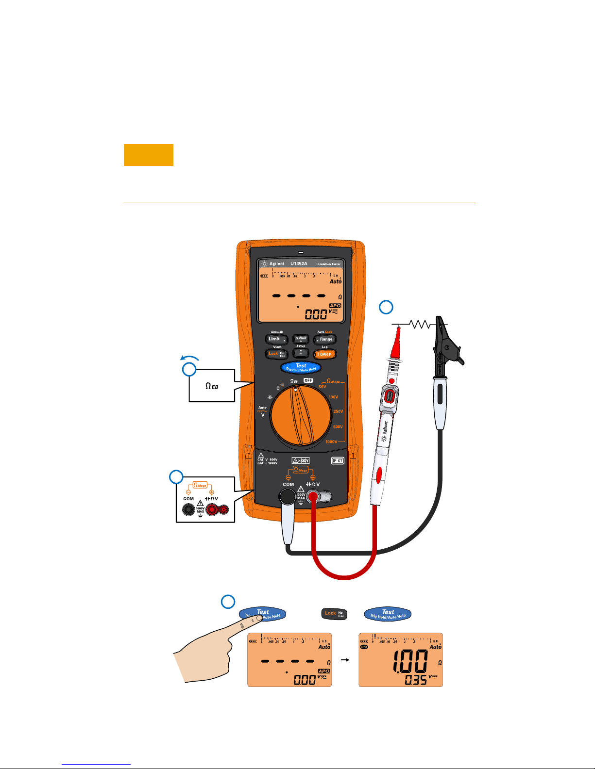
Earth-Bond Resistance (EBR) Test
Earth-Bond Resistance (EBR) Test
The tester automatically detects if the circuit is energized. If
the external voltage is detected to be greater than 2 V, the test
is inhibited. Disconnect the tester and remove power from the
circuit before proceeding.
U1452A/U1452AT/U1451A Quick Start Guide 11
Page 14
U1452A/U1452AT/U1451A Insulation Tester
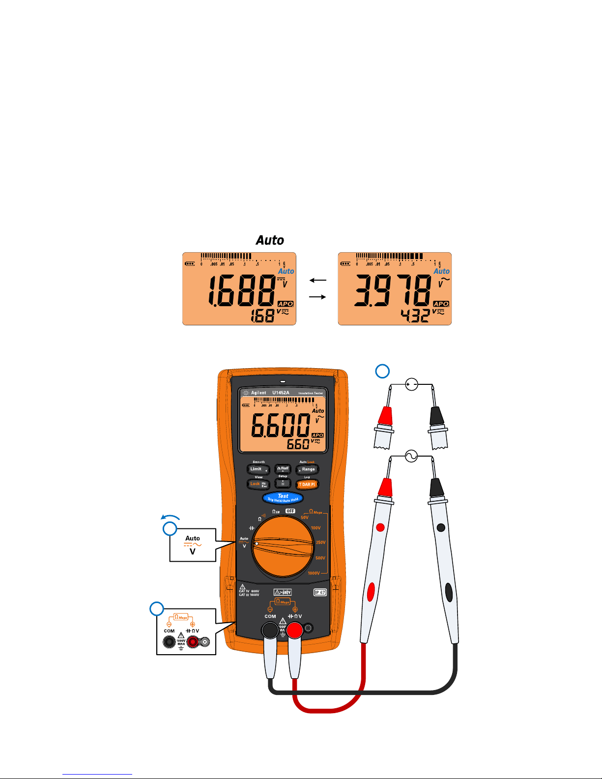
The symbol blinks during the identification
DC
AC
The AC+DC value is shown in the secondary display
AC
3
DC
2
1
Voltage Measurements
Voltage Measurements
The Auto function is able to automatically
• Identify the signal component (AC or DC) of an electrical
source to be indicated on the primary display, and
• Select a suitable measurement range according to the
AC+DC reading
12 U1452A/U1452AT/U1451A Quick Start Guide
Page 15
U1452A/U1452AT/U1451A Insulation Tester
3
2
1
2
1
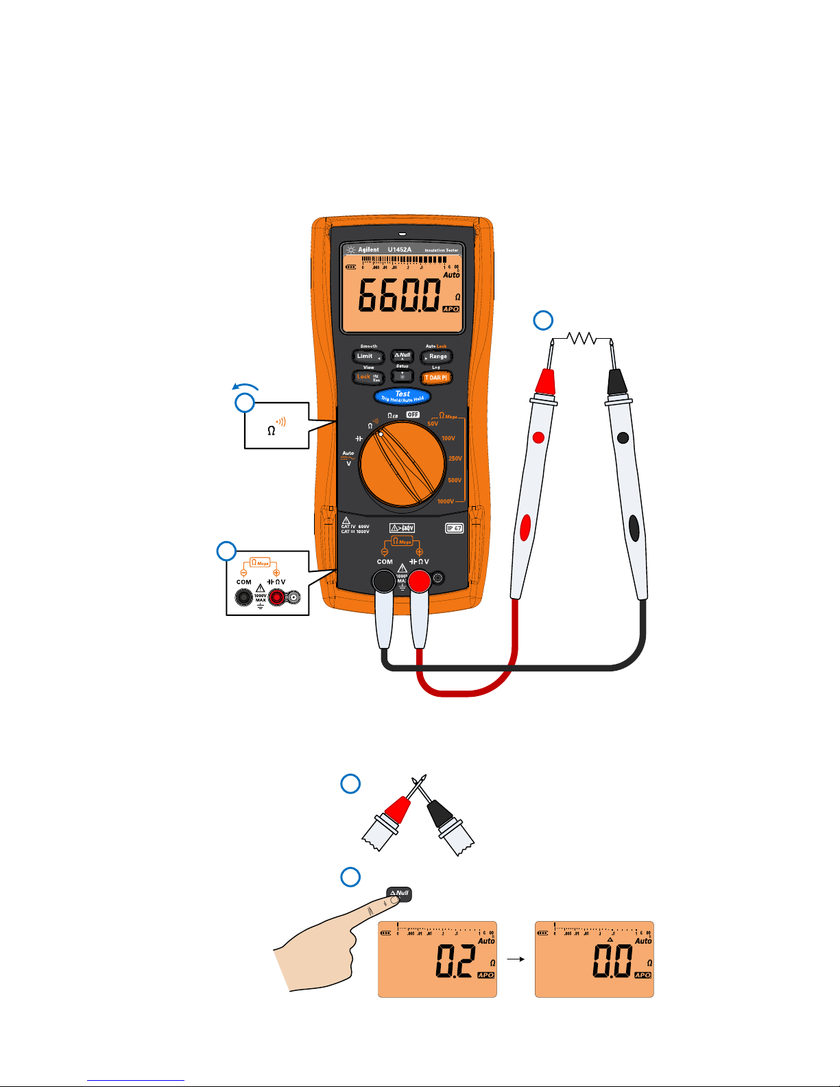
Resistance Measurement
Resistance Measurement
Removing Test Lead Resistance
U1452A/U1452AT/U1451A Quick Start Guide 13
Page 16
U1452A/U1452AT/U1451A Insulation Tester
CAUTIONCAUTION
2
1
3
ON
(closed)
OFF
(open)
4
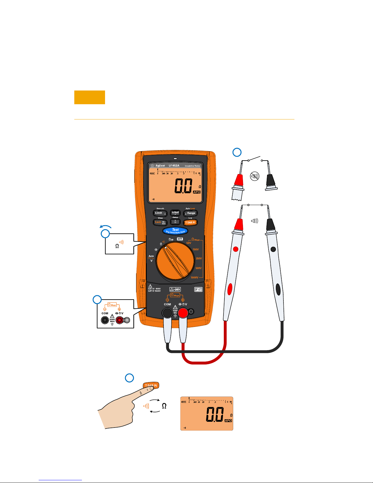
Continuity Test
Continuity Test
To avoid possible damage to your tester or to the equipment
under test, disconnect the circuit power and discharge all
high-voltage capacitors before performing continuity tests.
14 U1452A/U1452AT/U1451A Quick Start Guide
Page 17
U1452A/U1452AT/U1451A Insulation Tester
CAUTIONCAUTION
1
3
+
–
2
NOTE
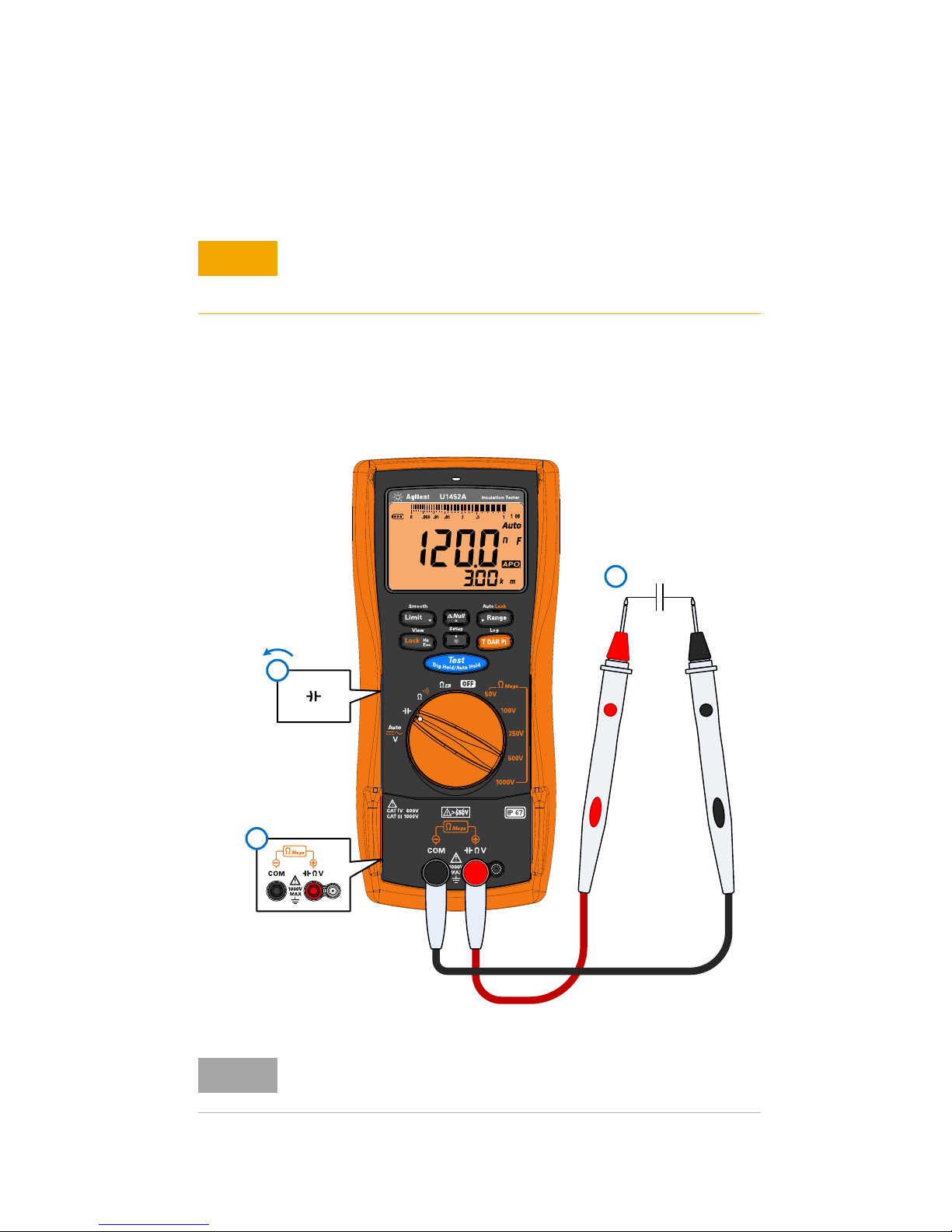
Capacitance Measurement
To avoid possible damage to the tester or to the equipment
under test, disconnect circuit power and discharge all
high-voltage capacitors before measuring capacitance.
Before proceeding with capacitance measurements, first use
the DC V function to confirm that the capacitor is fully
discharged.
Capacitance Measurement
The cable length equivalent of the circuit under test is shown
in the secondary display. The default scale is 1 km per 40 nF.
U1452A/U1452AT/U1451A Quick Start Guide 15
Page 18

U1452A/U1452AT/U1451A Insulation Tester
Capacitance Measurement
THIS PAGE HAS BEEN INTENTIONALLY LEFT BLANK.
16 U1452A/U1452AT/U1451A Quick Start Guide
Page 19
Contacting Keysight
CAUTIONCAUTION
WARNING
CAT III
1000 V
CAT IV
600 V
You can contact Keysight Technologies at one of the following telephone
numbers for warranty, service, or technical support information:
• In the United States: +1 800 829-4444
• In Canada: +1 877 894-4414
• In China: 800-810-0189
• In Europe: 31 20 547 2111
• In Japan: 0120-421-345
Or use our Web link for information on contacting Keysight worldwide:
www.keysight.com/find/assist
Or contact your Keysight Technologies Representative.
Safety Notices
A CAUTION notice denotes
a hazard. It calls attention
to an operating procedure,
practice, or the like that, if
not correctly performed or
adhered to, could result in
damage to the product or
loss of important data. Do
not proceed beyond a CAU-
TION notice until the indicated conditions are fully
understood and met.
A WARNING notice
denotes a hazard. It calls
attention to an operating
procedure, practice, or the
like that, if not correctly
performed or adhered to,
could result in personal
injury or death. Do not proceed beyond a WARNING
notice until the indicated
conditions are fully understood and met.
EMC designed in compliance with IEC
61326-1:2005/EN 61326-1:2006. Use with
standard or compatible test probes.
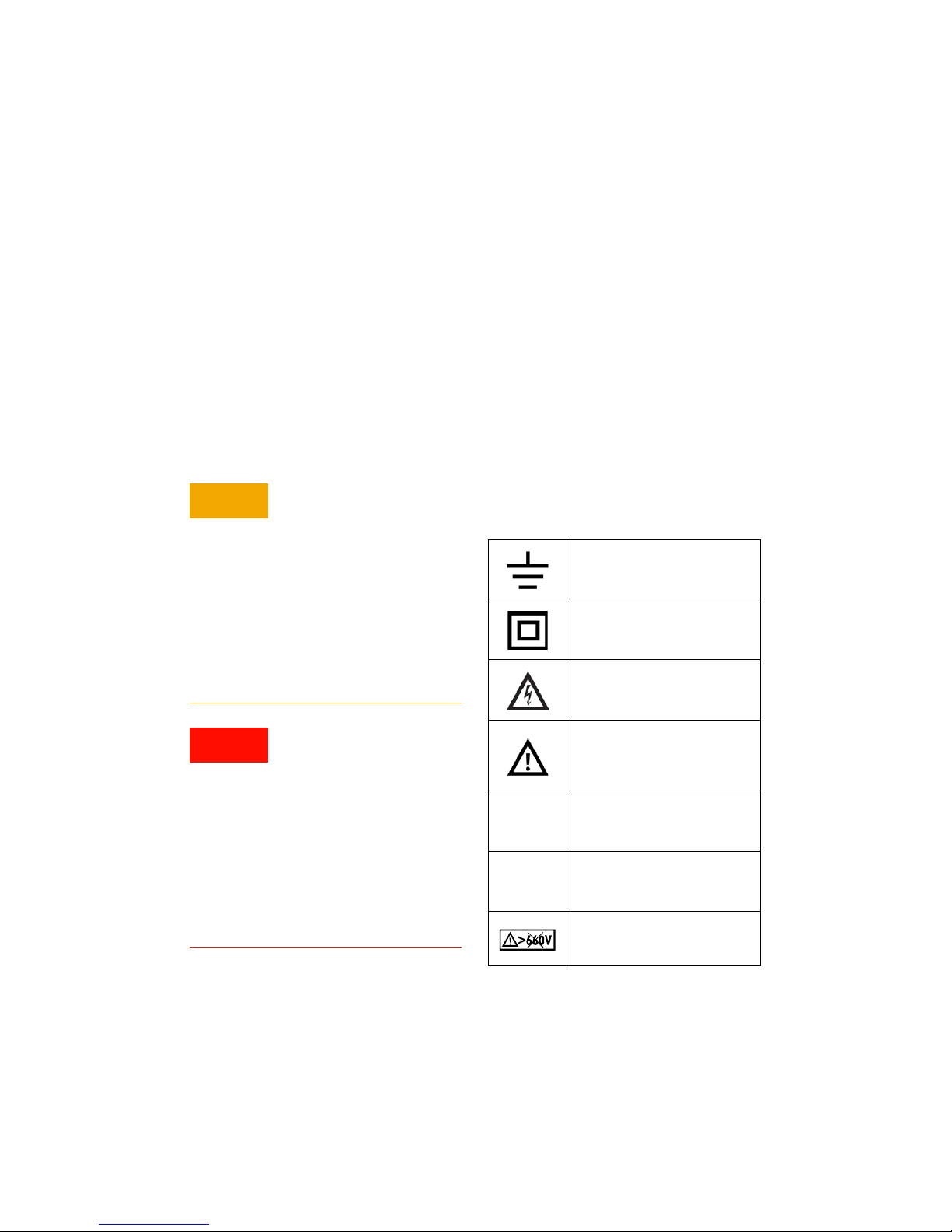
Safety Symbols
Earth (ground) terminal
Equipment protected
throughout by double insulation or reinforced insulation
Caution, risk of electric
shock
Caution, risk of danger (refer
to the instrument manual for
specific Warning or Caution
information)
Category III 1000 V overvoltage protection
Category IV 600 V overvoltage protection
Do not use in distribution
systems with voltages
higher than 600 V
Safety and EMC Information
This meter is safety-certified in compliance
with IEC/EN 61010-1:2010 for Category III
1000 V and Category IV 600 V; and IEC/EN
61557-1, IEC/EN 61557-2, IEC/EN 61557-4.
For more details on any information not found in this document, refer to the
Keysight U1452A/U1452AT/U1451A Insulation Tester User’s Guide
Page 20

This information is subject to change without notice.
© Keysight Technologies 2013, 2014
Edition 2, August 2014
*U1451-90001*
U1451-90001
www.keysight.com
 Loading...