

Page 1

Keysight U1401B
Handheld Multi-Function
Calibrator/Meter
Quick Start
Guide
Page 2
Contacting Keysight
www.keysight.com/find/assist
(worldwide contact information for
repair and service)
Safety and EMC Information
This instrument is safety and EMC
certified in compliance with:
– IEC 61010-1:2001/
EN61010-1:2001 (2nd Edition)
– Canada: CAN/CSA-C22.2 No.
61010-1-04
– USA: ANSI/UL 61010-1:2004
– IEC61326-2-1:2005/
EN61326-2-1:2006
– Canada: ICES-001:2004
– Australia/New Zealand: AS/NZS
CISPR11:2004
Measurement Category II 150 V,
Pollution Degree 2. Use with
standard or compatible test probes.
Safety Notices
CAUTION
A CAUTION notice denotes a
hazard. It calls attention to an
operating procedure, practice, or
the like that, if not correctly
performed or adhered to, could
result in damage to the product or
loss of important data. Do not
proceed beyond a CAUTION notice
until the indicated conditions are
fully understood and met.
WARNING
A WARNING notice denotes a
hazard. It calls attention to an
operating procedure, practice, or
the like that, if not correctly
performed or adhered to, could
result in personal injury or
death. Do not proceed beyond a
WARNING notice until the
indicated conditions are fully
understood and met.
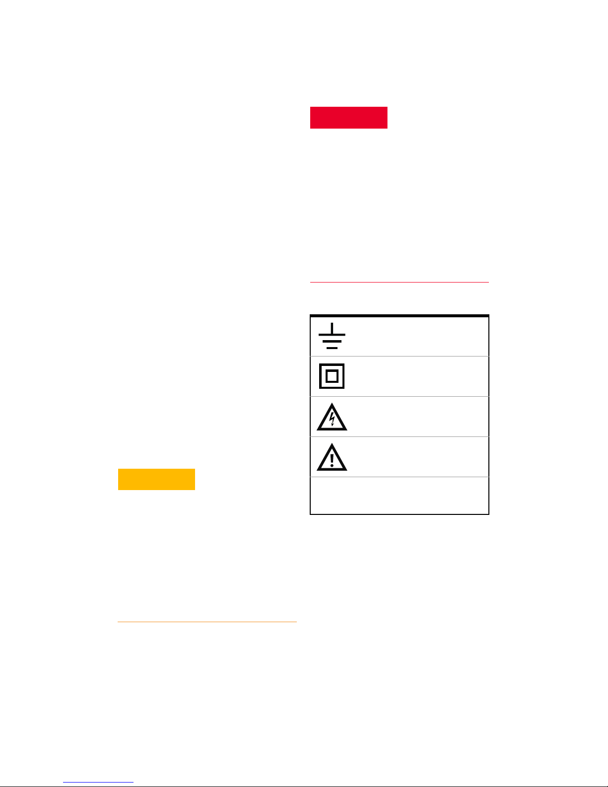
Safety symbols
Earth (ground) terminal
Double insulation
Caution, risk of electric
shock
Caution, risk of danger
CAT II
150V
Category II 150 V
overvoltage protection
2 Keysight U1401B Quick Start Guide
For further safety information details, refer to the
Keysight U1401B Handheld Multi-Function Calibrator/Meter User’s Guide.
Page 3

Keysight U1401B Quick Start Guide 3
Table of Contents
Recharging the Batteries . . . . . . . . . . . . . . . . . 6
Functions and Features . . . . . . . . . . . . . . . . . . . 8
Input/Output Terminals and Overload
Protection . . . . . . . . . . . . . . . . . . . . . . . . . . 10
Charging the battery . . . . . . . . . . . . . . . . . . . . 11
Performing Voltage Measurements . . . . . . . . 12
Performing Current Measurements . . . . . . . . 14
Performing Resistance Measurement and
Continuity Test . . . . . . . . . . . . . . . . . . . . . . . 16
Performing Temperature Measurements . . . . 18
Frequency and Frequency Counter
Measurements . . . . . . . . . . . . . . . . . . . . . . . 20
Square Wave Output . . . . . . . . . . . . . . . . . . . . 22
Tilt Stand . . . . . . . . . . . . . . . . . . . . . . . . . . . . . 23
Page 4

4 Keysight U1401B Quick Start Guide
THIS PAGE HAS BEEN INTENTIONALLY LEFT BLANK.
Page 5
Keysight U1401B Quick Start Guide 5
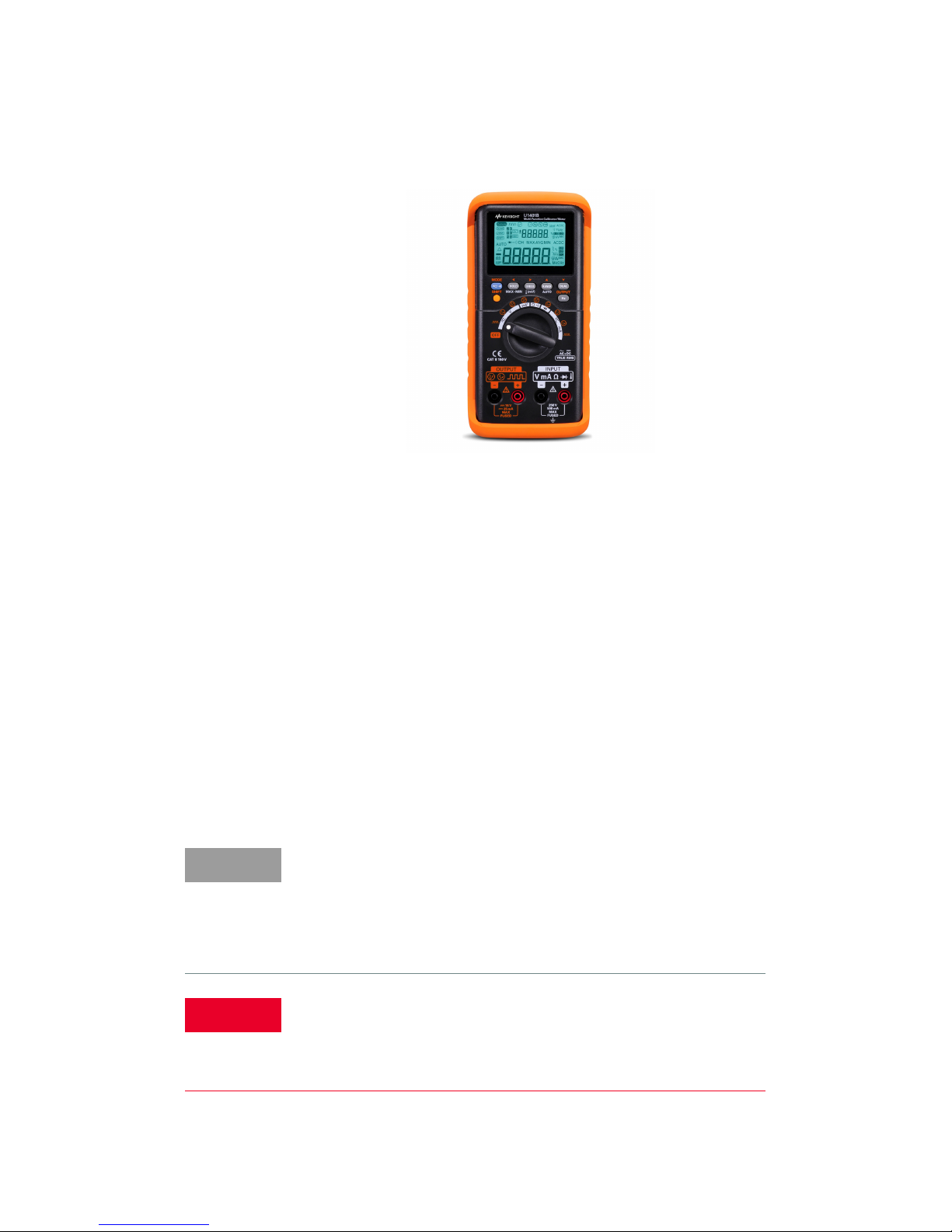
The following items are included with your
multimeter:
✔ Protective holster
✔ Rechargeable battery pack (1.2 V NiMH AA
×
8)
✔ Power cord and AC power adapter
✔ Silicone test leads, alligator clips, and a
yellow test lead for mA simulation
✔ Certificate of calibration
✔ Printed Quick Start Guide
If anything is missing or damaged, please contact
the nearest Keysight Sales Office.
NOTE
Your multimeter is capable of remote data logging.
To use this feature, you will need an IR-USB cable
(U5481A, purchased separately) and the Keysight
GUI Data Logger Software (downloadable from
www.keysight.com/find/hhTechLib).
WARNING
Ensure the terminal connections are correct for that
particular measurement selection before starting any
measurement. To avoid damage to the device, do not
exceed the input limit.
Page 6
6 Keysight U1401B Quick Start Guide
Recharging the Batteries
Charge the batteries immediately when the low
battery annunciator starts flashing. It is strongly
recommended that you use only the specified
type of 24 V AC adapter to charge these
rechargeable batteries.
1 Power down the instrument and disconnect
all the test leads from the terminals.
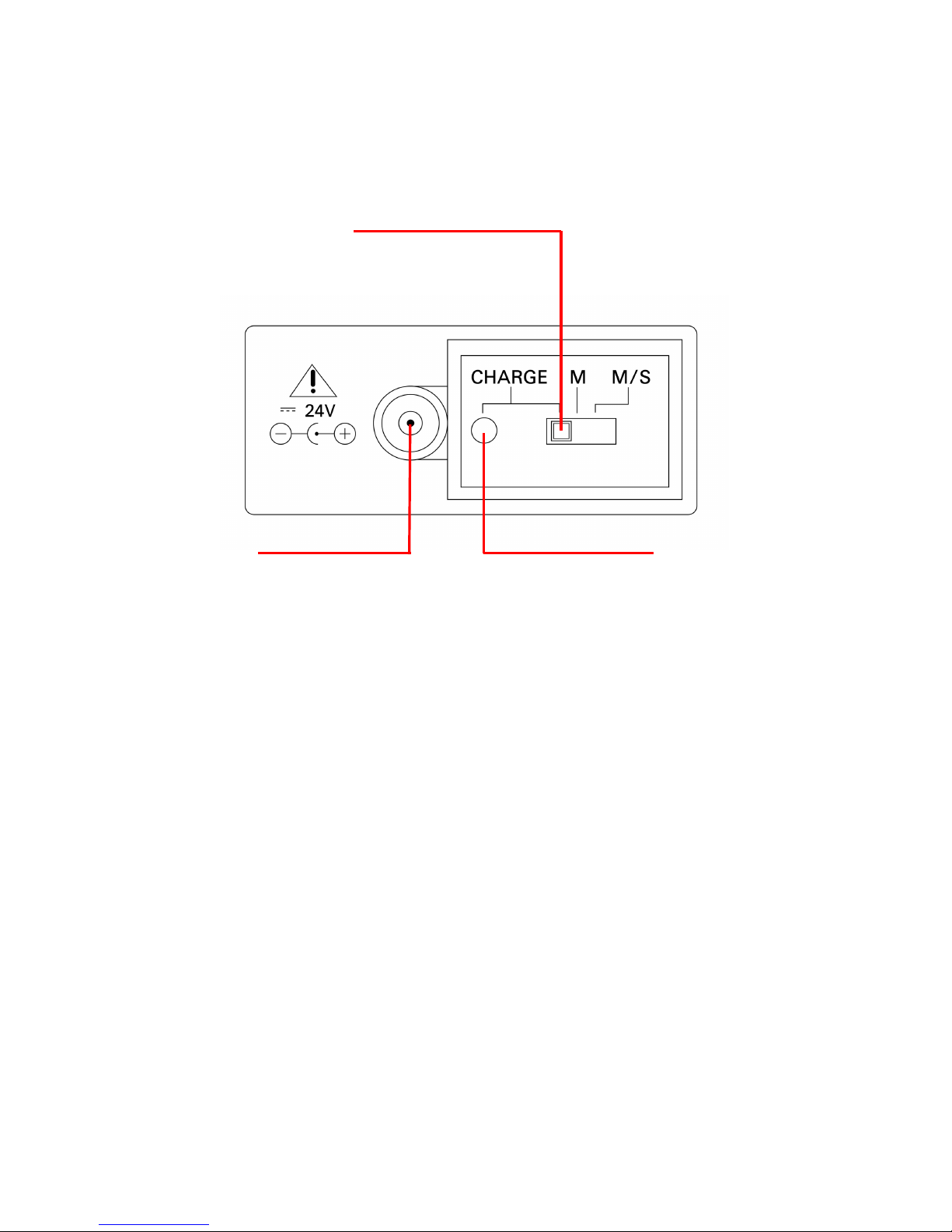
2 Plug the AC adapter into the jack on the side
panel.
3 Set the slide switch at the CHARGE position.
4 The red light indicates that the batteries are
being recharged.
Set slide switch at the
CHARGE position
Charging indication
Green: Fully charged
Red: Charging
External AC
adapter jack
Page 7

Keysight U1401B Quick Start Guide 7
5 When the batteries have been fully recharged,
the green light turns on. Remove the AC
adapter and set the slide switch at the M or
M/S position.
WARNING
Do not discharge a battery by shorting it or subjecting
it to reverse polarity. Do not mix different types of
battery. Make sure a battery is rechargeable before
charging it.
CAUTION
Do not turn the rotary switch while the instrument is
being recharged because a DC 24 V supply is
applied to the charging terminal.
Page 8
8 Keysight U1401B Quick Start Guide
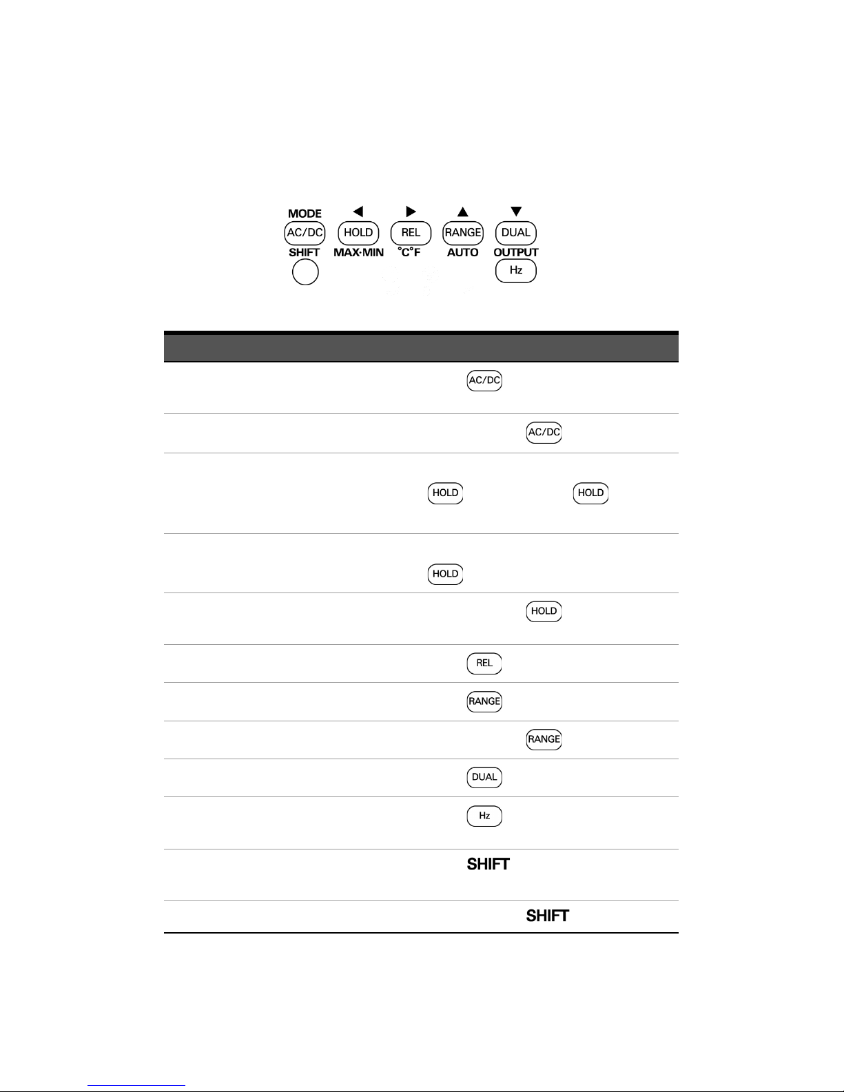
Functions and Features
Action Steps
Selects AC, DC, or AC+DC
measurement
Press
Toggles peak hold mode on and off
Press and hold for > 1 s
Freezes the measured value With data hold mode enabled, press
. Press and hold for > 1 s
to exit.
Enters or exits the refresh hold mode With refresh hold mode enabled, press
Enters or exits the dynamic recording
mode
Press and hold for > 1 s
Offsets the measured value
Press
Selects the measurement range
Press
Turns on autorange
Press and hold for > 1 s
Turns on dual display
Press
Turns on the frequency measurement
function
Press
Enables the shifted functions of the
keypad
Press
Toggles the backlight on or off
Press and hold for > 1 s
Page 9
Keysight U1401B Quick Start Guide 9
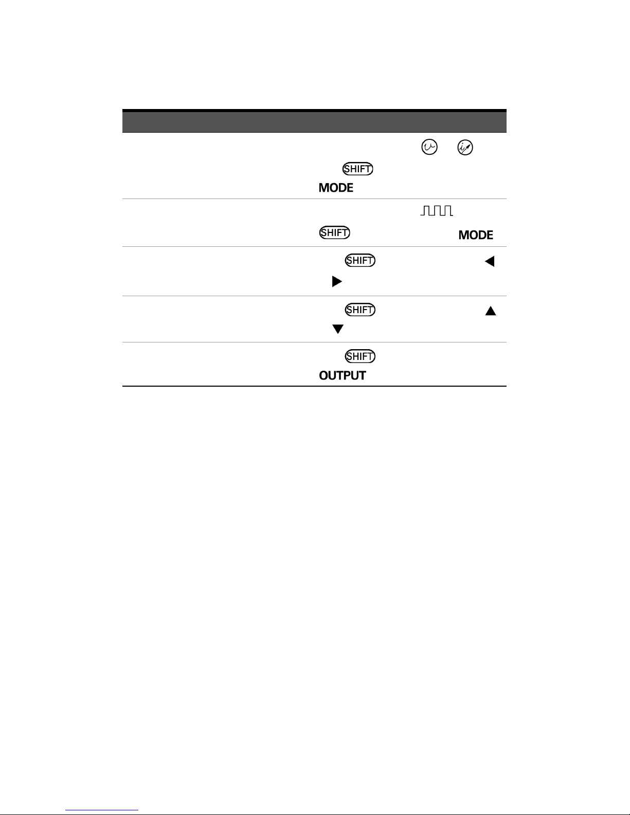
Selects output mode and range for
voltage and current output
With rotary switch at or , and
with mode enabled, press
Selects parameter adjustments for
square wave output
With rotary switch at , and with
mode enabled, press
Selects a digit or the polarity to be
adjusted
With mode enabled, press
or
Adjusts a digit or the polarity
With mode enabled, press
or
Toggles the output state on and off
With mode enabled, press
Action Steps
Page 10
10 Keysight U1401B Quick Start Guide
Input/Output Terminals and Overload
Protection
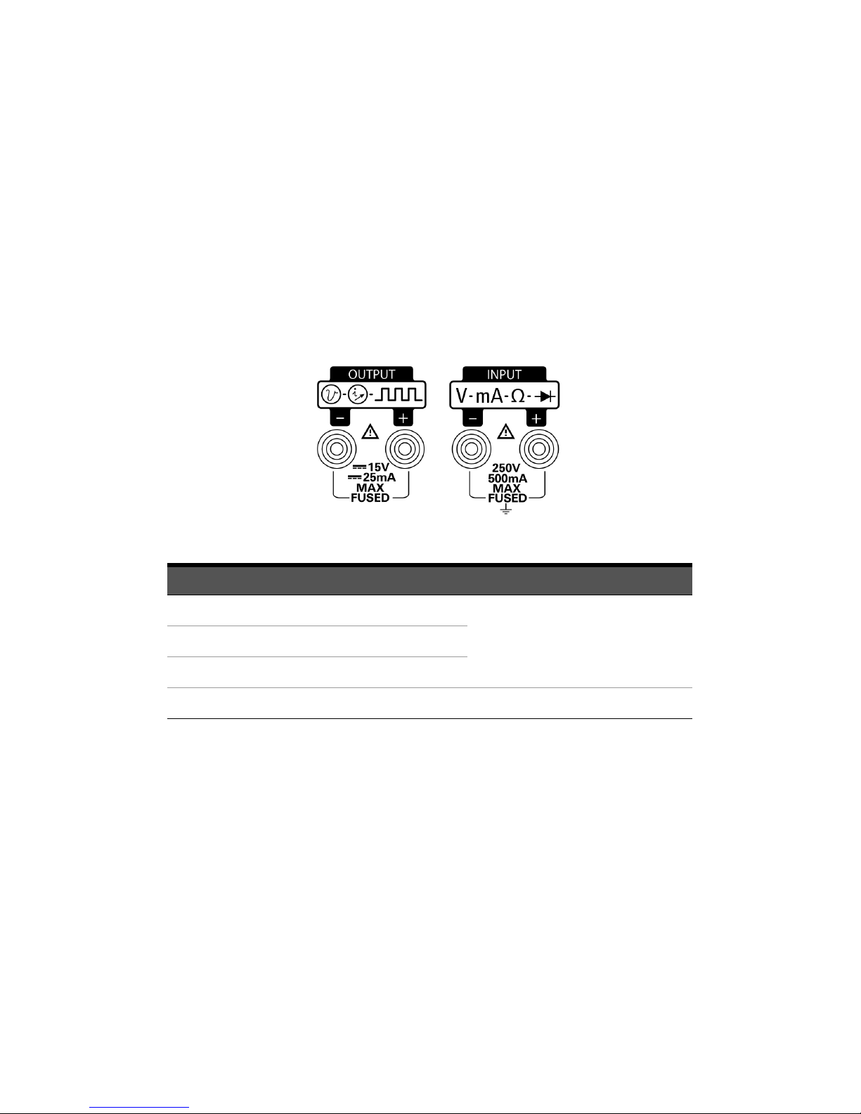
The output terminals are protected with DC 30 V
overload protection. The overload protection
limits of the input terminals are shown in the table
below
Functions Overload Protection
AC/DC voltage measurement 250 Vrms
Resistance measurement and continuity test
Temperature measurement
AC/DC current measurement 250 V/630 mA, fast-acting fuse
Page 11

Keysight U1401B Quick Start Guide 11
Charging the battery
A new rechargeable battery comes in a
discharged condition and must be charged before
use (refer to the U1401B User's and Service Guide
for charging instructions). Upon initial use (or
after a prolonged storage period) the
rechargeable battery may require three to four
charge/discharge cycles before achieving
maximum capacity. To discharge, simply run the
multimeter using the rechargeable battery’s
power until it shuts down or until the low battery
warning appears.
In some instances, the multimeter may indicate
that the charging is complete after ten minutes or
so when charging a new rechargeable battery.
This is a normal phenomenon with rechargeable
batteries. Remove the rechargeable battery from
the device, re-insert it and repeat the charging
procedure.
Page 12
12 Keysight U1401B Quick Start Guide
Performing Voltage Measurements
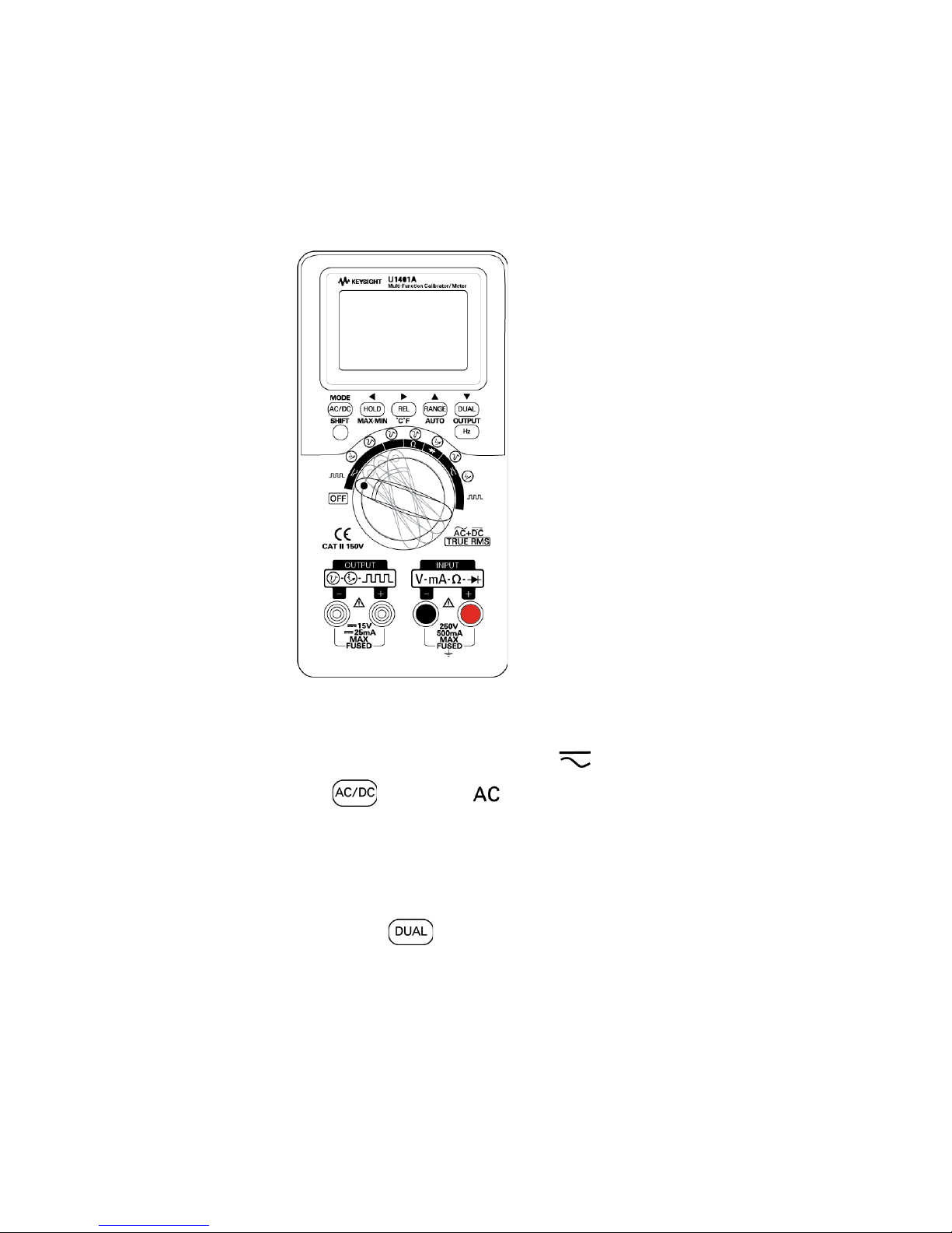
Measuring AC voltage
1 Set the rotary switch to V or mV. Press
to select .
2 Connect the red (+) and black (–) test leads to
the INPUT terminals.
3 Probe the test points and read the display.
4 Press to display dual measurements.
Page 13

Keysight U1401B Quick Start Guide 13
Measuring DC voltage
1 Set the rotary switch to V or mV. Press
to select .
2 Connect the red (+) and black (–) test leads to
the INPUT terminals.
3 Probe the test points and read the display.
4 Press to display dual measurements.
Page 14
14 Keysight U1401B Quick Start Guide
Performing Current Measurements
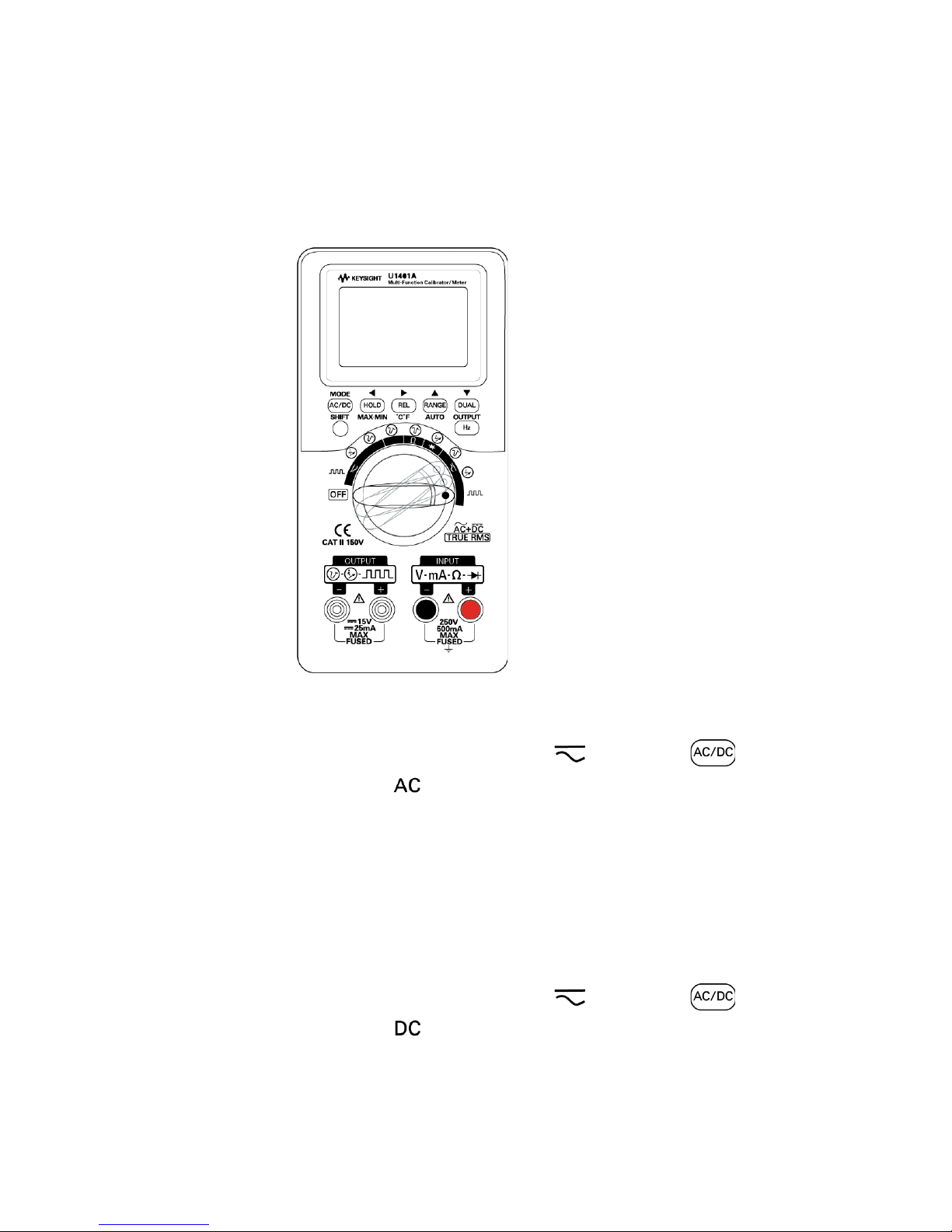
Measuring AC current
1 Set the rotary switch to mA. Press to
select .
2 Connect the red (+) and black (–) test leads to
the INPUT terminals.
3 Probe the test points in series with the circuit
and read the display.
Measuring DC current
1 Set the rotary switch to mA. Press to
select .
2 Connect the red (+) and black (–) test leads to
the INPUT terminals.
Page 15

Keysight U1401B Quick Start Guide 15
3 Probe the test points in series with the circuit
and read the display.
Percentage scale of DC mA measurement
With the rotary switch at mA, another option
selectable with the key is the percentage
scale of DC mA measurement.
Frequency measurement
During AC/DC voltage or AC/DC current
measurement, you can measure the signal
frequency by pressing at any time.
Page 16
16 Keysight U1401B Quick Start Guide
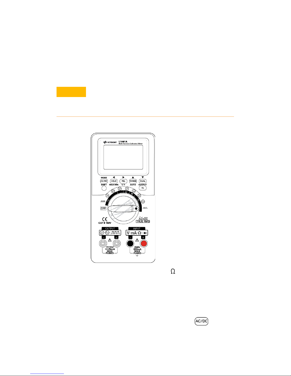
Performing Resistance Measurement and
Continuity Test
1 Set the rotary switch to .
2 Connect the red (+) and black (–) test leads to
the INPUT terminals.
3 Probe the resistor (or shunt) leads and read
the display.
4 To perform continuity test, press to
toggle the audible continuity function on or off.
CAUTION
Disconnect circuit power and discharge all
high-voltage capacitors before measuring
resistance to prevent possible damage to the
instrument or the device under test.
Page 17

Keysight U1401B Quick Start Guide 17
For continuity test, the instrument will beep if the
resistance is less than the values indicated below:
Measurement range Resistance threshold
500.00 Ω 10 Ω
5.0000 kΩ 100 Ω
50.000 kΩ 1 kΩ
500.00 kΩ 10 kΩ
5.0000 MΩ 100 kΩ
50.000 MΩ 1 MΩ
Page 18
18 Keysight U1401B Quick Start Guide
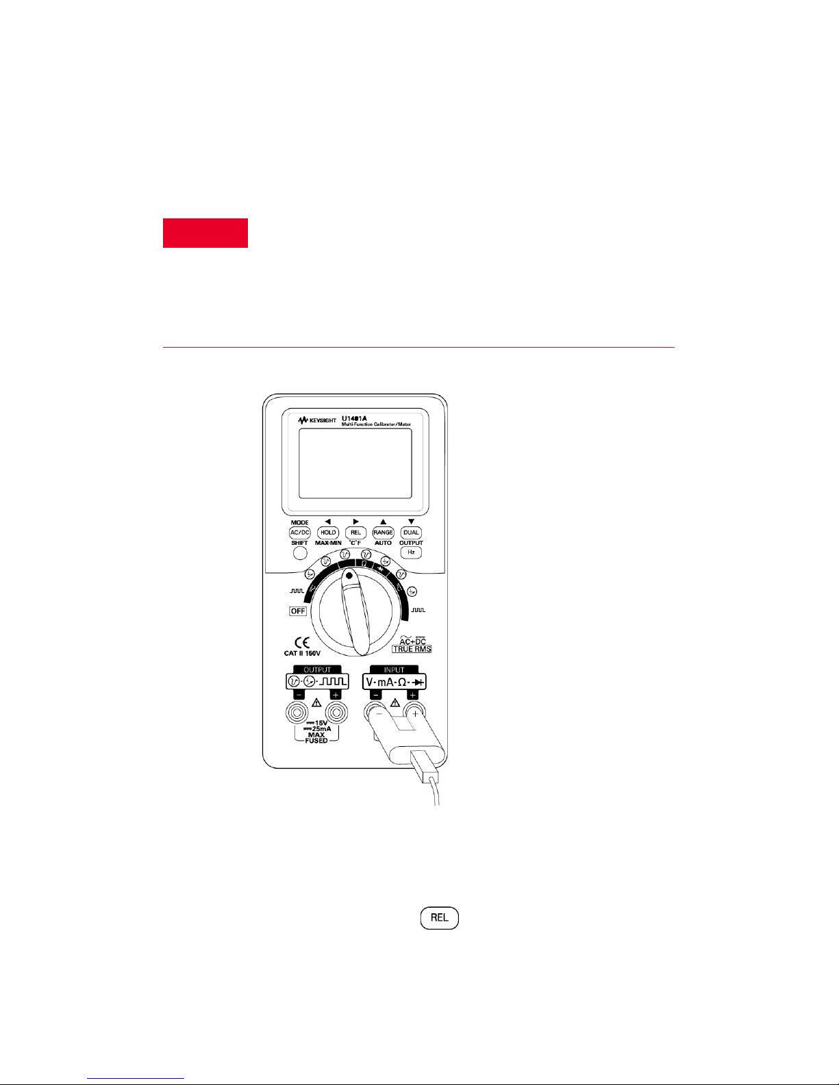
Performing Temperature Measurements
1 Set the slide switch to the M position to
disable the output.
2 Set the rotary switch to mV.
3 Press and hold for more than 1 second.
WARNING
– Before measuring the temperature of a circuit or
device, disconnect its power.
– The bead type thermocouple probe is suitable for
measuring temperature from –40 °C to 204 °C in
PTFE compatible environments. The probes may
emit toxic gas above this temperature range.
Page 19
Keysight U1401B Quick Start Guide 19
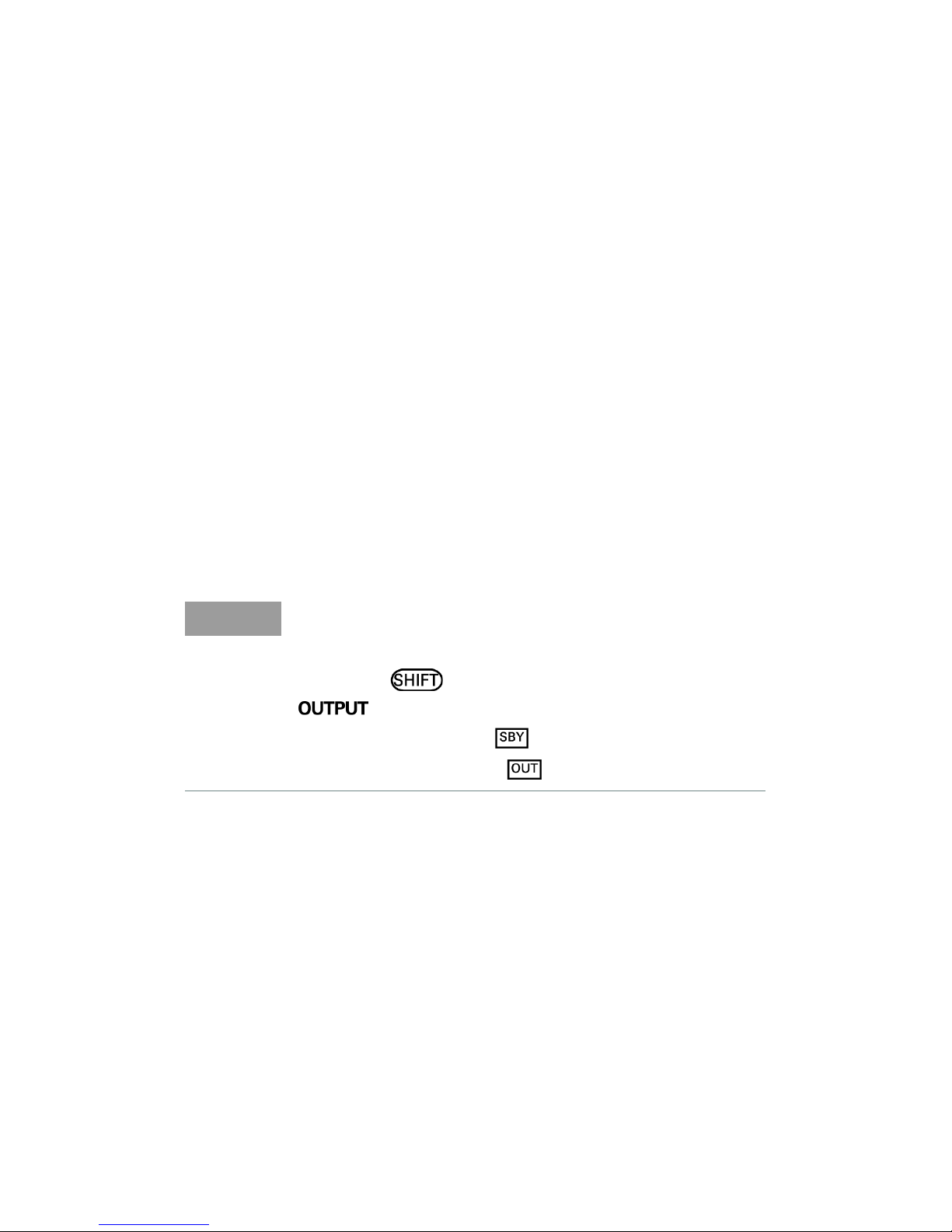
4 Plug the thermocouple probe (with adapter)
into the INPUT terminals.
5 Touch the surface to be measured with the
thermocouple probe and read the display.
Best practices:
– Do not bend the thermocouple leads at sharp
angles. Repeated bending may break the
leads.
– Do not immerse the thermocouple probe in
any liquid.
– Clean the surface to be measured and make
sure that the probe is securely touching the
surface.
NOTE
The U1401A can generate and measure signals
simultaneously.
While the mode is enabled, pressing
disables the U1401A output by placing it
in the standby mode ( ). Pressing OUTPUT again
toggles the output on ( ).
Page 20
20 Keysight U1401B Quick Start Guide
Frequency and Frequency Counter
Measurements
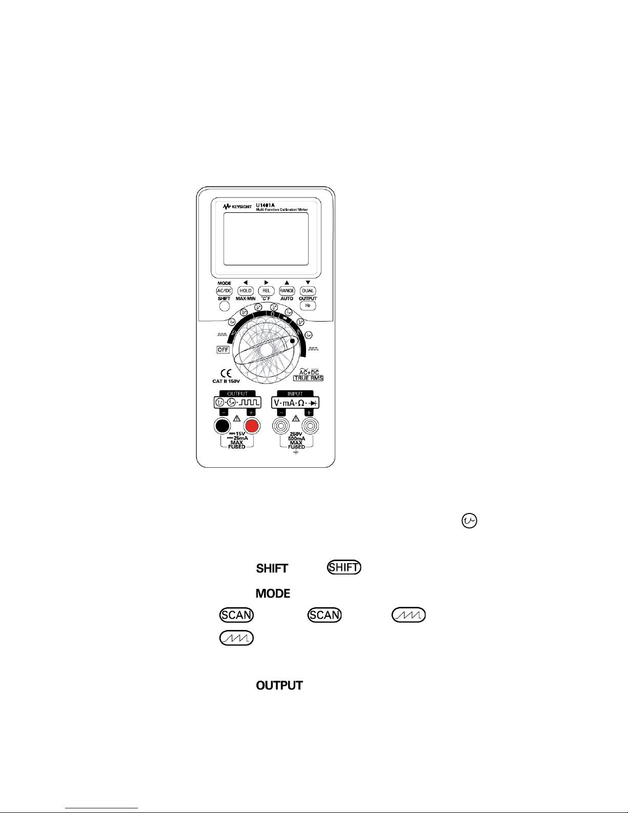
Constant voltage output
1 Set the rotary switch to any one of the
positions.
2 Press . The annunciator appears.
3 Press to cycle through ±1.5 V, ±15 V,
±1.5 V, ±15 V, ±1.5 V, and
±15 V output modes.
4 Select ±1.5 V or ±15 V.
5 Press to output the signal.
Page 21
Keysight U1401B Quick Start Guide 21
Constant current output
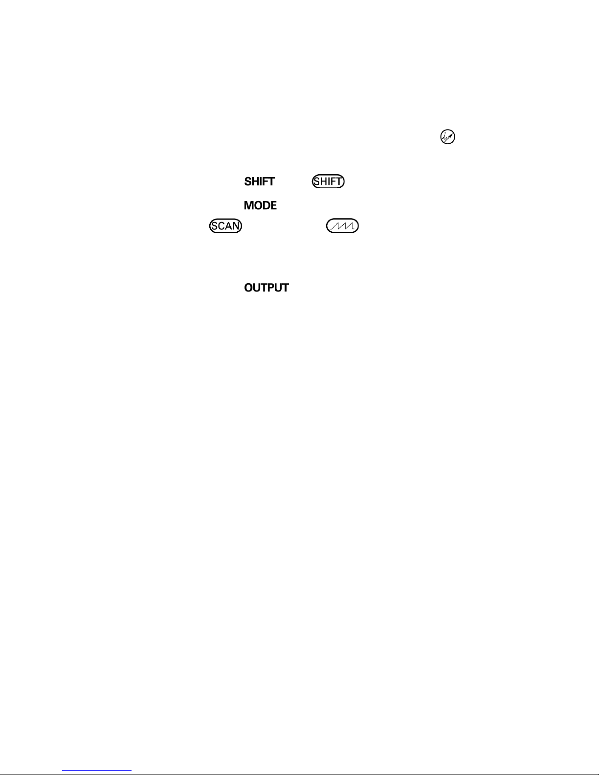
1 Set the rotary switch to any one of the
positions.
2 Press . The annunciator appears.
3 Press to cycle through ±25 mA,
±25 mA, and ±25 mA output
modes.
4 Select ±25 mA.
5 Press to output the signal.
Autoscan and autoramp outputs
The voltage and current outputs can also be
generated in predefined steps or ramp. Refer to
the User's and Service Guide for the detailed
procedures.
Page 22
22 Keysight U1401B Quick Start Guide
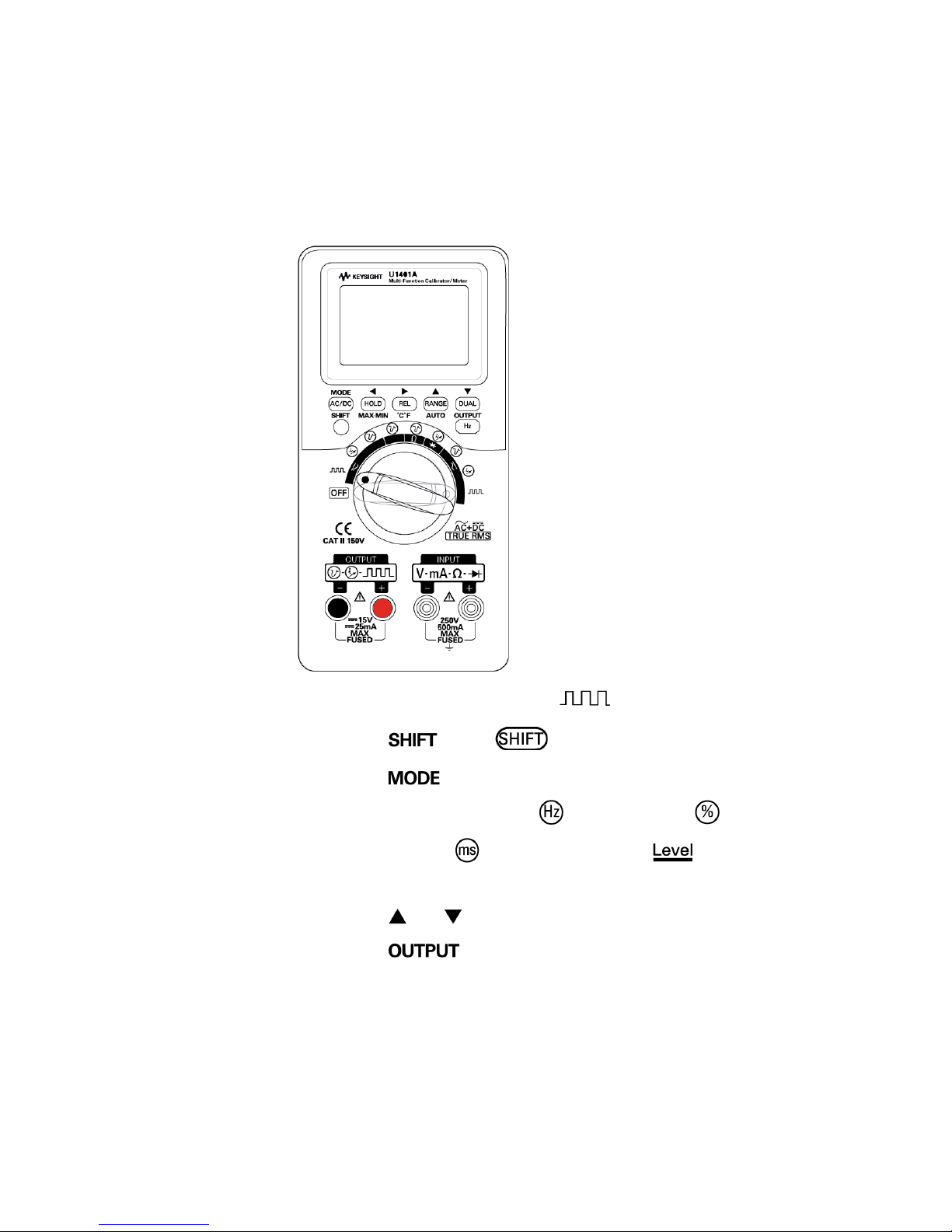
Square Wave Output
1 Set the rotary switch to .
2 Press . The annunciator appears.
3 Press to cycle through the adjustment
modes for frequency ( ), duty cycle ( ),
pulse width ( ), and amplitude ( ).
Select a parameter to adjust.
4 Press or to adjust the parameter value.
5 Press to output the square wave
signal.
Page 23
Keysight U1401B Quick Start Guide 23
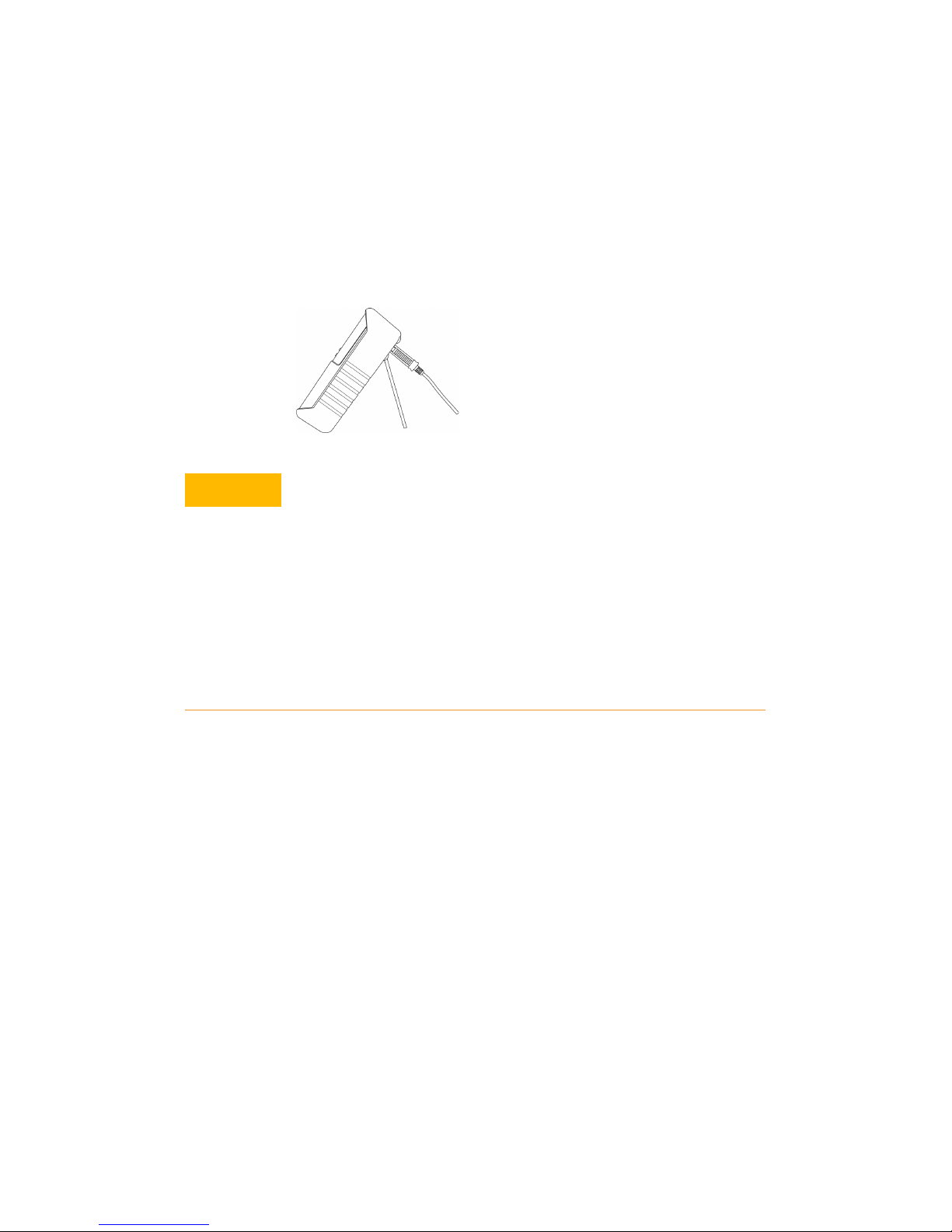
Tilt Stand
The instrument can be raised to a standing
position by means of a tilt stand.
CAUTION
Degradation of some product specifications can
occur in the presence of ambient electromagnetic
(EM) fields and noise that are coupled to the
powerline or I/O cables of the instrument. The
instrument will self-recover and operate to all
specifications when the source of ambient EM field
and noise are removed or when the instrument is
protected from the ambient EM field or when the
instrument cabling is shielded from the ambient EM
noise.
Page 24

24 Keysight U1401B Quick Start Guide
THIS PAGE HAS BEEN INTENTIONALLY LEFT BLANK.
Page 25

This information is subject to change
without notice. Always refer to the
Keysight website for the latest revision.
© Keysight Technologies 2006-2017
Edition 5, June 1, 2017
Printed in Malaysia
*U1401-90047*
U1401-90047
www.keysight.com
 Loading...