

Page 1

Keysight U1251B and U1252B
Handheld Digital Multimeter
Quick Start Guide
Page 2

Page 3
Keysight U1251B and
NOTE
WARNING
U1252B Handheld Digital
Multimeter
Quick Start Guide
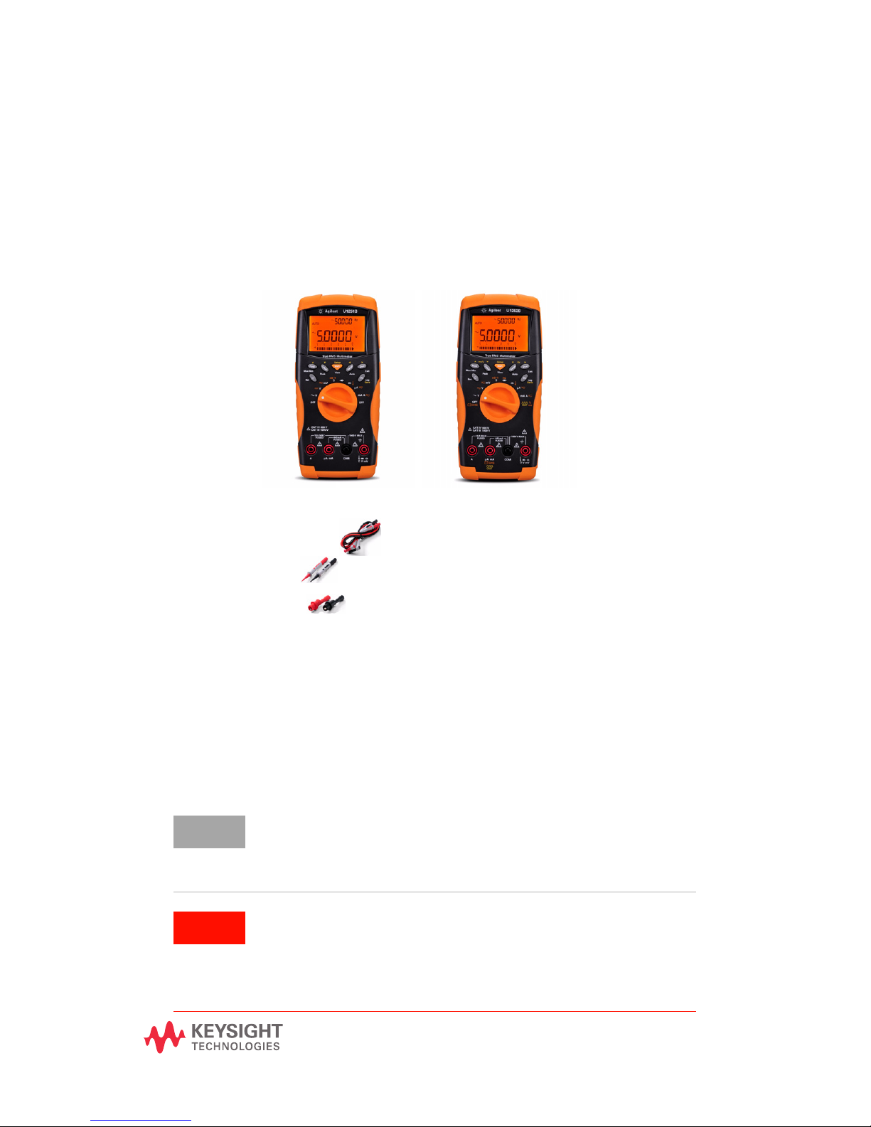
The following items are included with your multimeter:
✔ Silicone test leads
✔ 4 mm probes
✔ Alligator clips
✔ Printed Quick Start Guide
✔ Rechargeable 8.4 V battery (for
U1252B only)
✔ Power cord and AC adapter (for
U1252B only)
✔ Certificate of Calibration
✔ 9 V alkaline battery (for U1251B
only)
If anything is missing or damaged, please contact the nearest Keysight
Sales Office.
Your multimeter is capable of remote data logging. To use this feature,
you will need an IR-USB cable (U1173A, purchased separately) and the
Keysight GUI Data Logger Software (downloadable from
www.keysight.com/find/hhTechLib).
Ensure the terminal connections are correct for that
particular measurement selection before starting any
measurement. To avoid damage to the device, do not
exceed the input limit.
Page 4
Charging the Battery
NOTE
CAUTIONCAUTION
Use the specified accessory, the 24 V DC
adaptor to charge the battery.
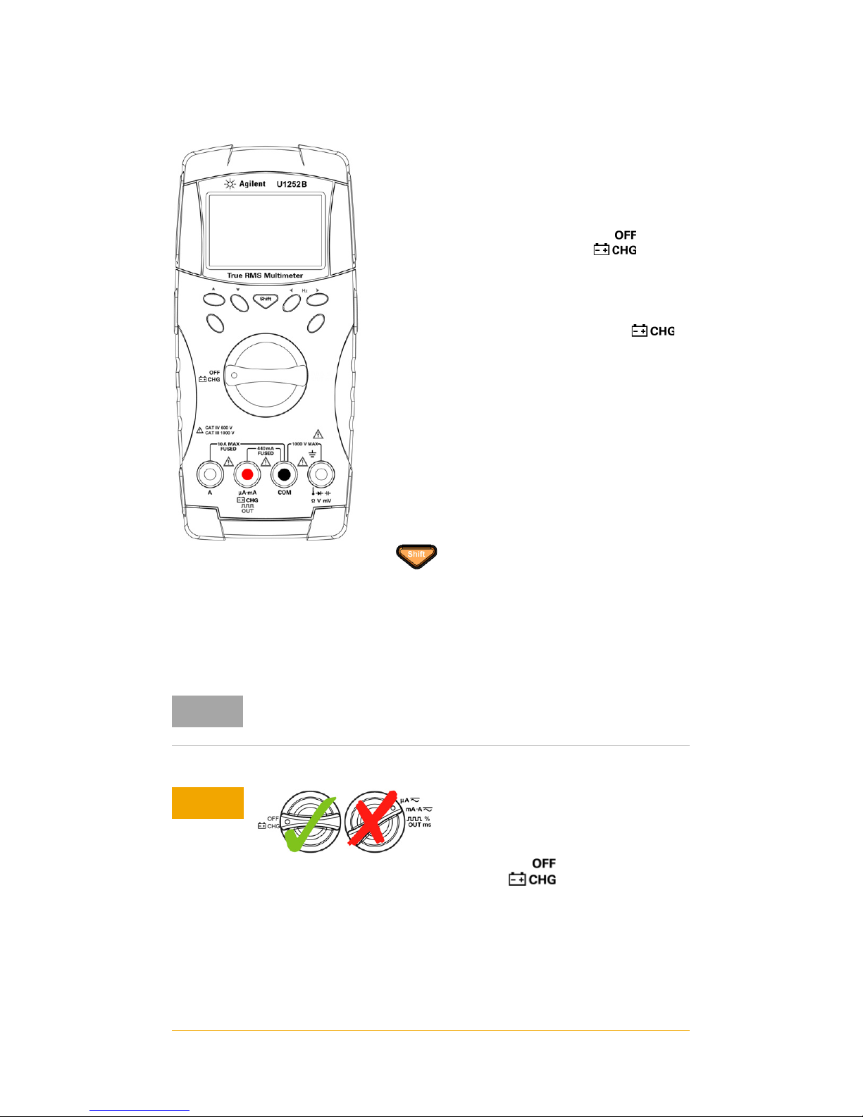
1 Remove and disconnect the test leads from
the meter.
2 Turn the rotary switch to the
position. Connect the power cord to the DC
adapter.
3 Plug the Red (+)/ Black (–) banana
terminals of the DC adapter to the
and the COM terminals respectively. The
DC adaptor can be replaced with a DC
power supply in order to set the 24 V DC
output and the over current limitation to a
value more than 0.5 A. Ensure that the
polarity of the connection is correct.
4 The primary display indicates “bAt” and
the ‘SbY” flashes on the secondary display
and a short tone sounds to remind you
whether to charge the battery or not. Press
to start charging the battery, or the
meter will automatically start the self-test
after the 24 V supply is applied. We
recommend not to charge the battery if its
capacity is over 90%.
For the battery charger, the mains supply voltage should not
fluctuate by plus or minus 10%.
• Do not rotate the rotary switch from position when
charging the battery.
• Perform battery charging only with 7.2 V or 8.4 V NiMH
rechargeable battery, 9 V size.
• Disconnect test leads from all the terminals when charging
the battery.
• Ensure proper insertion of battery in the multimeter, and follow
the correct polarity.
U1251B and U1252B Quick Start Guide
Page 5
CAUTIONCAUTION
• Upon initial use (or after a prolonged storage period), the
rechargeable battery may require three to four charge/discharge
cycles before achieving maximum capacity. To discharge, simply
run the multimeter under the rechargeable battery's power until
it shuts down or the low battery warning appears.
• The multimeter may indicate that charging is complete after ten
minutes when charging a new rechargeable battery. This is a
normal phenomenon with rechargeable batteries. Remove the
rechargeable battery from the device, reinsert it, and repeat the
charging procedure.
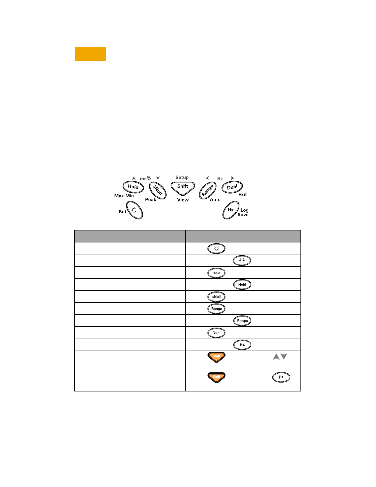
Functions and Features
Action Steps
Turns ON backlight Press .
Checks battery capacity Press and hold for >1 s.
Freezes the measured value Press .
Starts MIN/MAX/AVG recording Press and hold for >1 s.
Offsets the measured value Press .
Changes the measuring range Press .
Turns on auto range Press and hold for > 1 s.
Turns on dual display Press .
Starts manual data logging Press and hold for > 1 s.
Views the logged data Press for > 1 s, press
to scroll through the logged data.
Clears the logged data Press for > 1 s, press
for >1 s.
U1251B and U1252B Quick Start Guide
Page 6
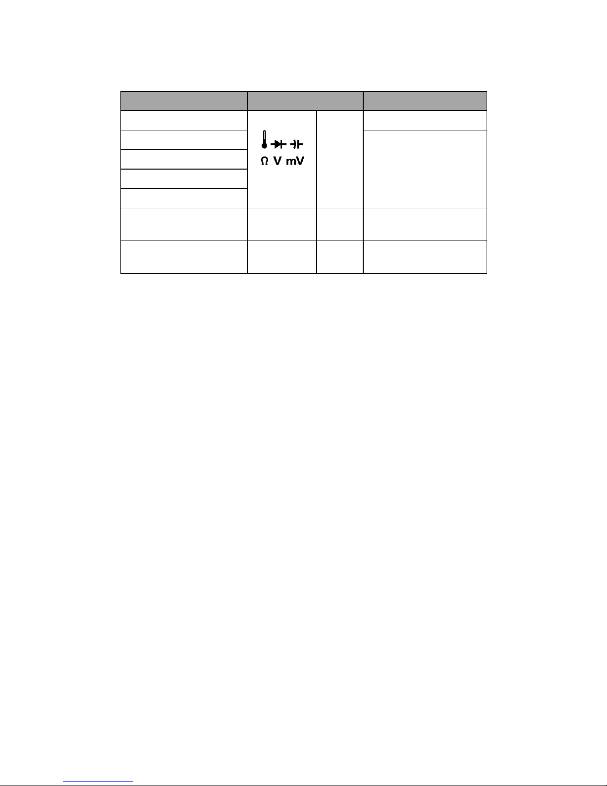
Input Terminals and Overload Protection
Measurement Functions Input Terminal Overload Protection
Voltage COM 1000 V R.M.S
Diode 1000 V R.M.S
Resistance
Capacitance
Temperature
Current (μA and mA) µA.mA COM 440 mA/1000 V 30
Current (A) A COM 11 A/1000 V 30
< 0.3 A short circuit
current
kA/fast-acting fuse
kA/fast-acting fuse
U1251B and U1252B Quick Start Guide
Page 7
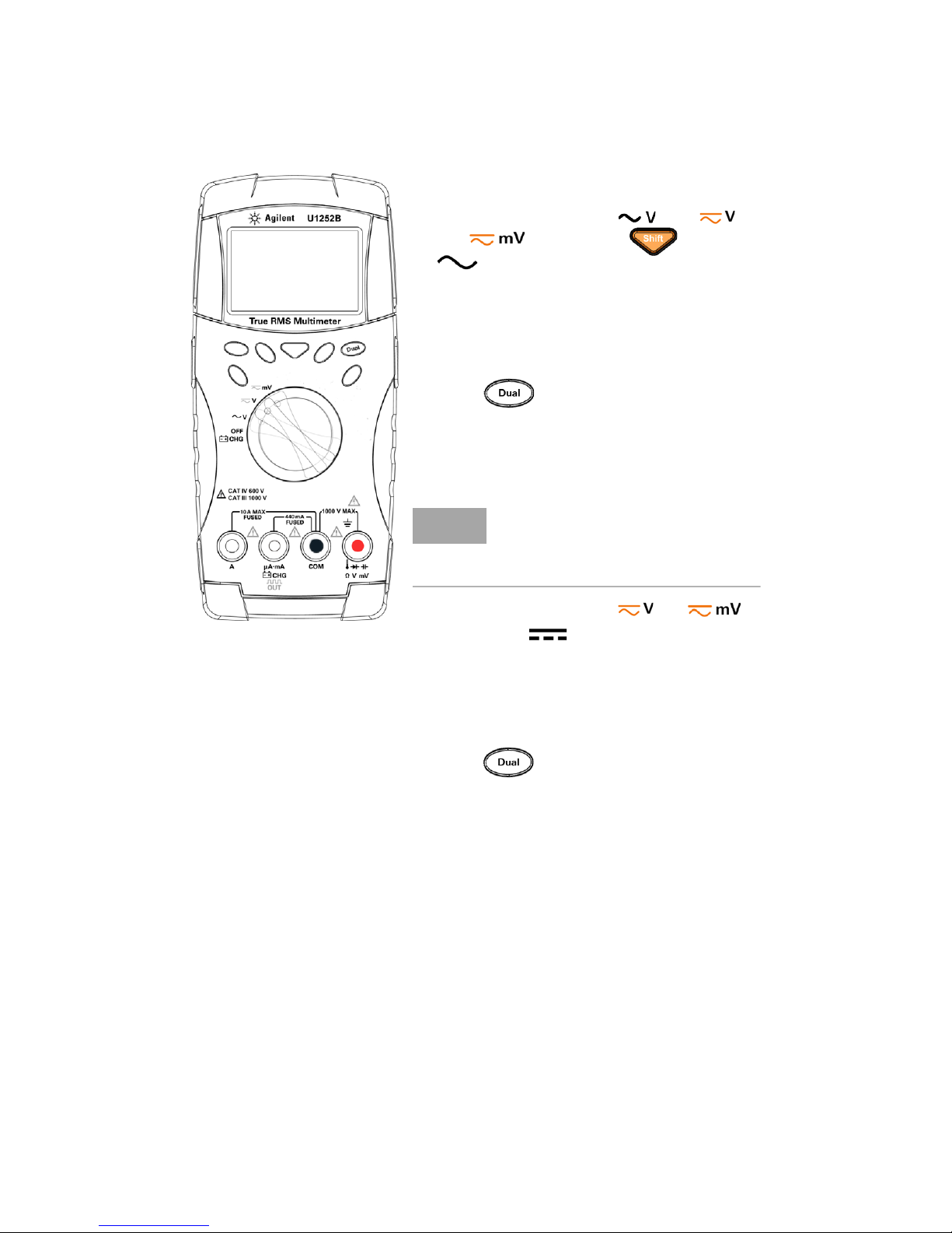
Performing Voltage Measurements
Measuring AC voltage
1 Set the rotary switch to . For
and mode, press to ensure
is shown on the display.
2 Connect the red and black test leads to
input terminals V. mV (red) and COM
(black) respectively.
3 Probe the test points and read the display.
4 Press to display dual
measurements. Parameter can be switched
consecutively.
Measuring DC voltage
1 Set the rotary switch to or .
Ensure that is shown on the display.
2 Connect the red and black test leads to
input terminals V. mV (red) and COM
(black) respectively.
3 Probe the test points and read the display.
4 Press to display dual
measurements. Parameters can be
switched consecutively.
NOTE
For measuring DC voltage from a
mixed signal in DC measurement
mode, ensure that the Filter is
enabled
U1251B and U1252B Quick Start Guide
Page 8
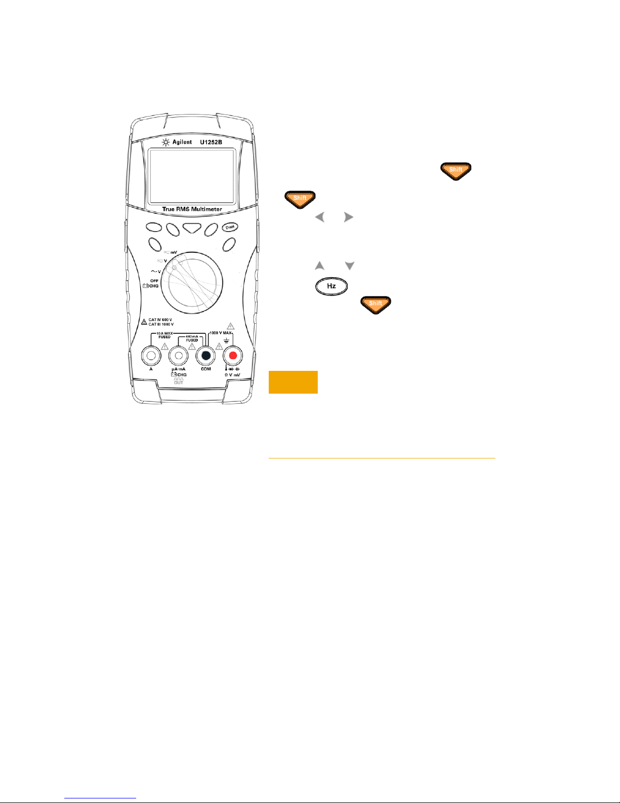
Using the Filter
1 To enter the Setup mode, switch off the
meter, then turn the rotary knob to any
non-OFF position while holding
until you hear a beep. You may release
once you hear the beep.
2 Press or to scroll through the menu
items until FiLtE is shown in the secondary
display.
3 Press or to enable the Filter.
4 Press to save your changes.
5 Press and hold until the meter
restarts and returns to its normal operating
mode.
CAUTIONCAUTION
To avoid possible electric shock or personal injury, enable the Filter to verify
the presence of hazardous DC voltages.
Displayed DC voltages can be influenced
by high frequency AC components and
must be filtered to assure an accurate
reading.
U1251B and U1252B Quick Start Guide
Page 9
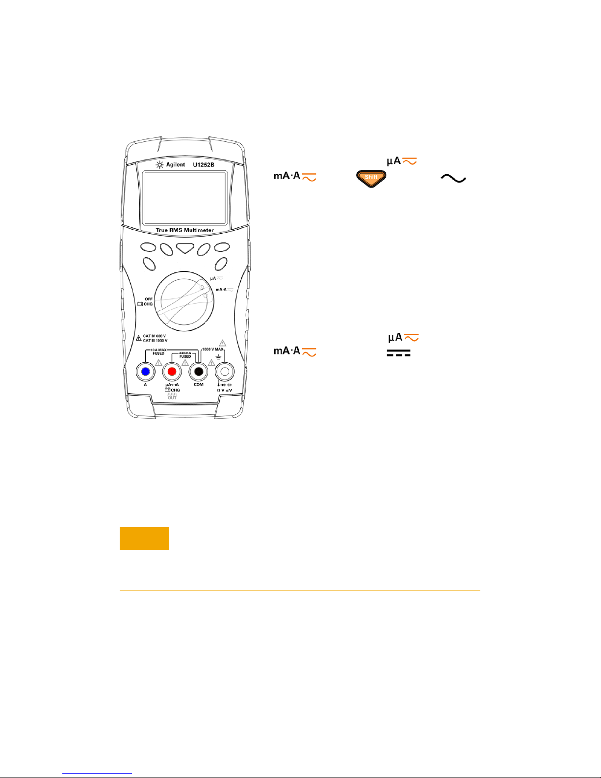
Performing Current Measurements
CAUTIONCAUTION
Measuring AC current
1 Set the rotary switch to or
. Press to ensure
is shown on the display.
2 Connect the red and black test leads to
input terminals µA.mA (red) and COM
(black) or A (blue) and COM (black)
respectively.
3 Probe the test points in series with the
circuit and read the display.
Measuring DC current
1 Set the rotary switch to or
. Ensure that is shown on
the display.
2 Connect the red and black test leads to
input terminals µA.mA (red) and COM
(black) or A (blue) and COM (black)
respectively.
3 Probe the test points in series with the
circuit and read the display.
• If the current is ≤ 440 mA, connect the red and black test
leads to input terminals µA.mA (red) and COM (black).
• If the current is > 440 mA, connect the red and black test
leads to input terminals A (red) and COM (black).
U1251B and U1252B Quick Start Guide
Page 10
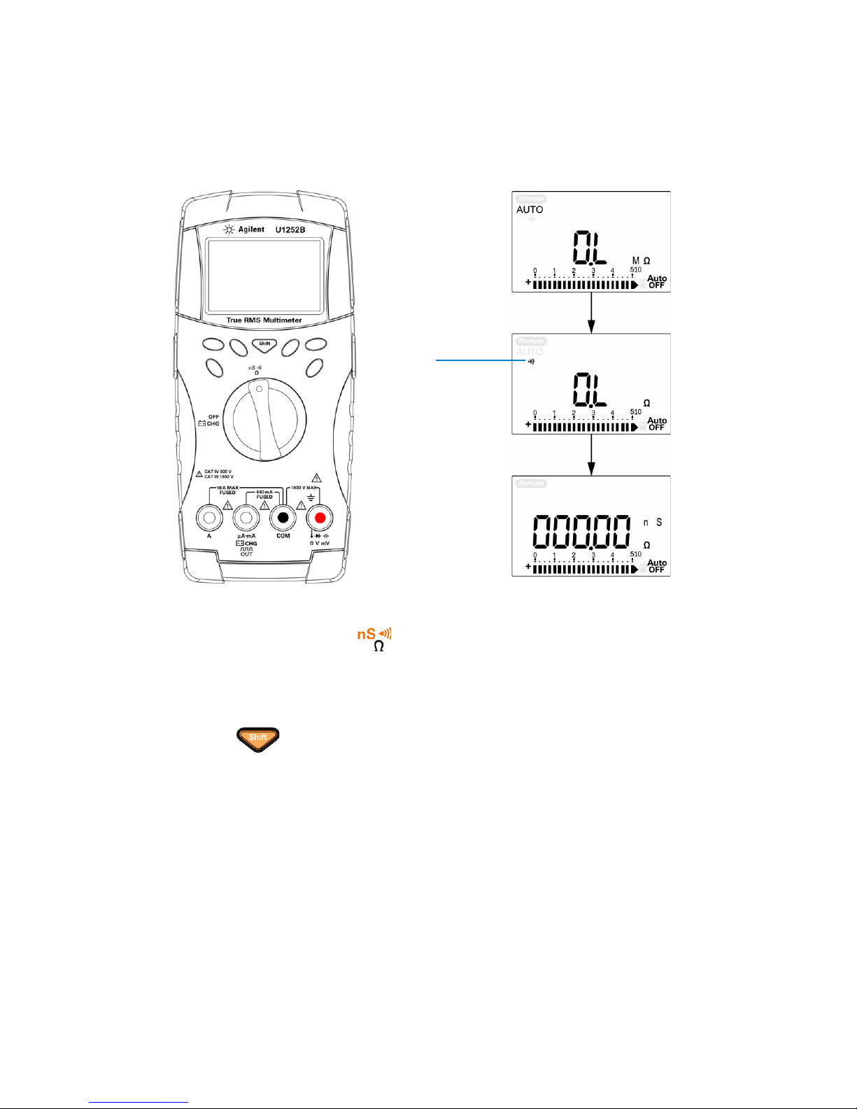
Performing Resistance, Conductance, and
1 Set the rotary switch to .
2 Connect the red and black test leads to input terminals
Ω (red) and COM (black) respectively.
3 Probe the test points (by shunting the resistor) and read the display.
4 Press to scroll through audible continuity, conductance, and
resistance tests as shown.
Audible
continuity
Continuity Measurements
U1251B and U1252B Quick Start Guide
Page 11
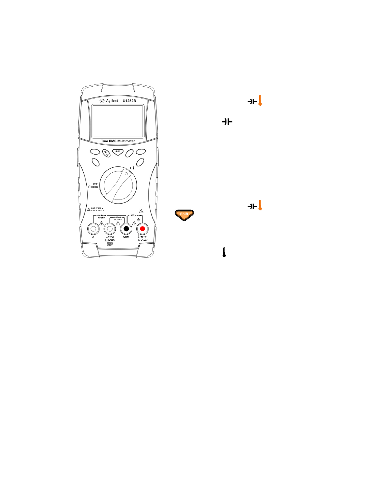
Performing Capacitance and Temperature
Capacitance
1 Set the rotary switch to .
2 Connect the red and black test leads to
input terminals (red) and COM
(black) respectively.
3 Connect the red test lead to the positive
terminal of the capacitor, and the black test
lead to the negative terminal.
4 Read the display.
Temperature
1 Set the rotary switch to . Press
to select temperature
measurement.
2 Plug the thermocouple adapter (with the
thermocouple probe connected to it) into
input terminals (red) and COM (black).
3 Touch the measurement surface with
the thermocouple probe.
4 Read the display.
Measurements
U1251B and U1252B Quick Start Guide
Page 12
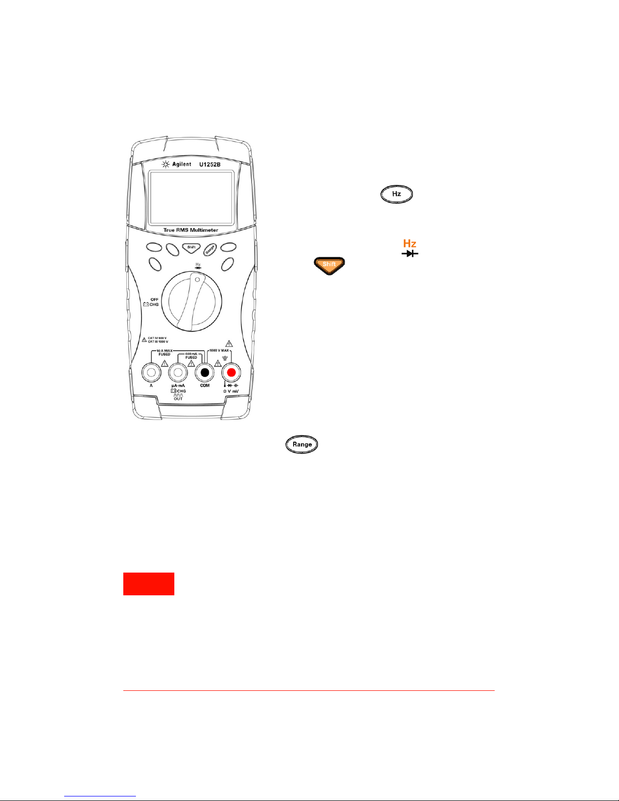
Frequency and Frequency Counter
WARNING
Frequency Measurement
During AC/DC voltage or AC/DC current
measurements, you can measure the signal
frequency by pressing at any time.
Frequency Counter Measurement
1 Set the rotary switch to .
2 Press to select the frequency
counter (Hz) function. “—1—” on the
secondary display means the input signal
frequency is divided by 1. This
accommodates for higher frequency range
of up to 985 kHz.
3 Connect the red and black test leads to
input terminals V (red) and COM (black)
respectively.
4 Probe the test points and read the display.
5 If the reading is unstable or zero, press
to select division of input signal
frequency by 100. This accommodates a
higher frequency range of up to 20 MHz.
6 The signal is out of range if the reading is
still unstable after step 5.
Measurements
• Use the frequency counter for low voltage applications.
Never use the frequency counter on AC power line
systems.
• For input more than 30 Vpp, you are required to use
frequency measurement mode available under the
current or voltage measurement instead of frequency
counter.
U1251B and U1252B Quick Start Guide
Page 13
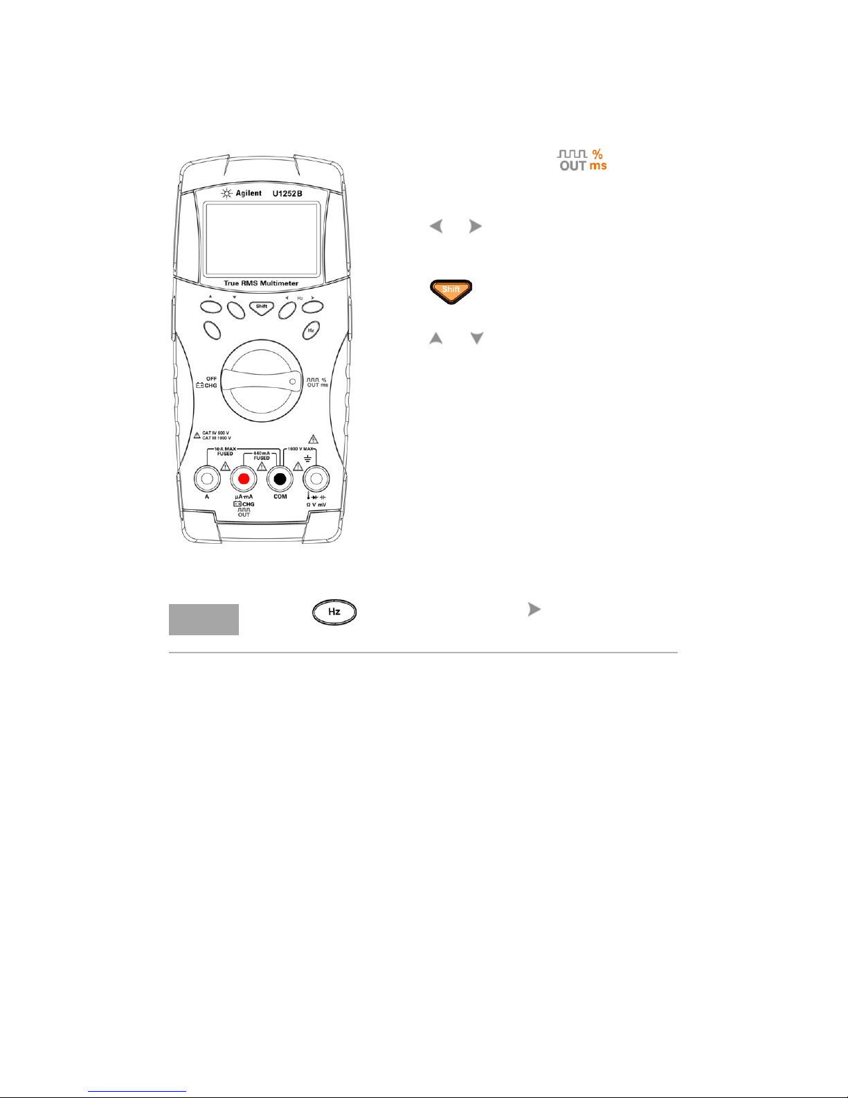
Square Wave Output (for U1252B only)
NOTE
1 Turn the rotary switch to . Default
display setting is 600 Hz on secondary display
and 50% duty cycle on primary display.
2 Press or to scroll through the
available frequencies (there are 28
frequencies to choose from).
3 Press to select duty cycle (ms) on
the primary display.
4 Press or to adjust the duty cycle.
Duty cycle can be set for 256 steps and
each step is 0.390625%. The display only
indicates the best resolution with 0.001%.
Pressing is the same as pressing .
U1251B and U1252B Quick Start Guide
Page 14
Safety Notices Safety Information
CAUTIONCAUTION
WARNING
CAT III
1000 V
CAT IV
600 V
A CAUTION notice denotes
a hazard. It calls attention
to an operating procedure,
practice, or the like that, if
not correctly performed or
adhered to, could result in
damage to the product or
loss of important data. Do
not proceed beyond a
CAUTION notice until the
indicated conditions are
fully understood and met.
A WARNING notice
denotes a hazard. It calls
attention to an operating
procedure, practice, or the
like that, if not correctly
performed or adhered to,
could result in personal
injury or death. Do not
proceed beyond a
WARNING notice until the
indicated conditions are
fully understood and met.
This meter is safety-certified in compliance
with EN/IEC 61010-1:2001, UL 61010-1
Second Edition and CAN/CSA 22.2 61010-1
Second Edition, CAT III 1000 V/CAT IV 600 V
Overvoltage Protection, Pollution Degree II.
Use with standard or compatible test
probes.
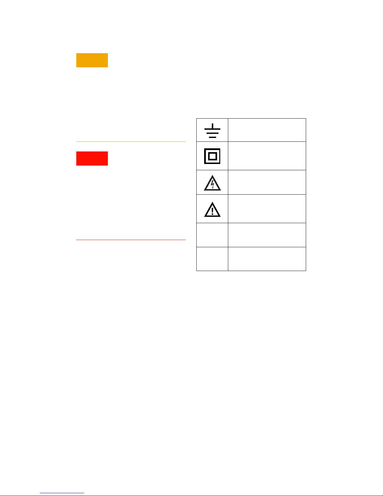
Safety Symbols
Earth (ground) terminal
Equipment protected
throughout by double
insulation or reinforced
insulation
Caution, risk of electric
shock
Caution, risk of danger (refer
to the instrument manual for
specific Warning or Caution
information)
Category III 1000 V
overvoltage protection
Category IV 600 V
overvoltage protection
For further safety information details, refer to the
Keysight U1251B and U1252B Handheld Digital Multimeter User’s Guide.
Page 15

This information is subject to change without notice.
© Keysight Technologies 2009 - 2014
Edition 6, August 2014
*U1251-90046*
U1251-90046
www.keysight.com
 Loading...