

Page 1

Keysight TS-5020 Automotive Electronics Functional Test System
Wiring Guide And
Hardware Reference
Page 2

Page 3
Page 4

Notices
© Keysight Technologies 2006 - 2015
No part of this manual may be reproduced
in any form or by any means (including
electronic storage and retrieval or translation into a foreign language) without prior
agreement and written consent from Keysight Technologies as governed by United
States and international copyright laws.
Manual Part Number
E2240-90001
Edition
Edition 4, March 2015
Printed in Malaysia
Keysight Technologies Microwave Products
(Malaysia) Sdn. Bhd.
Bayan Lepas Free Industrial Zone
11900 Penang, Malaysia
Technical Assistance
You can find information about technical
and professional services, product support,
and equipment repair and service on the
Web:
http://www.keysight.com/contacts/English/noscript.html
Double-click the link to Tes t & Me a s u r e -
ment. Select your country from the
drop-down menus. The Web page that
appears next has contact information specific for your country.
If you do not have access to the Internet,
call one of the numbers in Ta b l e 1.
Tab l e 1 Keysight Call Centers
United States
and Canada:
Europe: (41 22) 780 8111
Japan: Measurement
Latin America: 305 269 7548
Asia-Pacific: (85 22) 599 7777
United States
and Canada:
Te s t a n d
Measurement Call
Center
(800) 452 4844
(toll-free in US)
Assistance Center
(81) 0426 56 7832
Te s t a n d
Measurement Call
Center
(800) 452 4844
(toll-free in US)
Page 5

Contents
1 Legal Information
Legal Information 1-2
Warranty 1-2
Technology Licenses 1-2
Restricted Rights Legend 1-2
Service And Support 1-3
Keysight On The Web 1-3
Keysight By Phone 1-3
2 Safety and Regulatory Information
Safety Information 2-2
Safety Summary 2-2
Safety Notice 2-2
General 2-2
Environmental Conditions 2-3
Before Applying Power 2-3
Ground The System 2-4
Fuses 2-4
Operator Safety Information 2-4
Safety Symbols and Regulatory Markings 2-5
Electrostatic Discharge (ESD) Precautions 2-7
End of Life: Waste Electrical and Electronic Equipment (WEEE) Directive 2002/96/EC 2-8
3 System Overview
System Intended Use 3-2
Instructions For Use 3-2
Test System Specifications and Capabilities 3-3
Test Capabilities – Measurement Sample Methods 3-4
System Capability DC Accuracy Sample 3-4
Test System Interface Description 3-6
Test System Interface Connectors 3-6
Rack Layout with Express Connect Test System Interface 3-28
Rack Layout with L2000 (TITAN) Test System Interface 3-29
System Block Diagrams with Express Connect Test System Interface 3-30
System Block Diagrams with L2000 (TITAN) Test System Interface 3-31
The Keysight 34980A Multifunction Switch/Measure Unit 3-32
Slot Allocation of the 34980A 3-32
TS-5020 Automotive Electronics Functional Test System Wiring Guide and Hardware Reference iii
Page 6

PC Cards 3-36
Keysight 53131 Universal Counter 3-36
Keysight 53220 Universal Counter 3-36
Keysight 33220 Function/Arbitrary Waveform Generator 3-37
Power Supplies 3-37
Keysight N6700 MPS 3-37
Channel Names 3-38
4 System Interconnects
System Interconnects for Express Connect Interface 4-2
Connector Keying 4-2
Connectors and Tools 4-3
Connecting Wiring to Test Connectors TC1- TC8 4-3
Crimping Wires to Contacts 4-4
Inserting Contacts and Assembling the Connectors 4-5
Connecting To The Test System Interface 4-6
ESD Protection Measures 4-7
Test Connector Signal Definitions 4-9
General TC Pins Assignment 4-13
Express Connect PCA Connector Definition and Pin Access 4-15
High-Power Connector 4-21
System Interconnect for Mac Panel Interface 4-23
L2000 (TITAN) Connectors and Tools 4-23
5 Test System Interface Cables
U8970-61702 Dual Banana Metric Cable for GPIB/LXI DMM 5-3
U8970-61701 Cable BNC Coax to 3x1 (Non-Isolated) 5-3
U8970-61700 Cable Isolated Instrument BNC 5-3
Cables For Express Connect Interface 5-4
E6170-61623 Twinax DMM To Inst Matrix Cable 5-4
E6170-61626 DIO And Utility Power Supply To ICA Cable 5-4
E6170-61627 DMM Trig 34980 To ICA 5-6
E6170-61628 DAC 34951 To ICA Cable 5-6
E6170-61629 GP Relay 34938A And Power Supply To ICA Cable 5-8
E6170-61620 General Purpose 96-96 DINC Cable 5-10
E6170-61621 48 Channel Load Card Express Connect Cable 5-10
E6170-61630 CAN PCI To ICA Cable 5-11
E6170-61605 Cable for 8-CH/16-CH/24-CH Load Card to Express Connect 5-12
E6230-61603 Cable for 8-CH Heavy Duty Load Card to Express Connect 5-13
Cables For L2000 (TITAN) Interface 5-14
iv TS-5020 Automotive Electronics Functional Test System Wiring Guide and Hardware Reference
Page 7

E6218-61601 Cable, One Matrix (34933A) to L2000 (TITAN) 5-14
E6218-61614 CABLE, E6175A TO L2000 (TITAN) 5-15
E6218-61615 CABLE, E6176A TO L2000 (TITAN) 5-15
E6218-61620 CABLE, N9379A TO L2000 (TITAN) 5-16
E6218-61621 CABLE, 34951-DAC TO L2000 (TITAN) 5-17
E6218-61622 CABLE, 34980-DMM (TRIG) TO L2000 (TITAN) 5-17
E6218-61624 CABLE, E6178B TO L2000 (TITAN) 5-18
E6218-61625 CABLE, ONE U7177A TO L2000 (TITAN) 5-19
E6218-61627 CABLE, DIO TO L2000 (TITAN) 5-20
E6218-61628 CABLE, PS TO L2000 (TITAN) (MED CURRENT) 5-20
E6218-61629 CABLE, 34938 TO L2000 (TITAN) 5-21
E6218-61630 CABLE, CAN TO L2000 (TITAN) 5-21
E2240-61621 Cable, 34934A to ICA (TITAN) 5-22
E2240-61622 Cable, 34939A to ICA (TITAN) 5-23
E2240-61623 Cable, Electronic Load to ICA (TITAN) 5-24
E2240-61626 Cable, System Resources E6198B and PCI DIO 1750 5-25
E6218-61619 Cable, System Resources To L2000 (TITAN) 5-26
E6218-61626 CABLE, Dual 24-CH Load Card To L2000 (TITAN) 5-27
6 Replaceable And Spare Parts
Keysight E2230A Replaceable Parts 6-2
Keysight E2240A Recommended Spare Parts for Express Connect 6-4
Keysight E2240A Recommended Spare Parts for L2000 (TITAN) 6-5
TS-5020 Automotive Electronics Functional Test System Wiring Guide and Hardware Reference v
Page 8

THIS PAGE IS INTENTIONALLY LEFT BLANK
vi TS-5020 Automotive Electronics Functional Test System Wiring Guide and Hardware Reference
Page 9

List of Figures
1 Legal Information
2 Safety and Regulatory Information
3 System Overview
Figure 3-1. Express Connect Test System Interface TC1 Through TC4 3-7
Figure 3-2. Express Connect Test system Interface TC1 Through TC8 3-8
Figure 3-3. Macpanel L2000 (TITAN) Test System Interface 3-10
Figure 3-4. Typical TS-5020 System Rack with Express Connect Layout 3-28
Figure 3-5. Typical TS-5020 System with L2000 (TITAN) test interface 3-29
Figure 3-6. TS-5020 Simplified System with Express Connect Block Diagram 3-30
Figure 3-7. TS-5020 Simplified System with L2000 (TITAN) Block Diagram 3-31
Figure 3-8. Rear View Of 34980A Multifunction Switch / Measure Unit 3-32
Figure 3-9. Cut-out View of Slot 4 with Terminal Card To Create Instument/Pin
Figure 3-10. Multiple 34933A configured as Instrumentation and Pin Matrix 3-34
Figure 3-11. Multiple 34934A configured as Instrumentation and Pin Matrix 3-35
Matrix 3-33
4 System Interconnects
Figure 4-1. TC1-TC4 Connector Keying 4-2
Figure 4-2. TC1-TC8 Connector Key Configuration 4-2
Figure 4-3. Crimping Wires to Contacts 4-4
Figure 4-4. Assembling TC1 to TC4 4-5
Figure 4-5. Connecting To The Test System Interface 4-6
Figure 4-6. Adding A Grounding Strap To Reduce ESD 4-7
Figure 4-7. Wrist Strap ESD Connector 4-8
Figure 4-8. Removing A Test Connector Contact 4-8
Figure 4-9. TC1 Pinouts 4-11
Figure 4-10. TC2 Pinouts 4-12
Figure 4-11. TCn Pin Assignments 4-13
Figure 4-12. TCn+1 Pin Assignments 4-14
Figure 4-13. PCA Layout For Full Profile Express Connect (For TC1-TC8 Use) 4-15
Figure 4-14. View of Full Profile Express Connect PC Assembly (2 of 4 possible PC
Assembly shown) 4-16
Figure 4-15. PCA Layout For Low Profile Express Connect (For TC1-TC4 Use) 4-17
Figure 4-16. TS-5020 System Connector (J6 or J60) TC1 and TC2 Assignments 4-18
Figure 4-17. TS-5020 System Connector (J6 or J60) TCn Assignments 4-19
Figure 4-18. TS-5020 Configuration Connector (J7 or J40) 4-20
Figure 4-20. Recommended System Grounding 4-22
TS-5020 Automotive Electronics Functional Test System Wiring Guide and Hardware Reference vii
Page 10

5 Test System Interface Cables
Figure 5-1. U8970-61702 (Dual Banana Metric Cable) 5-3
Figure 5-2. U8970-61701 (Cable BNC Coax to 3x1) 5-3
Figure 5-3. U8970-61700 (Cable Isolated Instrument BNC) 5-3
Figure 5-4. E6170-61623 Twinax DMM To Inst Matrix Cable 5-4
Figure 5-5. E6170-61626 DIO And Utility Power Supply To ICA Cable 5-4
Figure 5-6. E6170-61627 DMM Trig 34980 To ICA 5-6
Figure 5-7. E6170-61628 DAC 34951 To ICA Cable 5-6
Figure 5-8. E6170-61629 Cable 5-8
Figure 5-9. E6170-61620 General Purpose 96-96 DINC Cable 5-10
Figure 5-10. E6170-61621 48 Channel Load Card Express Connect Cable 5-10
Figure 5-11. E6170-61630 CAN PCI To ICA Cable 5-11
Figure 5-12. E6170-61605 Cable for Load card to Express Connect. This cable can be used
for E6175A, N9377A, E6176A, E6177A, U7177A and N9378A. 5-12
Figure 5-13. Cable for E6178B 8-CH Heavy duty Load card to Express Connect 5-13
Figure 5-14. E6218-61601 Cable, One Matrix (34933A) to L2000 (TITAN) 5-14
Figure 5-15. E6218-61614 CABLE, E6175A TO L2000 (TITAN) 5-15
Figure 5-16. E6218-61615 Cable, E6176A to L2000. This cable is used for E6176A and
N9377A 5-15
Figure 5-17. E6218-61620 CABLE, N9379A TO L2000 (TITAN) 5-16
Figure 5-18. E6218-61621 CABLE, 34951-DAC TO L2000 (TITAN) 5-17
Figure 5-19. E6218-61622 CABLE, 34980-DMM (TRIG) TO L2000 (TITAN) 5-17
Figure 5-20. E6218-61624 CABLE, E6178B TO L2000 (TITAN) 5-18
Figure 5-21. E6218-61625 Cable, One U7177A to L2000. This cable is used for E6177A,
U7177A and N9378A. 5-19
Figure 5-22. E6218-61627 CABLE, DIO TO L2000 (TITAN) 5-20
Figure 5-23. E6218-61628 CABLE, PS TO L2000 (TITAN) (MED CURRENT) 5-20
Figure 5-24. E6218-61629 CABLE, 34938 TO L2000 (TITAN) 5-21
Figure 5-25. E6218-61630 CABLE, CAN TO L2000 (TITAN) 5-21
Figure 5-26. E2240-61621 Cable, 34934A to ICA (TITAN). One cable requires two TITAN
receiver block. 5-22
Figure 5-27. E2240-61622 Cable, 34934A to ICA (TITAN) 5-23
Figure 5-28. E2240-61623 Cable, Electronic Load to ICA (TITAN). This cable has an in-line
50A fuse. 5-24
Figure 5-29. E2240-61626 Cable, System Resources E6198B and PCI DIO 1750. This cable
combines the system resources cable for E6198B with the cable for PCI DIO
1750. 5-25
Figure 5-30. E6218-61619 Cable, System Resources to L2000 (TITAN). This cable
combines the system resources cable for E6218A with the cable for PCI DIO
1750. 5-26
Figure 5-31. E6218-61626 Cable, Dual 24-CH Load Card to L2000 (TITAN). This cable
combines 2 24-CH load card cable to a single receiver block. 5-27
6 Replaceable And Spare Parts
viii TS-5020 Automotive Electronics Functional Test System Wiring Guide and Hardware Reference
Page 11

List of Tables
1 Legal Information
2 Safety and Regulatory Information
3 System Overview
Table 1-1. Keysight Call Centers and Regional Headquarters 1-3
Table 2-1. Environment Requirements 2-3
Table 2-2. Safety Symbols and Regulatory Markings 2-5
Table 2-3. Suggested Anti-Static Solutions for Site Planning 2-7
Table 3-1. Typical TS-5020 Instrumentation 3-3
Table 3-2. L2000 (TITAN) Slot 1 (System) 3-11
Table 3-3. L2000 (TITAN) Slot 2 (Instruments) 3-12
Table 3-4. L2000 (TITAN) Slot 3 (DAC) 3-13
Table 3-5. L2000 (TITAN) Slot 4 (RS232) 3-14
Table 3-6. L2000 (TITAN) Slot 6 (Pin Matrix 1st Card 34933A) 3-15
Table 3-7. L2000 (TITAN) Slot 7 to 9 (Matrix Card 34933A) 3-16
Table 3-8. L2000 (TITAN) Slot 6 (Pin Matrix 1st Card (34934A)) 3-17
Table 3-9. L2000 (TITAN) Slot 7 (Pin Matrix 1st Card (34934A)) 3-18
Table 3-10. L2000 (TITAN) Slot 8/21/23 (Pin Matrix Card (34934A)) 3-19
Table 3-11. L2000 (TITAN) Slot 9/22/24 (Pin Matrix Card (34934A)) 3-20
Table 3-12. L2000 (TITAN) Slot 12 to 15 (GP relay Card (34938A)) 3-21
Table 3-13. L2000 (TITAN) Slot 12 to 15 (GP relay Card (34939A)) 3-22
Table 3-14. L2000 (TITAN) Slot 11 to 20 (24-CH Load Card) 3-23
Table 3-15. L2000 (TITAN) Slot 13 to 20 (16-CH Load Card) 3-24
Table 3-16. L2000 (TITAN) Slot 13 to 20 (48-CH Load Card) 3-25
Table 3-17. L2000 (TITAN) Slot 13 to 20 (8-CH Load Card) 3-26
Table 3-18. L2000 (TITAN) Slot 16 & 18(Heavy Duty Load Card & Electronic Load) 3-27
Table 3-19. L2000 (TITAN) Slot 25 (RF) 3-27
4 System Interconnects
Table 4-1. TCx Signal Definitions 4-9
5 Test System Interface Cables
Table 5-1. E6170-61626 Cable Pinout Table 5-5
Table 5-2. E6170-61628 Cable Pinout Table 5-7
Table 5-3. E6170-61629 Cable Pinout Table 5-9
6 Replaceable And Spare Parts
TS-5020 Automotive Electronics Functional Test System Wiring Guide and Hardware Reference ix
Page 12

THIS PAGE IS INTENTIONALLY LEFT BLANK
x TS-5020 Automotive Electronics Functional Test System
Page 13

1 Legal Information
Warranty .... 1-2
Technology Licenses .... 1-2
Restricted Rights Legend .... 1-2
Service And Support .... 1-3
Keysight On The Web .... 1-3
Keysight By Phone .... 1-3
Page 14

1 Legal Information
Legal Information
Warranty
The material contained in this document is provided “as is,” and
is subject to being changed, without notice, in future editions.
Further, to the maximum extent permitted by applicable law,
Keysight disclaims all warranties, either express or implied,
with regard to this manual and any information contained
herein, including but not limited to the implied warranties of
merchantability and fitness for a particular purpose. Keysight
shall not be liable for errors or for incidental or consequential
damages in connection with the furnishing, use, or performance
of this document or of any information contained herein.
Should Keysight and the user have a separate written
agreement with warranty terms covering the material in this
document that conflict with these terms, the warranty terms in
the separate agreement shall control.
Technology Licenses
The hardware and/or software described in this document are
furnished under a license and may be used or copied only in
accordance with the terms of such license.
Restricted Rights Legend
If software is for use in the performance of a U.S. Government
prime contract or subcontract, Software is delivered and
licensed as “Commercial computer software” as defined in
DFAR 252.227-7014 (June 1995), or as a “commercial item” as
defined in FAR 2.101(a) or as “Restricted computer software” as
defined in FAR 52.227-19 (June 1987) or any equivalent agency
regulation or contract clause. Use, duplication or disclosure of
Software is subject to Keysight Technologies’ standard
commercial license terms, and non-DOD Departments and
Agencies of the U.S. Government will receive no greater than
Restricted Rights as defined in FAR 52.227-19(c)(1-2)(June
1987). U.S. Government users will receive no greater than
Limited Rights as defined in FAR 52.227-14 (June 1987) or
DFAR 252.227-7015 (b)(2)(November 1995), as applicable in any
technical data.
1-2 TS-5020 Automotive Electronics Functional Test System Wiring Guide and Hardware Reference
Page 15

Service And Support
Keysight On The Web
Keysight By Phone
Legal Information 1
Any adjustment, maintenance, or repair of this product must be
performed by qualified personnel. Contact your customer
engineer through your local Keysight Technologies Service
Center.
You can find information about technical and professional
services, product support, and equipment repair and service on
the Web:
Double-click the link to Test & Measurement. Select your country
from the drop-down menus. The Web page that appears next has
contact information specific for your country
http://www.keysight.com/
If you do not have access to the Internet, call one of the
numbers in
Table 1-1 Keysight Call Centers and Regional Headquarters
United States and Canada: Test and Measurement Call Center
Europe: (41 22) 780 8111
Japan: Measurement Assistance Center
Latin America: 305 269 7548
Asia-Pacific: (85 22) 599 7777
Table 1-1.
(800) 452 4844 (toll-free in US)
(81) 0426 56 7832
Manufacturing Address
Keysight Technologies Microwave Products (Malaysia) Sdn. Bhd.
Bayan Lepas Free Industrial Zone,
11900 Penang,
Malaysia.
TS-5020 Automotive Electronics Functional Test System Wiring Guide and Hardware Reference 1-3
Page 16

1 Legal Information
THIS PAGE IS INTENTIONALLY LEFT BLANK
1-4 TS-5020 Automotive Electronics Functional Test System Wiring Guide and Hardware Reference
Page 17

2 Safety and Regulatory Information
Safety Information .... 2-2
Safety Summary .... 2-2
Safety Notice .... 2-2
General .... 2-2
Environmental Conditions .... 2-3
Before Applying Power .... 2-3
Ground The System .... 2-4
Fuses .... 2-4
Operator Safety Information .... 2-4
Safety Symbols and Regulatory Markings .... 2-5
Electrostatic Discharge (ESD) Precautions .... 2-7
End of Life: Waste Electrical and Electronic Equipment (WEEE)
Directive 2002/96/EC .... 2-8
Page 18

2 Safety and Regulatory Information
CAUTION
WARNING
WARNING
Safety Information
Safety Summary
Safety Notice
The following general safety precautions must be observed
during all phases of operation of this instrument. Failure to
comply with these precautions or with specific warnings
elsewhere in this manual violates safety standards of design,
manufacture, and intended use of the instrument. Keysight
Technologies assumes no liability for the customer's failure to
comply with these requirements.
A CAUTION notice denotes a hazard. It calls attention to an
operating procedure, practice, or the like, that, if not correctly
performed or adhered to, could result in damage to the product or
loss of important data. Do not proceed beyond a CAUTION notice
until the indicated conditions are fully understood and met.
A WARNING notice denotes a hazard. It calls attention to an operating
procedure, practice, or the like that, if not correctly performed or
adhered to, could result in personal injury or death. Do not proceed
beyond a WARNING notice until the indicated conditions are fully
understood and met.
General
This product is provided with a protective earth terminal. The
protective features of this product may be impaired if it is used
in a manner not specified in the operation instructions.
DO NOT OPERATE IN AN EXPLOSIVE ATMOSPHERE. Do not operate the
product in the presence of flammable gases or flames.
2-2 TS-5020 Automotive Electronics Functional Test System Wiring Guide and Hardware Reference
Page 19

WARNING
DO NOT REMOVE RACK PANELS OR INSTRUMENT COVERS. Operating
WARNING
°
°
CAUTION
personnel must not remove any rack panels or instrument covers.
Component replacement and internal adjustments must be made only
by qualified service personnel. Products that appear damaged or
defective should be made inoperative and secured against unintended
operation until they can be repaired by a qualified service personnel.
The protection provided by the TS-5020 system may be impaired if
the system is used in a manner not specified by Keysight.
Environmental Conditions
Safety and Regulatory Information 2
The TS-5020 Automotive Electronics Functional Test System is
designed for indoor use only.
mental requirements.
Table 2-1 Environment Requirements
Environment Conditions Requirements
Maximum Altitude 2000 meters
Temperature (Operation) 5 C to 40 C
Maximum Relative Humidity The test system is designed to operate
This product is designed for use in Installation Category II and
Pollution Degree 2, per IEC 61010-1 and 664 respectively.
Before Applying Power
Table 2-1 shows general environ-
in the range from 5% to 80% relative
humidity (non-condensing).
Verify that the product is set to match the available line voltage
and all safety precautions are taken. Note the external markings
of the instruments described in
Regulatory Markings”.
TS-5020 Automotive Electronics Functional Test System Wiring Guide and Hardware Reference 2-3
“Safety Symbols and
Page 20

2 Safety and Regulatory Information
WARNING
WARNING
WARNING
Ground The System
Fuses
To minimize shock hazard, the instrument chassis and cover
must be connected to an electrical protective earth ground. The
instrument must be connected to the ac power mains through a
grounded power cable, with the ground wire firmly connected
to an electrical ground (safety ground) at the power outlet. Any
interruption of the protective (grounding) conductor or
disconnection of the protective earth terminal will cause a
potential shock hazard that could result in personal injury.
Use only fuses with the required rated current, voltage, and
specified type (normal blow, time delay). Do not use repaired
fuses or short-circuited fuse holders. To do so could cause a
shock or fire hazard.
In order to avoid electrical hazards, all system internal fuses must
be replaced by trained and qualified personnel.
Operator Safety Information
Module connectors and Test Signal cables connected to them
cannot be operator accessible.
M
Cables and connectors are considered inaccessible if a tool (e.g.
screwdriver, wrench, socket, etc.) or a key (equipment in a
locked cabinet) is required to gain access to a conductive
surface connected to any cable conductor (High, Low or Guard).
Assure the equipment under test has adequate insulation
between the cable connections and any operator-accessible parts
(doors, covers, panels shields, cases, cabinets, etc.)
Verify there are multiple and sufficient protective means (rated
for the voltages you are applying) to assure the operator will
NOT come into contact with any energized conductor even if
one of the protective means fails to work as intended. For
2-4 TS-5020 Automotive Electronics Functional Test System Wiring Guide and Hardware Reference
Page 21

Safety symbols
Safety and Regulatory Information 2
example, the inner side of a case, cabinet, door cover or panel
can be covered with an insulating material as well as routing the
test cables to the front panel connectors of the module through
non-conductive, flexible conduit such as that used in electrical
power distribution.
Safety Symbols and Regulatory Markings
Symbols and markings on the system, in manuals and on
instruments alert you to potential risks, provide information
about conditions, and comply with international regulations.
Table 2-2 defines the symbols and markings you may find in a
manual or on an instrument.
Table 2-2 Safety Symbols and Regulatory Markings
Warning: risk of electric shock.
Warning: hot surface
Caution: refer to accompanying documents.
Laser radiation symbol: marked on products that have a laser output.
Alternating current.
Both direct and alternating current.
Three-phase alternating current.
Earth (ground) terminal
Protective earth (ground) terminal
Frame or chassis terminal
Terminal is at earth potential. Used for measurement and control circuits designed to be operated
with one terminal at earth potential.
Terminal for neutral conductor on permanently installed equipment.
TS-5020 Automotive Electronics Functional Test System Wiring Guide and Hardware Reference 2-5
Page 22
2 Safety and Regulatory Information
Safety symbols
Terminal for line conductor on permanently installed equipment.
Standby (supply); units with this symbol are not completely disconnected from ac mains when this
switch is off. To completely disconnect the unit from ac mains, either disconnect the power cord, or
have a qualified electrician install an external switch.
Regulatory markings
This text indicates that the ISM device complies with Canadian ICES-001.
Cet appareil ISM est conforme à la norme NMB-001 du Canada.
The CSA mark is a registered trademark of the Canadian Standards Association. A CSA mark with
the indicators “C” and “US” means that the product is certified for both the U.S. and Canadian
markets, to the applicable American and Canadian standards.
The C-tick mark is a registered trademark of the Spectrum Management Agency of Australia. This
signifies compliance with the Australia EMC Framework regulations under the terms of the Radio
Communication Act of 1992.
This instrument complies with the WEEE Directive (2002/96/EC) marking requirement. This affixed
product label indicates that you must not discard this electrical/electronic product in domestic
householdwaste.
The CE mark is a registered trademark of the European Community. This CE mark shows that the
product complies with all the relevant European Legal Directives.
2-6 TS-5020 Automotive Electronics Functional Test System Wiring Guide and Hardware Reference
Page 23

Electrostatic Discharge (ESD) Precautions
CAUTION
Static electricity is destructive to your production process and
the TS-5020. Careless handling and poor site planning can cause
system reliability problems and reduce your product yield. The
system may not be as easily damaged as the modules you will be
testing, but good anti-static planning will help ensure high
reliability.
The ESD symbol below indicates areas where ESD caution must
be exercised. This is to prevent damage to instruments and/or
test disruption.
ESD Symbol
Caution: Static Sensitive.
Electrostatic discharge in this area may cause equipment damage or
test disruption.
Safety and Regulatory Information 2
While not an exhaustive list of anti-static precautions, Table 2-3
shows suggestions to consider as you plan your system area:
Table 2-3 Suggested Anti-Static Solutions for Site Planning
Precaution Suggested Solution
Anti-static flooring Plan to use an anti-static floor
covering or mats.
Grounding straps Plan for foot straps in conjunction
with anti-static flooring and wrist
straps for system operators.
The system test rack is secured to the pallet of the shipping crate
and wrapped with a plastic wrap. Do not move the crate or the test
rack and pallet to a static sensitive area until you have removed the
plastic wrap from the test rack.
TS-5020 Automotive Electronics Functional Test System Wiring Guide and Hardware Reference 2-7
Page 24
2 Safety and Regulatory Information
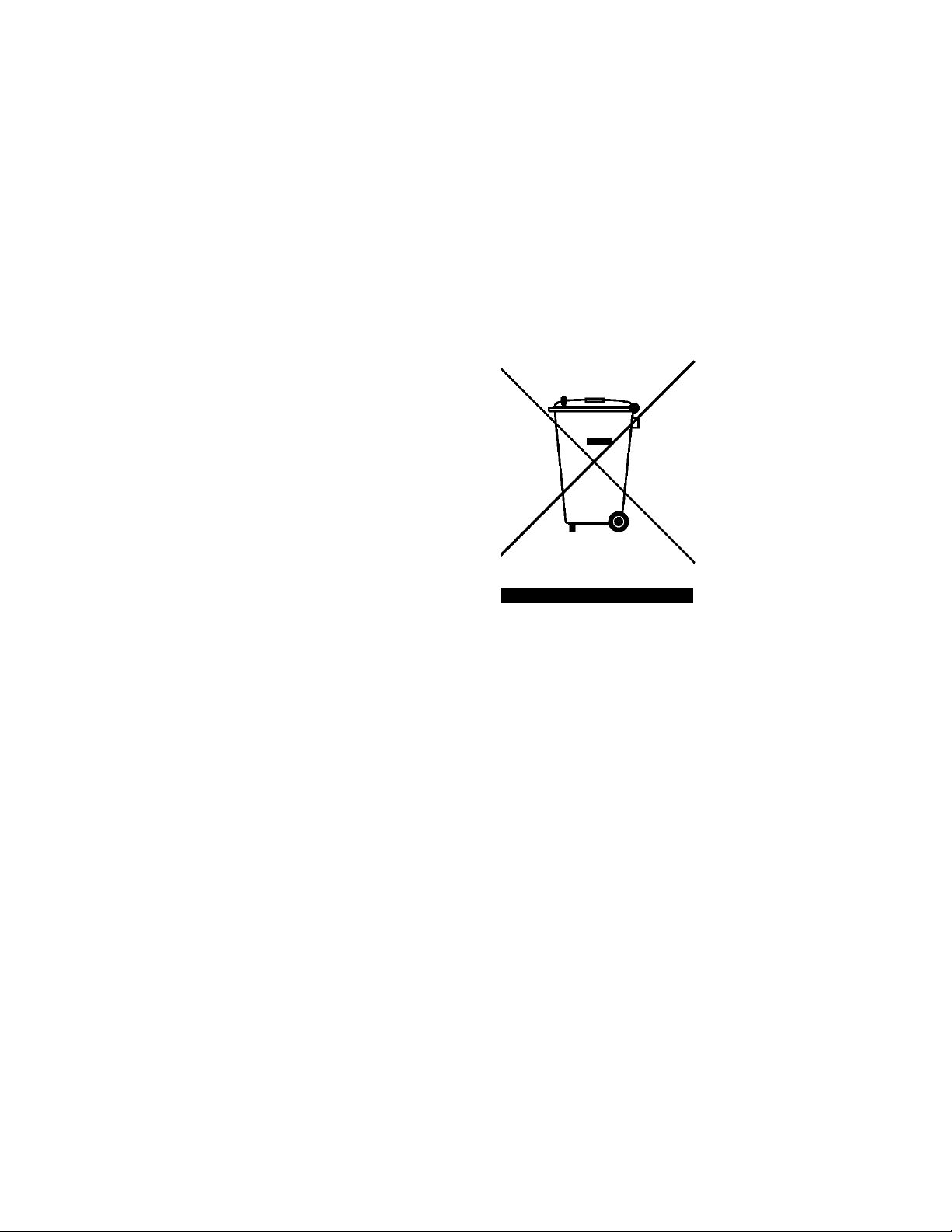
End of Life: Waste Electrical and Electronic Equipment (WEEE) Directive 2002/96/EC
This product complies with the WEEE Directive (2002/96/EC)
marking requirement. The affixed product label (see below)
indicates that you must not discard this electrical/electronic
product in domestic household waste.
Product Category:
With reference to the equipment types in the WEEE directive
Annex 1, this product is classified as a “Monitoring and Control
Instrumentation” product.
Do not dispose in domestic household waste
To return unwanted products, contact your local Keysight
office, or see:
http://www.keysight.com/environment/product
for more information.
2-8 TS-5020 Automotive Electronics Functional Test System Wiring Guide and Hardware Reference
Page 25

3 System Overview
System Intended Use .... 3-2
Instructions For Use .... 3-2
Test System Specifications and Capabilities .... 3-3
Test Capabilities – Measurement Sample Methods .... 3-4
System Capability DC Accuracy Sample .... 3-4
Test System Interface Description .... 3-6
Test System Interface Connectors .... 3-6
Rack Layout with Express Connect Test System Interface .... 3-28
Rack Layout with L2000 (TITAN) Test System Interface .... 3-29
System Block Diagrams with Express Connect Test System Interface ....
3-30
System Block Diagrams with L2000 (TITAN) Test System Interface .... 3-31
The Keysight 34980A Multifunction Switch/Measure Unit .... 3-32
Slot Allocation of the 34980A .... 3-32
PC Cards .... 3-36
Keysight 53131 Universal Counter .... 3-36
Keysight 53220 Universal Counter .... 3-36
Keysight 33220 Function/Arbitrary Waveform Generator .... 3-37
Power Supplies .... 3-37
Page 26

3 System Overview
WARNING
System Intended Use
Instructions For Use
The Keysight TS-5020 systems are designed to be used in high
volume Electronic Control Modules (ECM) manufacturing sites.
The systems can test ECU’s with 5-80 pins with voltages
0-60Vdc and currents in the 0-30Amp ranges. Typical
applications for TS-5020 system include testing of smart
sensors and ECMs for Antilock-brake, airbag, remote keyless
entry, climate control, sunroof and windows.
The Keysight TS-5020 systems contain all of the
instrumentation needed to test most electronics modules. You
may also add additional instruments and cabling to increase the
test capabilities of the system. The locations of the instruments
and test system interface or mass interconnect are standardized
as much as possible. Because the Keysight TS-5020 Series uses
open system standards, and is configurable by the system
integrator, systems at your site may be different from the
factory configurations.
In the event that additional instrumentation is added that will
shift the center of gravity, a rack stability test must be completed
to verify the stability of the modified rack.
Typical system operation is dependant on the target application. The
system is to be modified by trained personal for the target test module
application. Typically, the test system development process consists of:
• Identify the number of load resources required and assign load
resources
• Identify the number of measurement resources required and assign
measurement resources
• Identify ECM serial interface communications needs and assign
serial resource
• Identify fixture control resources required and assign I/O & power
resources
• Construct test fixture and test system interconnect cabling
required for the specific application
• Develop TXSL based test-plan for specific application
• Develop Software operator user interface for specific application
• Validate and deploy test system to manufacturing site.
3-2 TS-5020 Automotive Electronics Functional Test System Wiring Guide and Hardware Reference
Page 27

Test System Specifications and Capabilities
p
g
Ag ilent Technologies Quad 4x8 reed relay switch modu le.
34938A Agilent Technologies 20 Chann el, 5am p form A switch.
34951A Agilent Technologies 4 Channel isolated +/-16V DAC.
Ag ilent Technologies Un iversal Counter
33220A Agilent Technologies 20M hz Function/Arbitrary W aveform Generator
y
N6762A Agilent Technologies Power supply
y
N665xA Agilent Technologies Power supply
Agilent Technologies 21 slot switch/load unit
E6176A Agilent Technologies 16 Ch loadcard
E6178B Agilent Technologies 8 Ch Heavy Duty loadcard
N9377A Agilent Technologies 16 Ch dual load
Ag ilent Technologies 8 Ch low resistance loadca rd
The TS-5020 test system specifications are derived directly from
the specifications of the instrumentation that make up the
system. The overall test system measurement capability is a
combination of the measurement uncertainty as specified by
the individual instrumentation combined with the system
switch paths of the switching sub-systems.
For test system instrumentation specifications &
characteristics, refer directly to the manufacturer
documentation.
may be configured into the system. Refer to the manufacturer
supplied datasheets for detailed specifications.
Table 3-1 Typical TS-5020 Instrumentation
Table 3-1 lists various instrumentations that
System Overview 3
P/N Mfg Descri
34980A A
34933A
34934A Agilent Technologies Quad 4x32 Reed Matrix
34939A Agilent Technologies 64 Channel From A GP Sw itch
53131A
53220A Agilent Technologies 350 MH z Universal Frequency Co un ter /Tim e r
N6752A Agilent Technologie s P o w e r suppl
N664xA Agilent Technologie s P o w e r suppl
E6198B
E6175A Agilent Technologie s 8 C h loa dc ard
E6177A Agilent Technologies 24 Ch loadcard
U7177A Agilent Technologies 24 Ch loadcard with current sense
N9378A
N9379A Agilent Technologie s 4 8 C h high density loadcard
ilent Technologies 8 slot switch /m easu rem ent u nit w / d mm .
tion
TS-5020 Automotive Electronics Functional Test System Wiring Guide and Hardware Reference 3-3
Page 28

3 System Overview
Test Capabilities – Measurement Sample Methods
The following test capabilities calculations help you determine
if the Keysight TS-5020 Test System can meet your Electronic
Control Module (ECM) test requirements. The test capabilities
of the Keysight TS-5020 system include the specifications of the
individual instruments used in the test(s) combined with the
offsets in the system environment due to the measurement
paths. The largest contributors to measurement variations are
the instruments and the relays in the paths. The process for
determining system capabilities is:
• Determine the accuracy required to test the ECM. For example, a
particular output driver test measurement requires a measurement
of 12.5 volts ±10 mV.
• Determine the path, including the number of relays, to the DUT
from the based DMM.
• Determine the specification of the instrument from the module
manual specifications section for the particular range which will be
used for the test.
• Calculate the sum of the accuracy uncertainty due to instrument
modules' specifications and system switch paths, and compare it
to accuracy required by the DUT.
System Capability DC Accuracy Sample
relay in the measurement path needs to be included in the algorithm for
calculating the system-level capability. The source voltage of 12.5 volts
is supplied by Power Supply. The 1-year Accuracy vs. Aperture (±(% of
reading + volts)) specification of the Keysight 34980A internal DMM
for dc voltage on the 100-volt range for 16.7/20 milliseconds is
0.0045% + 0.6 millivolt.
The relays for the measurement system route through the 34933 matrix
card, and are all the specified at 50 microvolts offset.
The calculated system capability (accuracy) on the 100-volt range, using
16.7/20 millisecond aperture range, when using the Keysight 34980A
internal DMM within its defined accuracy conditions is:
3-4 TS-5020 Automotive Electronics Functional Test System Wiring Guide and Hardware Reference
Page 29

System Overview 3
DMM DC Accuracy + offset
+ relay V offset (DvmHi to abus1)
+ relay V offset (abus1 to Row matrix relay)
+ relay V offset (row matrix relay to abus2)
+ relay V offset (abus2 to DvmLo)
(This equals 4 relay offsets of 50uV each)
Calculated system capability = ±[(0.0045%*12.5 + 0.6 mV) + 4*50uV]
= ±1.36 mV
TS-5020 Automotive Electronics Functional Test System Wiring Guide and Hardware Reference 3-5
Page 30

3 System Overview
Test System Interface Description
The Keysight TS-5020 Test System Interface provides a common
connection interface between the test stand and your test
fixture/Unit Under Test (UUT). The Test System Interface
provides flexibility for specific test requirements and is
pre-wired and integrated to test stand equipment,
Test System Interface Connectors
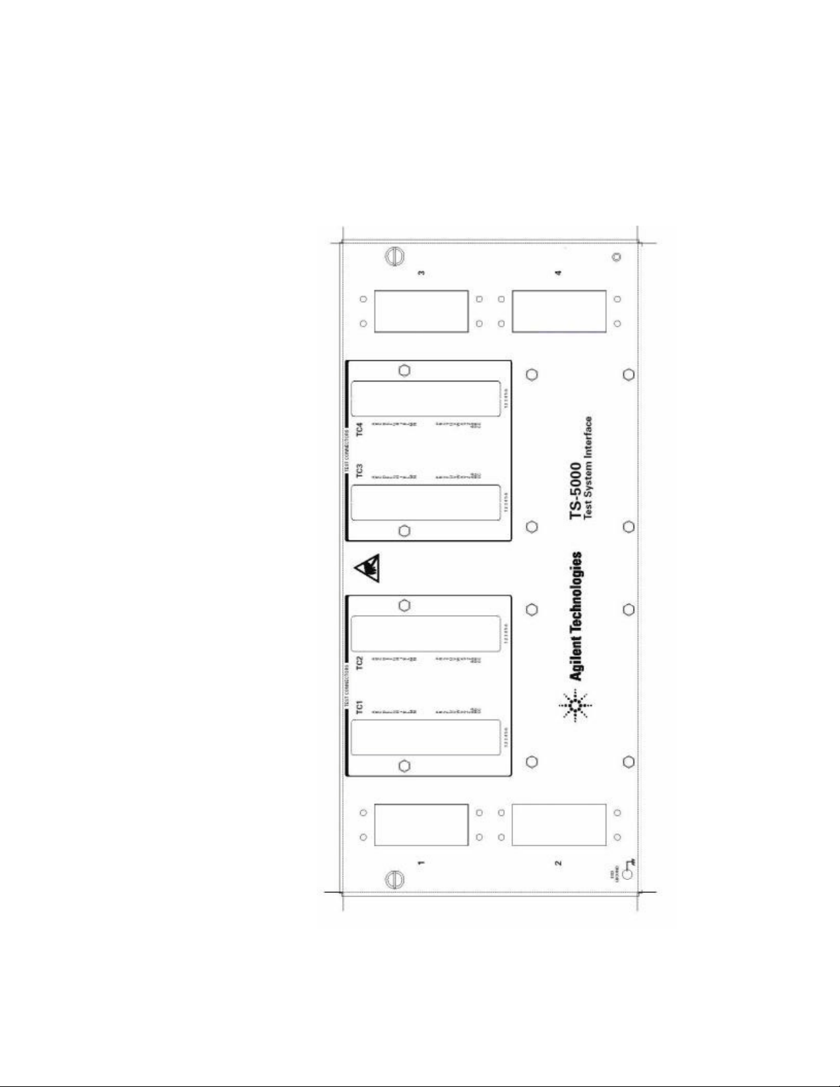
There two types of Test system Interface Connectors;
• Express Connect
• Macpanel L2000 (TITAN)
Express Connect Test System Interface
The Express Connect Test System Interface can contain either
of the following sets of test connectors:
• TC1 through TC4
• TC1 through TC8
Test connectors TC1 to TC4 or TC1 to TC8 provide the majority
of the connections to the UUT.
These connectors are 156-pin, ITT Cannon Zero-Insertion-Force
connectors.
Figure 3-1 and Figure 3-2 show the outline of the connector
sets.
3-6 TS-5020 Automotive Electronics Functional Test System Wiring Guide and Hardware Reference
Page 31
System Overview 3
Figure 3-1 Express Connect Test System Interface TC1 Through TC4
TS-5020 Automotive Electronics Functional Test System Wiring Guide and Hardware Reference 3-7
Page 32

3 System Overview
Figure 3-2 Express Connect Test system Interface TC1 Through TC8
3-8 TS-5020 Automotive Electronics Functional Test System Wiring Guide and Hardware Reference
Page 33

System Overview 3
Macpanel L2000 (TITAN) Test System Interface
The Macpanel L2000 (TITAN) Test system Interface contain
either of the of the following sets of test connectors:
• S1 - System
• S2 - Instruments
• S3 - DAC
• S4 - RS232
• S5 - User define
• S6 - Matrix card
• S7 - Matrix card
• S8 - Matrix card
• S9 - Matrix card
• S10 - GP Relay Card
• S11 - 24-CH Load Card
• S12 - GP Relay Card
• S13 - 24-CH Load Card/GP Relay Card
• S14 - 16-CH Load Card/GP Relay Card
• S15 - 48-CH Load Card/GP Relay Card
• S16 - Heavy Duty Load Card/Electronic Load
• S17 - 24-CH Load Card
• S18 - Heavy Duty Load Card
• S19 - 16-CH Load Card
• S20 - 48-CH Load Card
• S21 - Matrix card
• S22 - Matrix card
• S23 - Matrix card
• S24 - Matrix card
• S25 - RF Interconnection
Figure 3-3 shows the outline of the connector sets.
TS-5020 Automotive Electronics Functional Test System Wiring Guide and Hardware Reference 3-9
Page 34

3 System Overview
Figure 3-3 Macpanel L2000 (TITAN) Test System Interface
3-10 TS-5020 Automotive Electronics Functional Test System Wiring Guide and Hardware Reference
Page 35

System Overview 3
Tab l e 3 -2 L2000 (TITAN) Slot 1 (System)
Contact # Signal Contact # Signal Contact # Signal
1System Gnd33
2 Digital In (0) 34
3 Digital In (2) 35
4 Digital In (4) 36
5 Digital In (6) 37
6 Open Drain Out (0) 38
7 Open Drain Out (2) 39
8 Open Drain Out (4) 40
9 Open Drain Out (6) 41
10
11 Isense- (1) 43
12 Isense- (2) 44
13 Isense- (3) 45
14 Isense- (4) 46
15 PB Sense (1) 47
16 PB Sense (3) 48
17
18
19
20
21
22
23
24
25
26
27
28
29
30
31 +12Vdc supply 63
32 System Gnd 64
No connection 42 PCI1750 DI 74 No connection
No connection 49 PCI1750 DO 81 No connection
No connection 50 PCI1750 DO 82 No connection
No connection 51 PCI1750 DO 83 No connection
No connection 52 PCI1750 DO 84 No connection
No connection 53 PCI1750 DO 85 No connection
No connection 54 PCI1750 DO 86 No connection
No connection 55 PCI1750 DO 87 No connection
No connection 56 PCI1750 DO 88 No connection
No connection 57 PCI1750 DO 89 No connection
No connection 58 PCI1750 DO 90 TX+
No connection 59 PCI1750 DO 91 TX-
PCI1750Com 60 PCI1750 DO 92 RX+
PCI1750IGND 61 PCI1750 DO 93 RX-
No connection 62 PCI1750 DO 94 No connection
PCI1750 DI 65 System Gnd
PCI1750 DI 66 Digital In (1)
PCI1750 DI 67 Digital In (3)
PCI1750 DI 68 Digital In (5)
PCI1750 DI 69 Digital In (7)
PCI1750 DI 70 Open Drain Out (1)
PCI1750 DI 71 Open Drain Out (3)
PCI1750 DI 72 Open Drain Out (5)
PCI1750 DI 73 Open Drain Out (6)
PCI1750 DI 75 Isense+ (1)
PCI1750 DI 76 Isense+ (2)
PCI1750 DI 77 Isense+ (3)
PCI1750 DI 78 Isense+ (4)
PCI1750 DI 79 PB Sense (2)
PCI1750 DI 80 PB Sense (4)
PCI1750 DO 95 +24Vdc supply
PCI1750 DO 96 System Gnd
TS-5020 Automotive Electronics Functional Test System Wiring Guide and Hardware Reference 3-11
Page 36

3-12 TS-5020 Automotive Electronics Functional Test System Wiring Guide and Hardware Reference
Tab l e 3 -3 L2000 (TITAN) Slot 2 (Instruments)
Contact # Signal Contact # Signal Contact # Signal
10
11
12
13
14
15
16
17
18
19
20
21
22
23
24
25
26
27
28
29
30
31
32
1
2
3
4
5
6
7
8
9
com1 Gnd
com1 CD
com1 RTS
com2 Gnd
com2 CD
com2 RTS
CAN1.1(+) (softing1)
CAN1.2(+) (softing1)
Spare instrument(+)
Spare instrument(+)
Digitizer/DSO CH3_H
Digitizer/DSO CH4_H
Spare instrument(+)
Spare instrument(+)
Spare instrument(+)
Spare instrument(+)
Spare instrument(+)
Spare instrument(+)
Spare instrument(+)
Spare instrument(+)
Spare instrument(+)
DMM Ext Trig (+)
DMM Gnd
ChassisGND
DUT PS1(+)
DUT PS1(-)
DUT PS2(+)
DUT PS2(-)
DUT PS3(+)
DUT PS3(-)
DUT PS4(+)
DUT PS4(-)
33
34
35
36
37
38
39
40
41
42
43
44
45
46
47
48
49
50
51
52
53
54
55
56
57
58
59
60
61
62
63
64
com1 Rx
com1 DTR
com1 CTS
com2 Rx
com2 DTR
com2 CTS
CAN1.1(-) (softing1)
CAN1.2(-) (softing1)
Spare instrument(-)
Spare instrument(-)
Digitizer/DSO CH3_L
Digitizer/DSO CH4_L
Spare instrument(-)
Spare instrument(-)
Spare instrument(-)
Spare instrument(-)
Spare instrument(-)
Spare instrument(-)
Spare instrument(-)
Spare instrument(-)
Spare instrument(-)
No connection
No connection
ChassisGND
No connection
No connection
No connection
No connection
No connection
No connection
No connection
No connection
65
66
67
68
69
70
71
72
73
74
75
76
77
78
79
80
81
82
83
84
85
86
87
88
89
90
91
92
93
94
95
96
com1 DSR
com2 DSR
CAN1.1(shield) (softing1)
CAN1.2(shield) (softing1)
Spare instrument(shield)
Spare instrument(shield)
Spare instrument(shield)
Spare instrument(shield)
Spare instrument(shield)
Spare instrument(shield)
Spare instrument(shield)
Spare instrument(shield)
Spare instrument(shield)
Spare instrument(shield)
Spare instrument(shield)
Spare instrument(shield)
Spare instrument(shield)
No connection
No connection
ChassisGND
DUT PS1(S+)
DUT PS1(S-)
DUT PS2(S+)
DUT PS2(S-)
DUT PS3(S+)
DUT PS3(S-)
DUT PS4(S+)
DUT PS4(S-)
3 System Overview
com1 Tx
com1 RI
com2 Tx
com2 RI
Page 37

TS-5020 Automotive Electronics Functional Test System Wiring Guide and Hardware Reference 3-13
Tab l e 3 -4 L2000 (TITAN) Slot 3 (DAC)
Contact # Signal Contact # Signal Contact # Signal
1
2
3
4
5
6
7
8
9
10
11
12
13
14
15
16
17
18
19
20
21
22
23
24
25
26
27
28
29
30
31
32
DAC1 Ch1 Hi
DAC1 Ch1 Hi Sense
DAC1 Ch2 Hi
DAC1 Ch2 Hi Sense
DAC1 Ch3 Hi
DAC1 Ch3 Hi Sense
DAC1 Ch4 Hi
DAC1 Ch4 Hi Sense
DAC2 Ch1 Hi
DAC2 Ch1 Hi Sense
DAC2 Ch2 Hi
DAC2 Ch2 Hi Sense
DAC2 Ch3 Hi
DAC2 Ch3 Hi Sense
DAC2 Ch4 Hi
DAC2 Ch4 Hi Sense
DAC3 Ch1 Hi
DAC3 Ch1 Hi Sense
DAC3 Ch2 Hi
DAC3 Ch2 Hi Sense
DAC3 Ch3 Hi
DAC3 Ch3 Hi Sense
DAC3 Ch4 Hi
DAC3 Ch4 Hi Sense
DAC4 Ch1 Hi
DAC4 Ch1 Hi Sense
DAC4 Ch2 Hi
DAC4 Ch2 Hi Sense
DAC4 Ch3 Hi
DAC4 Ch3 Hi Sense
DAC4 Ch4 Hi
DAC4 Ch4 Hi Sense
33
34
35
36
37
38
39
40
41
42
43
44
45
46
47
48
49
50
51
52
53
54
55
56
57
58
59
60
61
62
63
64
DAC1 Ch1 Lo
DAC1 Ch1 Lo Sense
DAC1 Ch2 Lo
DAC1 Ch2 Lo Sense
DAC1 Ch3 Lo
DAC1 Ch3 Lo Sense
DAC1 Ch4 Lo
DAC1 Ch4 Lo Sense
DAC2 Ch1 Lo
DAC2 Ch1 Lo Sense
DAC2 Ch2 Lo
DAC2 Ch2 Lo Sense
DAC2 Ch3 Lo
DAC2 Ch3 Lo Sense
DAC2 Ch4 Lo
DAC2 Ch4 Lo Sense
DAC3 Ch1 Lo
DAC3 Ch1 Lo Sense
DAC3 Ch2 Lo
DAC3 Ch2 Lo Sense
DAC3 Ch3 Lo
DAC3 Ch3 Lo Sense
DAC3 Ch4 Lo
DAC3 Ch4 Lo Sense
DAC4 Ch1 Lo
DAC4 Ch1 Lo Sense
DAC4 Ch2 Lo
DAC4 Ch2 Lo Sense
DAC4 Ch3 Lo
DAC4 Ch3 Lo Sense
DAC4 Ch4 Lo
DAC4 Ch4 Lo Sense
65
66
67
68
69
70
71
72
73
74
75
76
77
78
79
80
81
82
83
84
85
86
87
88
89
90
91
92
93
94
95
96
DAC1 Trigger
DAC1 Ext Clk
DAC1 Gnd
DAC1 Gnd
No Connection
No Connection
No Connection
No Connection
DAC2 Trigger
DAC2 Ext Clk
DAC2 Gnd
DAC2 Gnd
No Connection
No Connection
No Connection
No Connection
DAC3 Trigger
DAC3 Ext Clk
DAC3 Gnd
DAC3 Gnd
No Connection
No Connection
No Connection
No Connection
DAC4 Trigger
DAC4 Ext Clk
DAC4 Gnd
DAC4 Gnd
No Connection
No Connection
No Connection
No Connection
System Overview 3
Page 38

3-14 TS-5020 Automotive Electronics Functional Test System Wiring Guide and Hardware Reference
Tab l e 3 -5 L2000 (TITAN) Slot 4 (RS232)
Contact # signal Contact # signal Contact # signal
1
2
3
4
5
6
7
8
9
10
11
12
13
14
15
16
17
18
19
20
21
22
23
24
25
26
27
28
29
30
31
32
com3 Gnd
com3 CD
com3 RTS
com4 Gnd
com4 CD
com4 RTS
com5 Gnd
com5 CD
com5 RTS
com6 Gnd
com6 CD
com6 RTS
com7 Gnd
com7 CD
com7 RTS
com8 Gnd
com8 CD
com8 RTS
com9 Gnd
com9 CD
com9 RTS
com10 Gnd
com10 CD
com10 RTS
No Connection
No Connection
No Connection
No Connection
No Connection
No Connection
No Connection
No Connection
33
34
35
36
37
38
39
40
41
42
43
44
45
46
47
48
49
50
51
52
53
54
55
56
57
58
59
60
61
62
63
64
com3 Rx
com3 DTR
com3 CTS
com4 Rx
com4 DTR
com4 CTS
com5 Rx
com5 DTR
com5 CTS
com6 Rx
com6 DTR
com6 CTS
com7 Rx
com7 DTR
com7 CTS
co8 Rx
com8 DTR
com8 CTS
com9 Rx
com9 DTR
com9 Rx
com10 Rx
com10 DTR
com10 CTS
No Connection
No Connection
No Connection
No Connection
No Connection
No Connection
No Connection
No Connection
65
66
67
68
69
70
71
72
73
74
75
76
77
78
79
80
81
82
83
84
85
86
87
88
89
90
91
92
93
94
95
96
com10 DSR
No Connection
No Connection
No Connection
No Connection
No Connection
No Connection
No Connection
No Connection
3 System Overview
com3 Tx
com3 DSR
com3 RI
com4 Tx
com4 DSR
com4 RI
com5 Tx
com5 DSR
com5 RI
com6 Tx
com6 DSR
com6 RI
com7 Tx
com7 DSR
com7 RI
com8 Tx
com8 DSR
com8 RI
com9 Tx
com9 DSR
com9 RI
com10 Tx
com10 RI
Page 39

System Overview 3
Tab l e 3 -6 L2000 (TITAN) Slot 6 (Pin Matrix 1st Card 34933A)
Contact # Signal Contact # Signal Contact # Signal
10
11
12
13
14
15
16
17
18
19
20
21
22
23
24
25
26
27
28
29
30
31
32
1
2
3
4
5
6
7
8
9
matrix001.row1
matrix001.row2
matrix001.row3
matrix001.row4
matrix001.row5
matrix001.row6
matrix001.row7
matrix001.row8
matrix001.row9
matrix001.row10
matrix001.row11
matrix001.row12
matrix001.row13
matrix001.row14
matrix001.row15
matrix001.row16
No Connection
No Connection
No Connection
No Connection
No Connection
No Connection
No Connection
No Connection
No Connection
No Connection
No Connection
No Connection
No Connection
No Connection
No Connection
No Connection
33
34
35
36
37
38
39
40
41
42
43
44
45
46
47
48
49
50
51
52
53
54
55
56
57
58
59
60
61
62
63
64
No Connection
No Connection
No Connection
No Connection
No Connection
No Connection
No Connection
No Connection
No Connection
No Connection
No Connection
No Connection
No Connection
No Connection
No Connection
No Connection
No Connection
No Connection
No Connection
No Connection
No Connection
No Connection
No Connection
No Connection
No Connection
No Connection
No Connection
No Connection
No Connection
No Connection
No Connection
No Connection
65
66
67
68
69
70
71
72
73
74
75
76
77
78
79
80
81
82
83
84
85
86
87
88
89
90
91
92
93
94
95
96
UUTCOM
UUTCOM
UUTCOM
UUTCOM
UUTCOM
UUTCOM
UUTCOM
UUTCOM
UUTCOM
UUTCOM
UUTCOM
UUTCOM
UUTCOM
UUTCOM
UUTCOM
UUTCOM
No Connection
No Connection
No Connection
No Connection
No Connection
No Connection
No Connection
No Connection
No Connection
No Connection
No Connection
No Connection
No Connection
No Connection
No Connection
No Connection
TS-5020 Automotive Electronics Functional Test System Wiring Guide and Hardware Reference 3-15
Page 40

3 System Overview
Tab l e 3 - 7 L2000 (TITAN) Slot 7 to 9 (Matrix Card 34933A)
Contact # Signal Contact # Signal Contact # Signal
1
2
3
4
5
6
7
8
9
10
11
12
13
14
15
16
17
18
19
20
21
22
23
24
25
26
27
28
29
30
31
32
matrix00x.row1
matrix00x.row2
matrix00x.row3
matrix00x.row4
matrix00x.row5
matrix00x.row6
matrix00x.row7
matrix00x.row8
matrix00x.row9
matrix00x.row10
matrix00x.row11
matrix00x.row12
matrix00x.row13
matrix00x.row14
matrix00x.row15
matrix00x.row16
matrix00x.row17
matrix00x.row18
matrix00x.row19
matrix00x.row20
matrix00x.row21
matrix00x.row22
matrix00x.row23
matrix00x.row24
matrix00x.row25
matrix00x.row26
matrix00x.row27
matrix00x.row28
matrix00x.row29
matrix00x.row30
matrix00x.row31
matrix00x.row32
33
34
35
36
37
38
39
40
41
42
43
44
45
46
47
48
49
50
51
52
53
54
55
56
57
58
59
60
61
62
63
64
No Connection
No Connection
No Connection
No Connection
No Connection
No Connection
No Connection
No Connection
No Connection
No Connection
No Connection
No Connection
No Connection
No Connection
No Connection
No Connection
No Connection
No Connection
No Connection
No Connection
No Connection
No Connection
No Connection
No Connection
No Connection
No Connection
No Connection
No Connection
No Connection
No Connection
No Connection
No Connection
65
66
67
68
69
70
71
72
73
74
75
76
77
78
79
80
81
82
83
84
85
86
87
88
89
90
91
92
93
94
95
96
UUTCOM
UUTCOM
UUTCOM
UUTCOM
UUTCOM
UUTCOM
UUTCOM
UUTCOM
UUTCOM
UUTCOM
UUTCOM
UUTCOM
UUTCOM
UUTCOM
UUTCOM
UUTCOM
UUTCOM
UUTCOM
UUTCOM
UUTCOM
UUTCOM
UUTCOM
UUTCOM
UUTCOM
UUTCOM
UUTCOM
UUTCOM
UUTCOM
UUTCOM
UUTCOM
UUTCOM
UUTCOM
3-16 TS-5020 Automotive Electronics Functional Test System Wiring Guide and Hardware Reference
Page 41

TS-5020 Automotive Electronics Functional Test System Wiring Guide and Hardware Reference 3-17
Tab l e 3 -8 L2000 (TITAN) Slot 6 (Pin Matrix 1st Card (34934A))
Contact # signal Contact # signal Contact # signal
10
11
12
13
14
15
16
17
18
19
20
21
22
23
24
25
26
27
28
29
30
31
32
1
2
3
4
5
6
7
8
9
matrix001.row1
matrix001.row2
matrix001.row3
matrix001.row4
matrix001.row5
matrix001.row6
matrix001.row7
matrix001.row8
matrix001.row9
matrix001.row10
matrix001.row11
matrix001.row12
matrix001.row13
matrix001.row14
matrix001.row15
matrix001.row16
matrix001.row17
matrix001.row18
matrix001.row19
matrix001.row20
matrix001.row21
matrix001.row22
matrix001.row23
matrix001.row24
matrix001.row25
matrix001.row26
matrix001.row27
matrix001.row28
matrix001.row29
matrix001.row30
matrix001.row31
matrix001.row32
33
34
35
36
37
38
39
40
41
42
43
44
45
46
47
48
49
50
51
52
53
54
55
56
57
58
59
60
61
62
63
64
matrix001.Inst17
matrix001.Inst18
matrix001.Inst19
matrix001.Inst20
matrix001.Inst21
matrix001.Inst22
matrix001.Inst23
matrix001.Inst24
matrix001.Inst25
matrix001.Inst26
matrix001.Inst27
matrix001.Inst28
matrix001.Inst29
matrix001.Inst30
matrix001.Inst31
matrix001.Inst32
No connection
No connection
No connection
No connection
No connection
No connection
No connection
No connection
No connection
No connection
No connection
No connection
No connection
No connection
No connection
No connection
65
66
67
68
69
70
71
72
73
74
75
76
77
78
79
80
81
82
83
84
85
86
87
88
89
90
91
92
93
94
95
96
UUTCOM
UUTCOM
UUTCOM
UUTCOM
UUTCOM
UUTCOM
UUTCOM
UUTCOM
UUTCOM
UUTCOM
UUTCOM
UUTCOM
UUTCOM
UUTCOM
UUTCOM
UUTCOM
UUTCOM
UUTCOM
UUTCOM
UUTCOM
UUTCOM
UUTCOM
UUTCOM
UUTCOM
UUTCOM
UUTCOM
UUTCOM
UUTCOM
UUTCOM
UUTCOM
UUTCOM
UUTCOM
System Overview 3
Page 42

3-18 TS-5020 Automotive Electronics Functional Test System Wiring Guide and Hardware Reference
Tab l e 3 -9 L2000 (TITAN) Slot 7 (Pin Matrix 1st Card (34934A))
Contact # Signal Contact # Signal Contact # Signal
10
11
12
13
14
15
16
17
18
19
20
21
22
23
24
25
26
27
28
29
30
31
32
1
2
3
4
5
6
7
8
9
matrix001.row33
matrix001.row34
matrix001.row35
matrix001.row36
matrix001.row37
matrix001.row38
matrix001.row39
matrix001.row40
matrix001.row41
matrix001.row42
matrix001.row43
matrix001.row44
matrix001.row45
matrix001.row46
matrix001.row47
matrix001.row48
matrix001.row49
matrix001.row50
matrix001.row51
matrix001.row52
matrix001.row53
matrix001.row54
matrix001.row55
matrix001.row56
matrix001.row57
matrix001.row58
matrix001.row59
matrix001.row60
matrix001.row61
matrix001.row62
matrix001.row63
matrix001.row64
33
34
35
36
37
38
39
40
41
42
43
44
45
46
47
48
49
50
51
52
53
54
55
56
57
58
59
60
61
62
63
64
matrix001.row65
matrix001.row66
matrix001.row67
matrix001.row68
matrix001.row69
matrix001.row70
matrix001.row71
matrix001.row72
matrix001.row73
matrix001.row74
matrix001.row75
matrix001.row76
matrix001.row77
matrix001.row78
matrix001.row79
matrix001.row80
matrix001.row81
matrix001.row82
matrix001.row83
matrix001.row84
matrix001.row85
matrix001.row86
matrix001.row87
matrix001.row88
matrix001.row89
matrix001.row90
matrix001.row91
matrix001.row92
matrix001.row93
matrix001.row94
matrix001.row95
matrix001.row96
65
66
67
68
69
70
71
72
73
74
75
76
77
78
79
80
81
82
83
84
85
86
87
88
89
90
91
92
93
94
95
96
3 System Overview
UUTCOM
UUTCOM
UUTCOM
UUTCOM
UUTCOM
UUTCOM
UUTCOM
UUTCOM
UUTCOM
UUTCOM
UUTCOM
UUTCOM
UUTCOM
UUTCOM
UUTCOM
UUTCOM
UUTCOM
UUTCOM
UUTCOM
UUTCOM
UUTCOM
UUTCOM
UUTCOM
UUTCOM
UUTCOM
UUTCOM
UUTCOM
UUTCOM
UUTCOM
UUTCOM
UUTCOM
UUTCOM
Page 43

TS-5020 Automotive Electronics Functional Test System Wiring Guide and Hardware Reference 3-19
Table 3-10 L2000 (TITAN) Slot 8/21/23 (Pin Matrix Card (34934A))
Contact # Signal Contact # Signal Contact # Signal
1
2
3
4
5
6
7
8
9
10
11
12
13
14
15
16
17
18
19
20
21
22
23
24
25
26
27
28
29
30
31
32
matrix00x.row1
matrix00x.row2
matrix00x.row3
matrix00x.row4
matrix00x.row5
matrix00x.row6
matrix00x.row7
matrix00x.row8
matrix00x.row9
matrix00x.row10
matrix00x.row11
matrix00x.row12
matrix00x.row13
matrix00x.row14
matrix00x.row15
matrix00x.row16
matrix00x.row17
matrix00x.row18
matrix00x.row19
matrix00x.row20
matrix00x.row21
matrix00x.row22
matrix00x.row23
matrix00x.row24
matrix00x.row25
matrix00x.row26
matrix00x.row27
matrix00x.row28
matrix00x.row29
matrix00x.row30
matrix00x.row31
matrix00x.row32
33
34
35
36
37
38
39
40
41
42
43
44
45
46
47
48
49
50
51
52
53
54
55
56
57
58
59
60
61
62
63
64
matrix00x.row33
matrix00x.row34
matrix00x.row35
matrix00x.row36
matrix00x.row37
matrix00x.row38
matrix00x.row39
matrix00x.row40
matrix00x.row41
matrix00x.row42
matrix00x.row43
matrix00x.row44
matrix00x.row45
matrix00x.row46
matrix00x.row47
matrix00x.row48
matrix00x.row49
matrix00x.row50
matrix00x.row51
matrix00x.row52
matrix00x.row53
matrix00x.row54
matrix00x.row55
matrix00x.row56
matrix00x.row57
matrix00x.row58
matrix00x.row59
matrix00x.row60
matrix00x.row61
matrix00x.row62
matrix00x.row63
matrix00x.row64
65
66
67
68
69
70
71
72
73
74
75
76
77
78
79
80
81
82
83
84
85
86
87
88
89
90
91
92
93
94
95
96
UUTCOM
UUTCOM
UUTCOM
UUTCOM
UUTCOM
UUTCOM
UUTCOM
UUTCOM
UUTCOM
UUTCOM
UUTCOM
UUTCOM
UUTCOM
UUTCOM
UUTCOM
UUTCOM
UUTCOM
UUTCOM
UUTCOM
UUTCOM
UUTCOM
UUTCOM
UUTCOM
UUTCOM
UUTCOM
UUTCOM
UUTCOM
UUTCOM
UUTCOM
UUTCOM
UUTCOM
UUTCOM
System Overview 3
Page 44

3-20 TS-5020 Automotive Electronics Functional Test System Wiring Guide and Hardware Reference
Table 3-11 L2000 (TITAN) Slot 9/22/24 (Pin Matrix Card (34934A))
Contact # Signal Contact # Signal Contact # Signal
1
2
3
4
5
6
7
8
9
10
11
12
13
14
15
16
17
18
19
20
21
22
23
24
25
26
27
28
29
30
31
32
matrix00x.row65
matrix00x.row66
matrix00x.row67
matrix00x.row68
matrix00x.row69
matrix00x.row70
matrix00x.row71
matrix00x.row72
matrix00x.row73
matrix00x.row74
matrix00x.row75
matrix00x.row76
matrix00x.row77
matrix00x.row78
matrix00x.row79
matrix00x.row80
matrix00x.row81
matrix00x.row82
matrix00x.row83
matrix00x.row84
matrix00x.row85
matrix00x.row86
matrix00x.row87
matrix00x.row88
matrix00x.row89
matrix00x.row90
matrix00x.row91
matrix00x.row92
matrix00x.row93
matrix00x.row94
matrix00x.row95
matrix00x.row96
33
34
35
36
37
38
39
40
41
42
43
44
45
46
47
48
49
50
51
52
53
54
55
56
57
58
59
60
61
62
63
64
matrix00x.row97
matrix00x.row98
matrix00x.row99
matrix00x.row100
matrix00x.row101
matrix00x.row102
matrix00x.row103
matrix00x.row104
matrix00x.row105
matrix00x.row106
matrix00x.row107
matrix00x.row108
matrix00x.row109
matrix00x.row110
matrix00x.row111
matrix00x.row112
matrix00x.row113
matrix00x.row114
matrix00x.row115
matrix00x.row116
matrix00x.row117
matrix00x.row118
matrix00x.row119
matrix00x.row120
matrix00x.row121
matrix00x.row122
matrix00x.row123
matrix00x.row124
matrix00x.row125
matrix00x.row126
matrix00x.row127
matrix00x.row128
65
66
67
68
69
70
71
72
73
74
75
76
77
78
79
80
81
82
83
84
85
86
87
88
89
90
91
92
93
94
95
96
UUTCOM
UUTCOM
UUTCOM
UUTCOM
UUTCOM
UUTCOM
UUTCOM
UUTCOM
UUTCOM
UUTCOM
UUTCOM
UUTCOM
UUTCOM
UUTCOM
UUTCOM
UUTCOM
UUTCOM
UUTCOM
UUTCOM
UUTCOM
UUTCOM
UUTCOM
UUTCOM
UUTCOM
UUTCOM
UUTCOM
UUTCOM
UUTCOM
UUTCOM
UUTCOM
UUTCOM
UUTCOM
3 System Overview
Page 45

System Overview 3
Table 3-12 L2000 (TITAN) Slot 12 to 15 (GP relay Card (34938A))
Contact # Signal Contact # Signal Contact # Signal
1
2
3
4
5
6
7
8
9
10
11
12
13
14
15
16
17
18
19
20
21
22
23
24
25
26
27
28
29
30
31
32
loadcard00x.Ch1
loadcard00x.Ch2
loadcard00x.Ch3
loadcard00x.Ch4
loadcard00x.Ch5
loadcard00x.Ch6
loadcard00x.Ch7
loadcard00x.Ch8
loadcard00x.Ch9
loadcard00x.Ch10
loadcard00x.Ch11
loadcard00x.Ch12
loadcard00x.Ch13
loadcard00x.Ch14
loadcard00x.Ch15
loadcard00x.Ch16
loadcard00x.Ch17
loadcard00x.Ch18
loadcard00x.Ch19
loadcard00x.Ch20
No Connection
No Connection
No Connection
No Connection
No Connection
No Connection
No Connection
No Connection
No Connection
No Connection
No Connection
No Connection
33
34
35
36
37
38
39
40
41
42
43
44
45
46
47
48
49
50
51
52
53
54
55
56
57
58
59
60
61
62
63
64
No Connection
No Connection
No Connection
No Connection
No Connection
No Connection
No Connection
No Connection
No Connection
No Connection
No Connection
No Connection
No Connection
No Connection
No Connection
No Connection
No Connection
No Connection
No Connection
No Connection
No Connection
No Connection
No Connection
No Connection
No Connection
No Connection
No Connection
No Connection
No Connection
No Connection
No Connection
No Connection
65
66
67
68
69
70
71
72
73
74
75
76
77
78
79
80
81
82
83
84
85
86
87
88
89
90
91
92
93
94
95
96
loadcard00x.Pwr1
loadcard00x.Pwr2
loadcard00x.Pwr3
loadcard00x.Pwr4
loadcard00x.Pwr5
loadcard00x.Pwr6
loadcard00x.Pwr7
loadcard00x.Pwr8
loadcard00x.Pwr9
loadcard00x.Pwr10
loadcard00x.Pwr11
loadcard00x.Pwr12
loadcard00x.Pwr13
loadcard00x.Pwr14
loadcard00x.Pwr15
loadcard00x.Pwr16
loadcard00x.Pwr17
loadcard00x.Pwr18
loadcard00x.Pwr19
loadcard00x.Pwr20
No Connection
No Connection
No Connection
No Connection
No Connection
No Connection
No Connection
No Connection
No Connection
No Connection
No Connection
No Connection
TS-5020 Automotive Electronics Functional Test System Wiring Guide and Hardware Reference 3-21
Page 46

3 System Overview
Table 3-13 L2000 (TITAN) Slot 12 to 15 (GP relay Card (34939A))
Contact # Signal Contact # Signal Contact # Signal
1
2
3
4
5
6
7
8
9
10
11
12
13
14
15
16
17
18
19
20
21
22
23
24
25
26
27
28
29
30
31
32
loadcard00x.Ch1
loadcard00x.Ch3
loadcard00x.Ch5
loadcard00x.Ch7
loadcard00x.Ch9
loadcard00x.Ch11
loadcard00x.Ch13
loadcard00x.Ch15
loadcard00x.Ch17
loadcard00x.Ch19
loadcard00x.Ch21
loadcard00x.Ch23
loadcard00x.Ch25
loadcard00x.Ch27
loadcard00x.Ch29
loadcard00x.Ch31
loadcard00x.Ch33
loadcard00x.Ch35
loadcard00x.Ch37
loadcard00x.Ch39
loadcard00x.Ch41
loadcard00x.Ch43
loadcard00x.Ch45
loadcard00x.Ch47
loadcard00x.Ch49
loadcard00x.Ch51
loadcard00x.Ch53
loadcard00x.Ch55
loadcard00x.Ch57
loadcard00x.Ch59
loadcard00x.Ch61
loadcard00x.Ch63
33
34
35
36
37
38
39
40
41
42
43
44
45
46
47
48
49
50
51
52
53
54
55
56
57
58
59
60
61
62
63
64
loadcard00x.Ch2
loadcard00x.Ch4
loadcard00x.Ch6
loadcard00x.Ch8
loadcard00x.Ch10
loadcard00x.Ch12
loadcard00x.Ch14
loadcard00x.Ch16
loadcard00x.Ch18
loadcard00x.Ch20
loadcard00x.Ch22
loadcard00x.Ch24
loadcard00x.Ch26
loadcard00x.Ch28
loadcard00x.Ch30
loadcard00x.Ch32
loadcard00x.Ch34
loadcard00x.Ch36
loadcard00x.Ch38
loadcard00x.Ch40
loadcard00x.Ch42
loadcard00x.Ch44
loadcard00x.Ch46
loadcard00x.Ch48
loadcard00x.Ch50
loadcard00x.Ch52
loadcard00x.Ch54
loadcard00x.Ch56
loadcard00x.Ch58
loadcard00x.Ch60
loadcard00x.Ch62
loadcard00x.Ch64
65
66
67
68
69
70
71
72
73
74
75
76
77
78
79
80
81
82
83
84
85
86
87
88
89
90
91
92
93
94
95
96
loadcard00x.Pwr1-2
loadcard00x.Pwr3-4
loadcard00x.Pwr5-6
loadcard00x.Pwr7-8
loadcard00x.Pwr9-10
loadcard00x.Pwr11-12
loadcard00x.Pwr13-14
loadcard00x.Pwr15-16
loadcard00x.Pwr17-18
loadcard00x.Pwr19-20
loadcard00x.Pwr21-22
loadcard00x.Pwr23-24
loadcard00x.Pwr25-26
loadcard00x.Pwr27-28
loadcard00x.Pwr29-30
loadcard00x.Pwr31-32
loadcard00x.Pwr33-34
loadcard00x.Pwr35-36
loadcard00x.Pwr37-38
loadcard00x.Pwr39-40
loadcard00x.Pwr41-42
loadcard00x.Pwr43-44
loadcard00x.Pwr45-46
loadcard00x.Pwr47-48
loadcard00x.Pwr49-50
loadcard00x.Pwr51-52
loadcard00x.Pwr53-54
loadcard00x.Pwr55-56
loadcard00x.Pwr57-58
loadcard00x.Pwr59-60
loadcard00x.Pwr61-62
loadcard00x.Pwr63-64
3-22 TS-5020 Automotive Electronics Functional Test System Wiring Guide and Hardware Reference
Page 47

System Overview 3
Table 3-14 L2000 (TITAN) Slot 11 to 20 (24-CH Load Card)
Wiring Table for E6177A/U7177A/N9378A
Contact # Signal Contact # Signal Contact # Signal
10
11
12
13
14
15
16
17
18
19
20
21
22
23
24
25
26
27
28
29
30
31
32
1
2
3
4
5
6
7
8
9
loadcard10x.Ch1
loadcard10x.Ch2
loadcard10x.Ch3
loadcard10x.Ch4
loadcard10x.Ch5
loadcard10x.Ch6
loadcard10x.Ch7
loadcard10x.Ch8
loadcard10x.Ch9
loadcard10x.Ch10
loadcard10x.Ch11
loadcard10x.Ch12
loadcard10x.Ch13
loadcard10x.Ch14
loadcard10x.Ch15
loadcard10x.Ch16
loadcard10x.Ch17
loadcard10x.Ch18
loadcard10x.Ch19
loadcard10x.Ch20
loadcard10x.Ch21
loadcard10x.Ch22
loadcard10x.Ch23
loadcard10x.Ch24
loadcard10y.Ch1
loadcard10y.Ch23
loadcard10y.Ch3
loadcard10y.Ch4
loadcard10y.Ch5
loadcard10y.Ch6
loadcard10y.Ch7
loadcard10y.Ch8
33
34
35
36
37
38
39
40
41
42
43
44
45
46
47
48
49
50
51
52
53
54
55
56
57
58
59
60
61
62
63
64
loadcard10y.Ch9
loadcard10y.Ch10
loadcard10y.Ch11
loadcard10y.Ch12
loadcard10y.Ch13
loadcard10y.Ch14
loadcard10y.Ch15
loadcard10y.Ch16
loadcard10y.Ch17
loadcard10y.Ch18
loadcard10y.Ch19
loadcard10y.Ch20
loadcard10y.Ch21
loadcard10y.Ch22
loadcard10y.Ch23
loadcard10y.Ch24
loadcard10y.Pwr9
loadcard10y.Pwr10
loadcard10y.Pwr11
loadcard10y.Pwr12
loadcard10y.Pwr13
loadcard10y.Pwr14
loadcard10y.Pwr15
loadcard10y.Pwr16
loadcard10y.Pwr17
loadcard10y.Pwr18
loadcard10y.Pwr19
loadcard10y.Pwr20
loadcard10y.Pwr21
loadcard10y.Pwr22
loadcard10y.Pwr23
loadcard10y.Pwr24
65
66
67
68
69
70
71
72
73
74
75
76
77
78
79
80
81
82
83
84
85
86
87
88
89
90
91
92
93
94
95
96
loadcard10x.Pwr1
loadcard10x.Pwr2
loadcard10x.Pwr3
loadcard10x.Pwr4
loadcard10x.Pwr5
loadcard10x.Pwr6
loadcard10x.Pwr7
loadcard10x.Pwr8
loadcard10x.Pwr9
loadcard10x.Pwr10
loadcard10x.Pwr11
loadcard10x.Pwr12
loadcard10x.Pwr13
loadcard10x.Pwr14
loadcard10x.Pwr15
loadcard10x.Pwr16
loadcard10x.Pwr17
loadcard10x.Pwr18
loadcard10x.Pwr19
loadcard10x.Pwr20
loadcard10x.Pwr21
loadcard10x.Pwr22
loadcard10x.Pwr23
loadcard10x.Pwr24
loadcard10y.Pwr1
loadcard10y.Pwr2
loadcard10y.Pwr3
loadcard10y.Pwr4
loadcard10y.Pwr5
loadcard10y.Pwr6
loadcard10y.Pwr7
loadcard10y.Pwr8
TS-5020 Automotive Electronics Functional Test System Wiring Guide and Hardware Reference 3-23
Page 48

3 System Overview
Table 3-15 L2000 (TITAN) Slot 13 to 20 (16-CH Load Card)
Wiring Table for E6176A/N9377A
Contact # Signal Contact # Signal Contact # Signal
1
2
3
4
5
6
7
8
9
10
11
12
13
14
15
16
17
18
19
20
21
22
23
24
25
26
27
28
29
30
31
32
loadcard10x.Ch1
loadcard10x.Ch2
loadcard10x.Ch3
loadcard10x.Ch4
loadcard10x.Ch5
loadcard10x.Ch6
loadcard10x.Ch7
loadcard10x.Ch8
loadcard10x.Ch9
loadcard10x.Ch10
loadcard10x.Ch11
loadcard10x.Ch12
loadcard10x.Ch13
loadcard10x.Ch14
loadcard10x.Ch15
loadcard10x.Ch16
loadcard10y.Ch1
loadcard10y.Ch2
loadcard10y.Ch3
loadcard10y.Ch4
loadcard10y.Ch5
loadcard10y.Ch6
loadcard10y.Ch7
loadcard10y.Ch8
loadcard10y.Ch9
loadcard10y.Ch10
loadcard10y.Ch11
loadcard10y.Ch12
loadcard10y.Ch13
loadcard10y.Ch14
loadcard10y.Ch15
loadcard10y.Ch16
33
34
35
36
37
38
39
40
41
42
43
44
45
46
47
48
49
50
51
52
53
54
55
56
57
58
59
60
61
62
63
64
No Connection
No Connection
No Connection
No Connection
No Connection
No Connection
No Connection
No Connection
No Connection
No Connection
No Connection
No Connection
No Connection
No Connection
No Connection
No Connection
No Connection
No Connection
No Connection
No Connection
No Connection
No Connection
No Connection
No Connection
No Connection
No Connection
No Connection
No Connection
No Connection
No Connection
No Connection
No Connection
65
66
67
68
69
70
71
72
73
74
75
76
77
78
79
80
81
82
83
84
85
86
87
88
89
90
91
92
93
94
95
96
loadcard10w.Ch1
loadcard10w.Ch2
loadcard10w.Ch3
loadcard10w.Ch4
loadcard10w.Ch5
loadcard10w.Ch6
loadcard10w.Ch7
loadcard10w.Ch8
loadcard10w.Ch9
loadcard10w.Ch10
loadcard10w.Ch11
loadcard10w.Ch12
loadcard10w.Ch13
loadcard10w.Ch14
loadcard10w.Ch15
loadcard10w.Ch16
loadcard10z.Ch1
loadcard10z.Ch2
loadcard10z.Ch3
loadcard10z.Ch4
loadcard10z.Ch5
loadcard10z.Ch6
loadcard10z.Ch7
loadcard10z.Ch8
loadcard10z.Ch9
loadcard10z.Ch10
loadcard10z.Ch11
loadcard10z.Ch12
loadcard10z.Ch13
loadcard10z.Ch14
loadcard10z.Ch15
loadcard10z.Ch16
3-24 TS-5020 Automotive Electronics Functional Test System Wiring Guide and Hardware Reference
Page 49

System Overview 3
Table 3-16 L2000 (TITAN) Slot 13 to 20 (48-CH Load Card)
Wiring Table for N9379A
Contact # Signal Contact # Signal Contact # Signal
10
11
12
13
14
15
16
17
18
19
20
21
22
23
24
25
26
27
28
29
30
31
32
1
2
3
4
5
6
7
8
9
loadcard10x.Ch1
loadcard10x.Ch2
loadcard10x.Ch3
loadcard10x.Ch4
loadcard10x.Ch5
loadcard10x.Ch6
loadcard10x.Ch7
loadcard10x.Ch8
loadcard10x.Ch9
loadcard10x.Ch10
loadcard10x.Ch11
loadcard10x.Ch12
loadcard10x.Ch13
loadcard10x.Ch14
loadcard10x.Ch15
loadcard10x.Ch16
loadcard10x.Ch17
loadcard10x.Ch18
loadcard10x.Ch19
loadcard10x.Ch20
loadcard10x.Ch21
loadcard10x.Ch22
loadcard10x.Ch23
loadcard10x.Ch24
loadcard10x.Ch25
loadcard10x.Ch26
loadcard10x.Ch27
loadcard10x.Ch28
loadcard10x.Ch29
loadcard10x.Ch30
loadcard10x.Ch31
loadcard10x.Ch32
33
34
35
36
37
38
39
40
41
42
43
44
45
46
47
48
49
50
51
52
53
54
55
56
57
58
59
60
61
62
63
64
loadcard10x.Ch33
loadcard10x.Ch34
loadcard10x.Ch35
loadcard10x.Ch36
loadcard10x.Ch37
loadcard10x.Ch38
loadcard10x.Ch39
loadcard10x.Ch40
loadcard10x.Ch41
loadcard10x.Ch42
loadcard10x.Ch43
loadcard10x.Ch44
loadcard10x.Ch45
loadcard10x.Ch46
loadcard10x.Ch47
loadcard10x.Ch48
loadcard10x.Pwr33
loadcard10x.Pwr34
loadcard10x.Pwr35
loadcard10x.Pwr36
loadcard10x.Pwr37
loadcard10x.Pwr38
loadcard10x.Pwr39
loadcard10x.Pwr40
loadcard10x.Pwr41
loadcard10x.Pwr42
loadcard10x.Pwr43
loadcard10x.Pwr44
loadcard10x.Pwr45
loadcard10x.Pwr46
loadcard10x.Pwr47
loadcard10x.Pwr48
65
66
67
68
69
70
71
72
73
74
75
76
77
78
79
80
81
82
83
84
85
86
87
88
89
90
91
92
93
94
95
96
loadcard10x.Pwr1
loadcard10x.Pwr2
loadcard10x.Pwr3
loadcard10x.Pwr4
loadcard10x.Pwr5
loadcard10x.Pwr6
loadcard10x.Pwr7
loadcard10x.Pwr8
loadcard10x.Pwr9
loadcard10x.Pwr10
loadcard10x.Pwr11
loadcard10x.Pwr12
loadcard10x.Pwr13
loadcard10x.Pwr14
loadcard10x.Pwr15
loadcard10x.Pwr16
loadcard10x.Pwr17
loadcard10x.Pwr18
loadcard10x.Pwr19
loadcard10x.Pwr20
loadcard10x.Pwr21
loadcard10x.Pwr22
loadcard10x.Pwr23
loadcard10x.Pwr24
loadcard10x.Pwr25
loadcard10x.Pwr26
loadcard10x.Pwr27
loadcard10x.Pwr28
loadcard10x.Pwr29
loadcard10x.Pwr30
loadcard10x.Pwr31
loadcard10x.Pwr32
TS-5020 Automotive Electronics Functional Test System Wiring Guide and Hardware Reference 3-25
Page 50

3 System Overview
Table 3-17 L2000 (TITAN) Slot 13 to 20 (8-CH Load Card)
Wiring Table for E6175A
Contact # Signal Contact # Signal Contact # Signal
1
2
3
4
5
6
7
8
9
10
11
12
13
14
15
16
17
18
19
20
21
22
23
24
25
26
27
28
29
30
31
32
loadcard10x.Ch1
No Connection
loadcard10x.Ch2
No Connection
loadcard10x.Ch3
No Connection
loadcard10x.Ch4
No Connection
loadcard10x.Ch5
No Connection
loadcard10x.Ch6
No Connection
loadcard10x.Ch7
No Connection
loadcard10x.Ch8
No Connection
loadcard10y.Ch1
No Connection
loadcard10y.Ch2
No Connection
loadcard10y.Ch3
No Connection
loadcard10y.Ch4
No Connection
loadcard10y.Ch5
No Connection
loadcard10y.Ch6
No Connection
loadcard10y.Ch7
No Connection
loadcard10y.Ch8
No Connection
33
34
35
36
37
38
39
40
41
42
43
44
45
46
47
48
49
50
51
52
53
54
55
56
57
58
59
60
61
62
63
64
No Connection
No Connection
No Connection
No Connection
No Connection
No Connection
No Connection
No Connection
No Connection
No Connection
No Connection
No Connection
No Connection
No Connection
No Connection
No Connection
No Connection
No Connection
No Connection
No Connection
No Connection
No Connection
No Connection
No Connection
No Connection
No Connection
No Connection
No Connection
No Connection
No Connection
No Connection
No Connection
65
66
67
68
69
70
71
72
73
74
75
76
77
78
79
80
81
82
83
84
85
86
87
88
89
90
91
92
93
94
95
96
loadcard10w.Ch1
No Connection
loadcard10w.Ch2
No Connection
loadcard10w.Ch3
No Connection
loadcard10w.Ch4
No Connection
loadcard10w.Ch5
No Connection
loadcard10w.Ch6
No Connection
loadcard10w.Ch7
No Connection
loadcard10w.Ch8
No Connection
loadcard10z.Ch1
No Connection
loadcard10z.Ch2
No Connection
loadcard10z.Ch3
No Connection
loadcard10z.Ch4
No Connection
loadcard10z.Ch5
No Connection
loadcard10z.Ch6
No Connection
loadcard10z.Ch7
No Connection
loadcard10z.Ch8
No Connection
3-26 TS-5020 Automotive Electronics Functional Test System Wiring Guide and Hardware Reference
Page 51

Table 3-18 L2000 (TITAN) Slot 16 & 18(Heavy Duty Load Card & Electronic Load)
Wiring Table for E6178B & Electronic Load
Contact # Signal Contact # Signal
13
14
15
16
17
18
19
20
21
22
23
24
loadcard10z.Ch1/Eload.CH4+
loadcard10z.Ch2/Eload.CH4-
loadcard10z.Ch3/Eload.CH3+
loadcard10z.Ch4/Eload.CH3-
loadcard10z.Ch5/Eload.CH2+
loadcard10z.Ch6/Eload.CH2-
loadcard10z.Ch7/Eload.CH1+
loadcard10z.Ch8/Eload.CH1-
10
11
12
1
2
3
4
5
6
7
8
9
loadcard10x.Ch1
loadcard10x.Ch2
loadcard10x.Ch3
loadcard10x.Ch4
loadcard10x.Ch5
loadcard10x.Ch6
loadcard10x.Ch7
loadcard10x.Ch8
loadcard10y.Ch1
loadcard10y.Ch2
loadcard10y.Ch3
loadcard10y.Ch4
System Overview 3
loadcard10y.Ch5
loadcard10y.Ch6
loadcard10y.Ch7
loadcard10y.Ch8
Table 3-19 L2000 (TITAN) Slot 25 (RF)
Contact # Signal Contact # Signal
1
2
3
4
5
6
7
8
9
3GHz or 26GHz contact
3GHz or 26GHz contact
3GHz or 26GHz contact
3GHz or 26GHz contact
3GHz or 26GHz contact
3GHz or 26GHz contact
3GHz or 26GHz contact
3GHz or 26GHz contact
3GHz or 26GHz contact
10
11
12
13
14
15
16
17
18
3GHz or 26GHz contact
3GHz or 26GHz contact
3GHz or 26GHz contact
3GHz or 26GHz contact
3GHz or 26GHz contact
3GHz or 26GHz contact
3GHz or 26GHz contact
3GHz or 26GHz contact
3GHz or 26GHz contact
TS-5020 Automotive Electronics Functional Test System Wiring Guide and Hardware Reference 3-27
Page 52

3-28 TS-5020 Automotive Electronics Functional Test System Wiring Guide and Hardware Reference
Rack Layout with Express Connect Test System Interface
3 System Overview
Figure 3-4 Typical TS-5020 System Rack with Express Connect Layout
Figure 3-4 shows the front and rear view of the system rack layout.
Page 53

Rack Layout with L2000 (TITAN) Test System Interface
Figure 3-5 Typical TS-5020 System with L2000 (TITAN) test interface
System Overview 3
Figure 3-5 shows the front and side view of the system rack
layout for TS-5020 Test System with L2000 (TITAN) test
interface.
TS-5020 Automotive Electronics Functional Test System Wiring Guide and Hardware Reference 3-29
Page 54

3 System Overview
34938A
up to 20 Ch
@ 5 Amps pk
3494xA
RF/uW relay
switches or driv ers
34980A Switch/M easure Unit
RF/uWav e instruments
Customized as needed
Other serial c om
adaptors as needed
Advantech I ndustrial IPC
Various I/O Methods
Tester interface
(ICA-ITA)
Power Supplies
Agilent 66x x or Agilent 67xx
PC user interface
TC Connector
Pins
DUT Serial I/O
RF/uW
Cus tomized as needed
up to 80 points
load switching
up to 112 points of
measurement switchi ng
34951A 4 Ch DAC
w/ waveform
generation
DAC1
DAC2
DAC3
DAC4
Last Rev 3-15-06
34933A based
matrix
Internal DMM
up to 16x4x 112
4 channels of DA C w/
waveform capability
CAN/Serial i nterfaces
PCI-1750
Utility DI/DO fixture control
Rack mounted / LXI Arb
Rack mounted / LXI
Counter
Termination block to
construct matrix
PCI - GPIB
Rack mount / LXI Digitizer [1]
CAN Adaptor
TS-5020
Light Duty Mechatronic/Telematic Test System Architecture
PCI based inst (opt )
RF swtiching capabi lity
either in rack or fixture
Cus tomized as needed
Customized as needed
add when high current l oads required
(30amp continuous/200am p pk)
Optional l oad unit E6198A
High power load
access
Not shown: AC power distribution E1135C or E3858A
[1]
[1]
[2]
Notes: [1] Instruments are customized as needed by customers.
[2] The power supply is wired to the TC pins unless the
optional load unit, E6198A, is present.
Then the power supply is wired via the E6198A power bus
rather than through the TC pins.
System Block Diagrams with Express Connect Test System Interface
Figure 3-6 TS-5020 Simplified System with Express Connect Block
Diagram
3-30 TS-5020 Automotive Electronics Functional Test System Wiring Guide and Hardware Reference
Page 55

System Overview 3
34980A
Inter nal DMM
Optional 53220A
Universal Counter
Optional 33220A
Arb
Optional 34411A
DMM
Optional E4438C
Signal Generator
E4402B
Spectrum Analyzer
Pin Matrix Card #1
Pin Matrix Card #2
Pin Matrix Card #3
Pin Matrix Card #4
34938A Load Card
34939A Load Card
34937A Load Card
34941A RF Switch Card
Load Card #1
Load Card #2
Load Card #n
L2000 (TITAN) Pin Matrix Slot( s)
L2000 (TITAN) Load Card Slot
L2000 (TITAN) Load Card Slot
L2000 (TITAN) Load Card Slot
L2000 (TITAN) RF Interconnection Slot
L2000 (TITAN) DAC Slot
L2000 (TITAN) System Slot
L2000 (TITAN) System Slot
L2000 (TITAN) Load Card Slot(s)
TPMS Option
34980A Switch/Measurement Unit
Optional
E6218A/E6198B Switch/Load Unit
LAN Switch
34951A DAC
Analog Bus
Di gi tal In, Pow er Bu s Sens e,
Isen se
Switch/Load Unit Circuitry
Open Drain Out, +12V, -12V
Optional DSO6054L
Digital Scope
Optional L453xA
Digitizer
Optional N330xA
Electronic Load
L2000 (TITAN) Load Card Slot
L2000 (TITAN) System Slot
Power
Supply #1
Modula r Power
System (MPS)
Power Bus
Advantech Industrial PC
USB Interface
PCI - GPI B
PCI – Soft ing CAN
PCI – 1750 DIO
LAN Interface
PC U ser In terfa ce
L2000 (TIT AN) System Slot
CAN/Serial Interfaces
Utility DIO fixture Contro l
System Block Diagrams with L2000 (TITAN) Test System Interface
Figure 3-7 TS-5020 Simplified System with L2000 (TITAN) Block Diagram
Figure 3-7 shows the simplified System Block Diagram for
TS-5020 Test System with L2000 (TITAN) test interface.
TS-5020 Automotive Electronics Functional Test System Wiring Guide and Hardware Reference 3-31
Page 56

3 System Overview
The Keysight 34980A Multifunction Switch/Measure Unit
The Keysight 34980A Multifuction Switfch / Measure Unit acts
as switching platform for the TS-5020 system. The 34980A is
optimized for low to medium complexity/speed test
applications.
The 34980A consists of an eight-slot mainframe with a
high-speed DMM.
The high-speed DMM allows the 34980A to provide highly
accurate test system measurements such as voltage, current,
current, resistance, frequency and temperature measurements.
Slot Allocation of the 34980A
The slots of the 34980A are located at the rear of the unit. In the
TS-5020, pin matrix cards, the 34933A or 34934A, are used
primarily for measurement, switching and low level signal
stimulus. They are located as shown in
configurations of the 34933A pin matrix can be seen in
Figure 3-10 and 34934A pin matrix in Figure 3-11.
Figure 3-8. The possible
The 34980A switch unit can also provide light duty load
switching. This is achieved via the use of the 34938A or 34939A
load switch cards. The 34938A is a high power general-purpose
switch module that has 20 independent single-pole,
single-throw (SPST) 5A relays. However, due to the internal
34938A board power dissipation limits as well as the TC
connectors current limits, load card can only support 3A
continuous and 5A peak for multiple channels.
The 34939A is a high density general purpose switch module
that has 64 independent single-pole, single-throw (SPST) relays
that can switch 1A and carry 2A.
Figure 3-8 Rear View Of 34980A Multifunction Switch / Measure Unit
3-32 TS-5020 Automotive Electronics Functional Test System Wiring Guide and Hardware Reference
Page 57
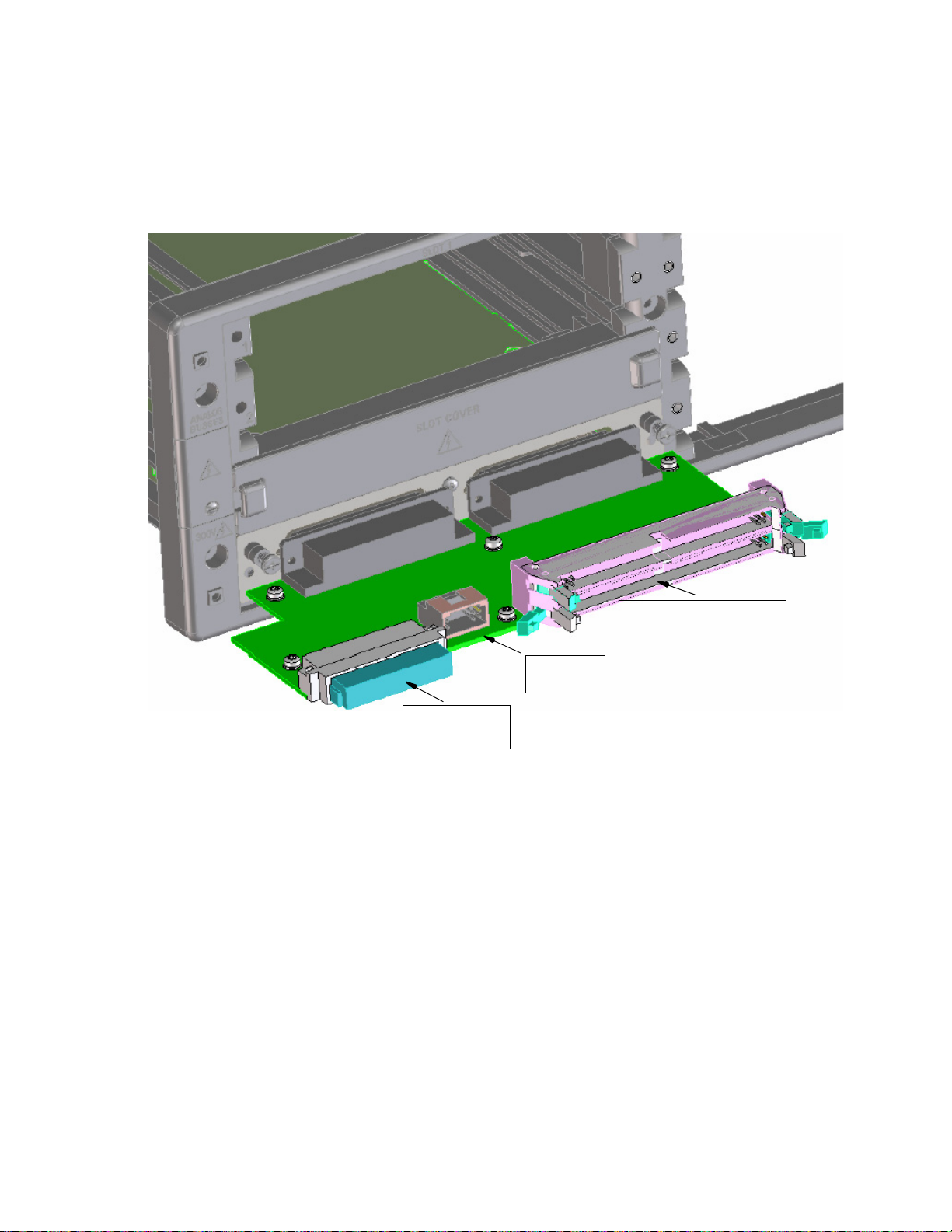
System Overview 3
A-Bus
ExpressConnect
(ICA/AUX access)
Instrument
Connector
Figure 3-9 Cut-out View of Slot 4 with Terminal Card To Create
Instument/Pin Matrix
Figure 3-9 shows the cut-out view of slot 4 when 34933A is used.
The instrument connector is to the left, the A-Bus connector in
the centre and the ICA/AUX access to the right.
TS-5020 Automotive Electronics Functional Test System Wiring Guide and Hardware Reference 3-33
Page 58
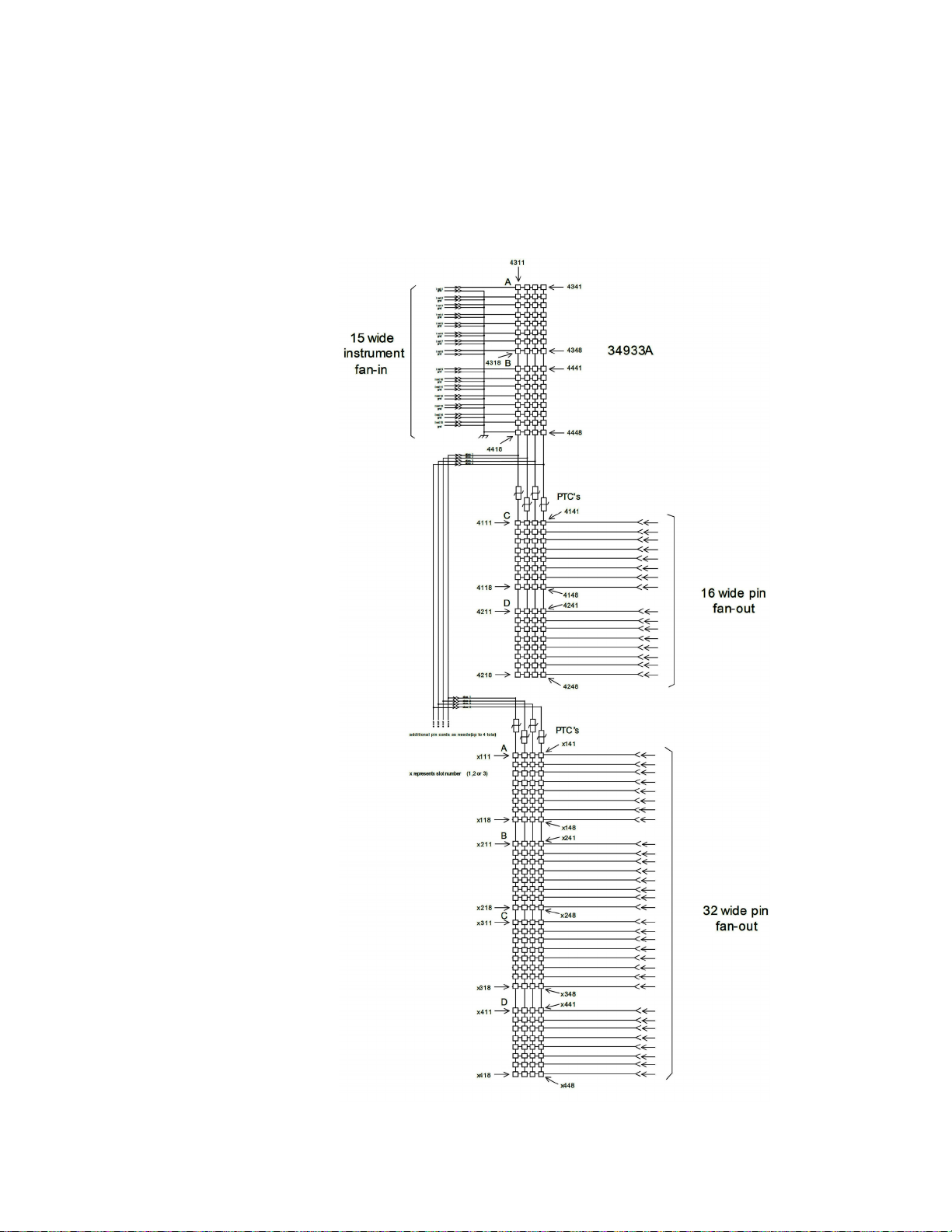
3 System Overview
Figure 3-10 Multiple 34933A configured as Instrumentation and Pin
Matrix
3-34 TS-5020 Automotive Electronics Functional Test System Wiring Guide and Hardware Reference
Page 59

System Overview 3
Figure 3-11 Multiple 34934A configured as Instrumentation and Pin
Matrix
Note that up to four matrix card can be configured to give a
maximum measurement points. Four 34933A provides
maximum 112 measurement points, where four 34934A is
capable of maximum 480 measurement points.
TS-5020 Automotive Electronics Functional Test System Wiring Guide and Hardware Reference 3-35
Page 60

3 System Overview
PC Cards
The following PCI cards are available and reside in the
Industrial PC Controller. Refer to the individual PCI card’s
documentation for more information on each card.
• Advantech PCI-1750 Digital I/O Card,
• Rocketport 8-Channel RS-232 Card,
• Softing AC2-PCI CAN Card (Automotive Serial Protocol Card),
Other PCI cards are also available for custom systems.
Keysight 53131 Universal Counter
The Keysight 53131A Universal Counter can measure
Frequency, Period, Pulse Width, Duty Cycle, Rise/Fall Time,
Time Interval, Frequency Ratio, Totalize, Phase, and Peak
Volt age .
The 53131A is capable of measuring frequencies to 225 MHz on
Channels 1 and 2. Frequency and time interval resolutions are
10 digits in one second and 500 picoseconds, respectively. The
53131A provides GPIB measuring speed of up to 200
measurements per second.
For additional information, refer to the Keysight 53131
Universal Counter Programming Guide.
Keysight 53220 Universal Counter
The Keysight 53220A Universal Counter can measure
Frequency, Period, Pulse Width, Duty Cycle, Rise/Fall Time,
Time Interval, Frequency Ration, Totalize, Phase, and Peak
Volt age .
The 53220A is capable of measuring frequencies to 350 MHz on
Channels 1 and 2. Frequency and time interval resolutions are
12 digits in one second and 100 picoseconds, respectively. The
53220A provides GPIB measuring speed of up to 200
measurement per second.
For additional information, refer to the Keysight 53220A
350MHz Universal Frequency Counter/Timer User's Guide.
3-36 TS-5020 Automotive Electronics Functional Test System Wiring Guide and Hardware Reference
Page 61

Keysight 33220 Function/Arbitrary Waveform Generator
The Keysight 33220A function / arbitrary waveform generator
uses direct digital synthesis (DDS) techniques to create stable,
low-distortion output signals. The 33220A provides easy access
to standard sine, square, ramp, triangle, and pulse waveforms
plus you can create custom waveforms using the 50 MSa/s, 14
bit, 64 K-point arbitrary waveform function.
For additional information, refer to the Keysight 33220
Function/Arbitrary Waveform Generator User’s Guide.
Power Supplies
Available power supplies are the Keysight N6700 Low-Profile
Modular Power System (MPS), the Keysight 66x3A (for example
6643A, 6653A or 6673A) power supply, a 12VDC, 2A utility
power supply and a 24VDC, 1.5A utility power supply. The
N6700 or 66x3A supply is used to power the DUT and the utility
power supplies are used for automation control such as fans,
relays, lamps and solenoids. If a LAN switch is present in the
system, the 12VDC supply will also be used to power up the
switch.
The power supplies for DUT can be wired directly to the
Express Connector TC or Macpanel ICA pins, unless if the
optional switch/load unit (E6198B or E 6218A) is present. In
this case, the power supplies are wired to the switch/load unit
power bus connectors.
System Overview 3
Keysight N6700 MPS
The Keysight N6700 MPS is a one-rack unit high,
multiple-output programmable DC power supply system. The
MPS consists of a mainframe and up to four power modules. The
MPS gives test system designers the flexibility to create a 1- to
4-channel DC power system optimized to meet specific test
requirements.
The MPS uses a switching power supply design. It has side air
vents (no top or bottom air vents) so other instruments can be
mounted directly above or below it. Each power module is
protected against over-voltage, over- current, and
over-temperature.
TS-5020 Automotive Electronics Functional Test System Wiring Guide and Hardware Reference 3-37
Page 62

3 System Overview
Channel Names
The Channel Names of the N6700 power supply modules can be
configured automatically (Auto Determine Channel Names) or
can be overridden with your own custom Channel Names.
Either of these naming options can be selected when
configuring the N6700 using the System Configuration Editor
(SCE). The SCE can be opened from the TestExec SL Tools Menu
(click Tools | System Configuration Editor) or from this icon
in the desktop
The SCE online help contains more information on how to
configure the N6700.
3-38 TS-5020 Automotive Electronics Functional Test System Wiring Guide and Hardware Reference
Page 63

4 System Interconnects
Connector Keying .... 4-2
Connectors and Tools .... 4-3
Connecting Wiring to Test Connectors TC1- TC8 .... 4-3
Crimping Wires to Contacts .... 4-4
Inserting Contacts and Assembling the Connectors .... 4-5
Connecting To The Test System Interface .... 4-6
ESD Protection Measures .... 4-7
Operator Wrist Strap ESD Connector .... 4-8
Removing A Contact .... 4-8
Test Connector Signal Definitions .... 4-9
TC1-TC2 Pinouts .... 4-11
General TC Pins Assignment .... 4-13
Express Connect PCA Connector Definition and Pin Access .... 4-15
High-Power Connector .... 4-21
System Grounding .... 4-22
Page 64

4 System Interconnects
NOTE: Shaded area represents extended portion of keys
TC2TC1 TC3 TC4
NOTE: Shaded area represents extended portion of keys.
TC2TC1 TC3 TC4
TC6TC5 TC7 TC8
System Interconnects for Express Connect Interface
Connector Keying
The TC connectors are prevented from mating into the wrong
TC terminal by their key configurations. For example,
shows the possible key configuration to prevent the possibility
of, say, connecting a TC2 mating connector to TC1.
Figure 4-1 TC1-TC4 Connector Keying
Figure 4-1
Figure 4-2 TC1-TC8 Connector Key Configuration
4-2 TS-5020 Automotive Electronics Functional Test System Wiring Guide and Hardware Reference
Page 65

Connectors and Tools
CAUTION
The specialized connectors and tools referenced in this chapter
are available from Keysight as these options/part numbers:
• Keysight E6244A Option 001--Contains two 156-pin, ITT
• Keysight E6244A Option 013--Crimp tool for Cannon
• Keysight E6244A Option 014--Extraction tool for Cannon
• Keysight E6244A Option 020--High Power Mating
• Keysight E6244A Option 024--Extraction tool for Hi Power
Standard connectors should be acquired from your local
electronic parts supplier.
System Interconnects 4
Cannon Zero-Insertion-Force mating connectors.
connector contacts.
connector contacts.
Connector Kit.
Connectors.
Connecting Wiring to Test Connectors TC1- TC8
The figures on this and the following pages show how to connect
wiring and assemble the mating connectors for Test Connectors
TC1 through TC8. Should you make a mistake,
how to remove a contact from a connector. Each Test
Connector contact is rated at 3A (continuous).
Use only the Keysight supplied connector kit with its
non-conductive handle screw. Failure to use the Keysight
supplied kit may void the warranty.
Figure 4-3 shows
TS-5020 Automotive Electronics Functional Test System Wiring Guide and Hardware Reference 4-3
Page 66

4 System Interconnects
Crimping Wires to Contacts
Figure 4-3 Crimping Wires to Contacts
4-4 TS-5020 Automotive Electronics Functional Test System Wiring Guide and Hardware Reference
Page 67

Inserting Contacts and Assembling the Connectors
Figure 4-4 Assembling TC1 to TC4
System Interconnects 4
TS-5020 Automotive Electronics Functional Test System Wiring Guide and Hardware Reference 4-5
Page 68

4 System Interconnects
Connecting To The Test System Interface
Figure 4-5 Co n n e c t in g To T he Te s t S y s te m I n t e r f a c e
4-6 TS-5020 Automotive Electronics Functional Test System Wiring Guide and Hardware Reference
Page 69

ESD Protection Measures
In geographic areas where ESD (electro-static discharge)
potential may be high (low humidity, etc.), you may need to add
a grounding strap to the center shafts of the Test Connector
mating connector assembly.
grounding strap. Positions J1 through J6 are safety ground
connections on the Test Connector.
Figure 4-6 Adding A Grounding Strap To Reduce ESD
System Interconnects 4
Figure 4-6 shows how to add the
TS-5020 Automotive Electronics Functional Test System Wiring Guide and Hardware Reference 4-7
Page 70

4 System Interconnects
ESD
GROUND
Operator Wrist Strap ESD Connector
A connector is provided on the front of the Test System
Interface for an operator ESD wrist strap connection. The
connector is wired to Safety (Earth) ground.
Figure 4-7 Wrist Strap ESD Connector
Removing A Contact
Figure 4-8 Removing A Test Connector Contact
4-8 TS-5020 Automotive Electronics Functional Test System Wiring Guide and Hardware Reference
Page 71

System Interconnects 4
NOTE
Test Connector Signal Definitions
Table 4-1 lists the signals available on Test Connector TCx.
Signal names are listed here alphabetically and are referenced
to the pinout diagrams on the following pages
Each connector in the TC1 - TC4 Pinout Diagrams has text in a small font
and a large font.The small font text is the generic signal name. The large
font text is the actual signal name and corresponds to the actual
equipment signals
Table 4-1 TCx Signal Definitions
+12 VDC, +24 VDC +12V and +24V Power Supplies--referenced to System Ground.
DI/O (Digital I/O)
Loadcard xxx Loadcard connections to one of several different loadcards. Used to switch
Pmatrix xxx Measurement matrix pin access. These lines used for low current
PS+, PS-, PS S+, PS S- Device Under Test (DUT) Power Supply minus, plus, sense plus, sense
RS232 -Tx, -Rx, -Com
SpareInst Spare instrument connections may be configured as required by the
Safety Ground This is a high current/high noise ground. It connects the instrument rack to
System Ground
Digital input/output lines. These lines provide both digital input and
digital output signals. Digitial output is low side drive capable of
sinking approximately 200mA which may be used for fixture control.
high currents.
measurement connections.
minus.
Serial connections from the Industrial PC Controller’s COM2 port. TC1
Connector.
user. These connections work well for single channel instruments.
Connection to these lines is via the "SYSTEM" or "SYSCON"
connectors in the back of the ExpressConnect PCA.
safety or earth ground. There are six Safety Ground pins per Test Connector.
Be sure to connect ALL Safety Ground lines to your UUT to ensure proper
current sharing.
Earth referenced ground. TCx Connectors.
Trigger Various triggers/clocks. Used by DAC and DMM on TC1-TC2 or
available for use on TC3 and above.
UserAccess User access lines may be configured as required by the user. These
connections work well for multi-channel instruments or serial access.
Connection to these lines is via the "CONFIG" connectors in the back
of the ExpressConnect PCA.
TS-5020 Automotive Electronics Functional Test System Wiring Guide and Hardware Reference 4-9
Page 72

4 System Interconnects
The system integrator may configure various uncommitted TC
connector pin groups for use as required for their specific
application. There are two connectors on the back of the
ExpressConnect Printed Circuit Assembly (PCA) that map to
the TC connector for this purpose:
• Spare Instrument (SpareInst) pins may be accessed
through the System connector. These pins work well for
single channel interconnect, where a simple BNC or
Banana plug connector can be used to route the signal
(see cables at end of manual). These pins are available for
use as needed on connectors TC3 and above (note that
these pins are reserved for the DAC & Serial on TC1 &
TC2). The System Connector located on the
ExpressConnect PCA and is labeled “SYSCON” on the full
sized ExpressConnect PCA or “SYSTEM” on the low
profile ExpressConnect PCA. See
Figure 4-9 to Figure 4-12
for details of the specific rows and how they map to the
TC connector.
• User Access (UserAccess) pins may be accessed through the
Configuration connector. These pins work well for
multi-channel instruments (such as digitizers or DAC channels),
or for multi-channel serial access (such as for a flash
programming station). These pins are available for use as
needed on all of the TC connectors. The Configuration
connector located on the ExpressConnect PCA and is labeled
“CONFIG”. Row32A-Row1A map in to
UserAccess1-UserAccess32 respectively.
These TC connector pins are intended for low current access
and should not be used above 500mA.
4-10 TS-5020 Automotive Electronics Functional Test System Wiring Guide and Hardware Reference
Page 73

TC1-TC2 Pinouts
A
Ch1 Ch2 Ch3 Ch1 COM Ch2 COM Ch3 COM
A
B
Ch4 Ch5 Ch6 Ch4 COM Ch5 COM Ch6 COM
B
C
Ch7 Ch8 Ch9 Ch7 COM Ch8 COM Ch9 COM
C
D
Ch10 Ch11 Ch12 Ch10 COM Ch11 COM Ch12 COM
D
E
Ch13 Ch14 Ch15 Ch13 COM Ch14 COM Ch15 COM
E
F
Ch16 Ch17 Ch18 Ch16 COM Ch17 COM Ch18 COM
F
G
Ch19 Ch20 PS S- Ch19 COM Ch20 COM PS S+
G
H
PS- PS - PS - PS+ PS+ PS+
H
J
Safety Ground Safety Ground Safety Ground Safety Ground Safety Gr ound Safety Ground
J
K
DIO0 DIO1 System Ground not used DMM Trig + System Ground
K
L
DIO2 DIO3 COM2 Gnd not used not used not used
L
M
DIO4 DIO5 COM2 Rx not used DAC Clk not used
M
N
DIO6 DIO7 COM2 Tx not used DAC Trig not used
N
P
UserAccess#1
UserAccess#2 UserAccess#3 UserAccess#4 Aux Inst #1 Aux Inst #2
P
R
UserAccess#5 UserAccess#6 UserAccess#7 UserAccess#8 System Ground System Ground
R
S
UserAccessCom UserAccessCom UserAccessCom UserAccessCom
Serial1(-)
Serial1(+)
S
T
UserAccess#9 UserAccess#10 UserAccess#11 UserAccess#12
Serial2(-)
Serial2(+)
T
U
UserAccess#13 UserAccess#14 UserAccess#15 UserAccess#16
DAC#1 Hi
DAC#1 Lo
U
V
UUT Common 1 UUT Comm on 1 UUT Common 1 UUT Common 1 PMatrix* 1 Row 1 Pmatrix* 1 Row 2
V
W
PMatrix* 1 Row 3 PMatrix* 1 Row 4 PMatrix* 1 Row 5 PMatrix* 1 Row 6 PMatrix* 1 Row 7 PMatrix* 1 Row 8
W
X
PMatrix* 1 Row 9 PMatrix* 1 Row 10 PMatrix* 1 Row 11 PMatrix* 1 Row 12 PMatrix* 1 Row 13 PMatri x* 1 Row 14
X
Y
UUT Common 1 UUT Comm on 1 UUT Common 1 UUT Common 1 UUT Comm on 1 UUT Com mon 1
Y
Z
PMatrix* 1 Row 15 PMatrix* 1 Row 16 not used* Not used Not used Not used
Z
AA
Not used Not used Not used Not used Not used Not used
AA
BB
UUT Common 1 UUT Comm on 1 UUT Common 1 UUT Common 1 UUT Comm on 1 UUT Com mon 1
BB
CC
Not used Not used Not used Not used Not used Not used
CC
TC1
System Interconnects 4
Figure 4-9 shows the pinouts for TC1 and Figure 4-10 the
pinouts for TC2.
Figure 4-11 and Figure 4-12 show the general pinout mapping
for TCn and TCn+1.
Note that TC1 pins A1 to J6 are reserved for the 20-channel, 5A
switch module in the 34980 A Multifunction Switch / Measure
unit. Refer to
Figure 3-8 for more details.
Figure 4-9 TC1 Pinouts
TC1
123 456
123 456
TS-5020 Automotive Electronics Functional Test System Wiring Guide and Hardware Reference 4-11
Page 74
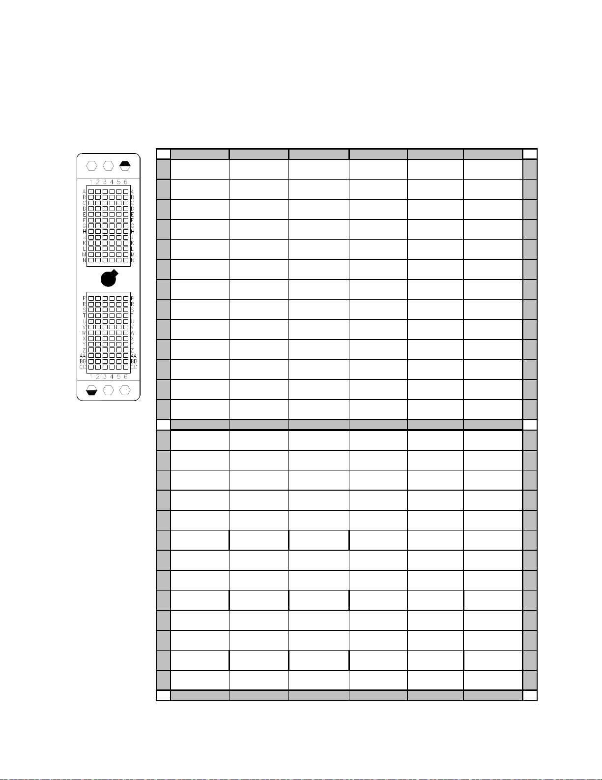
4 System Interconnects
345
6
A
Ch1 Ch2 Ch3 Ch1 COM Ch2 COM Ch3 COM
A
B
Ch4 Ch5 Ch6 Ch4 COM Ch5 COM Ch6 COM
B
C
Ch7 Ch8 Ch9 Ch7 COM Ch8 COM Ch9 COM
C
D
Ch10 Ch11 Ch12 Ch 10 COM Ch11 COM Ch1 2 COM
D
E
Ch13 Ch14 Ch15 Ch 13 COM Ch14 COM Ch1 5 COM
E
F
Ch16 Ch17 Ch18 Ch 16 COM Ch17 COM Ch1 8 COM
F
G
Ch19 Ch20 N/C Ch 19 COM Ch20 COM N/ C
G
H
N/ C N/ C N/ C N/ C N/ C N/ C
H
J
Safety Ground Safety Ground Safety Ground Safety Ground Safety Ground Safety Ground
J
K
DIO8 DIO9 System Ground Syst em Ground Syst em Ground System Ground
K
L
DIO10 DIO11 System Ground +12 VDC System Ground System Ground
L
M
DIO12 DIO13 System Ground not used System Ground not used
M
N
DIO14 DIO15 not used +24 VDC Syst em Ground not used
N
P
UserAccess#17 UserAccess#18 UserAccess#19 UserAccess#20 Aux Inst #3 Aux Inst #4
P
R
UserAccess#21 UserAccess#22 UserAccess#23 UserAccess#24 System Ground Syst em Ground
R
S
UserAccessCom UserAccessCom UserAccessCom UserAccessCom
DAC#2 Hi
DAC#2 Lo
S
T
UserAccess#25 UserAccess#26 UserAccess#27 UserAccess#28
DAC#3 Hi
DAC#3 Lo
T
U
UserAccess#29 UserAccess#30 UserAccess#31 UserAccess#32
DAC#4 Hi
DAC#4 Lo
U
V UUT Common 2 UUT Common 2 UUT Common 2 UUT Common 2
Pmatrix* 2 Row 1 Pmatrix* 2 Row 2
V
W
Pmatrix* 2 Row 3 Pmatrix* 2 Row 4 Pmatrix* 2 Row 5 Pmatrix* 2 Row 6 Pmat ri x* 2 Row 7 Pmat ri x* 2 Row 8
W
X
Pmatrix* 2 Row 9 Pmatrix* 2 Row 10 Pmatrix* 2 Row 11 Pmatrix* 2 Row 12 Pmatrix* 2 Row 13 Pmatrix* 2 Row 14
X
Y UUT Co mmon 2 UUT Commo n 2 UUT Com mon 2 UUT Common 2 UUT Common 2 UUT Common 2 Y
Z
Pmatrix* 2 Row 15 Pmatrix* 2 Row 16 Pmatrix* 2 Row 17 Pmatrix* 2 Row 18 Pmatri x* 2 Row 19 Pmatri x* 2 Row 20
Z
AA
Pmatrix* 2 Row 21 Pmatrix* 2 Row 22 Pmatrix* 2 Row 23 Pmatrix* 2 Row 24 Pmatri x* 2 Row 25 Pmatri x* 2 Row 26
AA
BB
UUT Co mmon 2 UUT Common 2 UUT Com mon 2 UUT Common 2 UUT Common 2 UUT Common 2
BB
CC
Pmatrix* 2 Row 27 Pmatrix* 2 Row 28 Pmatrix* 2 Row 29 Pmatrix* 2 Row 30 Pmatri x* 2 Row 31 Pmatri x* 2 Row 32
CC
345
6
TC2
TC2
Figure 4-10 TC2 Pinouts
12
4-12 TS-5020 Automotive Electronics Functional Test System Wiring Guide and Hardware Reference
12
Page 75

C
n
(n = 3, 5, 7)
123456
A
loadcard n.01 loadcard n.02 loadcard n.03 loadcard n.04 loadcard n.05 loadcard n.06
A
B
loadcard n.07 loadcard n.08 loadcard n.09 loadcard n.10 loadcard n.11 loadcard n.12
B
C
loadcard n.13 loadcard n.14 loadcard n.15 loadcard n.16 loadcard n.17 loadcard n.18
C
D
loadcard n.19 loadcard n.20 loadcard n.21 loadcard n.22 loadcard n.23 loadcard n.24
D
E
loadcard n.25 loadcard n.26 loadcard n.27 loadcard n.28 loadcard n.29 loadcard n.30
E
F
loadcard n.31 loadcard n.32 loadcard n.33 loadcard n.34 loadcard n.35 loadcard n.36
F
G
loadcard n.37 loadcard n.38 loadcard n.39 loadcard n.40 loadcard n.41 loadcard n.42
G
H
loadcard n.43 loadcard n.44 loadcard n.45 loadcard n.46 loadcard n.47 loadcard n.48
H
J
Safet y Ground Saf ety Ground Safet y Ground Safety Ground Safety Ground Safet y Ground
J
K
Digital I/O Digital I/O System Ground
Loadbox PB
S1
[1]
Tri gger #1 System Ground
K
L
Digital I/O Digital I/O Not Used
Loadbox PB
S2
[1]
Tri gger #2 Not Used
L
M
Digital I/O Digital I/O Not Used
Loadbox PB
S3
[1]
Tri gger #3
Loadbox I
sen1
[1]
M
N
Digital I/O Digital I/O Not Used
Loadbox PB
S4
[1]
Tri gger #4
Loadbox I
sen2
[1]
N
P
UserAccess 1 UserAccess 2 UserAccess 3 UserAccess 4 Aux Inst #1 Aux Inst #2
P
R
UserAccess 5 UserAccess 6 UserAccess 7 UserAccess 8 System Ground System Ground
R
S
UserAccess Com1 UserAccess Com1 UserAccess Com1 UserAccess Com1 InstAccess#1 [2] InstAccess#2 [2]
S
T
UserAccess 9 UserAccess 10 UserAccess 11 UserAccess 12 InstAccess#3 [2] InstAccess#4 [2]
T
U
UserAccess 13 UserAccess 14 UserAccess 15 UserAccess 16 ARB Hi gh [2] ARB Low [2]
U
V
UUT Common n UUT Common n UUT Common n UUT Common n PMatri x n Row 1 PMatrix n Row 2
V
W
PMatrix n Row 3 PMatrix n Row 4 PMatrix n Row 5 PMatrix n Row 6 PMatrix n Row 7 PMatrix n Row 8
W
X
PMatrix n Row 9 PMatrix n Row 10 PMatrix n Row 11 PMatrix n Row 12 PMatri x n Row 13 PMatri x n Row 14
X
Y
UUT Common n UUT Common n UUT Common n UUT Common n UUT Common n UUT Common n
Y
Z
PMatri x n Row 15 PMatrix n Row 16 PMatri x n Row 17 PMatri x n Row 18 PMatrix n Row 19 PMatrix n Row 20
Z
AA
PMatrix n Row 21 PMatrix n Row 22 PMatrix n Row 23 PMatrix n Row 24 PMatri x n Row 25 PMatri x n Row 26
AA
BB
UUT Common n UUT Common n UUT Common n UUT Common n UUT Common n UUT Common n
BB
CC
PMatri x n Row 27 PMatrix n Row 28 PMatri x n Row 29 PMatri x n Row 30 PMatrix n Row 31 PMatrix n Row 32
CC
123456
T
System Interconnects 4
General TC Pins Assignment
The connections on the TC pins depend on the components that
the user has ordered for the system.
Figure 4-11 TCn Pin Assignments
TS-5020 Automotive Electronics Functional Test System Wiring Guide and Hardware Reference 4-13
Notes:
[1] Power Bus Sense and I Sense are present only on TC3 and
[2] Spare instrument access pins.
only if the loadbox is present. Otherwise the pins are not
used.
Page 76

4 System Interconnects
n+1
123456
A
loadcard n+1.01 l oadcard n+1.02 loadcard n+1. 03 loadcard n+1.04 loadcard n+1.05 loadcar d n+1.06
A
B
loadcard n+1.07 l oadcard n+1.08 loadcard n+1. 09 loadcard n+1.10 loadcard n+1.11 loadcar d n+1.12
B
C
loadcard n+1.13 l oadcard n+1.14 loadcard n+1. 15 loadcard n+1.16 loadcard n+1.17 loadcar d n+1.18
C
D
loadcard n+1.19 l oadcard n+1.20 loadcard n+1. 21 loadcard n+1.22 loadcard n+1.23 loadcar d n+1.24
D
E
loadcard n+1.25 l oadcard n+1.26 loadcard n+1. 27 loadcard n+1.28 loadcard n+1.29 loadcar d n+1.30
E
F
loadcard n+1.31 l oadcard n+1.32 loadcard n+1. 33 loadcard n+1.34 loadcard n+1.35 loadcar d n+1.36
F
G
loadcard n+1.37 l oadcard n+1.38 loadcard n+1. 39 loadcard n+1.40 loadcard n+1.41 loadcar d n+1.42
G
H
loadcard n+1.43 l oadcard n+1.44 loadcard n+1. 45 loadcard n+1.46 loadcard n+1.47 loadcar d n+1.48
H
J
Safet y Ground Saf ety Ground Safety Ground Safety Ground Safet y Ground Saf ety Ground
J
K
Digital I/O Digital I/O System Ground Safety Ground Safety Ground System Ground
K
L
Digital I/O Digital I/O Safety Ground Utility supply Safet y Ground Syst em Ground
L
M
Digital I/O Digital I/O Safety Ground Utility supply Safet y Ground Not used
M
N
Digital I/O Digital I/O Not used Utility supply Saf ety Ground Not used
N
P
UserAccess 17 UserAccess 18 UserAccess 19 UserAccess 20 Aux Inst #3 Aux Inst #4
P
R
UserAccess 21 UserAccess 22 UserAccess 23 UserAccess 24 System Ground System Ground
R
S
User Acces s Com1 User Access Com1 User Access Com2 Use rAcc ess Com2 I nstAccess#5 [3] InstAccess#6 [3]
S
T
UserAccess 25 UserAccess 26 UserAccess 27 UserAccess 28 InstAccess#7 [3] InstAccess#8 [3]
T
U
UserAccess 29 UserAccess 30 UserAccess 31 UserAccess 32 InstAccess#9 [3] InstAccess#10 [3]
U
V UUT Common n+1 UUT Common n+1 UUT Common n+1 UUT Common n+1 PMatri x n+1 Row 1 PMatrix n+1 Row 2 V
W
PMatrix n+1 Row 3 PMatri x n+1 Row 4 PMatri x n+1 Row 5 PMatrix n+1 Row 6 PMatrix n+1 Row 7 PMatrix n+1 Row 8
W
X PMatrix n+1 Row 9 PMatrix n+1 Row 10 PMatrix n+1 Row 11 PMatrix n+1 Row 12 PMatrix n+1 Row 13 PMatrix n+1 Row 14 X
Y
UUT Common n+1 UUT Common n+1 UUT Common n+1 UUT Common n+1 UUT Common n+1 UUT Common n+1
Y
Z PMatrix n+1 Row 15 PMatrix n+1 Row 16 PMatrix n+1 Row 17 PMatrix n+1 Row 18 PMatrix n+1 Row 19 PMatrix n+1 Row 20 Z
AA PMatrix n+1 Row 21 PMatrix n+1 Row 22 PMatrix n+1 Row 23 PMatrix n+1 Row 24 PMatrix n+1 Row 25 PMatrix n+1 Row 26 AA
BB
UUT Common n+1 UUT Common n+1 UUT Common n+1 UUT Common n+1 UUT Common n+1 UUT Common n+1
BB
CC PMatrix n+1 Row 27 PMatrix n+1 Row 28 PMatrix n+1 Row 29 PMatrix n+1 Row 30 PMatrix n+1 Row 31 PMatrix n+1 Row 32 CC
123456
Figure 4-12 TC
(n = 3, 5, 7)
TC
Pin Assignments
n+1
4-14 TS-5020 Automotive Electronics Functional Test System Wiring Guide and Hardware Reference
Note:
[3] In TC4, spare InstAccess is used for E6198A Switch Load
Unit (SLU) DAC if it is present.
Page 77
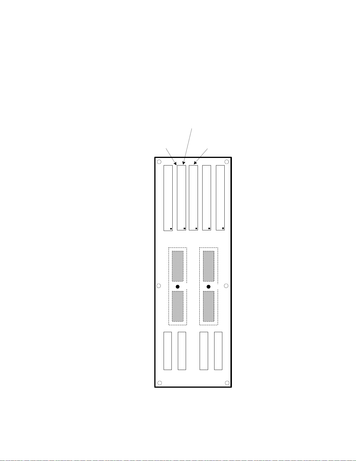
Load Card 1
J10
J3
J4
System Connector
J6
Configuration connector
J7
Resource Connector
J8
PIN Card 1 Connector
J5
PIN Card 2 Connector
J9
Load Card 1
Load Card 2
Load Card 2
J11 J12 J13
"PINCARD2"
"PINCARD1"
"LOADBOX"
"CONFIG"
"SYSCONN"
"Meritec style" connector
Row 1 starts on THIS end
AABB
TC1
TC2
System Connector routes to "InstAccess" and
"Trigger" areas of TC1 & TC2 and allows user to
bring resources to TC connectors as needed
Configuration Connector routes to
"UserAaccess" areas of TC1 & TC2 and allows
user to bring resources to TC connectors as
needed
Express Connect PCA Connector Definition and Pin Access
Users may access the sockets using the appropriate
E3750-61603/04 and E3750-61621cables as needed.
Figure 4-13 PCA Layout For Full Profile Express Connect (For TC1-TC8
Use)
System Interconnects 4
TS-5020 Automotive Electronics Functional Test System Wiring Guide and Hardware Reference 4-15
Page 78
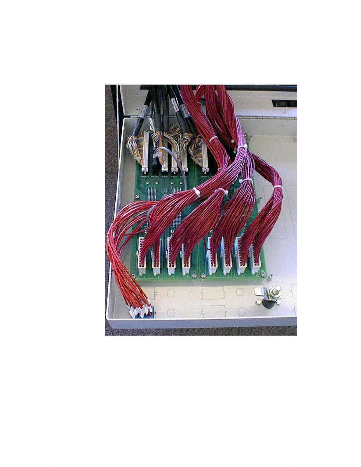
4 System Interconnects
Figure 4-14 View of Full Profile Express Connect PC Assembly (2 of 4
possible PC Assembly shown)
4-16 TS-5020 Automotive Electronics Functional Test System Wiring Guide and Hardware Reference
Page 79
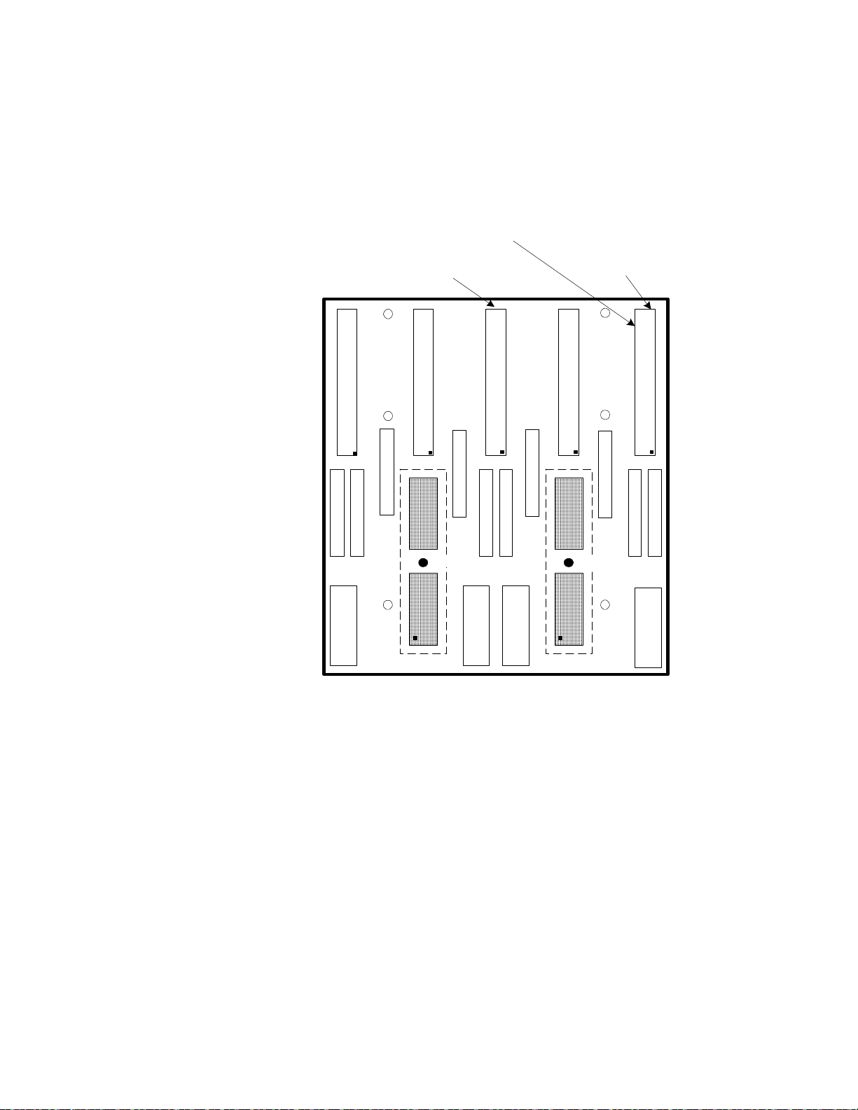
System Interconnects 4
J10 Load Card 1
A
J13 Load Card 2
B
J30 PIN Card 1 Connector
J40 Configuration Connector
J62 Sys Conn
J60 System Connector
J50 PIN Card 2 Connector
J12 Load Card 2
A
J11 Load Card 1
B
J2J1
J20 Resource Connector
J61 Sys Conn
J52 PinCd2 Conn
J51 PinCd2 Conn
J32 PinCd1 Conn
J31 PinCd1 Conn
J42 ConfigCd Conn
J41 ConfigCd Conn
J22 Resource
J21 Resource
TC1
TC2
"Meritec style" connector
Row 1 starts on THIS end
System Connector routes to "InstAccess" and
"Trigger" areas of TC1 & TC2 and allows user
to bring resources to TC connectors as needed
Configuration Connector routes to
"UserAaccess" areas of TC1 & TC2 and allow s
user to bring resources to TC connectors as
needed
Figure 4-15 PCA Layout For Low Profile Express Connect (For TC1-TC4
Use)
TS-5020 Automotive Electronics Functional Test System Wiring Guide and Hardware Reference 4-17
Page 80

4 System Interconnects
19 20191817161514131211108765432 2928272625242322 3221 3130
System Ground
TS-5020 System
Connector (Syscon)
DAC #2
Serial2
Serial1
DAC #4
DAC #3
Top View
DMM Trig+
DAC Clk
DAC Trig
TC1, TC2 Connections
RS-232 TX
DAC #1
RS-232 Common
RS-232 RX
Figure 4-16 TS-5020 System Connector (J6 or J60) TC1 and TC2
Assignments
4-18 TS-5020 Automotive Electronics Functional Test System Wiring Guide and Hardware Reference
Page 81

19 20191817161514131211108765432 2928272625242322 3221 3130
System Ground
TS-5020 System
Connector (Syscon)
Spare Inst. #1
Spare Inst. #7
Spare Inst. #6
Spare Inst. #5
Spare Inst. #4
Spare Inst. #3
Spare Inst. #2
DAC Common or Spare Inst. #10
DAC Channel 1 or Spare Inst.
#9
DAC Channel 1 or Spare Inst. #8
Top View
Not Used (Trigger #1)
[1]
Not Used (Trigger #2)
[1]
Not Used (Trigger #3)
[1]
Not Used (Trigger #4)
[1]
Not Used
Not Used
Not Used
Not Used
Not Used (ARB Low)
[1]
Not Used (ARB High)
[1]
Not Used (Aux #4)
[2]
Not Used (Aux #3)
[2]
Not Used (Aux #2)
[1]
Not Used (Aux #1)
[1]
System Interconnects 4
Figure 4-17 TS-5020 System Connector (J6 or J60) TCn Assignments
Notes:
[1] Available for user’s configuration. Refer to Figure 4-11 for
TC pins mapping.
[2] Refer to Figure 4-12 for TC pins mapping.
TS-5020 Automotive Electronics Functional Test System Wiring Guide and Hardware Reference 4-19
Page 82

4 System Interconnects
Figure 4-18 TS-5020 Configuration Connector (J7 or J40)
4-20 TS-5020 Automotive Electronics Functional Test System Wiring Guide and Hardware Reference
Page 83

High-Power Connector
WARNING
A high-power (HP) connector can be added to the Test System
Interface. The 16-pin HP connector can route higher current
lines to the UUT. This is ideal for powering high-current devices
or for customizing the system for applications that require
higher power.
Connections to the High Power connectors are made using a
Positronic Industries PLC18F connector. Refer to Chapter 3 for
details on using this connector with the Keysight E6178B Heavy
Duty Load Card. A kit of parts, available from Keysight (E6244A
Opt. 020), provides the following:
• 20 Male contacts (Keysight 1252-8236) for shield-mounted
• 20 Female Contacts (Keysight 1252-8235) for Keysight
System Interconnects 4
connector
1252-8234 connector housing
• Mating female connector housing (Keysight 1252-8234)
Do not exceed 60 VDC, 42VAC peak, or 30VAC rms or a maximum
15A on any pin of an HP connector.
Figure 4-19 Connecting to High Power (HP) Connector
TS-5020 Automotive Electronics Functional Test System Wiring Guide and Hardware Reference 4-21
Page 84
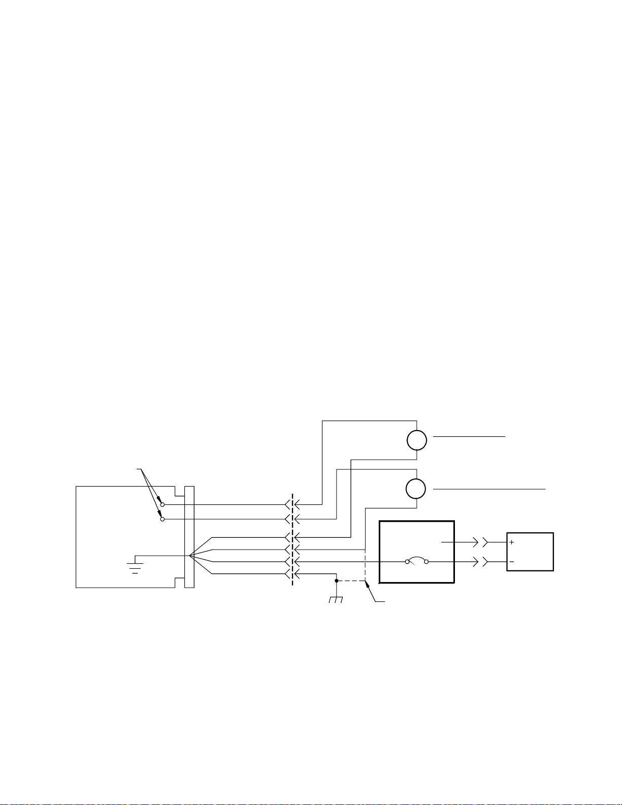
4 System Interconnects
Measurement
Te st Po i nt s
UUT
Te st
Fixture
Unit Under test
(UUT)
UUT
Ground
UUT Com
System Ground
Power Ground
Safety Ground
TC1/TC2
Connector
Safety
(Earth) Ground
Channel Shorted
PB2
PB1
UUT
Power
Supply
Connection between system and
Safety Ground is made by Mass
Interconnect and Instrument
Earth Referenced Instrument
i.e. Event Detector
Floating Instrument
High Accuracy Signal
Measurements i.e. DMM
Load Card
M
M
System Grounding
The Keysight TS-5020 Test System has these grounds:
• System Ground:
• Earth referenced ground used by customer-supplied earth
referenced instruments.
• Power Supply Grounds:
• Floating ground from the UUT Power Supplies.
• Safety or Earth (Earthed) Ground:
• This is typically a high current/high noise ground. It
connects the instrument rack to safety or earth ground
(see below).
Keysight recommends that you connect all grounds together at
the UUT (forming a star pattern).
Figure 4-20 Recommended System Grounding
4-22 TS-5020 Automotive Electronics Functional Test System Wiring Guide and Hardware Reference
Page 85

System Interconnect for Mac Panel Interface
L2000 (TITAN) Connectors and Tools
System Interconnects 4
Description Manufacturer Manufacturer Part
Crimp Frame bor both 5 Amp contacts
(0884012R-01 & 0883012-02) and 10 Amp
contacts (0884013R-01 & 0883013-02)
Positioner for 5 Amp (0884012R-01) and 10
Amp (0884013R-01) receiver contacts
Positioner for 5 Amp (0883012-02) and 10 Amp
(0883013-02) ITA contacts
Extraction Tool for 5 Amp (0884012R-01 &
0883012-02) and 10 Amp contacts
((0884013R-01 & 0883013-02)
Extraction Tool for 50 Amp contact (0884011-
01 & 0883011-02)
Crimp Frame for 3 Ghz contacts (7865100 &
7865200)
Hex die for 3 Ghz coax contact (7865100 &
7865200)
Extraction tool for 3Ghz ((7865100 & 7865200)
and 26 Ghz coax contact (7865200- 05 &
7865200-05)
Documents
Number
MAC PANEL 452400 www.macpanel.com
MAC PANEL 452202 www.macpanel.com
MAC PANEL 452401 www.macpanel.com
MAC PANEL 412604 www.macpanel.com
MAC PANEL 412615 www.macpanel.com
MAC PANEL 452300 www.macpanel.com
MAC PANEL 452303 www.macpanel.com
MAC PANEL 412615 www.macpanel.com
TS-5020 Automotive Electronics Functional Test System Wiring Guide and Hardware Reference 4-23
Page 86

4 System Interconnects
Extraction Tool, Hi-Density Pin
412604
Technical Information
Body
Spring, Plunger, Tip
Fits Following Contacts Revceiver
Aluminum Alloy
Spring, Plunger, Tip: Stainless Steel
0884027-02
Fits Following Contacts Revceiver
0884027-03
4-24 TS-5020 Automotive Electronics Functional Test System Wiring Guide and Hardware Reference
Page 87
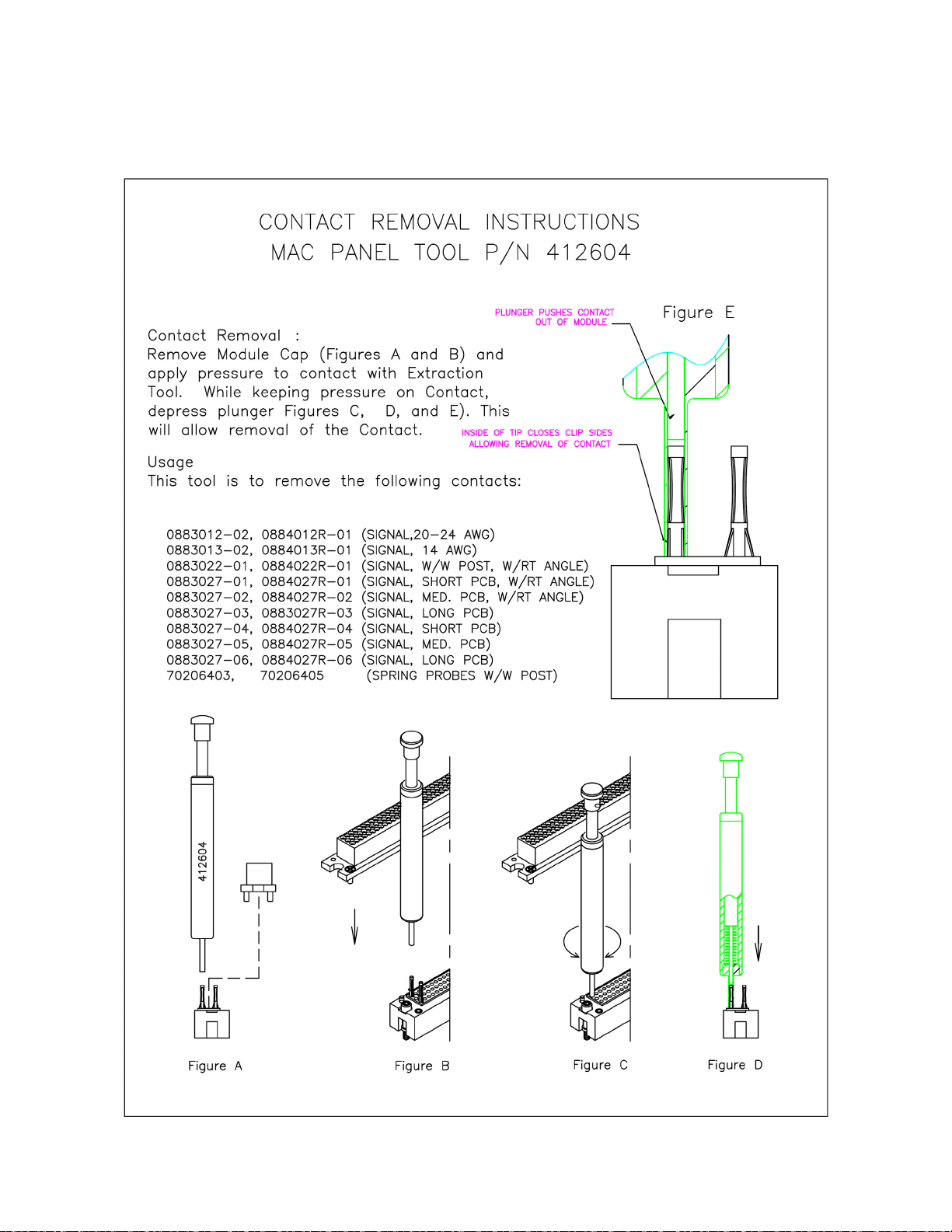
System Interconnects 4
TS-5020 Automotive Electronics Functional Test System Wiring Guide and Hardware Reference 4-25
Page 88
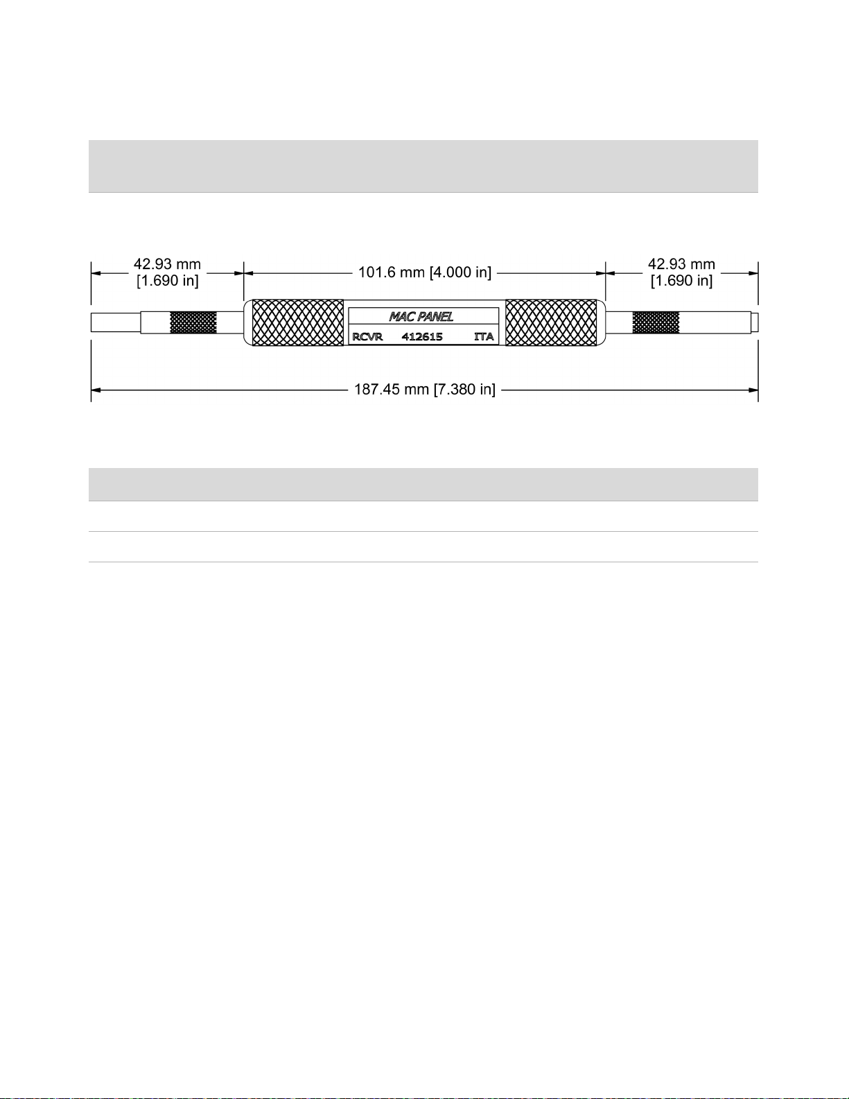
4 System Interconnects
Extraction Tool, CASS
412615
Technical Information
Body
Spring, Plunger, Screw
Aluminum Alloy
Stainless Steel
4-26 TS-5020 Automotive Electronics Functional Test System Wiring Guide and Hardware Reference
Page 89

System Interconnects 4
TS-5020 Automotive Electronics Functional Test System Wiring Guide and Hardware Reference 4-27
Page 90

4 System Interconnects
THIS PAGE IS INTENTIONALLY LEFT BLANK
4-28 TS-5020 Automotive Electronics Functional Test System Wiring Guide and Hardware Reference
Page 91

5 Test System Interface Cables
This chapter shows the construction and pinouts of the system cables
that connect to the Test System Interface.
U8970-61702 Dual Banana Metric Cable for GPIB/LXI DMM .... 5-3
U8970-61701 Cable BNC Coax to 3x1 (Non-Isolated) .... 5-3
U8970-61700 Cable Isolated Instrument BNC .... 5-3
Cables For Express Connect Interface .... 5-4
E6170-61623 Twinax DMM To Inst Matrix Cable .... 5-4
E6170-61626 DIO And Utility Power Supply To ICA Cable .... 5-4
E6170-61627 DMM Trig 34980 To ICA .... 5-6
E6170-61628 DAC 34951 To ICA Cable .... 5-6
E6170-61629 GP Relay 34938A And Power Supply To ICA Cable .... 5-8
E6170-61620 General Purpose 96-96 DINC Cable .... 5-10
E6170-61621 48 Channel Load Card Express Connect Cable .... 5-10
E6170-61630 CAN PCI To ICA Cable .... 5-11
E6170-61605 Cable for 8-CH/16-CH/24-CH Load Card to Express Connect
.... 5-12
E6230-61603 Cable for 8-CH Heavy Duty Load Card to Express Connect ....
5-13
Cables For L2000 (TITAN) Interface .... 5-14
E6218-61601 Cable, One Matrix (34933A) to L2000 (TITAN) .... 5-14
E6218-61614 CABLE, E6175A TO L2000 (TITAN) .... 5-15
E6218-61615 CABLE, E6176A TO L2000 (TITAN) .... 5-15
E6218-61620 CABLE, N9379A TO L2000 (TITAN) .... 5-16
E6218-61621 CABLE, 34951-DAC TO L2000 (TITAN) .... 5-17
E6218-61622 CABLE, 34980-DMM (TRIG) TO L2000 (TITAN) .... 5-17
E6218-61624 CABLE, E6178B TO L2000 (TITAN) .... 5-18
E6218-61625 CABLE, ONE U7177A TO L2000 (TITAN) .... 5-19
E6218-61627 CABLE, DIO TO L2000 (TITAN) .... 5-20
E6218-61628 CABLE, PS TO L2000 (TITAN) (MED CURRENT) .... 5-20
E6218-61629 CABLE, 34938 TO L2000 (TITAN) .... 5-21
E6218-61630 CABLE, CAN TO L2000 (TITAN) .... 5-21
E2240-61621 Cable, 34934A to ICA (TITAN) .... 5-22
Page 92

5 Test System Interface Cables
E2240-61622 Cable, 34939A to ICA (TITAN) .... 5-23
E2240-61623 Cable, Electronic Load to ICA (TITAN) .... 5-24
E2240-61626 Cable, System Resources E6198B and PCI DIO 1750 .... 5-25
E6218-61619 Cable, System Resources To L2000 (TITAN) .... 5-26
E6218-61626 CABLE, Dual 24-CH Load Card To L2000 (TITAN) .... 5-27
5-2 TS-5020 Automotive Electronics Functional Test System Wiring Guide and Hardware Reference
Page 93
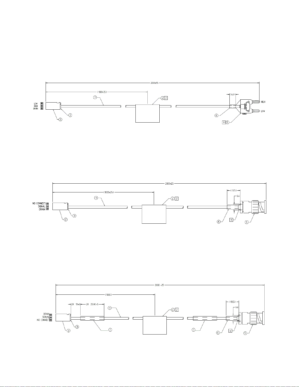
U8970-61702 Dual Banana Metric Cable for GPIB/LXI DMM
Figure 5-1 U8970-61702 (Dual Banana Metric Cable)
U8970-61701 Cable BNC Coax to 3x1 (Non-Isolated)
Figure 5-2 U8970-61701 (Cable BNC Coax to 3x1)
Test System Interface Cables 5
U8970-61700 Cable Isolated Instrument BNC
Figure 5-3 U8970-61700 (Cable Isolated Instrument BNC)
TS-5020 Automotive Electronics Functional Test System Wiring Guide and Hardware Reference 5-3
Page 94
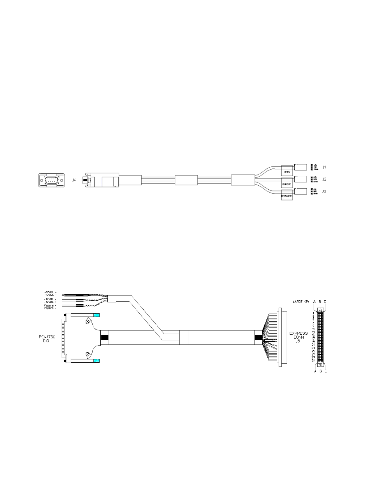
5 Test System Interface Cables
Cables For Express Connect Interface
The following section shows the construction and pinouts of the system
cables for express connect interface.
E6170-61623 Twinax DMM To Inst Matrix Cable
Figure 5-4 E6170-61623 Twinax DMM To Inst Matrix Cable
E6170-61626 DIO And Utility Power Supply To ICA Cable
Figure 5-5 E6170-61626 DIO And Utility Power Supply To ICA Cable
5-4 TS-5020 Automotive Electronics Functional Test System Wiring Guide and Hardware Reference
Page 95

Test System Interface Cables 5
61626 PCI-1750 DI O DSUB-37M 1252-3536
Express
Conn; J8
2200
DIO0 11*
1569-20WHT
a7
DIO1 30*
1569-20WHT
c7
DIO2 12*
1569-20WHT
a8
DIO3 31*
1569-20WHT
c8
DIO4 13*
1569-20WHT
a9
DIO5 32*
1569-20WHT
c9
DIO6 14*
1569-20WHT
a10
DIO7 33*
1569-20WHT
c10
DIO8 15*
1569-20WHT
a21
DIO9 34*
1569-20WHT
c21
DIO10 16*
1569-20WHT
a22
DIO11 35*
1569-20WHT
c22
DIO12 17*
1569-20WHT
a23
DIO13 36*
1569-20WHT
c23
DIO14 18*
1569-20WHT
a24
DIO15 37*
1569-20WHT
c24
Jumper (11) to 1*
1569-20WHT
a/r
Jumper (30) to 20*
1569-20WHT
a/r
Jumper (12) to 2*
1569-20WHT
a/r
Jumper (31) to 21*
1569-20WHT
a/r
Jumper (13) to 3*
1569-20WHT
a/r
Jumper (32) to 22*
1569-20WHT
a/r
Jumper (14) to 4*
1569-20WHT
a/r
Jumper (33) to 23*
1569-20WHT
a/r
Jumper (15) to 5*
1569-20WHT
a/r
Jumper (34) to 24*
1569-20WHT
a/r
Jumper (16) to 6*
1569-20WHT
a/r
Jumper (35) to 25*
1569-20WHT
a/r
Jumper (17) to 7*
1569-20WHT
a/r
Jumper (36) to 26*
1569-20WHT
a/r
Jumper (18) to 8*
1569-20WHT
a/r
Jumper (37) to 27*
1569-20WHT
a/r
DIO IGND 9
1569-20BLK
a1
28
1569-20BLK
c1
29
1569-20BLK
c6
Tinned wire (twist together)
+12V
+12VDC; +
strip 10mm, twist & tin*
1569-20RED
a25
(strip 10mm, twi(st & tin)
1569-20RED
c25
(strip 10mm, twi(st & tin)
1569-20RED
a26
+12VRTN
+12VDC; -
strip 10mm, twist & tin*
1569-20BLK
a29
(strip 10mm, twi(st & tin)
1569-20BLK
c29
(strip 10mm, twi(st & tin)
1569-20BLK
a28
(twist together)
-12V
-12VDC; -
strip 10m m & trim
1569-20BLK
a27
-12VRTN
-12VDC; +
strip 10m m & trim
1569-20RED
c28*
(twist together)
SpareV
Vspare;+
strip 10m m & trim
1569-20RED
c27
SpareVRTN
Vspare;-
strip 10m m & trim
1569-20BLK
(c28)
Table 5-1 E6170-61626 Cable Pinout Table
Signal Part #Product; Port Connector Cable Connector Product; Port Length
Name E6170- Label) Position Wire Positi on Label) mm)
TS-5020 Automotive Electronics Functional Test System Wiring Guide and Hardware Reference 5-5
Page 96
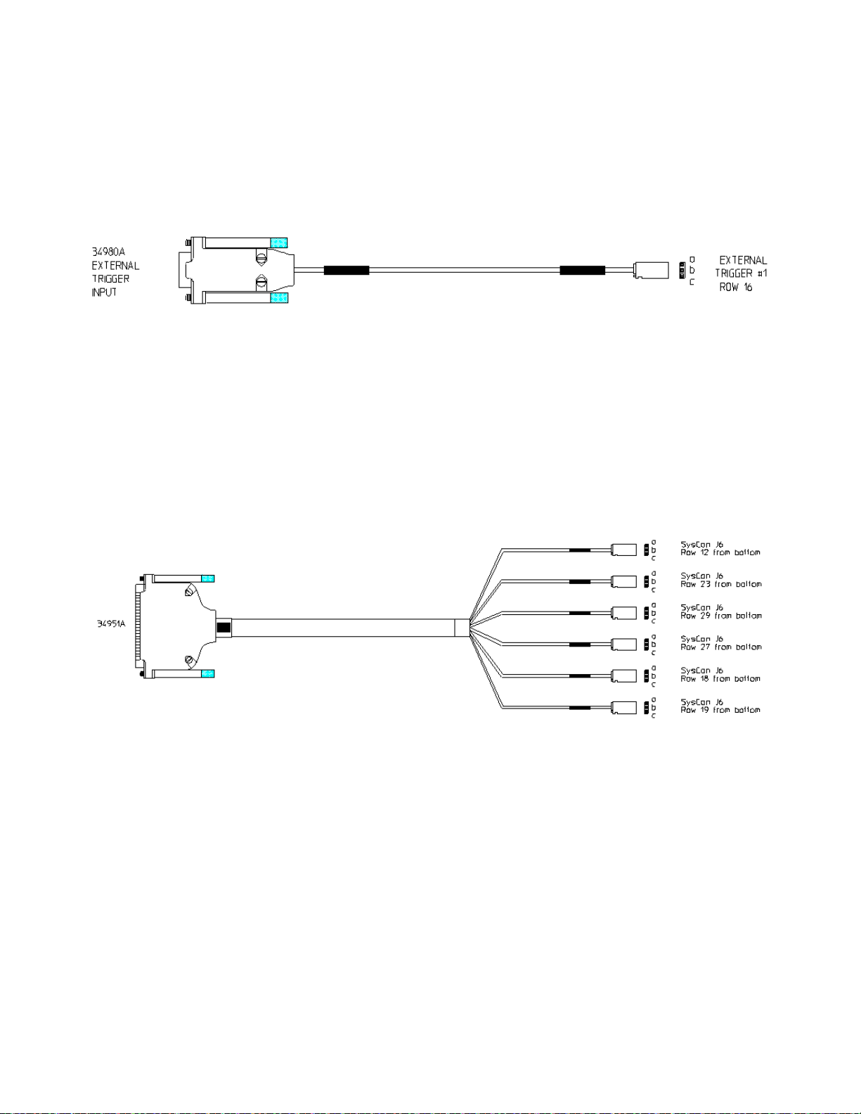
5 Test System Interface Cables
E6170-61627 DMM Trig 34980 To ICA
Figure 5-6 E6170-61627 DMM Trig 34980 To ICA
E6170-61628 DAC 34951 To ICA Cable
Figure 5-7 E6170-61628 DAC 34951 To ICA Cable
5-6 TS-5020 Automotive Electronics Functional Test System Wiring Guide and Hardware Reference
Page 97

Table 5-2 E6170-61628 Cable Pinout Table
Test System Interface Cables 5
TS-5020 Automotive Electronics Functional Test System Wiring Guide and Hardware Reference 5-7
Page 98

5 Test System Interface Cables
E6170-61629 GP Relay 34938A And Power Supply To ICA Cable
Figure 5-8 E6170-61629 Cable
5-8 TS-5020 Automotive Electronics Functional Test System Wiring Guide and Hardware Reference
Page 99

Table 5-3 E6170-61629 Cable Pinout Table
Signal Part # Product; Port Connector Cable Connector Product; Port Length
Name E6170- Label Posi tion Wire Posi tion L abel (mm)
61629
34938A Bank 1 DSUB-50F (1 of 2)
Molex 39- 01-2245 (2
total)
1000
Ch1 3 1569-20WHT LoadcardA.12 LOADCARD A
Ch1.Com 4 1569-20WHT Loadc ardB.24 LOADCARD B
Ch2 7
1569-20WHT
LoadcardA.11
Ch2.Com 8 1569-20WHT Loadc ardB.23
Ch3 9 1569-20WHT LoadcardA.10
Ch3.Com 10
1569-20WHT
LoadcardB.22
Ch4 13
1569-20WHT
LoadcardA.9
Ch4.Com 14 1569- 20WHT LoadcardB. 21
Ch5 15 1569- 20WHT Loadcar dA.8
Ch5.Com 16
1569-20WHT
LoadcardB.20
Ch6 1 1569-20WHT LoadcardA.7
Ch6.Com 2 1569-20WHT Loadc ardB.19
Ch7 5
1569-20WHT
LoadcardA.6
Ch7.Com 6
1569-20WHT
LoadcardB.18
Ch8 39 1569- 20WHT Loadcar dA.5
Ch8.Com 40 1569- 20WHT LoadcardB. 17
Ch9 11
1569-20WHT
LoadcardA.4
Ch9.Com 12 1569- 20WHT LoadcardB. 16
Ch10 47 1569-20WHT LoadcardA. 3
Ch10.Com 48
1569-20WHT
LoadcardB.15
34938A Bank 2 DSUB-50F (2 of 2)
Ch11 3
1569-20WHT
LoadcardA.2
Ch11.Com 4
1569-20WHT
LoadcardB.14
Ch12 7 1569-20WHT Loadc ardA.1
Ch12.Com 8 1569-20WHT Loadc ardB.13
Ch13 9
1569-20WHT
LoadcardA.13
Ch13.Com 10 1569-20WHT LoadcardB.1
Ch14 13 1569-20WHT LoadcardA. 14
Ch14.Com 14
1569-20WHT
LoadcardB.2
Ch15 15
1569-20WHT
LoadcardA.15
Ch15.Com 16 1569-20WHT LoadcardB.3
Ch16 1 1569-20WHT Loadc ardA.16
Ch16.Com 2
1569-20WHT
LoadcardB.4
Ch17 5 1569-20WHT Loadc ardA.17
Ch17.Com 6 1569-20WHT Loadc ardB.5
Ch18 39
1569-20WHT
LoadcardA.18
Ch18.Com 40
1569-20WHT
LoadcardB.6
Ch19 11 1569-20WHT LoadcardA. 19
Ch19.Com 12 1569-20WHT LoadcardB.7
Ch20 47
1569-20WHT
LoadcardA.20
Ch20.Com 48 1569-20WHT LoadcardB.8
(twist together)
PS+ PS; + AMP-321233* 1569- 20RED LoadcardB.10 2000
(AMP-321233) 1569-20RED LoadcardB.11
(AMP-321233)
1569-20RED
LoadcardB.12
PS-
PS; -
AMP-321233*
1569-20BLK
LoadcardA.22
(AMP-321233) 1569-20BLK LoadcardA.23
(AMP-321233) 1569-20BLK LoadcardA.24
(twist together)
PSSense+ PS; Sense+ (strip 10mm & t in) 1569- 20RED LoadcardB.9
PSSense-
PS; Sense-
(strip 10mm & tin)
1569-20BLK
LoadcardA.21
Test System Interface Cables 5
TS-5020 Automotive Electronics Functional Test System Wiring Guide and Hardware Reference 5-9
Page 100

5 Test System Interface Cables
E6170-61620 General Purpose 96-96 DINC Cable
Figure 5-9 E6170-61620 General Purpose 96-96 DINC Cable
E6170-61621 48 Channel Load Card Express Connect Cable
Figure 5-10 E6170-61621 48 Channel Load Card Express Connect Cable
5-10 TS-5020 Automotive Electronics Functional Test System Wiring Guide and Hardware Reference
 Loading...