

Page 1

Operating and
Service Guide
Keysight Truevolt Series
Digital Multimeters
Page 2

Notice: This document contains referencesto Agilent Tech-
nologies. Agilent's former Test and Measurement business
has become Keysight Technologies. For more information,
go to www.keysight.com.
Page 3

Safety and Regulatory Information 11
Notices 11
Manual Information 11
Software Revision 11
Warranty 11
Technology Licenses 11
Restricted Rights Legend 12
Safety Notices 13
Safety Symbols 13
Safety Information 14
General 14
Measurement Limits 16
Input Terminal Measurement Limits 18
Sense Terminal Measurement Limits 18
IEC Measurement Category II 19
Keysight 34138A Test Lead Set 19
Test Lead Ratings 19
Operation 19
Maintenance 19
Declaration of Conformity 20
Welcome 21
Introductory Information 21
User Information 21
SCPI Programming Reference 22
Service and Repair 22
Performance Verification 22
Calibration Procedures 22
Introduction to the Instrument 23
Instrument at a Glance 23
Display – Easily display, save and document your measurement results 23
Measurements – Keysight’s Truevolt measurement performance with modern I/O accessibility 23
Programming Language 23
Front Panel at a Glance 24
Front Panel Keys 24
Rear Panel at a Glance 25
Models and Options 26
Options Installed at Factory 26
Options Installed by Distributor or End Customer 26
Remote Interface Configuration 27
Connectivity Software 27
GPIB Configuration 27
LAN Configuration 28
Web Interface 31
LAN Configuration Procedure 32
More about IP Addresses and Dot Notation 33
Firmware Update 34
Contacting Keysight Technologies 35
Quick Start 36
Prepare Instrument for Use 36
Setting the AC Mains Line Voltage Selector and Fuse Installation 37
Connect Power and I/O Cables 39
4
Keysight TruevoltSeries Operating and Service Guide
Page 4

Adjust the Carrying Handle 40
Use Built-in Help System 41
View the help information for a front panel key 41
View the list of help topics and use interactive demos 42
View the list of recent instrument errors. 43
View the help information for displayed messages. 43
Rack Mount the Instrument 44
Removing the Handle and Bumpers 44
Rack Mounting a Single Instrument 44
Rack Mounting Instruments Side-by-Side 44
Sliding Support Shelf 45
Features and Functions 46
Continuous, Data Log, and Digitize Modes 47
Continuous Mode 47
Data Log Mode 47
Digitize Mode 47
Data Log and Digitize Mode Default Settings 48
Additional Data Log Default Settings 48
Additional Digitize Default Settings 49
Front Panel Menu Reference 50
[Acquire] key 54
[Math] key 54
[Display] key 54
[Utility] key 55
Measurements 56
DC Voltage 57
AC Voltage 60
DC Current 62
AC Current 64
Resistance 66
Temperature (34460A and 34461A) 69
Temperature (34465A and 34470A) 71
Capacitance 76
Continuity 77
Diode 78
Frequency and Period 79
Data Logging 81
Digitizing 86
Level Triggering 91
Secondary Measurements 93
Triggering and Readings 95
Instrument trigger model 95
Trigger delay and multiple samples 97
Storing and clearing readings 98
Probe Hold 100
Math - Introduction 101
Math - Null 102
Math - dB/dBm Scaling 103
Math - Scaling 105
Math - Smoothing 108
Math - Statistics 109
Math - Limits 110
Keysight TruevoltSeries Operating and Service Guide
5
Page 5

Display - Introduction 114
Selecting the Display 114
Number 116
Bar Meter 121
Trend Chart (Continuous Measurement Mode) 124
Trend Chart (Digitize and Data Log Modes) 127
Histogram 133
Utility Menu - Introduction 138
Utility - Autocalibration (34465A/70A only) 139
Utility - Store and RecallState and Preference Files 140
Utility Menu - Manage Files 142
Utility Menu - I/O Configuration 144
Utility Menu - Test/Admin 147
Utility Menu - System Setup 149
Web Interface 152
Welcome Page 152
Instrument Monitor and Control Page 153
Configuration Page 157
Help 158
Measurement Tutorial 159
Measurement Considerations 160
Metrology 161
DC Measurement Considerations 162
Thermal EMF Errors 162
Loading Errors (DC Voltage) 162
Noise Rejection 163
Rejecting Power–Line Noise Voltages 163
Common Mode Rejection (CMR) 163
Noise Caused by Magnetic Loops 163
Noise Caused by Ground Loops 164
Resistance Measurement Considerations 165
Removing Test Lead Resistance Errors 165
Minimizing Power Dissipation Effects 166
Errors in High Resistance Measurements 166
True RMS AC Measurements 167
True RMS Accuracy and High–Frequency Signal Content 168
Estimating High–Frequency (Out–of–Band) Error 169
Other Primary Measurement Functions 171
Frequency and Period Measurement Errors 171
DC Current 171
Temperature Measurements 172
NULL Reading 173
Autozero On/Off 173
Making High–Speed AC Measurements 173
Making High–Speed DC and Resistance Measurements 174
Capacitance 175
Capacitance Measurement Considerations 176
Digitizing Measurements 177
The Sampling Rate 177
Level Triggering 178
About Digitize Mode 178
Data Log and Digitizing Local Remote Interaction 180
6
Keysight TruevoltSeries Operating and Service Guide
Page 6

Data Log Mode 181
Data Log Mode Features 181
Data Logging and the Trend Chart Display 185
Data Log and Digitizing Local Remote Interaction 186
Level Triggering 187
About Level Trigger 187
Other Sources of Measurement Error 189
Settling Time Effects 189
Loading Errors (AC volts) 189
Measurements Below Full Scale 190
High-Voltage Self-Heating Errors 190
AC Current Measurement Errors (Burden Voltage) 190
Low–Level Measurement Errors 191
Common Mode Errors 191
Leakage Current Errors 192
Unnecessary Signal Errors 192
How Sample Rate/Interval is Determined 193
SCPI Programming Reference 194
Related Information 194
IO Libraries and Instrument Drivers 194
Keysight Truevolt Series Documentation 194
Web Interface 194
Introduction to the SCPI Language 195
Syntax Conventions 195
Command Separators 196
Using the MIN,MAX and DEF Parameters 196
Querying Parameter Settings 196
SCPI Command Terminators 197
IEEE-488.2 Common Commands 197
SCPI Parameter Types 197
Using Device Clear 199
Commands by Subsystem 199
ABORt 201
FETCh? 202
INITiate[:IMMediate] 203
OUTPut:TRIGger:SLOPe {POSitive|NEGative}OUTPut:TRIGger:SLOPe? 204
R? [<max_readings>] 205
READ? 206
ROUTe:TERMinals? 207
TEST:ALL? 208
UNIT:TEMPerature {C|F|K}UNIT:TEMPerature? 209
CALCulate Subsystem Introduction 210
CALibration Subsystem 237
CONFigure Subsystem 243
DATA Subsystem 256
DISPlay Subsystem 259
FORMat Subsystem 261
HCOPy Subsystem 263
IEEE 488.2 Common Commands 264
LXI Subsystem 277
MEASure Subsystem 280
MMEMory Subsystem - General Purpose File Management 291
Keysight TruevoltSeries Operating and Service Guide
7
Page 7

MMEMory Subsystem - STATe and PREFerence Files 296
MMEMory Subsystem - Data Transfer Commands 301
SAMPle Subsystem 306
SENSe Subsystem Introduction 313
STATus Subsystem 386
SYSTem Subsystem - General Purpose Commands 392
SYSTem Subsystem - I/O Configuration 405
SYSTem Subsystem LOCK Commands 419
SYSTem Subsystem LICense Commands 422
TRIGger Subsystem 427
Command Quick Reference 434
Configuration Commands 434
Measurement Commands 434
Measurement Configuration Commands 434
Sample Commands 441
Triggering Commands 441
Calculation (Math) Commands 442
Reading Memory Commands 444
Calibration Commands 445
State Storage and Preferences Commands 445
General Purpose File Management Commands 446
Data Transfer Commands 447
IEEE-488 Commands 447
Format Subsystem 448
System-Related Commands 448
Interface Locking Commands 449
License Management Commands 450
Interface Configuration Commands 450
Status System Commands 451
Range, Resolution and Integration Time (shown in Aperture and NPLCs) 452
Resolution and Integration Time for DC Measurements 455
Automatic Trigger Delays 456
DC Voltage Default Delays 456
DC Current Default Delays 456
Resistance (2-wire) Default Delays 457
Resistance (4-wire) Default Delays 457
AC Voltage Default Delays 457
AC Current Default Delays 458
Frequency and Period 458
VM Comp Output (BNC) 459
SCPI Error Messages 460
Command Errors (-100…) 462
Execution Errors (-200…) 464
Device-Specific Errors (-300…) 467
Query Errors (-400…) 467
Network Errors (+100...) 467
Instrument Errors (+200…) 468
Miscellaneous Errors (+300... and +500..) 468
Licensing and Self-test Errors (+600...) 469
Calibration Errors (+700...) 471
Miscellaneous Errors (+800...) 473
Power-On and Reset State 474
Factory Default Settings 474
8
Keysight TruevoltSeries Operating and Service Guide
Page 8

Service and Repair 477
Types of Service Available 477
Obtaining Repair Service (Worldwide) 477
Repackaging for Shipment 478
Cleaning 478
Electrostatic Discharge (ESD) Precautions 478
Power Supplies 479
Troubleshooting 482
Troubleshooting Procedure 483
Self-Test Procedures 486
Power-On Self-Test 486
FullSelf-Test 486
User Replaceable Parts 487
Disassembly 488
Tools Required 488
General Disassembly Procedure 489
Battery Replacement 492
Tools Required 492
Procedure 493
3 A and 10 A Current Path Fuse Replacement 494
Tools Required 494
Testing the Fuses 495
Internal Fuse Replacement Procedure 496
Installing the Optional GPIB Interface 497
Tools Required 497
Installation Procedure 497
Retain GPIB Cover Plate 497
Security Code Override 499
Which Procedure Should I Use? 499
Procedure A: For Firmware Revision Ending in 02, or Greater 500
Procedure B: For Firmware Revision Ending in 01 502
Performance Verification 503
Quick Performance Check 504
Performance VerificationTests 505
Recommended Test Equipment 505
Zero Offset Verification 506
DC Volts and DC Current Gain Verification 510
Frequency Accuracy Verification 515
AC Voltage and AC Current Verification 516
High Current Verification 521
Capacitance Verification (Optional Verification Test) 522
Calibration Adjustment Procedures 523
Calibration Procedures 524
Input Connections 525
Test Considerations 525
Recommended Test Equipment 526
Calibration Adjustment Process 527
Gain Calibration Adjustment Overview 528
Gain and Flatness Calibration Adjustment Overview 529
Entering Calibration Values and Storing Calibration Constants 530
Calibration Security 531
Keysight TruevoltSeries Operating and Service Guide
9
Page 9

Calibration Message 532
Calibration Count 533
Aborting a Calibration in Progress 534
Security Code Override 535
34460A and 34461A Calibration Procedures 540
ADC and Zero Calibration 541
AC Voltage Low Frequency Gain and Flatness Calibration 543
AC Voltage Gain and Flatness Calibration 544
AC Current Gain and Flatness Calibration 545
AC Zero Calibration 546
Frequency Accuracy Calibration 547
DC Voltage Gain Calibration 548
Ohms Gain Calibration 549
DC Current Gain Calibration 550
AC Current 10 A Gain Calibration 551
DC Current 10 A Gain Calibration 552
Capacitance Offset Calibration (Optional) 553
Finishing Calibration 554
34465A and 34470A Calibration Procedures 555
ADC and Zero Calibration 556
AC Voltage Low Frequency Gain and Flatness Calibration 558
AC Voltage Gain and Flatness Calibration 559
AC Current Gain and Flatness Calibration 560
AC Zero Calibration 561
Frequency Accuracy Calibration 562
DC Voltage Gain Calibration 563
Ohms Gain Calibration 564
DC Current Gain Calibration 565
DC High Voltage Gain Calibration 566
AC Current 10 A Gain Calibration 567
DC Current 10 A Gain Calibration 568
Capacitance Offset Calibration (Optional) 569
Finishing Calibration 570
Index 571
10
Keysight TruevoltSeries Operating and Service Guide
Page 10

Safety and Regulatory Information
Safety and Regulatory Information
Notices
© Keysight Technologies, Inc. 2013 - 2018
No part of this manual may be reproduced in any form or by any means (including electronic storage and
retrieval or translation into a foreign language) without prior agreement and written consent from Keysight Technologies, Inc. asgoverned by United States and international copyright laws.
Manual Information
Part Number: 34460-90901, Edition 6, ( November 27, 2018)
Keysight Technologies, Inc.
900 S. Taft Ave.
Loveland, CO 80537 USA
Software Revision
For the latest firmware, go to the product page at www.keysight.com/find/truevolt.
The latest product documentation is available at www.keysight.com/find/truevolt-doc. For doc-
umentation for mobile devices, see www.keysight.com/find/truevolt-mobilehelp.
A portion of the software in this product is licensed under terms of the General Public License Version 2
("GPLv2"). The text of the license and source code can be found at www.keysight.com/find/GPLV2.
This product uses Microsoft Windows CE. Keysight highly recommends that all Windows-based computers connected to Windows CE instruments use current anti-virus software. For more information, see
www.keysight.com/find/truevolt.
Warranty
The material contained in this document is provided "as is," and is subject to being changed, without
notice, in future editions. Further, to the maximum extent permitted by applicable law, Keysight disclaims
all warranties, either express or implied, with regard to this manual and any information contained herein,
including but not limited to the implied warranties of merchantability and fitnessfor a particular purpose.
Keysight shall not be liable for errors or for incidental or consequential damages in connection with the furnishing, use, or performance of this document or of any information contained herein. Should Keysight
and the user have a separate written agreement with warranty terms covering the material in this document that conflict with these terms, the warranty terms in the separate agreement shall control.
Technology Licenses
The hardware and/or software described in this document are furnished under a license and may be used
or copied only in accordance with the terms of such license.
Keysight TruevoltSeries Operating and Service Guide
11
Page 11

Safety and Regulatory Information
Restricted Rights Legend
U.S. Government Restricted Rights. Software and technical data rights granted to the federal government
include only those rights customarily provided to end user customers. Keysight provides this customary
commercial license in Software and technical data pursuant to FAR 12.211 (Technical Data) and 12.212
(Computer Software) and, for the Department of Defense, DFARS 252.227-7015 (Technical Data – Commercial Items) and DFARS 227.7202-3 (Rights in Commercial Computer Software or Computer Software
Documentation).
12
Keysight TruevoltSeries Operating and Service Guide
Page 12
Safety and Regulatory Information
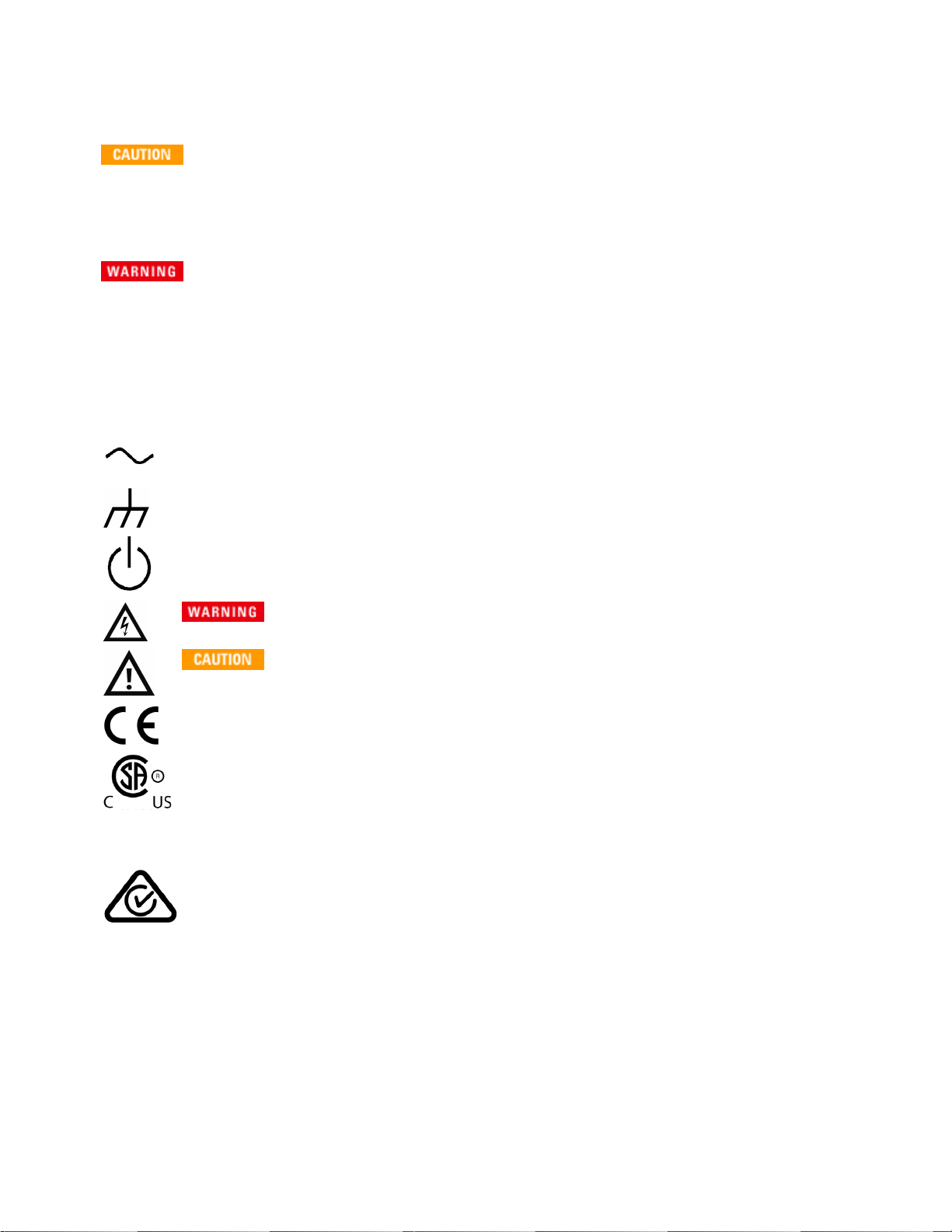
Safety Notices
A CAUTION notice denotes a hazard. It calls attention to an operating procedure, practice, or the like that,
if not correctly performed or adhered to, could result in damage to the product or loss of important data.
Do not proceed beyond a CAUTION notice until the indicated conditions are fully understood and met.
A WARNING notice denotes a hazard. It calls attention to an operating procedure, practice, or the like
that, if not correctly performed or adhered to, could result in personal injury or death. Do not proceed beyond a WARNING notice until the indicated conditions are fully understood and met.
Safety Symbols
Alternating current
Frame or chassis terminal
Standby supply. Unit is not completely disconnected from AC mains power when switch is off.
Risk of electric shock
Refer to accompanying documents
The CE mark is a registered trademark of the European Community.
The CSA mark with the 'c' and 'us' subscript indicates the instrument is certified to the applicable Canadian and United States of America standards respectively.
CAT II
(300V)
ISM 1-A This text indicates that the instrument is an Industrial Scientific and Medical Group 1 Class A product
ICES/NMB001
IEC Measurement Category II. Inputs may be connected to AC mains power (up to 300 VAC)
under Category II overvoltage conditions.
This product ismarked with the ACMA RCM mark for compliance in Australia / New Zealand. A
copy of the Manufacturer’s Australia Declaration of Conformity for this instrument can be
obtained by contacting your local Keysight Technologies Sales Representative.
(CISPR 11, Clause 4).
This ISM device complies with Canadian ICES-001.
Cet appareil ISM est conforme à la norme NMB-001 du Canada.
Keysight TruevoltSeries Operating and Service Guide
13
Page 13
Safety and Regulatory Information
This product complies with the WEEE Directive (2002/96/EC) marking equipment. The affixed
product label indicates that you must not discard thiselectrical/electronic product in
domestic household waste.
To return unwanted products, contact your local Keysight office, or see www.key-
sight.com/environment/product/ for more information.
This equipment isClass A suitable for professional use and is for use in electromagnetic environments outside of the home.
Contains one or more of the 6 hazardous substances above the maximum concentration value (MCV), 40
Year EPUP.
Safety Information
General
Do not use this product in any manner not specified by the manufacturer. The protective features of this
product may be impaired if it is used in a manner not specified in the operation instructions. Do not install
substitute parts or perform any unauthorized modification to the product. Return the product to a Keysight Technologies Sales and Service Office for service and repair to ensure that safety features are maintained.
Product Grounding
The instrument is a Class 1 product and is provided with a grounding-type power cord set. The instrument chassis and cover are connected to the instrument electrical ground to minimize shock hazard.
The ground pin of the cord set plug must be firmly connected to the electrical ground (safety ground)
terminal at the power outlet. Any interruption of the protective earth (grounding) conductor or disconnection of the protective earth terminal will cause a potential shock hazard that could result in personal injury or death.
Cleaning
To prevent electrical shock, disconnect the instrument from AC mains power and disconnect all test
leads before cleaning. Clean the outside of the instrument using a soft, lint-free, cloth slightly
dampened with water.Do not use detergent or solvents.Do not attempt to clean internally.If needed,
contact a KeysightTechnologies Sales and Service office to arrange for proper cleaning to ensure
that safety features and performance are maintained.
AC Power Cord
Removal of the AC power cord is the disconnect method to remove power from the instrument. Be
sure to allow for adequate access to the power cord to permit disconnection from AC power. Use
only the Keysightspecified power cord for the country of use or one with equivalent ratings.
14
Keysight TruevoltSeries Operating and Service Guide
Page 14

Safety and Regulatory Information
Do Not Remove Instrument Cover
Only qualified, service-trained personnel should remove the cover from the instrument. Service:
Unplug instrument from wall outlet, remove power cord, and remove all probes from all terminals
before servicing.
AC Mains Power Line Fuse
For continued protection against fire, replace the line fuse only with fuses of the specified type and rating. The instrument must be disconnected from AC mains power, and all measurement terminals
must be disconnected before changing the fuse.
Current Measurement Protection Fuse
For continued protection against fire, replace current-protection fuses only with fuses of the specified
type and rating. The instrument must be disconnected from AC mains power, and all measurement terminals must be disconnected before changing the fuse.
Front/Rear Switch
Do not change the position of the Front/Rear switch on the front panel while signals are present on
either the front or rear set of terminals. The switch is not intended as an active multiplexer. Switching
while current or high voltage is present may cause instrument damage and lead to the risk of electric
shock.
Do Not Operate in an Explosive Atmosphere
This instrument is not designed to be operated in an explosive environment. The instrument enclosure
complies with the IP 20 rating.
In Case of Damage
An instrument that appears damaged or defective should be made inoperative and secured against
unintended operation until qualified service personnel can repair it.
Self-Test
Before measuring any hazardous voltage or current, remove all test leads to the instrument, run the
TEST:ALL? query from the remote interface, and read the result to verify that the instrument is performing properly.
The TEST:ALL? query is a self-testthat returns +0 if the instrument passes and +1if the instrument
fails. You can also perform this query from the front panel by pressing [Shift] > [Utility] > Test/Admin >
Self Test > Full Test. If this self-test fails, make sure thatthe instrument is repaired and passes the
complete self-test before continuing.
Measuring AC Power Mains
The HI, LO, and current input terminals may be connected to AC mains power in IEC Category II installations for line voltages up to 300VAC. To avoid the danger of electric shock, do not connect the inputs
to AC mains power for line voltages above 300 VAC. See IEC Measurement Category II for further
information.
Keysight TruevoltSeries Operating and Service Guide
15
Page 15

Safety and Regulatory Information
Measuring Current with A Current Transformer
If a current transformer is used for measuring current, you must use a current transformer with
internal secondary protection. Using a current transformer without protection may result in a hazardous voltage resulting in a severe shock or death. In addition, this may cause damage to the instrument.
Crest Factor
Exceeding the crest factor limit may result in an inaccurate or lower reading display. Do not exceed
the crest factor limit to avoid instrument damage and risk of electric shock. The crest factor limit is listed in the product data sheet at www.keysight.com/find/truevolt-doc.
Measurement Limits
To avoid instrument damage and the risk of electric shock, do not exceed any of the Measurement Limits defined in the following section.
This product complies with EN/IEC 61326-2-1, for sensitive test and measurement equipment:
When subjected to transient radiated and/or conducted electromagnetic phenomena, the
product may have temporary loss of function or performance which is self-recovering. Recovery may take longer than 10 seconds.
When subjected to continuously present electromagnetic phenomena, some degradation of
performance may occur.
Unless otherwise noted in the specifications, this instrument or system is intended for indoor
use in an installation category II, pollution degree 2 environment per IEC 61010-1 and 664
respectively. It is designed to operate at a maximum relative humidity of 5% to 80% at 40 °C or
less (non-condensing). This instrument or system is designed to operate at altitudes up to
3000 meters, and at temperatures between 0 and 55 °C.
Measurement Limits
The Truevolt Series DMMs provide protection circuitry to prevent damage to the instrument and to protect
against the danger of electric shock, provided the Measurement Limits are not exceeded. To ensure safe
operation of the instrument, do not exceed the Measurement Limits shown on the front and rear panel,
and defined as follows:
16
Keysight TruevoltSeries Operating and Service Guide
Page 16
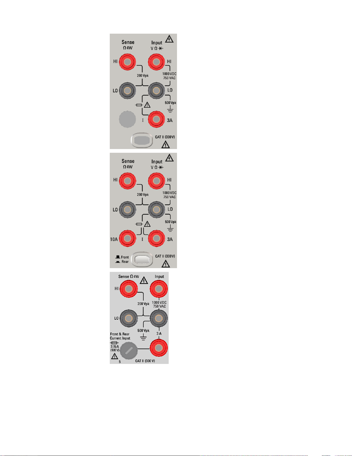
34460A Front Panel
Terminal Area
Safety and Regulatory Information
34461A, 34465A, 34470A
Front Panel
Terminal Area
34461A, 34465A, 34470A
Rear Panel
Terminal Area
Keysight TruevoltSeries Operating and Service Guide
17
Page 17

Safety and Regulatory Information
For the 34461A, 34465A, and 34470A, the Front/Rear switch selects the terminal set to be
used. DO NOT operate this switch while signals are present on the front or rear terminals.
The user-replaceable 3 A current-protection fuse is on the rear panel. There are 3 A and 10 A
(34461A, 34465A and 34470A) current-protection fuses located inside the unit. Contact your
Keysight Sales and Service Center or refer to product service documentation for replacement
instructions.
To maintain protection, replace fuses only with fuses of the specified type and rating.
Input Terminal Measurement Limits
Measurement Limits are defined for the input terminals:
Main Input (HI and LO) Terminals. The HI and LO input terminals are used for voltage, resistance, fre-
quency (period), capacitance, and diode test measurements. Two Measurement Limits are defined for
these terminals:
l
HI to LO Measurement Limit. The Measurement Limit from HI to LO (Input terminals) is 1000 VDC or
750 VAC, which is also the maximum voltage measurement. This limit can also be expressed as 1000
Vpk maximum.
l
LO to Ground Measurement Limit. The LO input terminal can safely "float" a maximum of 500 Vpk
relative to ground, where ground is defined as the Protective Earth Conductor in the AC mains power
cord connected to the instrument.
As implied by the above limits, the Measurement Limit for the HI input terminal is a maximum of 1500 Vpk
relative to ground when LO is at its maximum of 500 Vpk relative to ground.
Current Input Terminal. The current input ("I") terminal has a Measurement Limit of 3 A or 10 A (DC or
AC) between the "I" terminal (3 A or 10 A) and the LO input terminal. Note that the current input terminals
will always be at approximately the same voltage as the LO terminal, unless a current protection fuse is
open. The 10 A terminal isnot available on the 34460A.
Sense Terminal Measurement Limits
The HI and LO sense terminals are used for DCV ratio measurements and four-wire resistance and temperature measurements. The Measurement Limit is 200 Vpk for all of the terminal pairings: LO sense to LO
input, HI sense to LO input, and HI sense to LO sense.
The 200 Vpk limit on the sense terminals is the Measurement Limit. Operational voltages in resistance measurements are much lower – up to ± 12 V in normal operation.
18
Keysight TruevoltSeries Operating and Service Guide
Page 18

Safety and Regulatory Information
IEC Measurement Category II
To protect against the danger of electric shock, the Keysight Truevolt Series DMM protects the user from
AC mains power overvoltage events. When measuring AC mains, the HI and LO input terminals may be
connected to AC mains power up to 300 VAC under Measurement Category II conditions as defined
below.
IEC Measurement Category II includes electrical devices connected to AC mains power at an outlet on a
branch circuit. Such devices include most small appliances, test equipment, and other devices that plug
into a branch outlet or socket. The instrument may be used to make measurements with the HI and LO
inputs connected to AC mains power in such devices, or to the branch outlet itself (up to 300 VAC).
However, the instrument may not be used with its HI and LO inputs connected to AC mains power in permanently installed electrical devices such asthe main circuit-breaker panel, sub-panel disconnect boxes,
or permanently wired motors. Such devicesand circuits are subject to overvoltages that may exceed the
instrument’s protection capabilities.
Voltages above 300 VAC may be measured only in circuits that are isolated from AC mains power. However,
transient overvoltages are also present on circuits that are isolated from ACmains power. The instrument is
designed to safely withstand occasional transient overvoltages up to 1500 Vpk when measuring voltages
greater than 300 VAC. Do not use this equipment to measure circuits where transient overvoltages could
exceed this level.
Keysight 34138A Test Lead Set
The Keysight 34138A Test Lead Set, described below, is compatible with the Truevolt Series DMMs.
Test Lead Ratings
l Test Leads - 1000V, 15A
l Fine Tip Probe Attachments - 300V
l 3A Mini Grabber Attachment - 300V, 3A
l SMT Grabber Attachments - 300V, 3A
Operation
The Fine Tip, Mini Grabber, and SMT Grabber attachments plug onto the probe end of the Test Leads.
Maintenance
If any portion of the Test Lead Set is worn or damaged, do not use. Replace with a new Keysight 34138A
Test Lead Set.
If the Test Lead Set is used in a manner not specified by KeysightTechnologies, the protection
provided by the Test Lead Set may be impaired. Also, do not use a damaged or worn Test Lead Set. Personal injury or death may result.
Keysight TruevoltSeries Operating and Service Guide
19
Page 19

Safety and Regulatory Information
Declaration of Conformity
Declarations of Conformity for this product and for other Keysight products may be downloaded from the
Keysight Regulatory Web site:
http://regulations.products.keysight.com/DoC/search.htm
20
Keysight TruevoltSeries Operating and Service Guide
Page 20

Welcome
Welcome
This Operating and Service Guide contains information for using, programming, and servicing the Keysight
Truevolt Series Digital Multimeters (DMMs). If you have feedback on this document, please go to www.key-
sight.com/find/truevolt-docfeedback.
Introductory Information
Safety and Regulatory Information
Models and Options
Quick Start
Contacting Keysight Technologies
Introduction to the Instrument
User Information
Front Panel Menu Reference
Features and Functions
Remote Interface Configuration
LAN Configuration Procedure
Web Interface
Measurements
Triggering and Readings
Probe Hold
Math
Display
Utility Menu
Measurement Tutorial
Keysight TruevoltSeries Operating and Service Guide
21
Page 21

Welcome
SCPI Programming Reference
Welcome to SCPI
Introduction to the SCPI Language
Commands by Subsystem
Command Quick Reference
Range, Resolution, and NPLC
Resolution Table
VM Comp Output
SCPI Error Messages
Power-On and Reset State
Service and Repair
Service and Repair
Disassembly
Troubleshooting
Power Supplies
Self-Test Procedures
Battery Replacement
Installing the Optional GPIB Interface
User Replaceable Parts
Performance Verification
Performance Verification
Calibration Procedures
Calibration Procedures
34460A and 34461A Calibration Procedures
34465A and 34470A Calibration Procedures
Firmware Update
22
Keysight TruevoltSeries Operating and Service Guide
Page 22

Introduction to the Instrument
Introduction to the Instrument
The Keysight Technologies 34460A/61A/65A instruments are 6½-digit digital multimeters (DMMs); the
34470A is a 7½-digit DMM.
Instrument at a Glance
Front Panel at a Glance
Rear Panel at a Glance
Models and Options
Contacting Keysight Technologies
Instrument at a Glance
The instrument’s combination of bench-top and system features make it a versatile solution now and in
the future. The instrument can make a wide range of accurate and flexible measurements.
Display – Easily display, save and document your measurement results
l High usability with an intuitive, menu driven user interface
l Histogram, trend chart (not available on the 34460A), meter, and numeric views on a high-resolution
color display
l USB, LAN (optional on 34460A), and optional GPIB interface
l Drag and drop, driverless USB connectivity
Measurements – Keysight’s Truevolt measurement performance with modern I/O accessibility
l Patented, metrology-level performance that serves as the foundation for all measurements
Programming Language
l SCPI (Standard Commands for Programmable Instruments) programming language
Keysight TruevoltSeries Operating and Service Guide
23
Page 23
Introduction to the Instrument
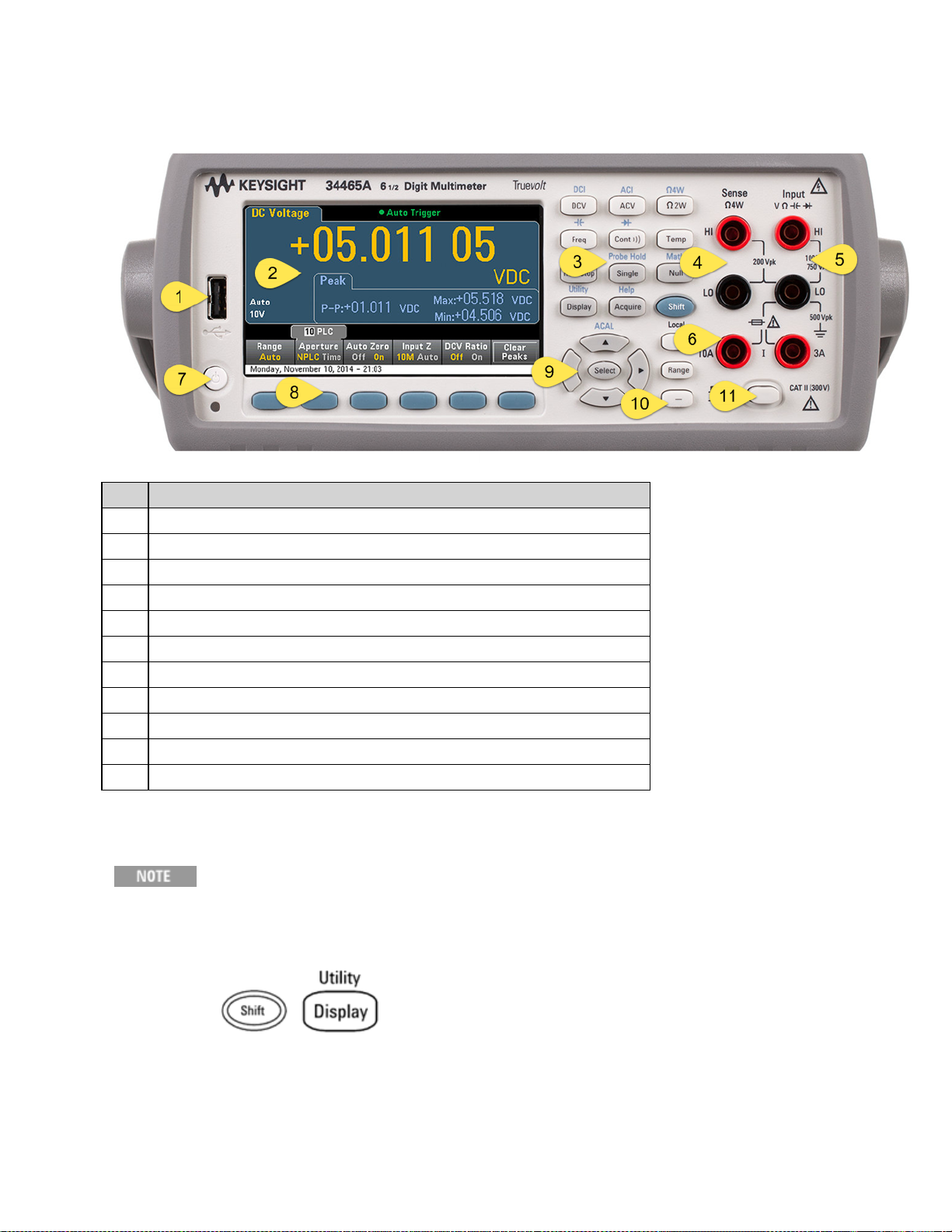
Front Panel at a Glance
Item Description
1 USB Port
2 Display
3 Measurement Configuration and Instrument Operation Keys
4 HI and LO Sense Terminals
5 HI and LO Input Terminals
6 AC/DC Current Input Terminals (10 A terminal not available on 34460A)
7 On/Standby Switch
8 Softkeys
9 Cursor Navigation Keypad
10 Range Selection Keys
11 Front/Rear Switch (34461A/65A/70A only)
Front Panel Keys
Some of the front panel keys have text above them. This indicates that the key has a
function that you can access by pressing and releasing [Shift] before pressing the key.
For example, if you press and release [Shift] before pressing [Display], you will access
the [Utility] function:
24
Keysight TruevoltSeries Operating and Service Guide
Page 24
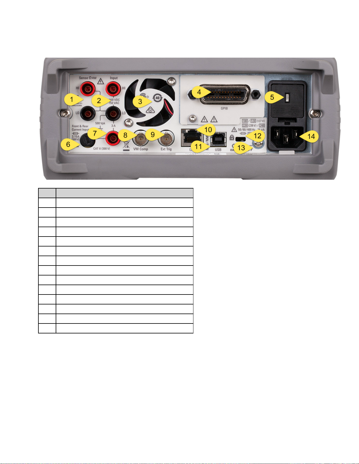
Rear Panel at a Glance
Introduction to the Instrument
Item Description
1 HI and LO Sense Terminals (34461A/65A/70A only)
2 HI and LO Input Terminals (34461A/65A/70A only)
3 Fan Vents (34461A/65A/70A only)
4 GPIB Connector (optional)
5 AC Mains Line Voltage Selector and Fuse Access
6 3 A Current Terminal Fuse
7 3 A Current Terminal (34461A/65A/70A only)
8 Voltmeter Measurement Complete Output
9 External Trigger Input
10 Local Area Network (LAN) Connector
11 USB Interface Connector
12 Instrument Cable Lock
13 Chassis Ground Screw
14 AC Mains Input
Keysight TruevoltSeries Operating and Service Guide
25
Page 25

Introduction to the Instrument
Models and Options
The available Truevolt Digital Multimeter (DMM) models are:
l 34460A - 6½-digit Basic DMM
l 34461A - 6½-digit 34401A Replacement DMM
l 34465A - 6½-digit DMM
l 34470A - 7½-digit DMM
The factory-installed options and the options that can be installed by you or a distributor are listed in the
tables below. You can determine the installed options from the instrument's front panel by pressing
[Shift] > [Help] > About.
Options Installed at Factory
34460A 34461A 34465A 34470A Description
34460ALAN
34460ASEC
34460AGPB
34460AACC
34460AZ54
*N/A *N/A 34465A-
*N/A *N/A 34465A-
*N/A Standard
34461ASEC
34461AGPB
*N/A Standard
34461AZ54
*N/A Standard
34465ASEC
34465AGPB
*N/A Standard
34465AZ54
DIG
MEM
*N/A Standard
34470ASEC
34470AGPB
*N/A Standard
34470AZ54
34470ADIG
34470AMEM
Rear panel LAN/LXI web interface, external triggering for
34460A.
NISPOM and file security for Truevolt series DMMs license.
User-installable GPIB interface module
Accessory kit for 34460A - Test Leads, USB Cable
Certificate of calibration – ANSI/NCSL Z540.3-2006, printed
Digitizing and advanced triggering. Now included with
latest firmware update.
2 MB memory license
Options Installed by Distributor or End Customer
Product
Number
3446LANU Option *N/A -
3446SECU Option Option Option Option NISPOM and file security for Truevolt series
3446GPBU Option Option Option Option User-installable GPIB interface module
3446ACCU Option *N/A -
3446MEMU *N/A *N/A Option Option 2 MB memory for 34465A and 34470A Truevolt
*N/A = Not Applicable.
26
34460A 34461A 34465A 34470A Description
Standard
Standard
*N/A Standard
*N/A Standard
*N/A Standard
*N/A Standard
Enable rear panel LAN/LXI web interface,
external triggering for 34460A
DMMs license.
Accessory kit for 34460A - Test Leads, USB
Cable
DMMs license
Keysight TruevoltSeries Operating and Service Guide
Page 26

Introduction to the Instrument
Remote Interface Configuration
If you have the security option installed on your instrument, the instrument must be unsecured with the
security code to perform many of these actions.
The instrument supports remote interface communication over three interfaces: GPIB (optional), USB, and
LAN (optional on 34460A). All three are "live" at power up when the instrument ships from the factory.
l
GPIB Interface: Set the instrument's GPIB address and connect to your PC using a GPIB cable.
l
USB Interface: Use the rear-panel USB connector to communicate with your PC. For details, see USB
Settings.
l
LAN Interface: By default, DHCP is on, which may enable communication over LAN. The acronym
DHCP stands for Dynamic Host Configuration Protocol, a protocol for assigning dynamic IP addresses
to networked devices. With dynamic addressing, a device can have a different IP address every time it
connects to the network.
Connectivity Software
l
The instrument ships with the Keysight Automation-Ready CD. This CDcontains Keysight IO Librar-
ies Suite software, which must be installed to enable remote-interface operations. The CDauto-starts
and provides information on installing the software. Also includes Keysight Technologies
USB/LAN/GPIB Connectivity Guide, which contains additional information.
GPIB Configuration
Each device on the GPIB (IEEE-488) interface must have a unique whole number address between 0 and
30. The instrument ships with a default address of 10, and the GPIB address is displayed at power-on.
l This setting is non-volatile; it will not be changed by power cycling or *RST or SYSTem:PRESet.
l Your computer’s GPIB interface card addressmust not conflict with any instrument on the interface
bus.
l
Front Panel: Press [Utility] > I/O Config > GPIB Settings. From this menu, you can set the GPIB
address and turn GPIB on or off. After making changes, you must cycle power on the instrument for
the change to take effect.
l
SCPI:
SYSTem:COMMunicate:GPIB:ADDRess <address>
SYSTem:COMMunicate:ENABle {ON|1|OFF|0},GPIB
Keysight TruevoltSeries Operating and Service Guide
27
Page 27

Introduction to the Instrument
LAN Configuration
The following sections describe the primary front panel LAN configuration functions, including SCPI commands where applicable. Some LAN configuration functions can be performed only via SCPI. See SYSTem
Subsystem - I/O Configuration for all LAN configuration commands, and see LAN Configuration Procedure to configure the LAN via the front panel.
Some LAN settings require you to cycle instrument power to activate them. The instrument briefly displays a message when this is the case, so watch the screen closely as
you change LAN settings.
Resetting the LAN
You can clear the Web Interface password, turn DHCP on, and restart the LAN at any time:
l
Front Panel:[Utility] > I/O Config > LAN Reset
The message "Performing LAN Reset" is displayed while the LAN is reset.
l
SCPI: LXI:RESet
DHCP On/Off
DHCP (Dynamic Host Configuration Protocol) can automatically assign a dynamic IP addressto a LAN
device. This is typically the easiest way to configure the instrument for LAN.
l This setting is non-volatile; it will not be changed by power cycling or *RST or SYSTem:PRESet.
l
Front Panel:[Utility] > I/O Config > LAN Settings > Modify Settings
Then set the first softkey to DHCP to use DHCP to automatically assign an IP address.
l
SCPI: SYSTem:COMMunicate:LAN:DHCP {ON|1|OFF|0}
l
If you change this parameter, you must either press the Apply Changes softkey (front panel) or send
SYSTem:COMMunicate:LAN:UPDate (remote interface) for the change to take effect.
To manually set an IP address, Subnet Mask, or Default Gateway, turn DHCP off, then change the IP setup
as described below.
28
Keysight TruevoltSeries Operating and Service Guide
Page 28

Introduction to the Instrument
IP Address
You can enter a static IP address for the instrument as a four-byte integer expressed in dot notation. Each
byte isa decimal value, with no leading zeros (for example, 169.254.2.20).
l If DHCP is on, it attempts to assign an IP address to the instrument. If it fails, Auto-IP attempts to
assign an IP address to the instrument.
l Contact your LAN administrator to obtain an IP address.
l This setting is non-volatile; it will not be changed by power cycling or *RST or SYSTem:PRESet.
l
Front Panel:[Utility] > I/O Config > LAN Settings > Modify Settings
Then set the first softkey to Manual and press IP Address to enter a new IP address.
l
SCPI: SYSTem:COMMunicate:LAN:IPADdress"<address>"
l
If you change this parameter, you must either press the Apply Changes softkey (front panel) or send
SYSTem:COMMunicate:LAN:UPDate (remote interface) for the change to take effect.
Subnet Mask
Subnetting allows the LAN administrator to subdivide a network to simplify administration and minimize
network traffic. The subnet mask indicates the portion of the host address used to indicate the subnet.
l Contact your LAN administrator for details.
l This setting is non-volatile; it will not be changed by power cycling or *RST or SYSTem:PRESet.
l
Front Panel:[Utility] > I/O Config > LAN Settings > Modify Settings
Then set the first softkey to Manual and press Subnet Mask to enter a new subnet mask with the
arrow keys (for example: 255.255.0.0).
l
SCPI: SYSTem:COMMunicate:LAN:SMASk "<mask>"
l
If you change this parameter, you must either press the Apply Changes softkey (front panel) or send
SYSTem:COMMunicate:LAN:UPDate (remote interface) for the change to take effect.
Keysight TruevoltSeries Operating and Service Guide
29
Page 29

Introduction to the Instrument
Default Gateway
A gateway is a network device that connects networks. The default gateway setting is the IP address of
such a device.
l You need not set a gateway address if using DHCP.
l Contact your LAN administrator for details.
l This setting is non-volatile; it will not be changed by power cycling or *RST or SYSTem:PRESet.
l
Front Panel:[Utility] > I/O Config > LAN Settings > Modify Settings
Then set the first softkey to Manual and press More and Gateway. Then set the appropriate gateway
address using the arrow keys.
l
SCPI: SYSTem:COMMunicate:LAN:GATeway "<address>"
l
If you change this parameter, you must either press the Apply Changes softkey (front panel) or send
SYSTem:COMMunicate:LAN:UPDate (remote interface) for the change to take effect.
Hostname
A hostname is the host portion of the domain name, which is translated into an IP address.
l The instrument receives a unique hostname at the factory, but you may change it. The hostname must
be unique on the LAN.
l The name must start with letter; other characters can be an upper or lower case letters, numeric digits,
or dashes("-").
l This setting is non-volatile; it will not be changed by power cycling or *RST or SYSTem:PRESet.
l
Front Panel:[Utility] > I/O Config > LAN Settings > Modify Settings
Then press Host Name and enter the hostname with the front panel arrow keys.
l
SCPI: SYSTem:COMMunicate:LAN:HOSTname "<name>"
l
If you change this parameter, you must either press the Apply Changes softkey (front panel) or send
SYSTem:COMMunicate:LAN:UPDate (remote interface) for the change to take effect.
Domain Name
A domain name is a registered Internet name that gets translated into an IP address. You cannot set it from
the front panel or SCPI.
30
Keysight TruevoltSeries Operating and Service Guide
Page 30

Introduction to the Instrument
DNS Server
DNS (Domain Name Service) is an Internet service that translates domain names into IP addresses. The
DNS server address is the IP address of a server that performs this service.
l Normally, DHCP discovers DNS address information; you only need to change this if DHCP is unused
or not functional. Contact your LAN administrator for details.
l This setting is non-volatile; it will not be changed by power cycling or *RST or SYSTem:PRESet.
l
Front Panel:[Utility] > I/O Config > LAN Settings > Modify Settings
Then set the first softkey to Manual and press More and Primary DNS or Second DNS to enter a DNS
address using the front panel arrow keys.
l
SCPI: SYSTem:COMMunicate:LAN:DNS[{1|2}] "<address>"
l
If you change this parameter, you must either press the Apply Changes softkey (front panel) or send
SYSTem:COMMunicate:LAN:UPDate (remote interface) for the change to take effect.
Current Configuration (LAN)
l
Press[Utility] > I/O Config > LAN Settings to view the MAC address and current LAN configuration.
There is no equivalent SCPI command.
l If the instrument goes into remote, all LAN changes will be canceled and the display will go to a dif-
ferent screen. Re-selecting the LAN Settings page will display the new settings if a LAN restart took
place.
Web Interface
The instrument includes a built-in Web Interface for remote instrument access and control over LAN via a
Web browser. For details, see Web Interface.
Keysight TruevoltSeries Operating and Service Guide
31
Page 31

Introduction to the Instrument
LAN Configuration Procedure
There are several parameters that you might need to set to establish network communication using the
LAN interface. Primarily, you will need to establish an IP address. You might need to contact your network
administrator for help in establishing communication with the LAN interface.
If your instrument has the secure (SEC) option, the instrument must be unsecured to change most LAN settings.
1. Press [Utility] > I/O Config > LAN Settings.
2. You can select Modify Settings to change the LAN settings, or you can turn LAN Services on and off
or restore the LAN settings to default values.
3. To change settings, press Modify Settings. To access most items on this screen, use the first softkey
to switch from DHCP to Manual. With DHCP on, an IP address will automatically be set by DHCP
(Dynamic Host Configuration Protocol) when you connect the instrument to the network, provided
the DHCP server isfound and is able to do so. DHCP also automatically deals with the subnet mask,
gateway address, DNS, WINS, and domain name, if required. This is typically the easiest way to establish LAN communication for your instrument; all you need to do is leave DHCP on. Contact your LAN
administrator for details.
4. Establish an "IP Setup."
If you are not using DHCP (the first softkey is set to Manual), you must establish an IP setup, including
an IP address, and possibly a subnet mask and gateway address. The IP Address and Subnet Mask
buttons are on the main screen, and you press More to configure the Gateway.
Contact your network administrator for the IP address, subnet mask, and gateway to use. All IP
addresses take the dot-notation form "nnn.nnn.nnn.nnn" where "nnn" in each case is a byte value in
the range 0 through 255. You can enter a newIP address using the front panel arrow keys. Do not
enter leading zeros.
32
Keysight TruevoltSeries Operating and Service Guide
Page 32

Introduction to the Instrument
5. Configure the "DNS Setup" (optional)
DNS (Domain Name Service) is an Internet service that translates domain names into IP addresses. Ask
your network administrator whether DNS is in use, and if it is, for the host name, domain name, and
DNS server address to use.
a. Set the "hostname." Press Host Name and enter the hostname. A hostname isthe host portion of
the domain name, which is translated into an IP address. The hostname is entered as a string using
the front panel arrow keys to select and change characters. The hostname may include letters,
numbers, and dashes ("-").
b. Set the "DNS Server" addresses. From the LAN configuration screen, press More to go to the
second of three sets of softkeys.
Enter the Primary DNS and Second DNS. See your network administrator for details.
More about IP Addresses and Dot Notation
Dot-notation addresses ("nnn.nnn.nnn.nnn" where "nnn" is a byte value from 0 to 255) must be expressed
with care, as most PC web software interprets byte values with leading zeros as octal (base 8) numbers. For
example, "192.168.020.011" is actually equivalent to decimal "192.168.16.9" because ".020" is interpreted as "16" expressed in octal, and ".011" as "9". To avoid confusion, use only decimal values from 0 to
255, with no leading zeros.
Keysight TruevoltSeries Operating and Service Guide
33
Page 33

Introduction to the Instrument
Firmware Update
Use the following procedure to update instrument firmware:
Do not turn off the instrument during the update.
1. Press [Help] > About to determine what instrument firmware version iscurrently installed.
2.
Go to www.keysight.com/find/truevolt and use the links there to find the latest firmware version. If
this matches the version installed on your instrument, there is no need to continue with this procedure. Otherwise, download the firmware update utility and a ZIP file of the firmware. Detailed firmware instructions are in the Firmware Update Utility Instructions located on the download page.
3.
Unzip the ZIP file and use the firmware update utility to prepare a USB drive with the updated firmware:
4. Attach the USB drive to the instrument front panel and press [Utility] > Test / Admin > Firmware
Update to update the firmware. If the security option is installed, unlock the instrument with the secur-
ity code before installing firmware.
Important: In order to update the instrument firmware from remote, the model number in the *IDN?
response must match the actual instrument model number. If you have changed the instrument's *IDN?
response to another instrument, when attempting to update the firmware from remote, you will see this
error: The instrument is not supported by this firmware file. To update the firmware, either update using
the front panel procedure or, from remote, use SYSTem:IDENtify to set the *IDN? to match the actual
model number, update the firmware, and then use SYSTem:IDENtify again to set the *IDN? response to the
other model number.
34
Keysight TruevoltSeries Operating and Service Guide
Page 34

Introduction to the Instrument
Contacting Keysight Technologies
You can contact Keysight Technologies for warranty, service, or technical support.
In the United States: (800) 829-4444
In Europe: 31 20 547 2111
In Japan: 0120-421-345
Use www.keysight.com/find/assist to contact Keysight worldwide, or contact your Keysight Technologies rep-
resentative.
Keysight TruevoltSeries Operating and Service Guide
35
Page 35

Quick Start
Quick Start
This section describes basic procedures to help you get started quickly with the instrument.
l Prepare Instrument for Use
l Adjust the Carrying Handle
l Use Built-in Help System
l Rack Mount the Instrument
Prepare Instrument for Use
Verify that you received the following items. If anything is missing, please contact your nearest Keysight
sales office or Keysight authorized reseller.
l Power cord (for country of destination)
l Certificate of Calibration (optional)
l
Keysight Automation-Ready CD (Keysight IO Libraries Suite) (optional on 34460A)
l Supplemental documentation packet
l USB 2.0 cable (optional on 34460A)
The latest product documentation is available at www.keysight.com/find/truevolt-doc. For doc-
umentation for mobile devices, see www.keysight.com/find/truevolt-mobilehelp.
To download the Digital Multimeter Connectivity Utility, go to www.key-
sight.com/find/DMMutilitysoftware.
36
Keysight TruevoltSeries Operating and Service Guide
Page 36

Setting the AC Mains Line Voltage Selector and Fuse Installation
Before plugging the instrument into AC mains power, verify that the line voltage
setting visible on the back of the AC mains input module is correct for the AC
mains power source being connected. The line voltage selections are shown in a
box on the rear panel immediately to the left of the AC mains input module.
Other nominal line voltages are shown in parentheses.
Verify that the correct fuse is installed. To replace a blown fuse or verify the correct
fuse,
pull it gently from the fuse drawer and insert thecorrect working fuse. Use only a
5x20 mm,
time-lag, 0.25 A, 250 V certified fuse. The Keysight part number is 2110-0817.
Quick Start
AC MAINS Nominal Line Voltage
Range
100 - 115 100
120 - 127 120
202 - 230 220
240 240
AC Mains Line Voltage
Selector
Keysight TruevoltSeries Operating and Service Guide
37
Page 37

Quick Start
Use the following procedure to configure the line voltage selector:
Step1 Lift tab (1) and pull the fuse drawer (2) from the rear panel.
Step2 Remove the line-voltage selector and rotate it so the correct voltage will
appear in the fuse holder window.
Step3
Step4 Replace the fuse holder assembly by sliding it into the rear panel.
Verify that the correct fuse is installed. To replace a blown fuse or
verify the correct fuse,
pull it gently from the fuse drawer and insert the correct working
fuse. Use only a 5x20 mm,
time-lag, 0.25 A, 250 V certified fuse. The Keysight part number is
2110-0817.
38
Keysight TruevoltSeries Operating and Service Guide
Page 38

Quick Start
Product Grounding
The instrument is a Class 1 product and is provided with a grounding-type power cord set. The instrument chassis and cover are connected to the instrument electrical ground to minimize shock hazard.
The ground pin of the cord set plug must be firmly connected to the electrical ground (safety ground)
terminal at the power outlet. Any interruption of the protective earth (grounding) conductor or disconnection of the protective earth terminal will cause a potential shock hazard that could result in personal injury or death.
Connect Power and I/O Cables
Connect the power cord and LAN, GPIB, or USB cable as desired. After you turn on the instrument (as
described below), the instrument will run a power-on self test and then display a message about how to
obtain help, along with the current IP address. It also displays the GPIB address (if applicable).
The instrument's default measurement function isDC Voltage (DCV), with autoranging enabled.
Power Switch
Pressthe power switch in the lower left corner of the front panel. If the instrument does not turn on, verify
that the power cord is firmly connected and that the fuse is good and the line voltage selector is set correctly, as described above. Also make sure that the instrument is connected to an energized power source.
If the LED below the power switch is off, there is no AC mains power connected. If the LED is amber, the
instrument isin standby mode with AC mains power connected, and if it is green, the instrument is on.
In certain circumstances, the amber LED can come on even if the wrong line voltage is selected. In this
case, the instrument may not power on.
If the power-on self test fails, the display shows Error in the upper right corner. It also displays a message
describing the error. See SCPI Error Messagesfor information on error codes. See Service and Repair -
Introduction for instructions on returning the instrument for service.
To turn off the instrument, press and hold the power switch for about 500 ms. This prevents you from accidentally turning off the instrument by brushing against the power switch.
If you turn off the instrument by disconnecting power (this is not recommended), the instrument turns on
as soon as you re-apply power. You will not need to press the power switch.
Keysight TruevoltSeries Operating and Service Guide
39
Page 39

Quick Start
Adjust the Carrying Handle
The handle hasthree positions, shown below.
To adjust the handle position, grasp the sides of the handle, pull outward, and rotate the handle.
40
Keysight TruevoltSeries Operating and Service Guide
Page 40

Quick Start
Use Built-in Help System
The built-in help system provides context-sensitive help on any front panel key or menu softkey. A list of
help topics is also available to help you learn about the instrument.
View the help information for a front panel key
Pressand hold any softkey or button, such as [Display].
If the message contains more information than will fit on the display, pressthe down arrow softkey to
scroll down.
PressDone to exit Help.
Keysight TruevoltSeries Operating and Service Guide
41
Page 41
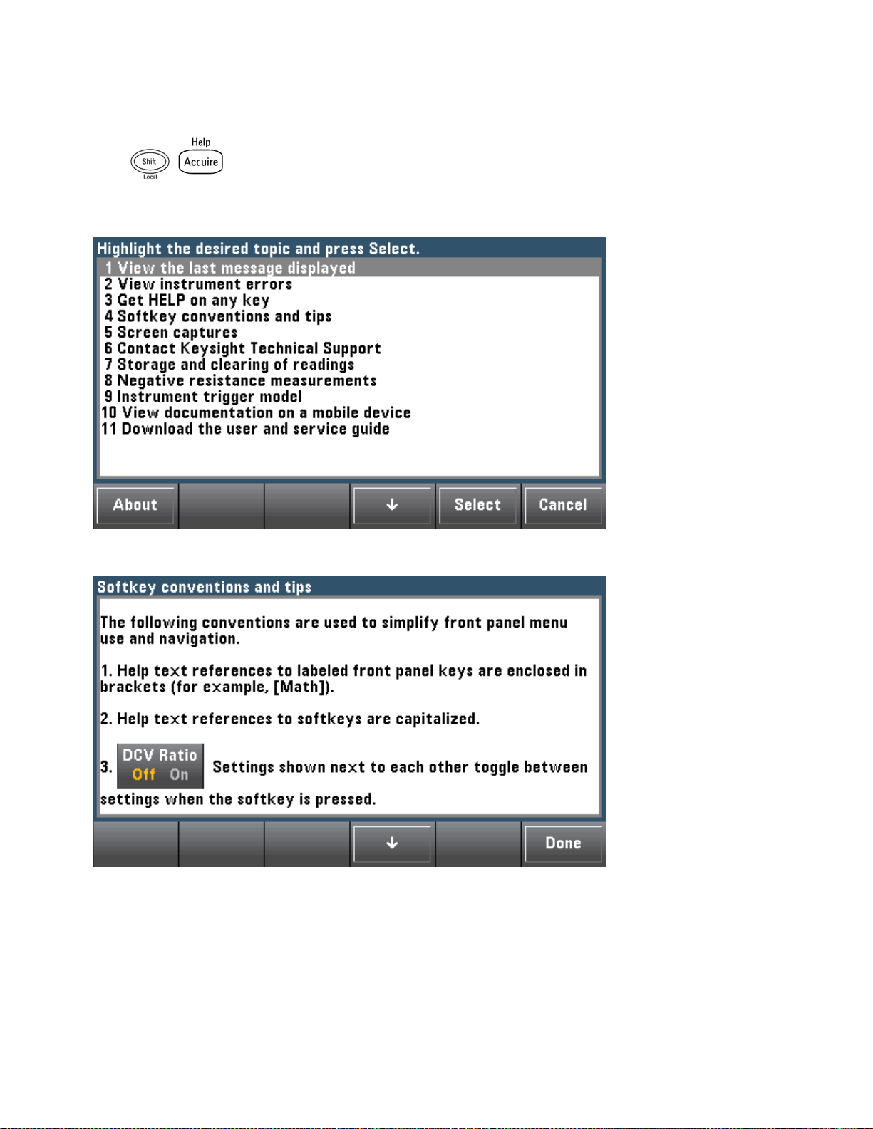
Quick Start
View the list of help topics and use interactive demos
Press to view the list of help topics. Press the arrow softkeys or use the front panel arrow
keys to highlight the desired topic. Then press Select. You can also press Demos to run interactive demos
on how to use the instrument.
In this case, the following help topic appears:
42
Keysight TruevoltSeries Operating and Service Guide
Page 42

Quick Start
View the list of recent instrument errors.
Press and choose View instrument errors from the list of help topics. This displays the
instrument's error queue, which includes up to 20 errors.
View the help information for displayed messages.
Whenever a limit is exceeded or any other invalid configuration isfound, the instrument displays a message. The built-in help system provides additional information on the most recent message. Press [Shift] >
[Help], select View the last message displayed, and press Select.
PressDone to exit Help.
Local Language Help
All messages, context-sensitive help, and help topics are available in English, Chinese,
French, German, Japanese, Korean, and Russian. To select the local language, press
[Utility] > System Setup > User Settings > Help Lang. Then select the desired lan-
guage.
The menu softkey labels and status line messages are not translated.
Keysight TruevoltSeries Operating and Service Guide
43
Page 43

Quick Start
Rack Mount the Instrument
You can mount the instrument in a standard 19-inch rack cabinet using one of two optional kits, each of
which includes instructions and mounting hardware. You may also mount Another Keysight System II
instrument of the same height and width beside the instrument.
To prevent overheating, do not block airflow to or from the instrument. Allow enough
clearance at the rear, sides, and bottom of the instrument to permit adequate internal
air flow.
Remove the carrying handle and the front and rear bumpers before rack-mounting the instrument.
Removing the Handle and Bumpers
To remove the handle, rotate it to vertical and pull the ends outward.
To remove the rubber bumper, stretch a corner and then slide it off.
Front Rear (bottom view)
Rack Mounting a Single Instrument
To rack mount a single instrument, order adapter kit 5063-9240.
Rack Mounting Instruments Side-by-Side
To rack mount two instruments side-by-side, order lock-link kit 5061- 8769 and flange kit 5063-9212. Be
sure to use the support rails in the rack cabinet.
44
Keysight TruevoltSeries Operating and Service Guide
Page 44

Quick Start
Sliding Support Shelf
To install one or two instruments in a sliding support shelf, order shelf 5063-9255 and slide kit 1494-
0015. For a single instrument, also order filler panel 5002-3999.
Keysight TruevoltSeries Operating and Service Guide
45
Page 45

Features and Functions
Features and Functions
This section contains details on instrument features, including front panel and remote interface operation.
Read the Front Panel Menu Reference first. See Introduction to SCPI Language for details on SCPI com-
mands and queries.
This section covers:
Front Panel Menu Reference
Measurements
Triggering and Readings
Probe Hold
Math Menu
Display Menu
Utility Menu
Web Interface
Throughout this document, "default" states and values are identified. These are the power-on default
states when the instrument is shipped from the factory.
46
Keysight TruevoltSeries Operating and Service Guide
Page 46

Features and Functions
Continuous, Data Log, and Digitize Modes
The 34465A/70A can operate in the continuous, data log, or digitize mode as described below.
The 34460A/61A DMMs always operate in the continuous mode -data log and digitize modes
are not available on these models.
Continuous Mode
Continuous mode is the default mode for all Truevolt DMMs. With the factory default settings, the DMM
continuously makes DCV measurements with autorange and autozero on, NPLC set to 10 PLCs, etc. (see
factory defaults for details).
Data Log Mode
The Data Log mode is standard on the 34465A and 34470A only, as is available only from the DMM's front
panel. Data Log mode provides a front–panel user interface that allows you to set up data logging into the
instrument’s non–volatile memory, or to internal/external file(s), without programming, and without a connection to a computer. Once you have finished collecting data, you can view it from the front panel, or you
can transfer the data to your computer. Data Log mode allows you to log a specified number of readings,
or readings acquired for a specified period of time, to instrument memory or to internal or external data
files.
To select Data Log mode, press [Acquire] Acquire > Data Log. You can then select the Sample Interval
(time between measurements - for example, 500 ms), Duration as either an amount of Time or a number of
Readings, whether to Start after a Delay or at a specific Time of Day, and whether to Log to Memory or Log
to File(s). After configuring the data logging parameters, press [Run/Stop]. Data logging will begin fol-
lowing the specified Delay or at the specified Time of Day.
Digitize Mode
The digitize mode applies only to the 34465A/70A with the DIG option, and asis available only from the
DMM's front panel. The digitized mode provides a front–panel user interface that allows you to quickly set
up digitized measurements.
Digitizing is the processof converting a continuous analog signal, such as a sine wave, into a series of discrete samples (readings). The figure below shows the result of digitizing a sine wave. This chapter discusses
the various ways to digitize signals. The importance of the sampling rate, and how to use level triggering.
Keysight TruevoltSeries Operating and Service Guide
47
Page 47

Features and Functions
Data Log and Digitize Mode Default Settings
On entering data log or digitize mode, the DMM configures these settings:
l Trigger count set to 1 (trigger count is normally infinite when in Local and is not settable from the
front panel).
l Secondary measurements are turned off.
l Math smoothing is turned off.
l Statistics are cleared.
l Histogram is cleared.
l Trend chart is changed from the continuous, bucketized mode, to simple data graph.
Additional Data Log Default Settings
On entering data log mode, the DMM configures these settings:
l Trigger source isset to auto.
l Trigger delay is set to auto.
l Pretrigger count is set to zero.
l Samples per trigger is set according to the data log duration (time or samples).
l Sample timer is put in timer (not immediate) mode and sample time is set according to the data log
sample interval.
48
Keysight TruevoltSeries Operating and Service Guide
Page 48

Features and Functions
Additional Digitize Default Settings
On entering digitize mode, the DMM configures these settings:
l If trigger source is set to manual it is changed to auto. (external and level remain asis.)
l Limits mode is turned off.
l Scaling is turned off.
l Statistic and histogram are put in post-processing mode (computed after digitize is complete).
l On the selected function (DCV or DCI) and for the new function if changed:
l Autorange is turned off.
l Autozero is turned off.
l NPLC and aperture are set to their minimum values.
l If trigger source is external or level, the pretrigger count is set to the digitize pretrigger count setting
(default of 0).
l Samples per trigger is set according to the digitize duration (time or samples).
l Sample timer is put in timer (not immediate) mode and Sample timer is set according to the digitize
sample rate or sample interval.
l Trend Chart mode is changed to bucketized when data logging to a file.
l On return to Continuous mode, settings are left as done in data log or digitize mode except:
l Sample source is set to immediate.
l Pretrigger count is set to 0.
l Samples per trigger is set to 1.
l Trigger count is set to infinite.
Keysight TruevoltSeries Operating and Service Guide
49
Page 49

Features and Functions
Front Panel Menu Reference
The following table summarizes the front panel keys and the menu structure.
Key Purpose
Configure DC voltage measurements, including DCV ratio measurements:
Range: Autorange (default), 100 mV, 1 V, 10 V, 100 V, or 750 V
Aperture NPLC: 0.02, 0.2, 1, 10, 100. Default: 10 (34460A/61A)
0.02, 0.06, 0.2, 1, 10, 100. Default: 10 (34465A/70A without DIG option)
0.001, 0.002, 0.006, 0.02, 0.06, .2, 1, 10, 100. Default: 10 (34465A/70A with
DIG option)
See Range, Resolution and NPLC for more information.
Aperture Time (applies only to the 34465A and 34470A): (Without the
DIGoption) 200µs to 1 s (2 µs resolution), default: 100 ms. (With the DIG option)
20 µs to 1 s (2 µs resolution), default: 100 ms.
Auto Zero: Off or On (default)
Input Z: 10 MΩ (default) or HighZ (> 10 GΩ)
DCV Ratio: Off (default) or On
Configure DC current measurements:
Terminals: 3 A or 10 A
Range: Auto, 100 µA, 1 mA, 10 mA, 100 mA, 1 A, 3 A, or 10 A (when terminals set
to 10 A). The 34465A and 34470A have additional 1 µA and 10 µA DC current
ranges.
Aperture NPLC: 0.02, 0.2, 1, 10, 100. Default: 10 (34460A/61A)
0.02, 0.06, 0.2, 1, 10, 100. Default: 10 (34465A/70A without DIG option)
0.001, 0.002, 0.006, 0.02, 0.06, .2, 1, 10, 100. Default: 10 (34465A/70A with
DIG option)
See Range, Resolution and NPLC for more information.
Aperture Time (applies only to the 34465A and 34470A): (Without the
DIGoption) 200µs to 1 s (2 µs resolution), default: 100 ms. (With the DIG option)
20 µs to 1 s (2 µs resolution), default: 100 ms.
Auto Zero: Off or On (default)
Configure AC voltage measurements:
Range: Autorange (default), 100 mV, 1 V, 10 V, 100 V, or 750 V
Filter: >3 Hz, >20 Hz, >200 Hz
Configure AC current measurements:
50
Terminals: 3 A or 10 A
Range: Auto, 100 µA, 1 mA, 10 mA, 100 mA, 1 A, 3 A, or 10 A (when terminals set
to 10 A)
Filter: >3 Hz, >20 Hz, >200 Hz
Keysight TruevoltSeries Operating and Service Guide
Page 50
Key Purpose
Configure 2-wire resistance measurements:
Range: 100 Ω, 1 kΩ, 10 kΩ, 100 kΩ, 1 MΩ, 10 MΩ, 100 MΩ, 1 GΩ (34465A and
34470A only) or Auto (default). Note: The approximate current sourced for each
range (for example, ~1mA) is shown on each range softkey.
Aperture NPLC: 0.02, 0.2, 1, 10, 100. Default: 10 (34460A/61A)
0.02, 0.06, 0.2, 1, 10, 100. Default: 10 (34465A/70A without DIG option)
0.001, 0.002, 0.006, 0.02, 0.06, .2, 1, 10, 100. Default: 10 (34465A/70A with
DIG option)
See Range, Resolution and NPLC for more information.
Aperture Time (applies only to the 34465A and 34470A): (Without the
DIGoption) 200µs to 1 s (2 µs resolution), default: 100 ms. (With the DIG option)
20 µs to 1 s (2 µs resolution), default: 100 ms.
Auto Zero: Off or On (default)
OffstComp: Off (default) or ON. Applies only to the 34465A and 34470A.
Low Power: Disables (Off) or enables (On) low power measurements. Applies only
to the 34465A and 34470A.
Configure 4-wire resistance measurements.
Features and Functions
Range: 100 Ω, 1 kΩ, 10 kΩ, 100 kΩ, 1 MΩ, 10 MΩ, 100 MΩ, 1 GΩ (34465A and
34470A only) or Auto (default). Note: The approximate current sourced for each
range (for example, ~1mA) is shown on each range softkey.
Aperture NPLC: 0.02, 0.2, 1, 10, 100. Default: 10 (34460A/61A)
0.02, 0.06, 0.2, 1, 10, 100. Default: 10 (34465A/70A without DIG option)
0.001, 0.002, 0.006, 0.02, 0.06, .2, 1, 10, 100. Default: 10 (34465A/70A with
DIG option)
See Range, Resolution and NPLC for more information.
Aperture Time (applies only to the 34465A and 34470A): (Without the
DIGoption) 200µs to 1 s (2 µs resolution), default: 100 ms. (With the DIG option)
20 µs to 1 s (2 µs resolution), default: 100 ms.
OffstComp: Off (default) or ON. Applies only to the 34465A and 34470A.
Low Power: Disables (Off) or enables (On) low power measurements. Applies only
to the 34465A and 34470A.
Configure frequency and period measurements. Parameters include range, AC filter,
and gate time.
Range: 100 mV, 1 V, 10 V, 100 V, 750 V, Auto (default)
Filter: >3 Hz, >20 Hz, >200 Hz
Gate Time: 10 ms, 100 ms (default), or 1 s
Timeout: 1 s (default) or Auto
Configure capacitance measurements:
Range: 1 nF, 10 nF, 100 nF, 1 µF, 10 µF, 100 µF, or Auto (default)
Keysight TruevoltSeries Operating and Service Guide
51
Page 51

Features and Functions
Key Purpose
Configure continuity measurements:
Beeper: Off or On (default)
Configure diode measurements:
Beeper: Off or On (default)
Configure 2-wire and 4-wire temperature measurements.
Probe Settings: RTD 2w, RTD 4w (default), Thermis2w, Thermis4w, TCouple
(34465A/70A only)
Additional settings for probe type RTD 2w or RTD 4w:
l
R0: R
l
Low Power: Disables (Off) or enables (On) low power measurements. Applies only
is the nominal resistance of an RTD at 0 °C. Default 100 Ω
0
to the 34465A and 34470A.
Additional settings for probe type Thermis2w and Thermis4w:
l
Low Power: Disables (Off) or enables (On) low power measurements. Applies only
to the 34465A and 34470A.
Additional settings for probe type TCouple:
l
Type: J(default), K, E, T, N, or R
l
Reference: Internal or Fixed
l
Offset Adjust:(Available for an internal reference only). -20°C to +20°C. Default:
0°C.
l
Fixed Offset: (Available for a fixed reference only)-20°C to +80°C. Default: 0°C.
Aperture NPLC: 0.02, 0.2, 1, 10, 100. Default: 10 (34460A/61A)
0.02, 0.06, 0.2, 1, 10, 100. Default: 10 (34465A/70A without DIG option)
0.001, 0.002, 0.006, 0.02, 0.06, .2, 1, 10, 100. Default: 10 (34465A/70A with
DIG option)
See Range, Resolution and NPLC for more information.
Aperture Time (applies only to the 34465A and 34470A): (Without the
DIGoption) 200µs to 1 s (2 µs resolution), default: 100 ms. (With the DIG option)
20 µs to 1 s (2 µs resolution), default: 100 ms.
Auto Zero: Off or On (default) (2-wire measurements only; not available for 4-wire
measurements)
OffstComp: Off (default) or ON. (RTD 2-wire and RTD 4-wire measurements only)
52
Open Check: TCouple measurements only.*
Units: °C, °F, or K
Start and stop measurements.
Keysight TruevoltSeries Operating and Service Guide
Page 52

Key Purpose
Reset the instrument for front panel use; equivalent to
Take a single measurement.
Take one or more hands-free measurements.
Take a null measurement.
Configure the null function, smoothing filter (applies only to the 34465A and
34470A), scaling, statistics, and limits.
Features and Functions
SYST:PRESet
.
Configure the text and graphics that appear on the display and secondary measurements.
Store and recall instrument states and preferences.
Configure I/O interfaces: LAN (optional on 34460A), USB, GPIB (optional).
Perform system administration tasks, including calibration.
Configure user preferences.
Perform file management activities, including the creation of "screen shot" files (display images).
Learn about the instrument, learn how to download or view documentation, view
the last error message, or clear error messages.
Perform autocalibration (34465A/70A only).
Select manual or auto ranging. Press to manually uprange, to
manually downrange.
Return to local control of the instrument (when in Remote mode), or indicate that
the next front panel key will be "shifted", for example [Probe Hold] instead of
[Single].
Keysight TruevoltSeries Operating and Service Guide
53
Page 53

Features and Functions
The keys that access a wide range of functions are listed below.
[Acquire] key
Softkey Description
Acquire Select Continuous mode (default measurement mode), Digitize mode, or Data Log
mode.*
Trigger Settings
VMC Out Set slope of VM Comp output.
Save Readings Save readings to a file.
* Digitize and Data Log modes are available only on the 34465A/70A. The Digitize mode requires the DIG
option.
Configure triggering.
[Math] key
The availability of the Math softkeys varies by measurement function.
Softkey Description
Null Enable/disable use of null values and specify null value to use.
Smoothing
Filter
dB / dBm (34460A/61A only) Configure dB, dBm
Scaling (34465A/70A only) Configure scaling: dB, dBm, %, Mx-B
Statistics Enable, disable, and clear statistics.
Limits Enable or disable high and low limits.
(34465A/70A only) Smoothing uses a moving average (boxcar) filter to reduce random noise
in measurements. Smoothing is intended to average out small variations in the measurements. Larger variations will cause the filter to reset.
[Display] key
54
Keysight TruevoltSeries Operating and Service Guide
Page 54

Features and Functions
Softkey Description
Display Choose what is displayed: number, bar meter, histogram, or trend chart (34461A/65A/70A
only).
Label Enable or disable the display of a message.
Label
Text
2nd Meas Select a secondary measurement.
Digit
Mask
Edit the text displayed when the Label softkey is On.
Set the number of digits displayed for measurements.
[Utility] key
Softkey Description
Store/Recall Store and recall state and preference files and set power-on defaults.
Manage Files Perform basic file management tasks and screen captures.
I/O Config Configure LAN (optional on 34460A), USB, and GPIB (optional) interfaces.
Test/Admin Perform self-test, calibration, security, license, and firmware update tasks.
System Setup Set user preferences, date and time, and power-on message.
Keysight TruevoltSeries Operating and Service Guide
55
Page 55

Features and Functions
Measurements
The Keysight Truevolt DMMs support many common measurements:
DC Voltage
AC Voltage
DC Current
AC Current
Resistance
Temperature
Capacitance
Continuity
Diode
Frequency and Period
Data Logging
Digitizing
Level Triggering
56
Keysight TruevoltSeries Operating and Service Guide
Page 56

Features and Functions
DC Voltage
This section describes how to configure DC voltage measurements from the front panel, including DCV
ratio measurements.
Step 1: Configure the test leads as shown.
Step 2: Press [DCV] on the front panel.
Step 3:
l
For the 34460A/61A, press Aperture and choose the number of power-line cycles (PLCs) to use for
the measurement. Only 1, 10, and 100 PLC provide normal mode (line frequency noise) rejection.
Selecting 100 PLC provides the best noise rejection and resolution, but the slowest measurements:
Keysight TruevoltSeries Operating and Service Guide
57
Page 57

Features and Functions
l
For the 34465A/70A, the Aperture NPLC softkey isselected by default. Use the up/down arrow keys
to specify integration time in power-line cycles (PLCs) to use for the measurement . 1, 10, and 100 PLC
provide normal mode (line frequency noise) rejection. Selecting 100 PLC provides the best noise rejection and resolution, but the slowest measurements:
To set integration time precisely, instead of using PLCs, press Aperture Time and usethe left/right
up/down arrow keys to specify integration time in seconds. For Aperture Time, you can specify from
200µs (20 µs with the DIG option) to 1 s integration time (2 µs resolution):
Step 4:Press Range to select a range for the measurement. You can also use the [+], [-], and [Range]
keys on the front panel to select the range. (Auto (autorange) automatically selects the range for the meas-
urement based on the input. Autoranging is convenient, but it results in slower measurements than using
a manual range. Autoranging goes up a range at 120% of the present range, and down a range below 10%
of the present range.
Step 5: Auto Zero: Autozero provides the most accurate measurements, but requires additional time to
perform the zero measurement.With autozero enabled (On), the DMM internally measures the offset following each measurement. It then subtracts that measurement from the preceding reading. This prevents
offset voltages present on the DMM’s input circuitry from affecting measurement accuracy. With autozero
disabled (Off), the DMM measures the offset once and subtracts the offset from all subsequent measurements. The DMM takesa new offset measurement each time you change the function, range, or integration time. ( There is no autozero setting for 4-wire measurements.)
Step 6: Specify the input impedance to the test leads (Input Z). Thisspecifies the measurement terminal
input impedance, which is either Auto or 10 MΩ. The Auto mode selects high impedance (HighZ) for the
100 mV, 1 V and 10 V ranges, and 10 MΩ for the 100 V and 1000 V ranges. In most situations, 10 MΩ is
high enough to not load most circuits, but low enough to make readings stable for high impedance circuits. It also leads to readings with less noise than the HighZ option, which is included for situations where
the 10 MΩ load is significant.
58
Keysight TruevoltSeries Operating and Service Guide
Page 58

Features and Functions
DCV Ratio
The DCV Ratio key enables or disables DCV Ratio measurement. Note that the Auto Zero softkey disappears when you enable DCV Ratio measurements. This is because autozero cannot be disabled during
DCV Ratio.
The ratio is the voltage on the Input terminals divided by the reference voltage. The reference voltage is
the difference of two separate measurements. These measurements are the DC voltages from the HI Sense
terminal to the LO Input terminal and from the LO Sense terminal to the LO Input terminal. These two
measurements must be within the range of ±12 VDC. The reference voltage is always autoranged, and the
range used for both will be based on the larger result of these two measurements.
Configure DCV Ratio measurements as shown:
Keysight TruevoltSeries Operating and Service Guide
59
Page 59

Features and Functions
AC Voltage
This section describes how to configure AC voltage measurements from the front panel.
Default delays are selected to give correct first readings for most measurements. For the most
accurate measurements, the input blocking RC time constant must settle to 1/50 of the AC
signal level.
Signals greater than 300 V (rms) or 1 A (rms) will cause self-heating in signal-conditioning
components. These errors are included in the instrument specifications. Internal temperature
changes due to self-heating may cause additional error on other functions or ranges. The additional error will generally dissipate within a few minutes.
For example, consider a 100 mVAC signal with a 10 VDC bias. The 10 VDC bias should be
settled to 1/50 of 100 mVAC, or 2 mVDC. The corresponding settling time can be calculated
using the blocking RC time constant of 0.22 s as follows:
settling time = ln(bias/settled value) * 0.22 s
settling time = ln(10 VDC / 2 mVDC) * 0.22 s
settling time = ln(5000) * 0.22 s = 1.9 s
This additional settling delay should be applied after connecting the signal to the DMM's ACV
input or after selecting the ACV function with the signal already connected. If the DC bias
remains constant, subsequent measurements can be made to full accuracy without additional
settling delays.
Step 1: Configure the test leads as shown.
Step 2: Press [ACV] on the front panel.
60
Keysight TruevoltSeries Operating and Service Guide
Page 60

Features and Functions
Step 3: Press Range to select a range for the measurement. (Auto (autorange) automatically selects the
range for the measurement based on the input. Autoranging is convenient, but it results in slower measurements than using a manual range. Autoranging goes up a range at 120% of the present range, and
down a range below 10% of the present range.
Step 4: Press AC Filter and choose the filter for the measurement. The instrument usesthree different AC
filters that enable you either to optimize low frequency accuracy or to achieve faster AC settling times following a change in input signal amplitude.
The three filters are 3 Hz, 20 Hz, and 200 Hz, and you should generally select the highest frequency filter
whose frequency is less than that of the signal you are measuring, because higher frequency filters result
in faster measurements. For example, when measuring a signal between 20 and 200 Hz, use the 20 Hz filter.
If measurement speed is not an issue, choosing a lower frequency filter may result in quieter measurements, depending on the signal that you are measuring.
For accurate displayed statistics of AC measurements in Front Panel mode, the default manual trigger delay
(
[Acquire] > Delay Man
) must be used.
Keysight TruevoltSeries Operating and Service Guide
61
Page 61

Features and Functions
DC Current
This section describes how to configure DC current measurements from the front panel.
Step 1: Configure the test leads as shown.
On the 34461A/65A/70A, you can also configure the measurement using the 10 A terminal, which is
recommended when measuring current above 1 A:
Step 2: Press [DCI] on the front panel.
Step 3: For the 34465A/70A, the Aperture NPLC softkey isselected by default. Use the up/down arrow
keys to specify integration time in power-line cycles (PLCs) to use for the measurement . 1, 10, and 100
PLC provide normal mode (line frequency noise) rejection. Selecting 100 PLC provides the best noise rejection and resolution, but the slowest measurements:
Step 4 (34461A/65A/70A only): The 3A terminals are selected by default. The Terminals softkey toggles
between the 3 A terminals and the 10 A input terminals. When you change this to 10 A, the measurement
range automatically becomes 10 A.
62
Keysight TruevoltSeries Operating and Service Guide
Page 62

Features and Functions
Step 5: Press Range to select a range for the measurement. You can also use the [+], [-], and [Range]
keys on the front panel to select the range. (Auto (autorange) automatically selects the range for the meas-
urement based on the input. Autoranging is convenient, but it results in slower measurements than using
a manual range. Autoranging goes up a range at 120% of the present range, and down a range below 10%
of the present range. Press More to switch between the two pages of settings.
Step 6: Auto Zero: Autozero provides the most accurate measurements, but requires additional time to
perform the zero measurement.With autozero enabled (On), the DMM internally measures the offset following each measurement. It then subtracts that measurement from the preceding reading. This prevents
offset voltages present on the DMM’s input circuitry from affecting measurement accuracy. With autozero
disabled (Off), the DMM measures the offset once and subtracts the offset from all subsequent measurements. The DMM takesa new offset measurement each time you change the function, range, or integration time. ( There is no autozero setting for 4-wire measurements.)
Keysight TruevoltSeries Operating and Service Guide
63
Page 63

Features and Functions
AC Current
This section describes how to configure AC current measurements from the front panel.
Step 1: Configure the test leads as shown.
On the 34461A/65A/70A, you can also configure the measurement using the 10 A terminal, which is
recommended when measuring current above 1 A:
Step 2: Press [ACI] on the front panel.
Step 3 (34461A/65A/70A only): The 3A terminals are selected by default. The Terminals softkey toggles
between the 3 A terminals and the 10 A input terminals. When you change this to 10 A, the measurement
range automatically becomes 10 A.
When making measurements using the 10A terminals, the presence of a signal on the 3A ter-
minals can cause significant errors.
64
Keysight TruevoltSeries Operating and Service Guide
Page 64

Features and Functions
Step 4: Press Range to select a range for the measurement. You can also use the [+], [-], and [Range]
keys on the front panel to select the range. (Auto (autorange) automatically selects the range for the meas-
urement based on the input. Autoranging is convenient, but it results in slower measurements than using
a manual range. Autoranging goes up a range at 120% of the present range, and down a range below 10%
of the present range. Press More to switch between the two pages of settings.
Step 5: Press AC Filter and choose the filter for the measurement. The instrument usesthree different AC
filters that enable you either to optimize low frequency accuracy or to achieve faster AC settling times following a change in input signal amplitude.
The three filters are 3 Hz, 20 Hz, and 200 Hz, and you should generally select the highest frequency filter
whose frequency is less than that of the signal you are measuring, because higher frequency filters result
in faster measurements. For example, when measuring a signal between 20 and 200 Hz, use the 20 Hz filter.
If measurement speed is not an issue, choosing a lower frequency filter may result in quieter measurements, depending on the signal that you are measuring.
For accurate displayed statistics of AC measurements in Front Panel mode, the default manual trigger delay
(
[Acquire] > Delay Man
) must be used.
Keysight TruevoltSeries Operating and Service Guide
65
Page 65

Features and Functions
Resistance
This section describes how to configure 2-wire and 4-wire resistance measurements from the front panel.
Step 1: Configure the test leads as shown.
2-wire Resistance:
4-wire Resistance:
Step 2: Press [Ω2W] or [Ω4W] on the front panel. The following menu appears. (The Ω4W menu does not
include Auto Zero.)
Step 3: For the 34465A/70A, the Aperture NPLC softkey isselected by default. Use the up/down arrow
keys to specify integration time in power-line cycles (PLCs) to use for the measurement . 1, 10, and 100
PLC provide normal mode (line frequency noise) rejection. Selecting 100 PLC provides the best noise rejection and resolution, but the slowest measurements:
66
Keysight TruevoltSeries Operating and Service Guide
Page 66

Features and Functions
Step 4:Press Range to select a range for the measurement. (Auto (autorange) automatically selects the
range for the measurement based on the input. Autoranging is convenient, but it results in slower measurements than using a manual range. Autoranging goes up a range at 120% of the present range, and
down a range below 10% of the present range. Press More to switch between the two pages of settings.
Notice the amount of test current sourced is shown for each range. After selecting a range, the main resistance menu is displayed.
Step 5: Auto Zero: Autozero provides the most accurate measurements, but requires additional time to
perform the zero measurement.With autozero enabled (On), the DMM internally measures the offset following each measurement. It then subtracts that measurement from the preceding reading. This prevents
offset voltages present on the DMM’s input circuitry from affecting measurement accuracy. With autozero
disabled (Off), the DMM measures the offset once and subtracts the offset from all subsequent measurements. The DMM takesa new offset measurement each time you change the function, range, or integration time. ( There is no autozero setting for 4-wire measurements.)
Step 6: OffstComp (34465A/70A only): Enables or disables offset compensation. Offset compensation
removes the effects of small dc voltages in the circuit being measured. The technique involves taking the
difference between two resistance measurements, one with the current source set to the normal value,
and one with the current source set to a lower value. Enabling Offset Compensation approximately
doubles the reading time.
Step 7: Low Power (34465A/70A only):The low power mode sources less test current per measurement
range than is normally sourced for standard resistance measurements, to reduce power dissipation and
self-heating in the DUT. With low power On, pressing Range displays the lower current sourced for each
range:
Low-power resistance measurements apply to the 100Ω through 100kΩ rangesonly. The 1 MΩ through 1
GΩ ranges source the same current regardless of the low-power setting.
Keysight TruevoltSeries Operating and Service Guide
67
Page 67

Features and Functions
Negative Resistance Measurements
Under certain conditions, the instrument may report negative resistance measurements. These may occur
in 2-wire and 4-wire resistance measurements or continuity measurements.
Conditions that may cause negative ohms values include:
l Changes in Front/Rear switch contact resistance
l Reversed Sense Hi and Lo leads
l Circuits with external bias or thermal voltages at circuit connections
l Changes in measurement connection after a NULL operation
Under the same conditions, the 34401A returns the measurement’s absolute value so as to prevent the
confusion associated with negative readings. The Keysight Truevolt Series DMMs will return negative values. This allows the most accurate results after a NULL operation.
68
Keysight TruevoltSeries Operating and Service Guide
Page 68
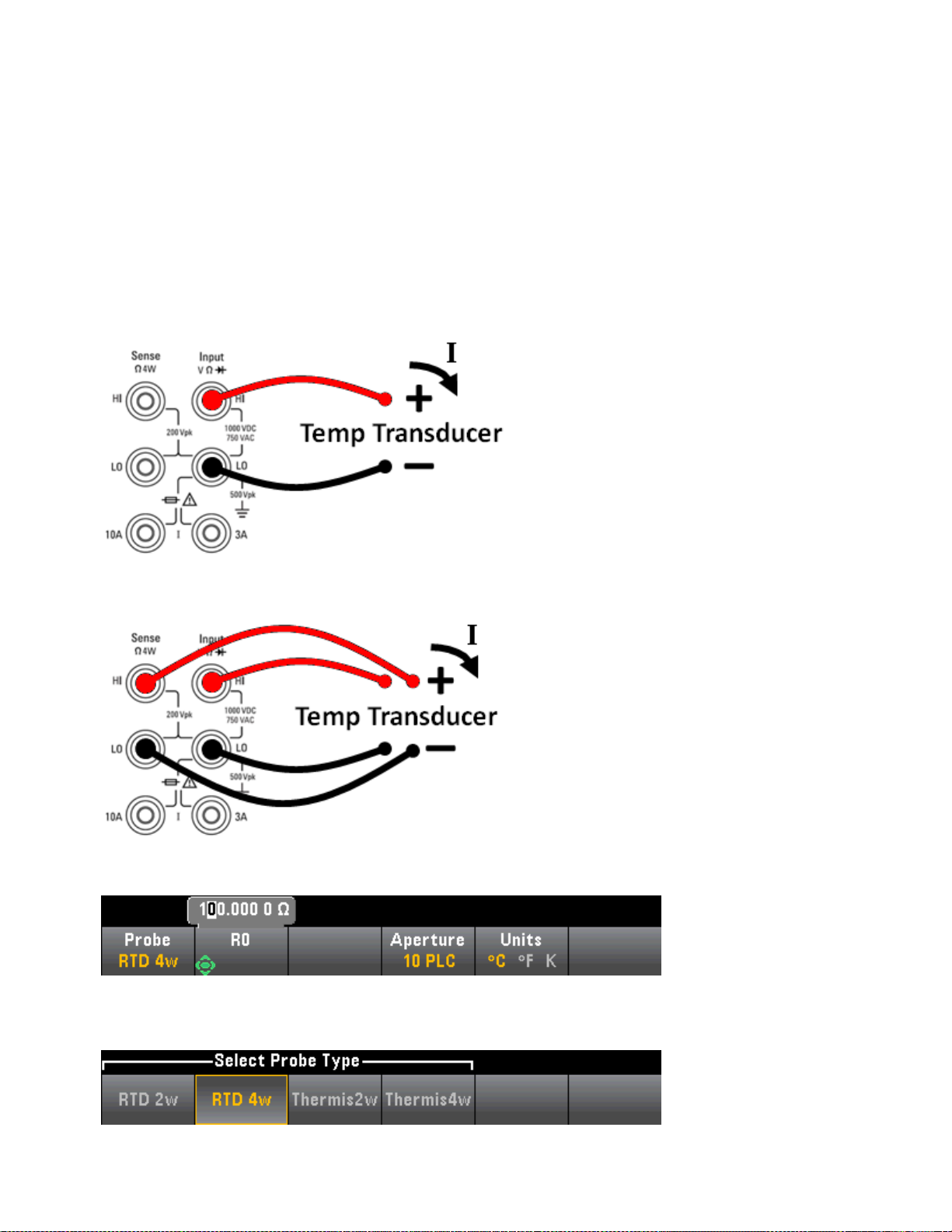
Features and Functions
Temperature (34460A and 34461A)
This topic applies only to 34460A/61 DMMs. For temperature measurements using the 34465A/70A, see
Temperature (34465A and 34470A).
This section describes how to configure 2-wire and 4-wire temperature measurements from the front
panel.
Step 1: Configure the test leads as shown.
2-wire Temperature:
4-wire Temperature:
Step 2: Press [Temp] on the front panel. The following menu appears.
Step 3: Press Probe and choose the probe type. If you choose to use an RTD, the menu will have a softkey
to specify the RTD's resistance at 0 degrees Celsius (R0).
Keysight TruevoltSeries Operating and Service Guide
69
Page 69
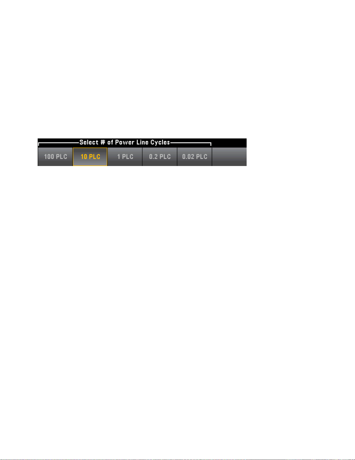
Features and Functions
Step 4: For 2-wire measurements, an Auto Zero softkey is available.
Auto Zero: Autozero provides the most accurate measurements, but requires additional time to perform
the zero measurement.With autozero enabled (On), the DMM internally measures the offset following
each measurement. It then subtracts that measurement from the preceding reading. Thisprevents offset
voltages present on the DMM’s input circuitry from affecting measurement accuracy. With autozero disabled (Off), the DMM measures the offset once and subtracts the offset from all subsequent measurements. The DMM takesa new offset measurement each time you change the function, range, or
integration time. ( There is no autozero setting for 4-wire measurements.)
Step 5: Press Aperture and choose the number of power-line cycles (PLCs) to use for the measurement.
Only 1, 10, and 100 PLC provide normal mode (line frequency noise) rejection. Selecting 100 PLC provides
the best noise rejection and resolution, but the slowest measurements:
Step 6: Use the Units softkey to display temperature in degrees Celsius, degrees Fahrenheit, or Kelvin.
70
Keysight TruevoltSeries Operating and Service Guide
Page 70

Features and Functions
Temperature (34465A and 34470A)
This topic applies only to 34465A/70 DMMs. For temperature measurements using the 34460A/61A, see
Temperature (34460A and 34461A).
This section describes how to configure temperature measurements from the front panel. Temperature
measurements require a temperature transducer probe. The supported probes are 2-wire and 4-wire RTDs,
2-wire and 4-wire thermistors (5 kΩ 44007 type, see Thermistor Requirements), and type E, J, K, N, R, or T
thermocouples.
This section describes general temperature measurement configuration information. For a
detailed tutorial on temperature measurements, refer to Keysight Application Note 290 Practical Tem-
perature Measurements available at www.keysight.com.
Step 1: Configure the test leads as shown.
2-wire Temperature:
4-wire Temperature:
Step 2: Press [Temp] on the front panel.
Step 3: The Aperture NPLC softkey is selected by default. Use the up/down arrow keys to specify integ-
ration time in power-line cycles (PLCs) to use for the measurement . 1, 10, and 100 PLC provide normal
mode (line frequency noise)rejection. Selecting 100 PLC provides the best noise rejection and resolution,
but the slowest measurements:
Keysight TruevoltSeries Operating and Service Guide
71
Page 71

Features and Functions
To set integration time precisely, instead of using PLCs, press Aperture Time and usethe left/right up/down arrow keys to specify integration time in seconds. For Aperture Time, you can specify from 200µs
(20 µs with the DIG option) to 1 s integration time (2 µs resolution):
Step 4: Use the Units softkey to display temperature in degrees Celsius, degrees Fahrenheit, or Kelvin.
Step 5: Press Probe Settings, the default probe settings are:
Step 6: To select another probe type, press Probe and press one of the softkeys:
Additional settings for each probe type are described in the sections below.
For the RTD 2w or RTD 4w Probe Type...
The RTD 2w or RTD 4w probe types allow you to set R0 and to enable/disable offset compensation and/or
the low-power mode:
R0: R
is the nominal resistance of an RTD at 0 °C. Default 100 Ω
0
OffstComp Enables or disables offset compensation. Offset compensation removes the effects of small dc
voltages in the circuit being measured. The technique involves taking the difference between two resistance measurements, one with the current source set to the normal value, and one with the current
source set to a lower value. Enabling Offset Compensation approximately doubles the reading time.
Low Power: Disables (Off) or enables (On) low power measurements. The low power mode sources less
test current per measurement range than is normally sourced for standard resistance measurements, to
reduce power dissipation and self-heating in the probe.
PressDone to return to the main temperature menu.
72
Keysight TruevoltSeries Operating and Service Guide
Page 72

Features and Functions
For the RTD 2w probe type, an additional Auto Zero setting is available:
Auto Zero: Autozero provides the most accurate measurements, but requires additional time to perform
the zero measurement.With autozero enabled (On), the DMM internally measures the offset following
each measurement. It then subtracts that measurement from the preceding reading. Thisprevents offset
voltages present on the DMM’s input circuitry from affecting measurement accuracy. With autozero disabled (Off), the DMM measures the offset once and subtracts the offset from all subsequent measurements. The DMM takesa new offset measurement each time you change the function, range, or
integration time. ( There is no autozero setting for 4-wire measurements.)
For the Thermis2w or Thermis4w Probe Type...
The Thermis2w or Thermis4w probe types allow you to enable/disable low power mode:
Low Power: Disables (Off) or enables (On) low power measurements. The low power mode sources less
test current per measurement range than is normally sourced for standard resistance measurements, to
reduce power dissipation and self-heating in the probe.
PressDone to return to the main temperature menu. For the Thermis2w probe type, an additional Auto
Zero setting is available:
Auto Zero: Autozero provides the most accurate measurements, but requires additional time to perform
the zero measurement.With autozero enabled (On), the DMM internally measures the offset following
each measurement. It then subtracts that measurement from the preceding reading. Thisprevents offset
voltages present on the DMM’s input circuitry from affecting measurement accuracy. With autozero disabled (Off), the DMM measures the offset once and subtracts the offset from all subsequent measurements. The DMM takesa new offset measurement each time you change the function, range, or
integration time. ( There is no autozero setting for 4-wire measurements.)
Thermistor Requirements
The DMM converts the measured thermistor resistance to temperature using the Steinhart-Hart thermistor equation:
1⁄T = A + B (Ln(R)) + C (Ln(R))
Where:
Keysight TruevoltSeries Operating and Service Guide
3
73
Page 73

Features and Functions
A, B, and C are constants provided by the thermistor manufacturer and derived from three
temperature test points.
R = Thermistor resistance in Ω.
T = Temperature in degrees K.
Important: Use only a 5 kΩ 44007-type thermistor. This type thermistor has constants of A = 1.285e-3, B
= 2.362e-4, C = 9.285e-8. Using an incorrect type of thermistor can result in errors greater than 20 °C for
a temperature being measured of 100 °C.
For a detailed tutorial on temperature measurements, refer to Keysight Application Note 290 Practical
Temperature Measurements available at www.keysight.com.
For the TCouple Probe Type...
The TCouple probe types allows these settings:
Type: Select the type of thermocouple. Supported types are J (default), K, E, T, N, or R
Reference: Thermocouple measurements require a reference junction temperature. You can input a
known fixed reference junction temperature (typically used for external reference junctions) or use the
internally measured temperature of the front terminals as the reference junction temperature. Select
internal or fixed reference.
Important: Since the internal reference temperature is the temperature of the front connections, use of
the rear connections with the selection of the internal reference junction will have an unknown error with
no specified performance and is not recommended.
Offset Adjust: Allows you to make minor temperature adjustments to correct for the differences between
the DMM internal temperature measurement of the front connection and the actual temperature of the
measurement terminals. When you select the internal reference junction, the internal temperature measurement of the front terminals plus the specified offset value is used as the reference junction temperature.
For example, if the measured internal temperature is +20.68 °C and the specified offset is +5 °C, the artificial cold junction mathematicsuses the sum of the two values. Keysight recommends that the offset be
left at 0 unless metrology has indicated otherwise.
Fixed Offset: When you select the external reference junction, you must specify the reference junction
temperature in degrees Celsius. Enter a value from -20°C to +80°C. Default: 0°C. For example, to set the
fixed reference temperature to +23.36 °C:
PressDone to return to the main temperature menu showing additional settings for thermocouple measurements:
74
Keysight TruevoltSeries Operating and Service Guide
Page 74

Features and Functions
Auto Zero: Autozero provides the most accurate measurements, but requires additional time to perform
the zero measurement.With autozero enabled (On), the DMM internally measures the offset following
each measurement. It then subtracts that measurement from the preceding reading. Thisprevents offset
voltages present on the DMM’s input circuitry from affecting measurement accuracy. With autozero disabled (Off), the DMM measures the offset once and subtracts the offset from all subsequent measurements. The DMM takesa new offset measurement each time you change the function, range, or
integration time. ( There is no autozero setting for 4-wire measurements.)
Open Check: Disables or enables the thermocouple check feature to verify that your thermocouples are
properly connected for measurements. When enabled, the instrument measures the resistance after each
thermocouple measurement to ensure a proper connection. If an open connection isdetected (greater
than 5kΩ on the 10kΩ range), the instrument reports an overload condition.
For more information about making temperature measurements refer to Keysight Application Note 290
Practical Temperature Measurements available at www.keysight.com.
Keysight TruevoltSeries Operating and Service Guide
75
Page 75

Features and Functions
Capacitance
This section describes how to configure capacitance measurements from the front panel.
Step 1: Configure the test leads as shown.
Step 2: Press on the front panel.
Step 3: To null–out the test lead capacitance:
l Disconnect the + and - test leads probe end from the test circuit, and leave open.
l
PressNull. The DMM will now subtract this null value from capacitance measurements.
Step 4: Press Range to select a range for the measurement. You can also use the [+], [-], and [Range]
keys on the front panel to select the range. (Auto (autorange) automatically selects the range for the meas-
urement based on the input. Autoranging is convenient, but it results in slower measurements than using
a manual range. Autoranging goes down a range at less than 10% of range and up a range at greater than
120% of range. For capacitance measurements only, when autorange is off, the instrument does not
report an overload for readings greater than 120% of range. Overload only occurs when the algorithm
times out because the applied capacitance is too large for the algorithm to measure. If you apply a DC
voltage or a short to the input terminals in capacitance measurement mode, the instrument reports an
overload.
76
Keysight TruevoltSeries Operating and Service Guide
Page 76

Features and Functions
Continuity
This section describes how to configure continuity tests from the front panel.
Step 1: Configure the test leads as shown.
Step 2: Press [Cont] on the front panel to open a menu where you can enable or disable the beeper for all
functions that use the beeper (limits, probe hold, diode, continuity, and errors).
Continuity measurements behave as follows:
≤ 10 Ω displays measured resistance and beeps (if beeper enabled)
10 Ω to 1.2 kΩ displays measured resistance without beeping
> 1.2 kΩ displays OPEN with no beep
Keysight TruevoltSeries Operating and Service Guide
77
Page 77

Features and Functions
Diode
This section describes how to configure diode tests from the front panel. The range and resolution are
fixed; the range is 10 VDC (with a 1 mA current source output).
Step 1: Configure the test leads as shown.
Step 2: Press on the front panel to open a menu that specifies whether the DMMwill beep to indicate
a successful diode test.
Diode measurements behave as follows:
0to5V voltage displayed on the front panel, and instrument beeps when signal transitions into the 0.3 to
0.8 V threshold (if beeping is enabled)
>5V the front panel displays OPEN, and SCPI returns 9.9E37
78
Keysight TruevoltSeries Operating and Service Guide
Page 78
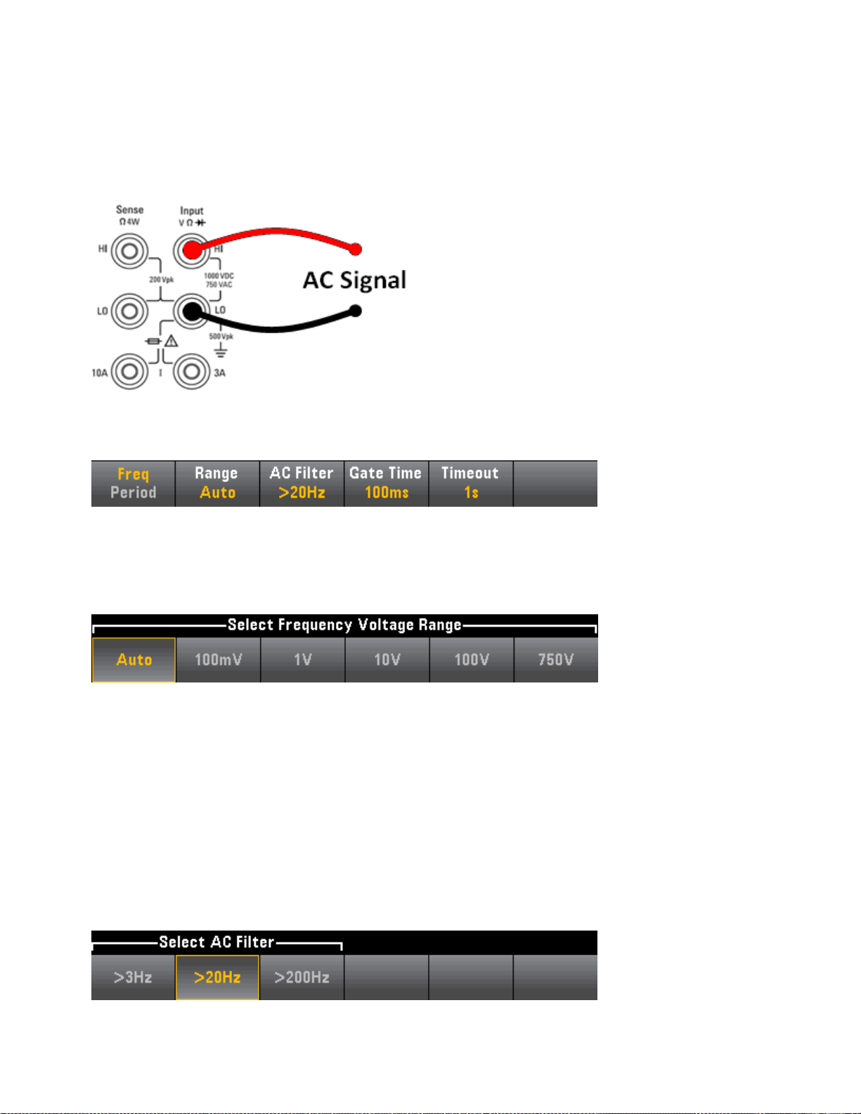
Features and Functions
Frequency and Period
This section describes how to configure frequency and period measurements from the front panel.
Step 1: Configure the test leads as shown.
Step 2: Press [Freq] on the front panel and then use the first softkey to choose either frequency or period
measurement.
Step 3: Press Range to select a range for the measurement. (Auto (autorange) automatically selects the
range for the measurement based on the input. Autoranging is convenient, but it results in slower measurements than using a manual range. Autoranging goes up a range at 120% of the present range, and
down a range below 10% of the present range.
Step 4: Press AC Filter and choose the filter for the measurement. The instrument usesthree different AC
filters that enable you either to optimize low frequency accuracy or to achieve faster AC settling times following a change in input signal amplitude.
The three filters are 3 Hz, 20 Hz, and 200 Hz, and you should generally select the highest frequency filter
whose frequency is less than that of the signal you are measuring, because higher frequency filters result
in faster measurements. For example, when measuring a signal between 20 and 200 Hz, use the 20 Hz filter.
If measurement speed is not an issue, choosing a lower frequency filter may result in quieter measurements, depending on the signal that you are measuring.
Keysight TruevoltSeries Operating and Service Guide
79
Page 79

Features and Functions
Step 5: Press Gate Time and choose the measurement aperture (integration time) of 1 ms (34465A/70A
only) 10 ms, 100 ms (default), or 1s.
Step 6: (34465A/70A only) Press Timeout to control how long the instrument waits before timing out on
a frequency or period measurement when no signal is present. When set to 1s, the instrument waits 1
second before timing out. When set to Auto, the wait time varies with AC filter bandwidth; for the faster
bandwidths, the instrument waits a shorter time before timing out and returning 0.0. This is advantageous
in manufacturing test systems where a DUT failure may result in no signal; in this case, the failure can be
detected sooner, speeding up test throughput.
For accurate displayed statistics of AC measurements in Front Panel mode, the default manual trigger delay
(
[Acquire] > Delay Man
) must be used.
80
Keysight TruevoltSeries Operating and Service Guide
Page 80

Features and Functions
Data Logging
The Data Log mode is standard on the 34465A and 34470A only, as is available only from the DMM's front
panel. Data Log mode provides a front–panel user interface that allows you to set up data logging into the
instrument’s non–volatile memory, or to internal/external file(s), without programming, and without a connection to a computer. Once you have finished collecting data, you can view it from the front panel, or you
can transfer the data to your computer. Data Log mode allows you to log a specified number of readings,
or readings acquired for a specified period of time, to instrument memory or to internal or external data
files.
To select Data Log mode, press [Acquire] Acquire > Data Log. You can then select the Sample Interval
(time between measurements - for example, 500 ms), Duration as either an amount of Time or a number of
Readings, whether to Start after a Delay or at a specific Time of Day, and whether to Log to Memory or Log
to File(s). After configuring the data logging parameters, press [Run/Stop]. Data logging will begin fol-
lowing the specified Delay or at the specified Time of Day.
Data Log mode can be used with the DC voltage, DC current, AC voltage, AC current, 2-wire and 4-wire
resistance, frequency, period, temperature, capacitance, and ratio measurement functions (diode and continuity are excluded). The maximum reading rate is 1000 readings/s and the maximum duration is100
hours resulting in a maximum number of readings of 360,000,000 to file. The number of readings you can
log to memory depends on the amount of instrument memory. With the MEM option, the limit is
2,000,000 readings; without the MEM option, the limit is50,000 readings. By default, data logging implements auto trigger. The level and external trigger sources are not supported for data logging.
Loss of data possible - local to remote transition clears instrument memory: When
data logging or digitizing to memory, if you access the instrument from remote (send a SCPI
or common command)* and then return to local (by pressing [Local]), the readings in
memory are cleared and the instrument returns to Continuous mode.
For data logging only, you can prevent this situation by data logging to a file instead of to
memory (see Data Log Mode for details). You can also prevent this from happening for data
logging or digitizing by taking steps to keep the instrument from being accessed from
remote. To prevent remote access, you may want to disconnect the LAN, GPIB, and USB
interface cables from the instrument before starting the measurements. To prevent remote
access via LAN, you can connect the instrument behind a router to minimize the possibility of
remote access. You can also disable the various I/O interfaces from the front panel menus
under [Utility] > I/O Config.
To view the status of a data logging or digitizing operation remotely, use the instrument’s
Web User Interface. The Web User Interface monitor does not set the instrument to remote.
*When accessed from remote, the instrument will continue data logging or digitizing to completion, and you can
retrieve the readings from remote.
Data Logging Overview
This section is a summary of the steps involved in setting up data logging. Detailed steps are described
below in Detailed Data Logging Steps.
Keysight TruevoltSeries Operating and Service Guide
81
Page 81

Features and Functions
1.
Select the measurement function and make connections to the DUT (see Measurements for details).
2. Select Data Log mode (press [Acquire] > Acquire > Data Log).
3.
Specify the sample interval (time between readings) for example, 20 ms.
4.
Specify the duration as amount of time or number of readings.
5.
Specify when to start data logging (delay or time of day). You can only use auto trigger (default) or single
trigger (press [Single])for data logging.
6.
Select whether to log data to memory or internal or external data file(s).
7. Press [Run/Stop] or [Single]. Data logging starts when the specified delay has elapsed or the time of day
occurs (specified in Step 5). Data logging will stop after the specified duration (time or number of readings)
has occurred or after you press [Run/Stop] again.
Detailed Data Logging Steps
Note: For more information, on any of the softkeys described below, such as the range of values for a par-
ticular setting, press and hold the softkey to display help for that softkey.
Step 1: Select the measurement function and make connections to the DUT (see Measurements for
details). For example, pressDCV and configure the test leads as shown.
Step 2: Press [Acquire] on the front panel to display these softkeys:
Pressthe Acquire softkey.
Pressthe Data Log softkey. The Data Log menu opens:
Step 3: Press Sample Interval and specify the time interval between samples (readings).
82
Keysight TruevoltSeries Operating and Service Guide
Page 82

Features and Functions
Note: You may see this message when configuring data logging: Sample interval is limited by meas-
urement settings. The measurement time is determined by the measurement function, NPLC, Aperture,
Autorange, Autozero, Offset Compensation, AC Filter, TC Open Check, and Gate Time. The data logging
Sample Interval cannot be less than the measurement time. You can shorten the measurement time by
selecting less integration time, selecting a fixed range, and so on.
Step 4: Press the Duration softkey to specify the length of time to log data, or, press Duration again to
specify the total number of readings to log.
Step 5: Press Start to specify when to start data logging. You can select:
l
Start Delay - Starts data logging after a specified time delay. Specified in HH.MM.SS format.
l
Start Time of Day - Starts data logging at a specified time of day. Specified in HH.MM.SS format.
Using the time of day requires that the instrument’s real-time clock is properly set. To set the clock,
press [Shift] > [Utility] > System Setup > Date/Time.
You cannot configure a trigger source when data logging. You can only use auto trigger (selec-
ted by default) or, when ready to initiate data logging, you can cause a single trigger (by pressing
[Single]). The effect is the same, as you only need one auto trigger or single trigger event to enable data
logging.
Step 6: Press Log To > Log To Memory or Log To Files to specify whether the data logging results will be
stored in volatile memory for display or written to one or more internal/external files.
l When data logging to memory, the data is volatile (not remaining during power off) but can be saved
to an internal or external file after data logging iscomplete (see Step 7 below). The number of readings
you can store in memory depends on the amount of instrument memory. With the MEM option, the
limit is 2,000,000 readings. Without the MEM option, the limit is 50,000 readings.
Keysight TruevoltSeries Operating and Service Guide
83
Page 83

Features and Functions
l
When data logging to file(s), Browse to an internal or external path and specify a File Name. If more
than one file needs to be created to hold the data, the second file name will be appended with _00001,
the third file name with _00002, and so on. When data logging to files, the maximum number of readings is 360,000,000.
When Add Date is On, the data logging start date and time is appended to the file name using the
format:
_YYYYMMDD_HHMMSS
For example, for a file named Data 1, the result will be similar to: Data 1_20140720_032542.
PressOptions to to configure reading storage options:
Rows/File - Specifies the maximum number of rows or readings to be written to a file. For Max, the
limit is the number of bytes allowed by the file system (232= 4.294967296 GBytes). This represents
approximately 252 M readings with Metadata Off, or 159 M readings with Metadata On. For 1M, the
limit is 1,000,000 rows in the resulting file. This allows you to accommodate common spreadsheet,
database and data analysis programs that have limitations of 1 million rows per file.
Metadata - Enables reading number, time stamp of first reading, and sample interval (if available) in
the file.
Separator - Specifies the character (Comma, Tab, or Semicolon) to use for separating the information
on each row.
When finished configuring reading storage, press Done > Done to return to the main data logging
menu.
84
Keysight TruevoltSeries Operating and Service Guide
Page 84

Features and Functions
Step 7: Press [Run/Stop] or [Single]. Data logging starts when the specified delay has elapsed or the time
of day occurs (specified in Step 5). Data logging will stop after the specified duration (time or number of
readings) has occurred or after you press [Run/Stop] again.
When data logging is complete:
l When data logging to file(s), theinstrumentsavesthefile(s)with thespecifiednameandpath.
l When data logging to memory, you can now save the readings from the main data log menu by press-
ing Save Readings.
You can then Browse to an internal or external path and specify a File Name. You can also specify
reading storage Options asdescribed above in Step 6.
Trend Chart for Data Logging
The Trend Chart is particularly useful for viewing data logging measurements. See Trend Chart (Digitize
and Data Log Modes) for details.
Keysight TruevoltSeries Operating and Service Guide
85
Page 85
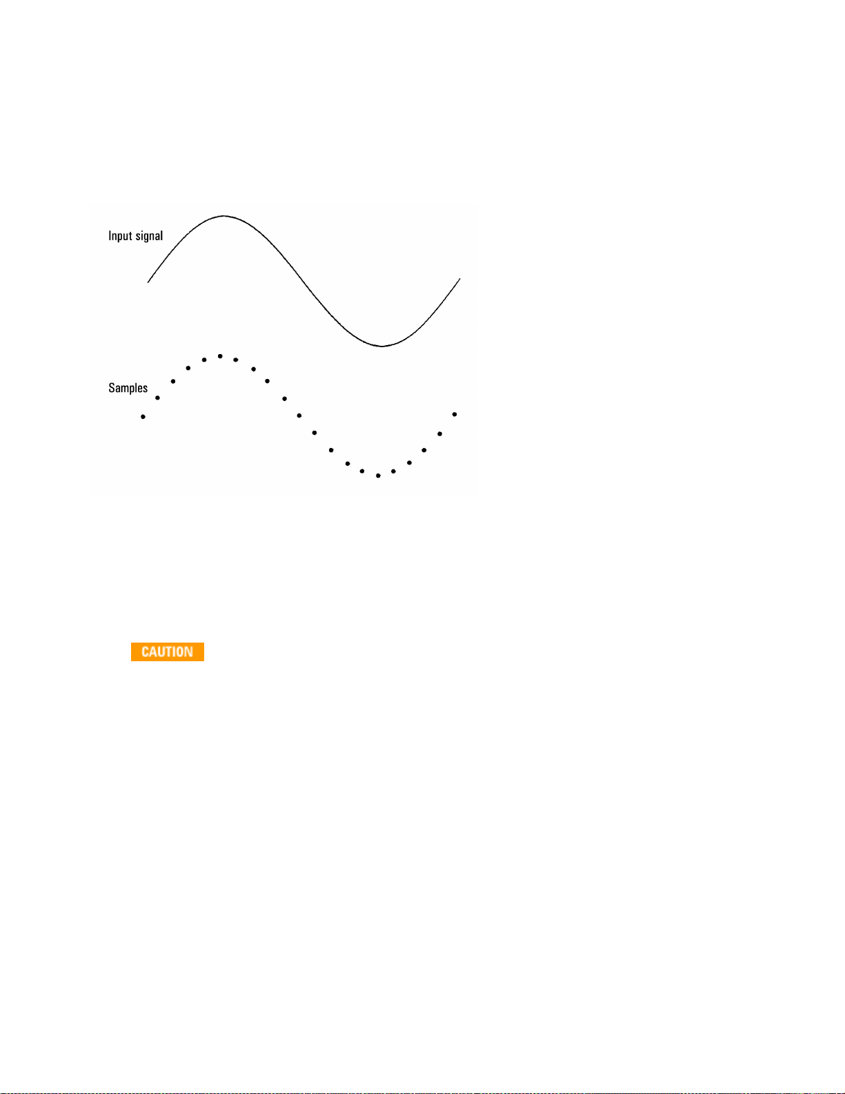
Features and Functions
Digitizing
The digitizing feature (applies only to the 34465A/70A with the DIG option) provides a front–panel user
interface that allows you to quickly set up digitized measurements. Digitizing isthe process of converting a
continuous analog signal, such as a sine wave, into a series of discrete samples (readings):
See Digitizing Measurements for a tutorial on digitizing and more information on samples rates vs. input fre-
quencies.
The DMM digitizes by sampling the input signal using either the DCV function (default) or the DCI function
with autorange and autozero disabled.
Loss of data possible - local to remote transition clears instrument memory: When
data logging or digitizing to memory, if you access the instrument from remote (send a SCPI
or common command)* and then return to local (by pressing [Local]), the readings in
memory are cleared and the instrument returns to Continuous mode.
For data logging only, you can prevent this situation by data logging to a file instead of to
memory (see Data Log Mode for details). You can also prevent this from happening for data
logging or digitizing by taking steps to keep the instrument from being accessed from
remote. To prevent remote access, you may want to disconnect the LAN, GPIB, and USB
interface cables from the instrument before starting the measurements. To prevent remote
access via LAN, you can connect the instrument behind a router to minimize the possibility of
remote access. You can also disable the various I/O interfaces from the front panel menus
under [Utility] > I/O Config.
To view the status of a data logging or digitizing operation remotely, use the instrument’s
Web User Interface. The Web User Interface monitor does not set the instrument to remote.
86
Keysight TruevoltSeries Operating and Service Guide
Page 86

Features and Functions
*When accessed from remote, the instrument will continue data logging or digitizing to completion, and you can
retrieve the readings from remote.
Digitizing Overview
This section is a summary of the steps involved in setting up digitizing. Detailed steps are described below
in Detailed Digitizing Steps.
1.
Select DCV or DCI measurements and connect to the DUT.
2. Select Digitize mode (press [Acquire] > Acquire > Digitize).
3.
Specify the sample rate (for example, 50 kHz) or sample interval (for example, 20 µS).
4.
Specify the duration as amount of time or number of readings.
5.
Select trigger source (Auto, Ext, or Level).
a.
For external, specify polarity.
b.
For level, use Range +/- to select fixed range, then specify threshold and polarity.
6.
Specify delay time or use auto.
7.
Optional: If using the level or external trigger source, specify a pretrigger count (number of readings to
store before the trigger event occurs).
8. Press [Run/Stop]. Digitizing starts when the trigger event occurs and stops after duration or when you
press [Run/Stop] again.
9.
Save the digitized data to a file.
10.
Optional: select trend chart to view digitized data.
The histogram and statistics functions can be used when digitizing. However, this data will not
be updated until digitizing iscomplete.
Detailed Digitizing Steps
Step 1: To digitize DC voltage, press DCV and configure the test leads as shown.
To digitize DC current, press DCI and configure the test leads as shown.
Keysight TruevoltSeries Operating and Service Guide
87
Page 87

Features and Functions
On the 34461A/65A/70A, you can also configure the measurement using the 10 A terminal, which is
recommended when measuring current above 1 A:
Step 2: Press [Acquire] on the front panel and then press the Acquire softkey:
Pressthe Digitize softkey:
Step 3: The Digitize menu opens:
With Sample Rate selected, use the up/down arrow keys to select a sample rate in samples per second
(Hz), or press the Sample Rate softkey to specify a sample interval (time between samples):
Step 4: Press the Duration softkey to specify the length of time to digitize:
or, press Duration again to specify the total number of samples to digitize:
88
Keysight TruevoltSeries Operating and Service Guide
Page 88

Features and Functions
Step 5: Press Trigger Settings to view or change the trigger source. By default, the trigger source is set to
auto. You can also select external and level triggering when digitizing.
PressTrg Source and select one of three trigger sources:
Auto - the instrument automatically triggers immediately after you press [Run/Stop] or [Single].
Step 5a Configure external triggering: After pressing Ext, this menu appears:
Ext - the instrument triggers when an edge of the appropriate slope arrives at the rear-panel Ext Trig con-
nector. You can specify the slope on the softkey menu that appears when Trg Src is set to Ext. To select
external triggering, press Ext, and select either Pos or Neg slope:
Step 5b Select level trigger: Level - (34465A/70A with DIG option only) the instrument issues one trig-
ger when the specified measurement threshold with the specified positive or negative slope occurs. To
select level triggering, press Level and specify the level threshold and Pos or Neg slope:
Select the expected measurement range using the [Range] [+] and [-] keys before setting the
level trigger voltage or current.
Step 6: Specify delay time
Specify the delay that occurs prior to digitizing. This delay is inserted once, after the trigger event occurs,
and before digitizing begins. This can be automatic (the instrument chooses the delay based on the instrument’s settling time) or manual (you specify the delay time).
Step 7: (Optional) Specify pretrigger count.
When an External or Level Trigger Source is used, you can specify a pretrigger count. After specifying a pretrigger count, readings are taken and held in a buffer while waiting for the trigger event to occur. When the
trigger event occurs, the buffered readings are transferred to reading memory and the remaining readings
Keysight TruevoltSeries Operating and Service Guide
89
Page 89

Features and Functions
are recorded as usual. If the trigger event occurs before Pretrigger Count readings have been taken, the
trigger event will still take effect and digitizing will complete without having taken all of the pretrigger readings. The Pretrigger Count is limited to one less than the total number of readings specified to be taken by
the Duration setting.
Step 8: Press [Run/Stop] to start the digitizing process. Digitizing will begin when the specified trigger
event occurs and after the specified delay has elapsed. • Digitizing is displayed at the top of the display
while digitizing; when finished, Digitize Stopped is displayed.
Step 9: All readings taken during digitizing are saved in volatile memory, when digitizing is finished, press
the Save Readings softkey to specify a file location and save the readings.
Step 10: (Optional) Press Display > Display Trend to view the trend chart. The Trend Chart is particularly
useful for viewing and analyzing digitized measurements. Xand Y cursors (shown below), tracking cursors,
pan control, and zoom allow you to analyze digitized data. See Trend Chart (Digitize and Data Log Modes)
for details.
90
Keysight TruevoltSeries Operating and Service Guide
Page 90

Features and Functions
Level Triggering
Level triggering is available only on the 34465A/70A with the DIG option. Level triggering allows you to
trigger measurements at some defined point on the input signal, such aswhen the signal crosses zero
volts or when it reaches the midpoint of its positive or negative peak amplitude. For example, this graphic
shows sampling beginning as the input signal crosses 0V with a positive slope:
About Level Trigger
Level triggering is available for these measurement functions:
l DC voltage and DC current
l AC voltage and AC current
l 2-wire and 4-wire resistance with offset compensation off, and low power off
l Temperature, RTD or thermistor sensors only
l Frequency and period
The level trigger is edge-sensitive. That is, the instrument must detect a change in the quantity being measured from one side of the level setting to the other side (direction controlled by Slope setting). For
example, if the Slope is positive, then the quantity being measured must first reach a value below the set
level before a trigger event can be detected.
Level trigger performance is not uniform. Its accuracy, latency, and sensitivity are dependent on other
DMM features. These dependencies vary by measurement function as described below.
DC voltage, DC current, and 2-wire resistance considerations
These measurement functions can use a fast-response detector built into the hardware for fixed-range
measurements. For lowest latency and highest sensitivity, use a fixed range when using level trigger.
However, trigger level accuracy is reduced when the hardware detector is used.
To increase trigger level accuracy and reduce sensitivity (avoid false triggers due to noise), use autorange:
l When auto-range isenabled, trigger level accuracy is increased, latency is increased, and sensitivity is
decreased as the aperture or NPLC setting is increased.
Keysight TruevoltSeries Operating and Service Guide
91
Page 91

Features and Functions
l When auto-range isenabled, trigger level accuracy is increased, latency is increased, and sensitivity is
decreased if autozero is enabled.
l When auto-range isenabled, range changes may be made while waiting for the trigger crossing which
can cause additional latency/uncertainty.
4-wire resistance and temperature considerations
l Trigger level accuracy is increased, latency is increased, and sensitivity is decreased as aperture or
NPLC is increased.
l Fixed range (only available for resistance) eliminates uncertainties (due to range change) in trigger
latency.
AC voltage and AC current considerations
l Trigger latency is increased, and sensitivity is decreased as filter bandwidth is increased.
l Trigger latency can be controlled by trigger delay setting.
l Fixed range eliminates uncertainties (due to range change) in trigger latency.
l Autorange uncertainties become worse as filter bandwidth is increased.
Frequency and period considerations
l Trigger level accuracy is increased, latency is increased, and sensitivity is decreased as gate time is
increased.
l Fixed voltage range eliminates uncertainties (due to range change) in trigger latency.
92
Keysight TruevoltSeries Operating and Service Guide
Page 92

Features and Functions
Secondary Measurements
Most measurement functions allow you to select and display a secondary measurement function. Secondary measurements can be displayed in the Number and Bar Meter displays only. For example, a thermistor temperature measurement (primary) and the resistance measurement made on the thermistor
(secondary) are shown below:
To select a secondary measurement from the front panel, first select the primary measurement function
and then press Display:
Press2nd Meas and select the secondary measurement.
The primary measurement functions and their associated secondary measurements for each DMM model
are:
Primary Measurement Function 34460A/61A Secondary
Measurement Function
DCV ACV
ACV Frequency DCV1, Frequency, Pre-Math
2-Wire, 4-Wire Resistance Pre-Math
DCI ACI
ACI Frequency DCI1, Frequency, Pre-Math
Frequency Period Period, ACV, Pre-Math
Period Frequency Frequency, ACV, Pre-Math
Temperature Sensor Sensor, Pre-Math
Ratio Input/Ref Input/Ref, Pre-Math
Capacitance Pre-Math
Cont None
Diode None
1
1
34465A/70A Secondary
Measurement Function
ACV1, Peak, Pre-Math
ACI1, Peak, Pre-Math
Keysight TruevoltSeries Operating and Service Guide
93
Page 93

Features and Functions
Where:
l Pre-Math - The measurement value before any math operations are done (including NULL).
l Sensor - The raw sensor value; ohms for thermistor/RTD, volts for thermocouple (thermocouple meas-
urements apply to the 34465A and 34470A only).
l Input/Ref - The DC signal voltage and the DC reference voltage measurements.
l Peak - Displays a running history of the minimum peak, maximum peak, and peak-to-peak values of the
input signal. Peak measurements are high-speed (16 µs effective aperture) and are different from the Min,
Max, and Peak-to-Peak values gathered in Statistics.
1
After making one or more primary measurements for approximately 4 seconds, the DMM makes one
secondary measurement.
For the Peak secondary measurement, the Clear Peaks softkey allows you to clear the accumulated history of the peak-to-peak function (resets the record of peak values).
94
Keysight TruevoltSeries Operating and Service Guide
Page 94

Features and Functions
Triggering and Readings
The trigger model and large reading memory on the Truevolt Series DMMs provide versatile capabilities for
a wide variety of applications.
Instrument trigger model
Acquiring measurements on the DMM isdone as the result of triggering. This section describes how to configure triggering for the Continuous measurement mode. For the 34465A/70A, refer to Digitizing and Data
Logging for information on triggering in those measurement modes.
For the 34460A/61A, pressing [Acquire] opens the following menu:
For the 34465A/70A, pressing [Acquire] opens the following menu:
PressTrigger Settings to open the following menu:
The menus above allow you to configure measurement triggering, and you can also use the VMC Out
softkey to set the edge slope of the VM Comp (voltmeter complete) output on the instrument's rear
panel. Thisconnector issuesa signal whenever the voltmeter finishes taking a measurement to allow you
to signal other devices in a measurement system.
For accurate displayed statistics of AC measurements in Front Panel mode, the default manual trigger delay
(
[Acquire] > Delay Man
The (Trg Src) menu allows you to select one of these trigger sources:
) must be used.
Auto - the instrument continuously takes measurements, automatically issuing a new trigger as soon as a
measurement is completed.
Single - the instrument issues one trigger each time the front panel [Single] key is pressed.
Keysight TruevoltSeries Operating and Service Guide
95
Page 95

Features and Functions
Ext - (Ext requires LAN option on 34460A) the instrument issues one trigger each time an edge of the
appropriate slope arrivesat the rear-panel Ext Trig connector. You can specify the slope on the softkey
menu that appears when Trg Src is set to Ext.
Level - (34465A/70A with DIG option only) the instrument issues one trigger when the specified meas-
urement threshold with the specified positive or negative slope occurs.
In the Single, Ext, and Level modes, you can specify the number of samples to be taken per trigger by
using the Samples/Trigger softkey. The Single and Ext modes can both buffer up to one trigger, meaning
that if you press [Single] or receive an external trigger while a series of measurements is in progress, the
instrument will finish that seriesof measurements and then immediately launch a new series of measurements based on the trigger.
If multiple [Single] or external triggers are issued during a series of measurements, all triggers received
after the first are discarded.
The [Acquire] menu also configures the delay that occurs before each measurement is taken, regardless
of the trigger mode (Auto, Single, or Ext). This may be either automatic (the delay isbased on the DMM’s
settling time) or manual (you specify the delay time).
Finally, note the [Run/Stop] and [Single] keys on the front panel. In Auto trigger mode, pressing [Run-
/Stop] stops and resumes measurements, and pressing [Single] switches the instrument to single trigger
mode. In the Single and Ext modes, pressing [Run/Stop] stops readings if they are in progress, or switches
the mode to Auto if readings are stopped.
96
Keysight TruevoltSeries Operating and Service Guide
Page 96

Features and Functions
Trigger delay and multiple samples
The instrument inserts a trigger delay between the occurrence of a trigger and the first measurement.
When Auto is used (Delay Auto softkey), the instrument automatically determines the delay based on
function, range and integration time. See Automatic Trigger Delays for further information. However, you
may need to manually set a delay (Delay Man softkey) longer than the automatic delay to allow the input
to settle before pacing a burst of measurements, for measurements with long cables, or for measurements
of high capacitance or high impedance signals.
If you have configured the instrument for more than one sample per trigger (Samples/Trigger softkey), in
all cases, the first sample is taken one trigger delay time after the trigger occurs. Beyond that, sample timing depends on whether you select immediate (Sample Immediate softkey , default) or timer (Sample
Timer softkey) as described below.
l
Sample Immediate - The first sample starts one trigger delay time after the trigger, and then the trigger
delay time is inserted between successive samples:
In this configuration, the sample timing is not deterministic because the delay time is inserted
after each sample completes. The actual time required to take each sample depends on the
integration time and autoranging time.
l
Sample Timer - The first sample starts one trigger delay time after the trigger. The second sample starts
one sample interval after the start of the first sample, and so on:
In this configuration, the sample timing is deterministic because the start of each sample is
determined by the specified sample interval (the trigger delay affects only the start of the first
sample). Integration time and autoranging affect the sampling time for each sample, but not
the sample interval. Periodic sampling continues until the sample count (set with the
Samples/Trig softkey) is satisfied.
Keysight TruevoltSeries Operating and Service Guide
97
Page 97

Features and Functions
From the front panel, the instrument prevents you from specifying a sample timer that is
shorter than the time required to make measurements based on the present function, range,
and integration time.
Storing and clearing readings
You can store up to 1,000 measurements in the reading memory of the 34460A, 10,000 measurements on
the 34461A, 50,000 measurements on the 34465A/70A (without the MEM option), or 2,000,000 measurements on the 34465A/70A (with the MEM option). Readings are stored in a first-in, first-out (FIFO) buf-
fer; when reading memory is full, the oldest readings are lost as newer readings are taken.
In Local (front panel) mode, the instrument collects readings, statistics, trend chart and histogram information in the background, so if you select any of those options, the data is ready for viewing. In Remote
(SCPI) mode, the instrument does not collect this information by default.
Changing the instrument from Local to Remote doesNOT clear any readings in memory. Changing the
instrument from Remote to Local DOEs clear any readings in memory.
In general, you turn the reading of measurements on and off by pressing [Run/Stop], as described above.
You can also take one reading or a specified number of readings by pressing [Single].
To save readings, press[Acquire] > Save Readings. Then use the menu that appears to configure the location where you want to save the readings:
See Utility Menu - Manage Files for details.
For the 34460A/61A only, press Save Readings to save the readings in memory to a file.
For the 34465A/70A only, press Options to configure reading storage options:
Rows/File - Specifies the maximum number of rows or readings to be written to a file.
l
For Max, the limit is the number of bytes allowed by the file system (232= 4.294967296 GBytes). This
represents approximately 252 M readings with Metadata Off, or 159 M readings with Metadata On.
l
For 1M, the limit is 1,000,000 rows in the resulting file. This allows you to accommodate common
spreadsheet, database and data analysis programs that have limitations of 1 million rows per file.
Metadata - Enables reading number, time stamp of first reading, and sample interval (if available) in the
file.
Separator - Specifies the character (Comma, Tab, or Semicolon) to use for separating the information on
each row.
When finished configuring reading storage, press Done > Save Readings to save the readings in memory
to a file.
98
Keysight TruevoltSeries Operating and Service Guide
Page 98

Clearing Reading Memory
The following actions clear reading memory:
l Changing the measurement function
l
Pressing any Clear Readings softkey
l Transitioning in or out of Probe Hold
l Changing temperature units
l Changing any dB/dBm parameters
l Changing any histogram binning parameter
Features and Functions
l Changing the temperature probe or R
l Recalling a stored state
l Calibrating the instrument
l Switching between 3 A and 10 A inputs
l Changing the position of the Front/Rear switch
l Transferring from Remote to Local mode
l Turning Null on or off or changing the Null value
0
These actions do not clear reading memory:
l Changing measurement parameters, such asrange and aperture.
l Turning limits on or off, or adjusting limit values
l
Pressing [Run/Stop] in front panel auto trigger mode
l
Changing the trend chart Recent/All softkey (34461A/65A/70A only)
l Changing samples per trigger or trigger delay
l Changing display modes
l
Changing the VM Comp output polarity
l Changing the digit mask
l Changing the histogram, bar meter, or trend chart scale
l Changing user preferences
l Executing self-test
Keysight TruevoltSeries Operating and Service Guide
99
Page 99

Features and Functions
Probe Hold
Because probing small areas requires careful concentration, it isoften difficult to read the instrument display while taking measurements. Therefore, the instrument includes a front panel [Probe Hold] key that
allows you to take readings without viewing the display. You can generate up to eight readings and hold
them on the display for later viewing. These readings may be of different measurement types and you may
clear displayed readings at any time.
In Probe Hold mode, the instrument optimizes measurement settings to allow reliable detection of stable
signals (these settings are restored to their original values when you exit Probe Hold.) When you probe a
signal, the instrument beeps (if the beeper is enabled)and automatically records a measurement when it
finds a seriesof stable readings. You may take additional readings without pressing [Probe Hold] again.
PressRemove Last to remove the last reading from the list. Press Clear List to remove all readings from
the list.
Because the Probe Hold display is optimized for the Probe Hold readings, you may not combine it with
other display modes, such as histogram, bar graph, trend chart, or statistics.
Probe Hold is a front panel only function. Readings recorded in Probe Hold mode cannot be accessed
from remote. You can, however, take a screen capture of the probe hold display, see Utility Menu - Man-
age Files for details.
100
Keysight TruevoltSeries Operating and Service Guide
Page 100

Math - Introduction
The [Math] key is the shifted [Null]:
These math functions are available for the 34460A/61A:
l Null
l dB/dBm Scaling
l Statistics
l Limits
These math functions are available for the 34465A/70A:
Features and Functions
l Null
l Smoothing Filter
l Scaling
l Statistics
l Limits
Keysight TruevoltSeries Operating and Service Guide
101
 Loading...