

Page 1

Keysight PXA Signal Analyzer
Option EXM
External Mixing Upgrade Kit
Notice: This document contains references to Agilent.
Please note that Agilent’s Test and Measurement business has become Keysight Technologies. For more information, go to www.keysight.com.
Installation Note
Part Number N9030-90058
Printed in USA August 2014
Page 2

Notice.
The information contained in this document is subject to change without notice.
Keysight Technologies mak
limited to, the implied warranties of merchantability and fitness for a particular purpose. Keysight
Technologies shall not be liable for errors contained herein or for incidental or consequential damages
in connection with the furnishing, performance, or use of this material.
es no warranty of any kind with regard to this material, including but not
© Copyright 2010 - 2014 Keysight Technologies, Inc.
Page 3

Option EXM, External Mixing Upgrade Kit
Option EXM, External Mixing Upgrade Kit
Products Affected: PXA N9030A
Serial Numbers: US/MY/SG51160000 and above
(Options 543, 544, and 550)
US/MY/SG51380000 and above
(Options 503, 508, 513, and 526)
To Be Performed By: (X) Agilent Service Center
(X) Personnel Qualified by Agilent
( ) Customer
Estimated Installation Time:
Estimated Adjustment Time:
Estimated Verification Time:
a. To ensure that these newly installed options are functioning properly, the procedure that follows
includes the requirement of performing certain adjustments and performance verification tests.
However, the completion of these tests does not guarantee that the instrument meets all advertised
specifications.
1.5 Hours
1.0 Hours
4.0 Hours
a
a
Software and test equipment is required for making adjustments and for performance verification
testing.
Information on how to obtain this software can be found at:
www.agilent.com/find/calibrationsoftware
While Agilent does re commend that a full calibration be performed after the instal lation of this
upgrade, the end user must ultimately determine whether they want this service or not. If a full
calibration is required, arrangements regarding the level of calibration must be made between the end
user and the calibration provider.
NOTE Option EXM requires instrument software A.10.00 or later. The latest revision of
the analyzer software may be downloaded from:
http://www.agilent.com/find/xseries_software
Installation Note N9030-90058 3
Page 4

Option EXM, External Mixing Upgrade Kit
Introduction
This kit includes parts to upgrade a PXA signal analyzer with frequency range option 503, 508, 513,
or 526 and serial number US/MY/SG51380000 or later or with frequency range option 543, 544, or
550 and serial number US/MY/SG51160000 or later to add option EXM, External Mixing. This kit
includes parts to upgrade a PXA regardle ss of fr equency ra nge optio n instal led. As a result , some parts
included in this kit will not be needed for upgrading some analyzers.
In addition to installing the hardware to support option EXM, licenses for the following options will
also be installed:
• N9030A-EXM, External Mixing
• Licenses for core instrument software enhancements. For a list of these enhancements see:
http://www.agilent.com/find/N9030AK-R2C
4 Installation Note N9030-90058
Page 5

Installation Kit Parts List
Option EXM, External Mixing Upgrade Kit
Quantity
Description Agilent Part
Number
1 Adapter- Coaxial Straight Female-SMA to Female-SMA, 50 1250-1666
1 Washer, Lock, Internal Tooth, ¼ inch 2190-0067
1 Nut-Hex-Double-Chamfer 1/4-36-THD.125-IN-THK, Stainless Steel 2950-0223
1 50 Ohm Termination, SMA male 1810-0118
1 Opt EXM Cable Kit with Wire Markers (includes two versions of
N9030-60014
cable W30, listed below)
1 Cable Assembly, External Mixing, Front Panel (W29) N9020-20166
1 Cable Assembly, uW Front End to W29 (W17) (for use in RF and
N9020-20132
microwave analyzers)
1 Cable Assembly, mmW Front End to W29 (W17) (for use in
N9020-20167
millimeter wave analyzers)
1 Cable Assembly, Coaxial 275 mm LG (W30) (for use in millimeter
wave analyzers)
1 Cable Assembly, Coaxial 350 mm LG (W30) (for use in RF and
microwave analyzers)
8120-2025
labeled ‘903’ and ‘13’
8120-2027
labeled ‘903’ and ‘13’
a
with ends
a
with ends
1 Label, External Mixing N9030-80014
1 Label, Warning N9030-80018
5 Cable Ties 1400-0249
1 Entitlement Certificate 5964-5178
1 Entitlement Certificate Envelope 5967-7169
1 Installation Note This note
a. This cable is included in the Opt EXM Cable Kit with Wire Markers, p/n N9030-60014.
Installation Note N9030-90058 5
Page 6

Option EXM, External Mixing Upgrade Kit
Tools Required
❏ T-10 TORX Driver
❏ T-20 TORX Driver
❏ 5/16-inch torque wrench
❏ ¼-inch open-end wrench
❏ Diagonal cutters
❏ Agilent Calibration and Adjustment Software, N7814A (revision E.08.00 or later)
❏ Test equipment and computer supported by the X- Series Performance Tests and Adjustment
Software
❏ PXA Signal Analyzer Service Guide. This manual is available as:
— N9030A Option OBW or
— Agilent part number N9030-90030
❏ Microsoft Windows based personal computer with internet access and USB port
❏ USB storage device with > 2 GB free memory
Initial Instrument Functionality Check
Power on the instrument and allow the instrument to boot up. Run an alignment and display the
measurement screen. (The instrument will probably display a spectrum analyzer screen and you will
see the instrument sweeping.)
There should be no alignment failures. If there are failures, investigate and fix the problem before
continuing.
WARNING Before you disassemble the instrument, turn the power switch to Standby.
After the instrument has completely shut down, unplug the instrument.
Failure to unplug the instrument can result in personal injury.
CAUTION Electrostatic discharge (ESD) can damage or destroy electronic components. All
work on electronic assemblies should be performed at a static-safe workstation.
Refer to the documentation that pertains to your instrument for information about
static-safe workstations and ordering static-safe accessories.
6 Installation Note N9030-90058
Page 7

Option EXM, External Mixing Upgrade Kit
Installation Procedure
1. Connect a power cord to the analyzer and turn on the analyzer.
2. After the analyzer has completed turning on, press
System, Show, System. Make note of the
following information from the Show System screen:
Product Number: _____________
Serial Number: ______________
Instrument S/W Revision: ______________
3. Check for the presence of one of the following frequency range options listed below in the Show
System. Put a check mark or “X” after the frequency range option listed below that appears in the
Show System menu.
N9030A-503_____
N9030A-508_____
N9030A-513_____
N9030A-526_____
N9030A-543_____
N9030A-544_____
N9030A-550_____
4. On the analyzer, press
System, Show, Hardware. Note the Part #, Matl Rev, Rev, OF Rev, and
Hw Id of the Front End in the table below.
Assembly Name Part # Matl Rev Rev OF Rev Hw Id
Front End
5. If the analyzer is equipped with any of the following frequency range options (refer to the data in
step 3 above):
N9030A-503
N9030A-508
N9030A-513
N9030A-526
And the part number of the Front End is one of the following:
N9020-60050
do not proceed with the installation of this upgrade kit.
An RF or microwave PXA with the N9020-60050 Front End assembly installed is not compatible
with Opt EXM. In this case, you should instead order N9030AK-HL6, which includes a new,
EXM-compatible, Front End Assembly.
Installation Note N9030-90058 7
Page 8

Option EXM, External Mixing Upgrade Kit
Analyzer Disassembly
CAUTION If the instrument is placed on its face during any of the following procedures, be
sure to use a soft surface or soft cloth to avoid damage to the front panel, keys, or
input connector.
NOTE Make sure any adapters on the front panel are removed.
1. Disconnect the instrument from ac power.
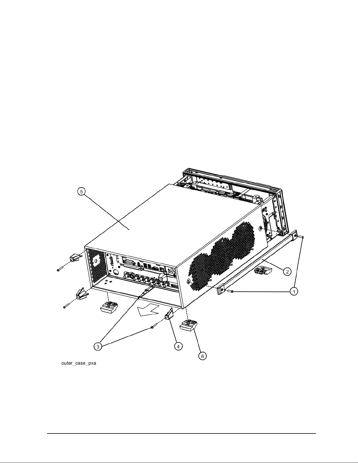
2. Refer to Figure 1. Using the T-20 driver, remove the 4 screws (1) (two on each side) that attach
the handle strap (2) on each side of the instrument.
3. Remove the four key locks from the instrument four bottom feet.
4. Remove the four instrument bottom feet (6).
5. Using the T-20 drive r, remove the four screws ( inclu ding wash ers) (3) t hat hol d the re ar fee t (4)
in place.
6. Pull the instrument cover (5) off towards the rear of the instrument.
8 Installation Note N9030-90058
Page 9
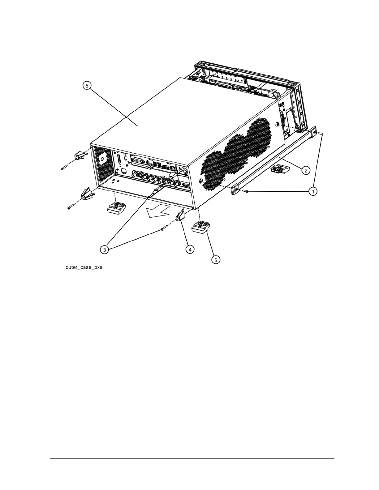
Figure 1 Instrument Outer Case Removal
Option EXM, External Mixing Upgrade Kit
Installation Note N9030-90058 9
Page 10
Option EXM, External Mixing Upgrade Kit
Top Brace Removal
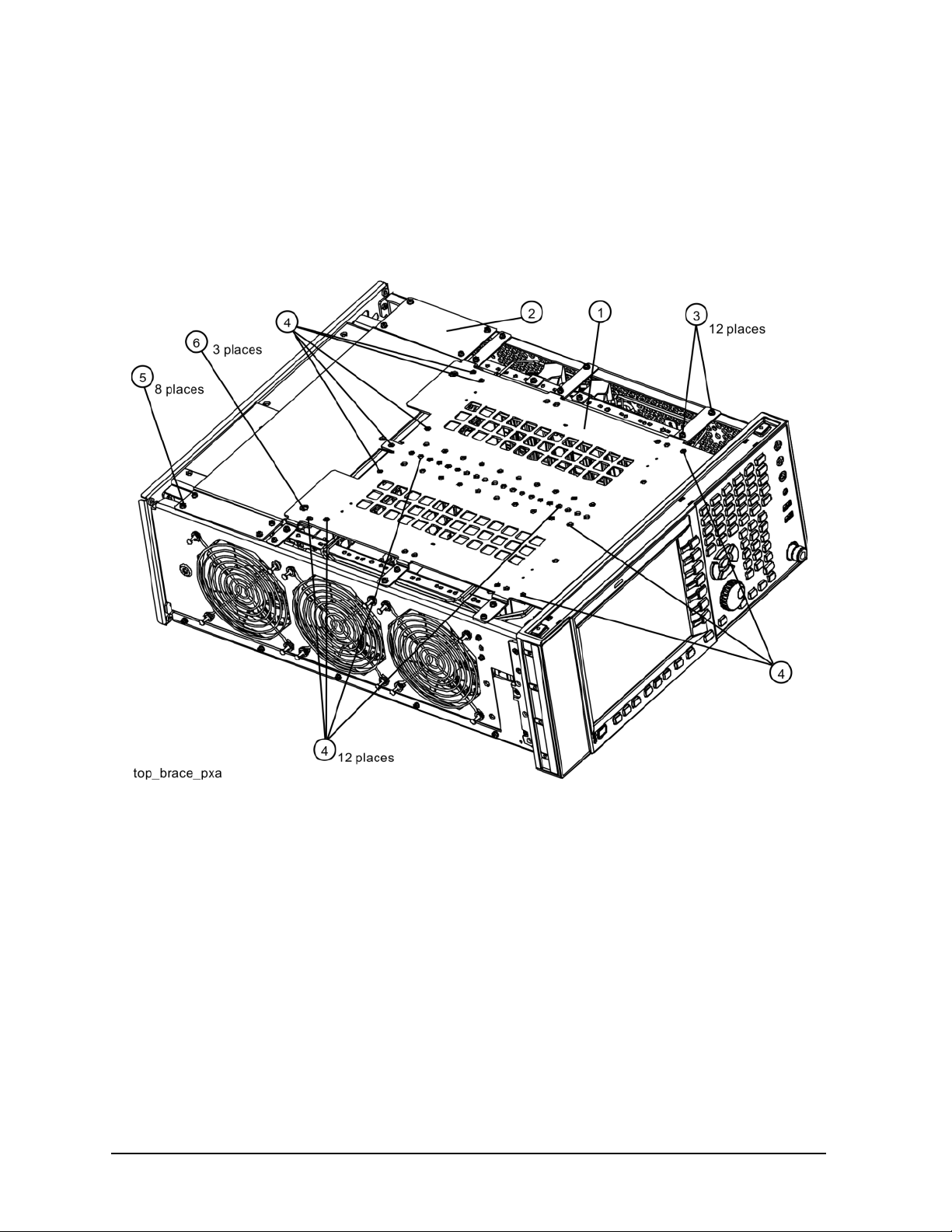
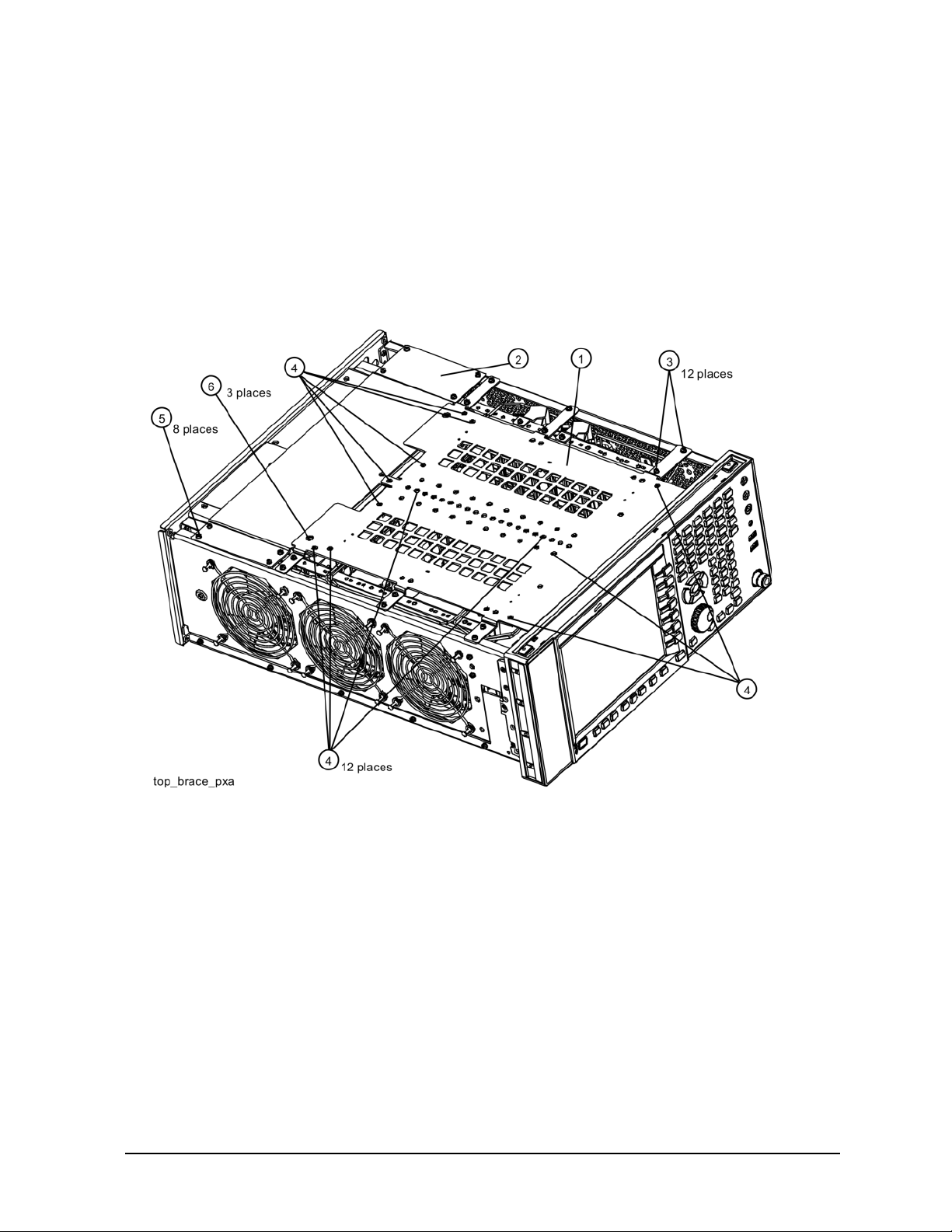
Refer to Figure 2. To remove the top brace (1), use the T-10 driver to remove the twelve screws (3)
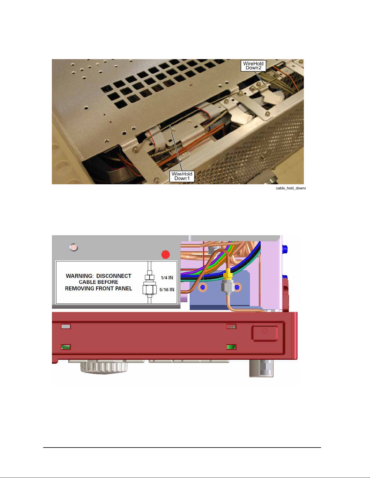
(0515-0372) attachi ng th e top bra ce to the chassis. Remove the wire hol d down 1 ( as sh own in Figure
3). Remove the twelve screws (14 screws with Option B1X) (4) (0515-1227) attaching the top brace
to the boards.
Figure 2 Top Brace Removal
10 Installation Note N9030-90058
Page 11
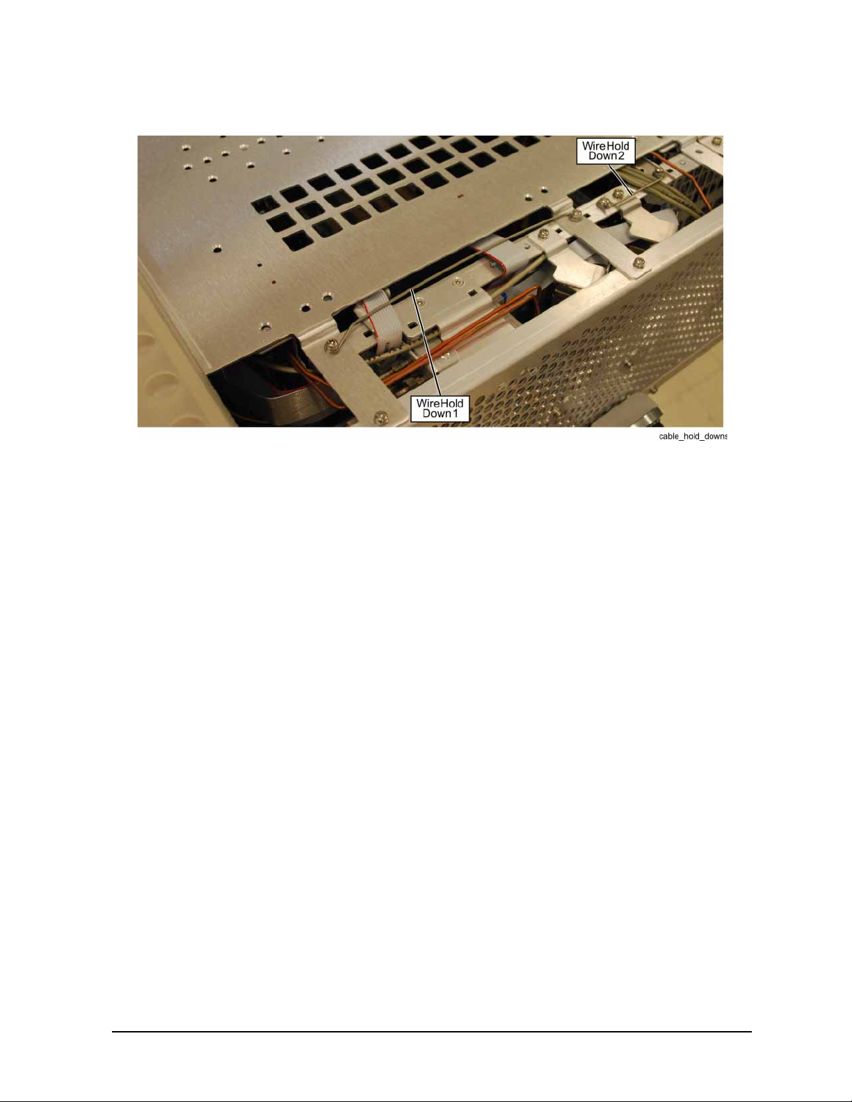
Figure 3 Wire Hold Downs
Option EXM, External Mixing Upgrade Kit
Installation Note N9030-90058 11
Page 12
Option EXM, External Mixing Upgrade Kit
Front Frame Assembly Removal
NOTE Make sure any connectors on the front panel are removed.
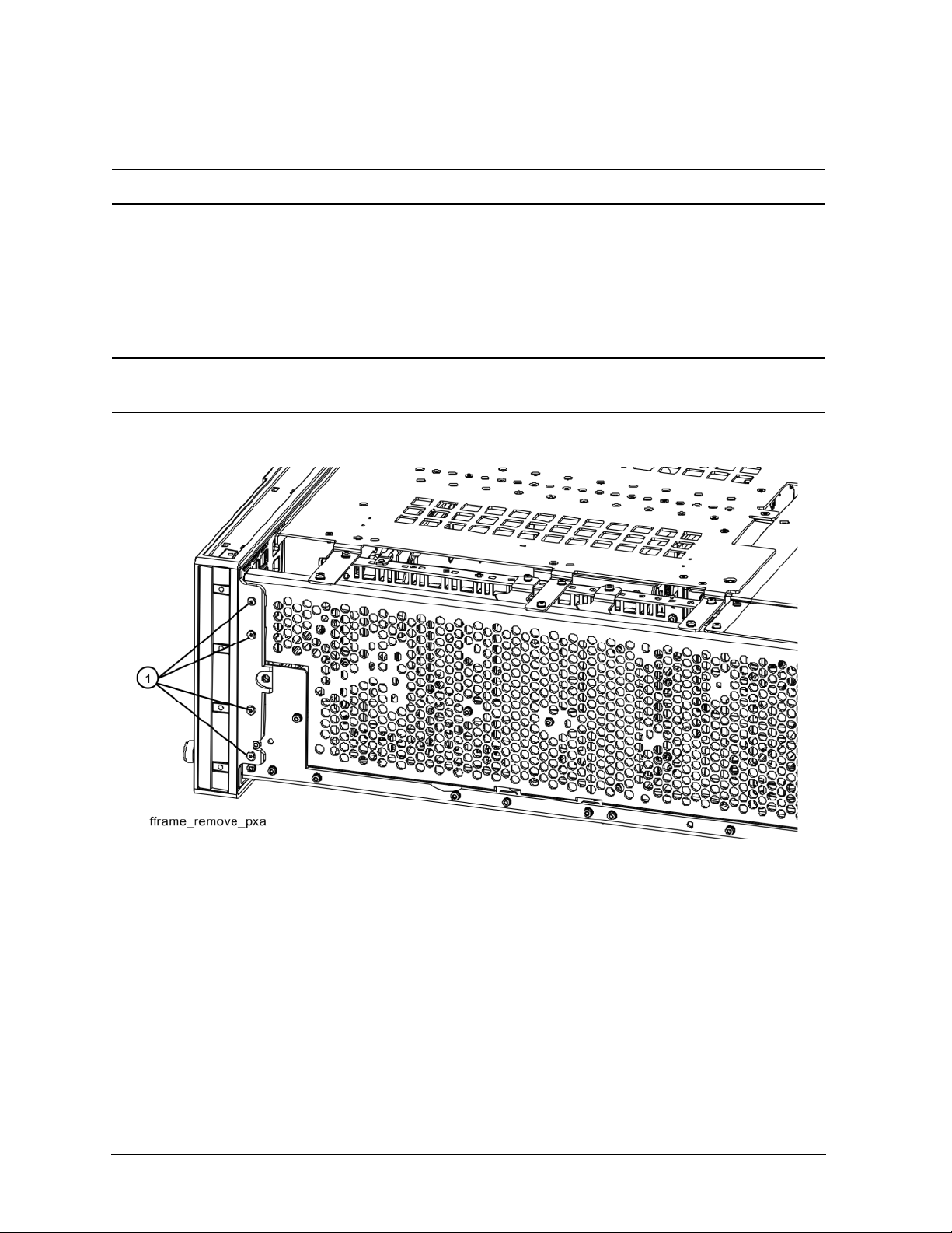
1. Refer to Figure 4. Using the T-10 driver, remove the eight screws (1) (0515-1035), four on each
side, to detach the Front Frame Assembly from the chassis.
2. Refer to Figure 5. Pull the Front Frame Assembly carefully away from the chassis. Remove the
ribbon cable W1 from the motherboard. The cable has locking tabs on each side, pinch and pul l to
release.
NOTE W1 may have locking springs on each side. Depress the spring on each side of the
connector to remove from the motherboard.
Figure 4 Front Frame Removal
12 Installation Note N9030-90058
Page 13
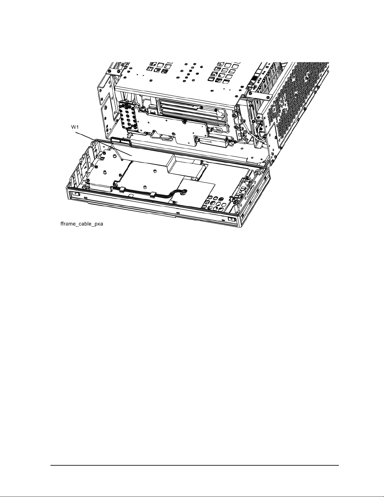
Figure 5 Front Panel Cable
Option EXM, External Mixing Upgrade Kit
Installation Note N9030-90058 13
Page 14
Option EXM, External Mixing Upgrade Kit
Add Cables to A13 Front End and A15 Front End Controller, RF/Microwave PXAs
NOTE This procedure only appl ies to RF and microwave PXAs (frequency range options
503, 508, 513, and 526). If your PXA has frequency range option 543, 544, or 550,
refer to the “Add Cables to A13 Front End and A15 Front End Controller,
Millimeter Wave PXAs” which follows.
1. Locate the longer of the two flexible coax assemblies in the Opt EXM Cable Kit with Markers.
This is cable W30 and should be labeled “8120-2027” and have the ends labeled “903” and “13”.
2. Connect the end of W30 that is labeled “903” to A15J903.
3. Connect the end of W30 that is labeled “13” to A13A1J13. J13 is one of the connectors along the
right side of A13, near the A12 BYFA. Torque the cable nut to 10 inch-pounds.
4. Remove the SMA termination on A13A1J8. A13A1J8 is directly above A13A1J13.
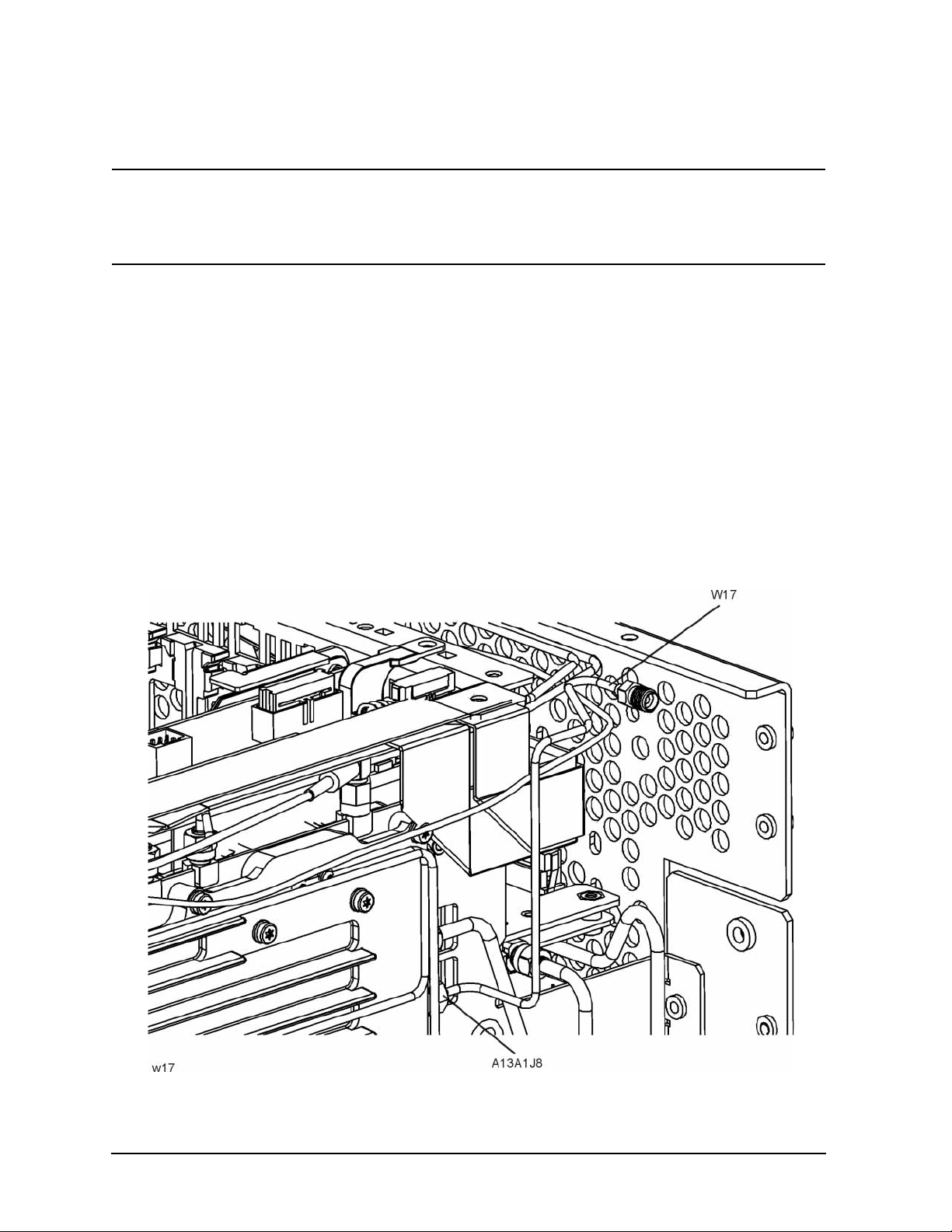
5. Locate semi-rigid coax cable, par t number N9020-20 132, in t he upgr ade ki t. This is W1 7. Connect
the end with the SMA male connect or A13A1J8, wi th the SMA femal e connecto r pointing to wards
where the front panel woul d be. The long, straight sec tion of W17 should be parallel to t he c ast i ng
of the A13 Front End and parallel to the side chassis. Refer to Figure 7.Torque the cable nut to 10
inch-pounds.
Figure 6 Orientation of W17 in an RF/Microwave PXA
14 Installation Note N9030-90058
Page 15
Option EXM, External Mixing Upgrade Kit
Add Cables to A13 Front End and A15 Front End Controller, Millimeter Wave
PXAs
NOTE This procedure only applies to millimeter wave PXAs (frequency range options
543, 544, and 550). If your PXA has frequency range opt ion 503, 508, 513, or 526,
refer to the “Add Cables to A13 Front End and A15 Front End Controller,
RF/Microwave PXAs” earlier in this note.
1. Locate the shorter of the two flexible coax assemblies in the Opt EXM Cable Kit with Markers.
This is cable W30 and should be labeled “8120-2025” and have the ends labeled “903” and “13”
2. Connect the end of W30 that is labeled “903” to A15J903.
3. Connect the end of W30 that is labeled “13” to A13A1J13. J13 is one of the connectors along the
top side of A13. Torque the cable nut to 10 inch-pounds.
4. Remove the SMA termination on A13A1J8. A13A1J8 is to the left of A13A1J13.
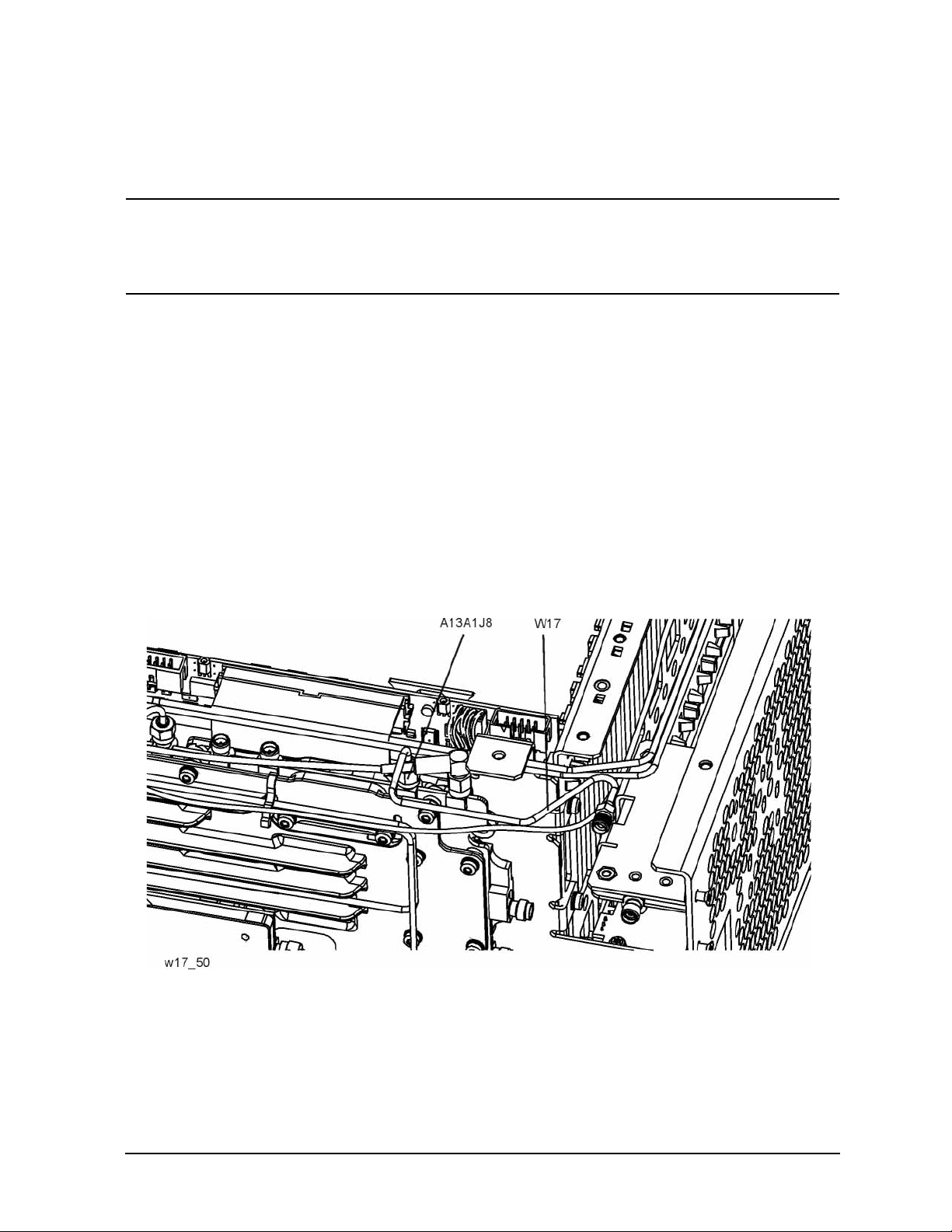
5. Locate semi-rigid coax cable, par t number N9020-20 167, in t he upgr ade ki t. This is W1 7. Connect
the end with the SMA male connect or A13A1J8, wi th the SMA femal e connecto r pointing to wards
where the front panel woul d be. The long, straight sec tion of W17 should be parallel to th e c ast i ng
of the A13 Front End and leve l. Refer to Fig ure 8. Not e that W29 is r outed b elow W17 . Torque the
cable nut to 10 inch-pounds.
Figure 7 Orientation of W17 in a Millimeter Wave PXA
Installation Note N9030-90058 15
Page 16
Option EXM, External Mixing Upgrade Kit
Add EXT MIXER Connector and Cable to Front Frame Assembly
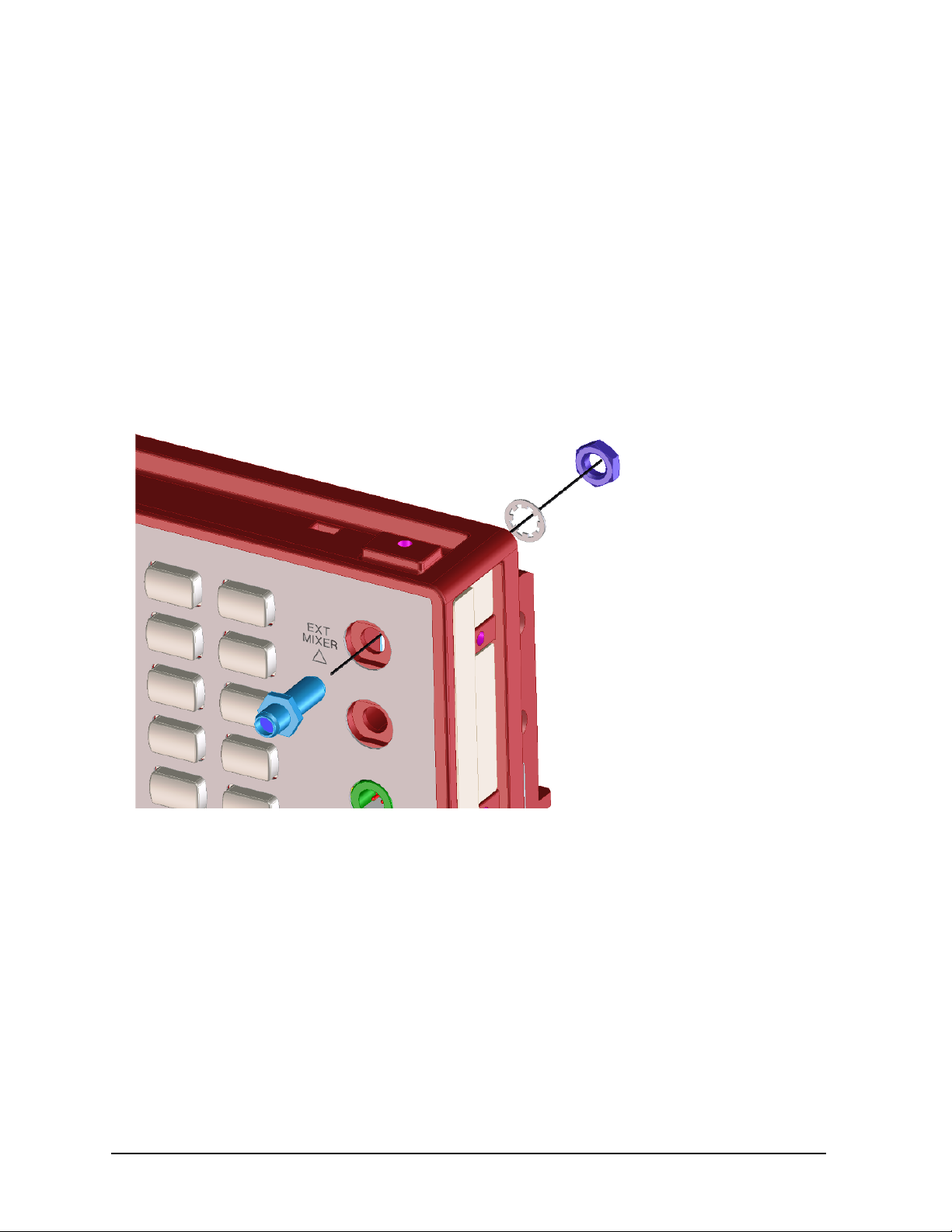
1. Locate the SMA fem ale to SMA fem ale connector (1250-1666), ¼” lockwasher (2190-0067), and
¼” hex nut (2950-0223) in the kit. If the SMA con nec tor i ncl udes hardware, discard t hat h ard ware
and use the 2190-0067 lockwasher and 2950-0223 hex nut included in this kit.
2. Remove the hole-plug in the top-most hole in the upper right corner of the front frame assembly.
On newer PXAs, this hole will be la beled “EXT MIXER”. On older PXAs, there wil l be no label; a
label is included in this kit and will be added later.
3. Insert the SMA female to SMA female connector in the hole in the front frame assembly from the
front of the assembly. The hex feature on the connector should engage with the recess in the front
frame assembly. Refer to Figure 8. Secure the connector using the ¼” lockwasher and ¼” hex nut
from the rear. Torque to 21 inch-pounds.
Figure 8 Attaching SMA Female Connector
4. Locate the External Mixing, Front Panel semi-rigid coax assembly in the kit, part number
N9020-20166. This is W29. Note that this cable is symmetrical; either end can be connected to the
front-panel connector.
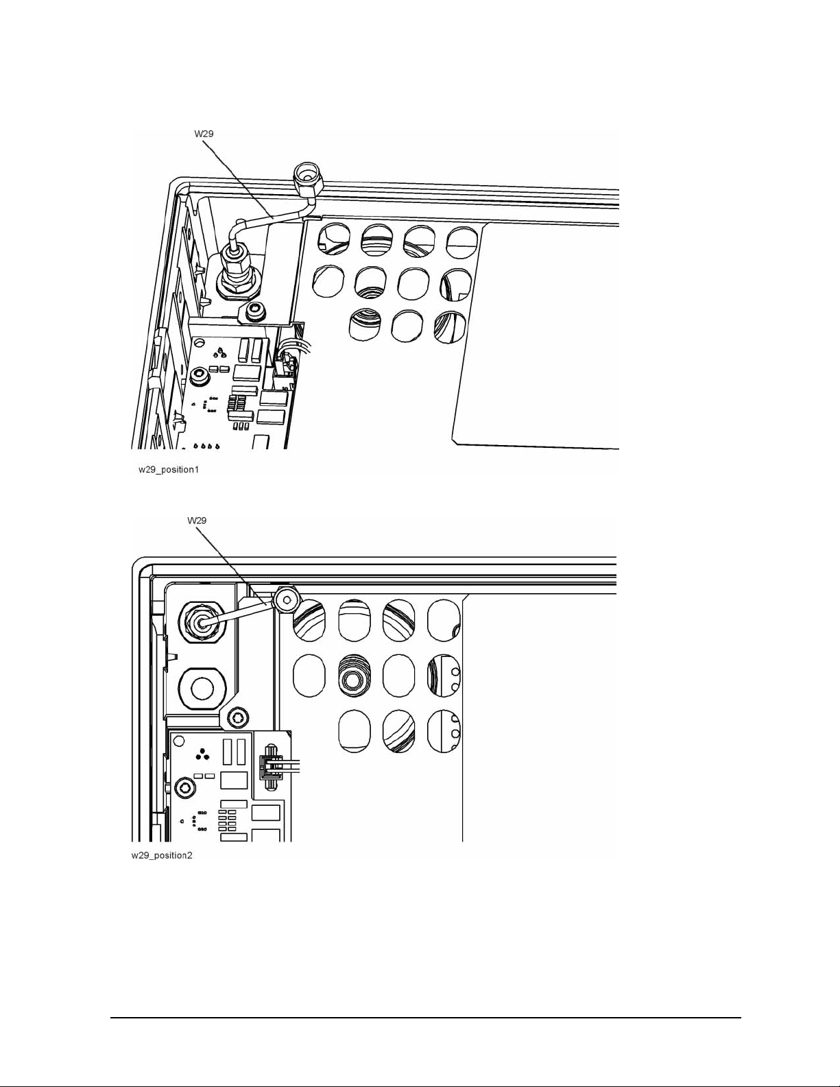
5. Connect one end of W29 to the SMA female connector as shown in Figure 10.
6. Orient W29 so that the cable slopes upward from the Ext Mixer connector at a 15 degree angle.
The top of the connector should be approximately level with the top of the shield over the Front
Panel Interface board. Refer to Figure 11. Torque the cable nut on the Ext Mixer connector to 10
inch-pounds.
16 Installation Note N9030-90058
Page 17
Option EXM, External Mixing Upgrade Kit
Figure 9 Connecting W29 to Ext Mixer Connector
Figure 10 Proper Orientation of W29
7. If the new front panel SMA connector is not already labeled “EXT MIXER”, locate the External
Mixing Label in the kit.
8. Clean the area around the SMA connector to ensure the new label will adhere well.
9. Peel off the ba cking from t he label and caref ully appl y the labe l to the f ront pane l, making sur e that
the straight edges of the label are parallel to the top and side edges of the front frame.
Installation Note N9030-90058 17
Page 18
Option EXM, External Mixing Upgrade Kit
Front Frame Replacement
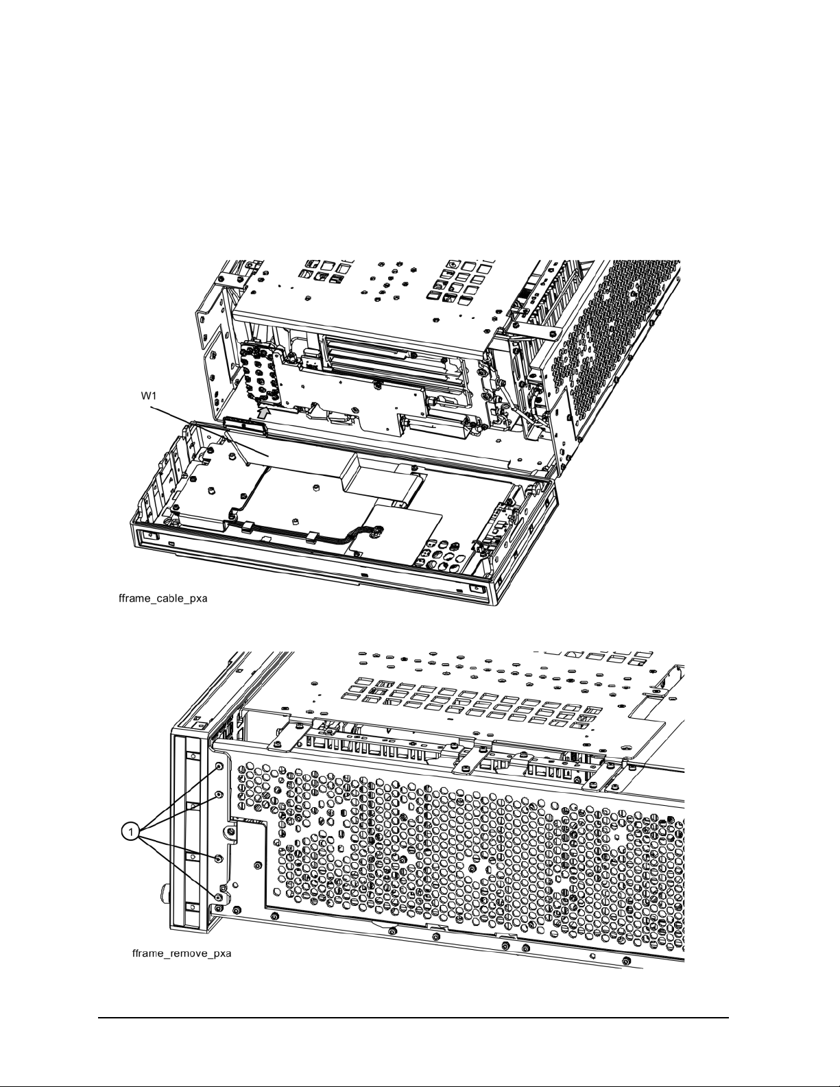
1. Refer to Figure 11. Reattach the ribbon cable W1. Ensure the locking tabs are engaged.
2. Refer to Figure 12. Carefully position the Front Frame Assembly onto the chassis. Ensure no
cables are crushed. Replace the eight screws (1) (0515-1035), four on each side of the chassis.
Torque to 9 inch pounds.
Figure 11 Front Panel Cable
Figure 12 Front Frame Replacement
18 Installation Note N9030-90058
Page 19
Option EXM, External Mixing Upgrade Kit
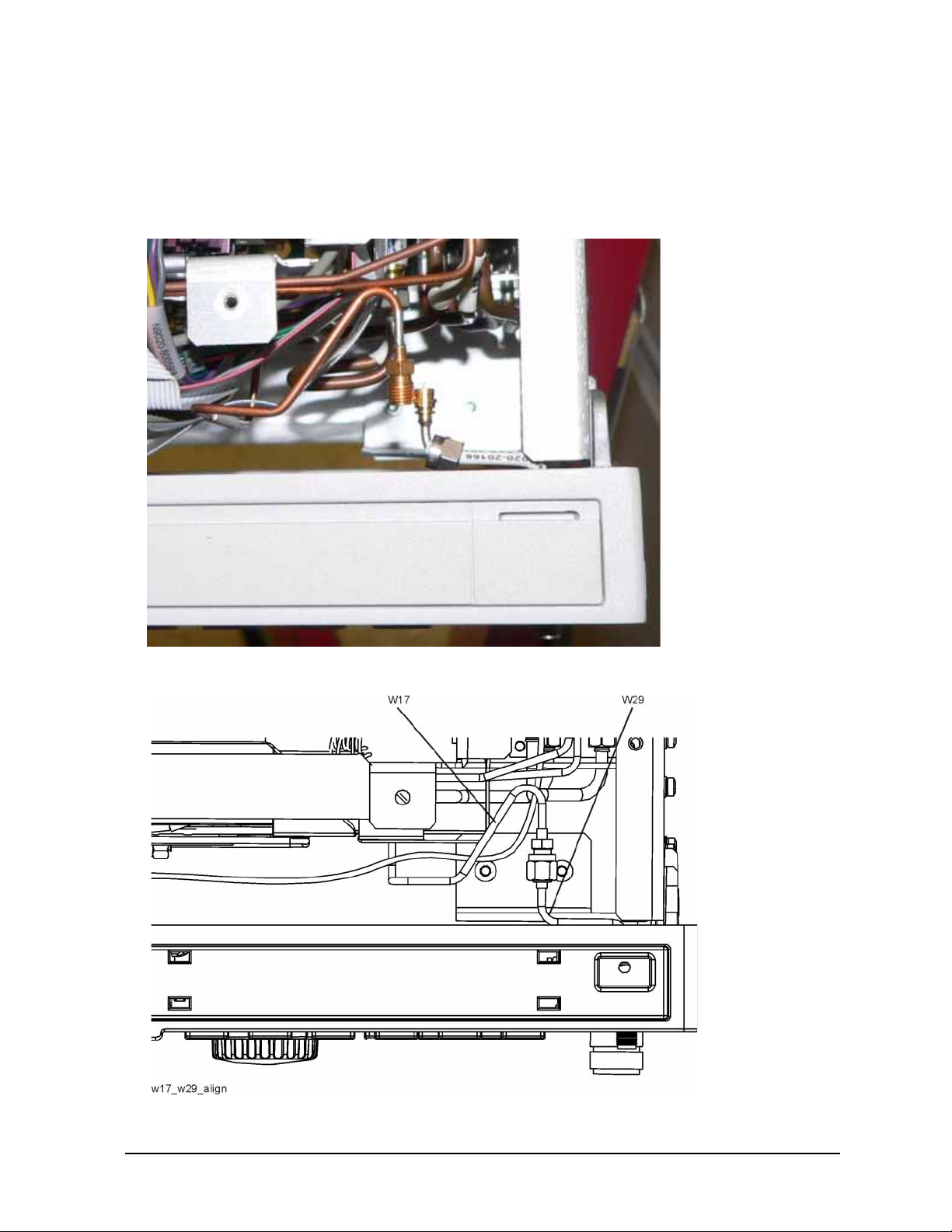
3. Refer to Figure 13. When the front panel is installed, cables W17 and W29 typically do not align.
This is OK since the cab les are flexible.
4. Refer to Figure 14. Align and connect cables W17 and W29. Hand-tighten the nut.
Figure 13 W17 and W29 Before Alignment
Figure 14 W17 and W29 Properly Aligned
Installation Note N9030-90058 19
Page 20
Option EXM, External Mixing Upgrade Kit
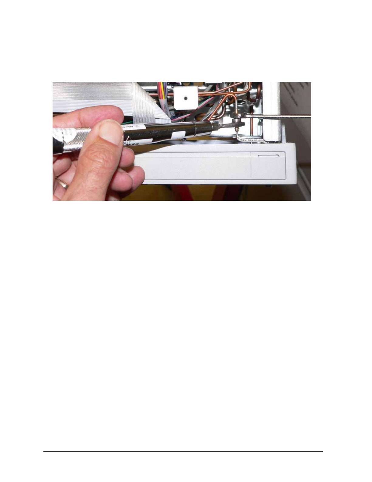
5. Refer to Figure 15 . Use a ¼” open-en d wrench to pre vent the SMA fe male connect or on W17 from
twisting. Use a 5/16” torque wrench to torque the nut on W29 to 10 inch-pounds.
Figure 15 Torque Cable W29 onto W17
20 Installation Note N9030-90058
Page 21
Option EXM, External Mixing Upgrade Kit
Top Brace Replacement
1. Refer to Figure 16. To replace the top brace, place t he brace in the cor rect posi tion and at tach to t he
chassis using the twelve screws (3) (0515-0372). Attach the top brace to the boards using the
twelve screws (14 screws with Option B1X) (4) (0515-1227).
2. Refer to Figure 17. Reinstall wire hold down 1.
3. Torque all screws to 9 inch-pounds.
Figure 16 Top Brace Replacement
Installation Note N9030-90058 21
Page 22
Option EXM, External Mixing Upgrade Kit
Figure 17 Wire Hold Downs
4. In the upgrade kit, locate the Warning Label, N9030-80018.
5. Refer to Figure 18. Attach the Warning Label to the top brace as shown.
Figure 18 Add Warning Label to Top Brace
22 Installation Note N9030-90058
Page 23
Option EXM, External Mixing Upgrade Kit
Final Assembly
1. Refer to Figure 19. Slide the instrument cover back onto the deck from the rear. The seam on the
cover should be on the bottom. Be sure the cover seats into the gasket groove in the Front Frame
Assembly.
2. Replace the four rear feet t o the rea r of the i nstru ment. Torque the rear feet screws ( 0515-161 9 and
3050-0893 washers) to 21 inch pounds.
3. Replace the bottom fee t b y sl iding into place until they snap in. Install the lo cks by pressing in flat.
4. Replace the handle straps on both sides of the instrument. Torque the handle strap screws to 21
inch pounds.
5. Locate the 50 ohm SMA termination in the kit, part number 1810-0118. Attach the SMA
termination to the front panel EXT MIXER connector.
Figure 19 Instrument Outer Cover Replacement
Installation Note N9030-90058 23
Page 24
Option EXM, External Mixing Upgrade Kit
Update Instrument Software
Option EXM requires instru ment sof tware A.10.00 or lat er. This will assure the latest a djust ments a nd
performance verification tests will run. The currently-installed software was noted in the Analyzer
Information procedure at the beginning of the installation procedure.
The latest revision of the instrument software may be downloaded from:
http://www.agilent.com/find/xseries_software
Licensing the New Option
Installation Procedure over USB
1. Locate the Option Upgrade Entitlement Certificate (5964-5178) from the kit.
2. Redeem the Option Upgrade Entitlement Certificate by following the instructions on the
Certificate.
3. After redeeming your Option Upgrade Entitlement Certificate you will receive an email with an
attached License File.
4. Locate a USB storage device. Perform a virus scan on this device before use.
5. Save the License File to the root directory of the USB Storage Device.
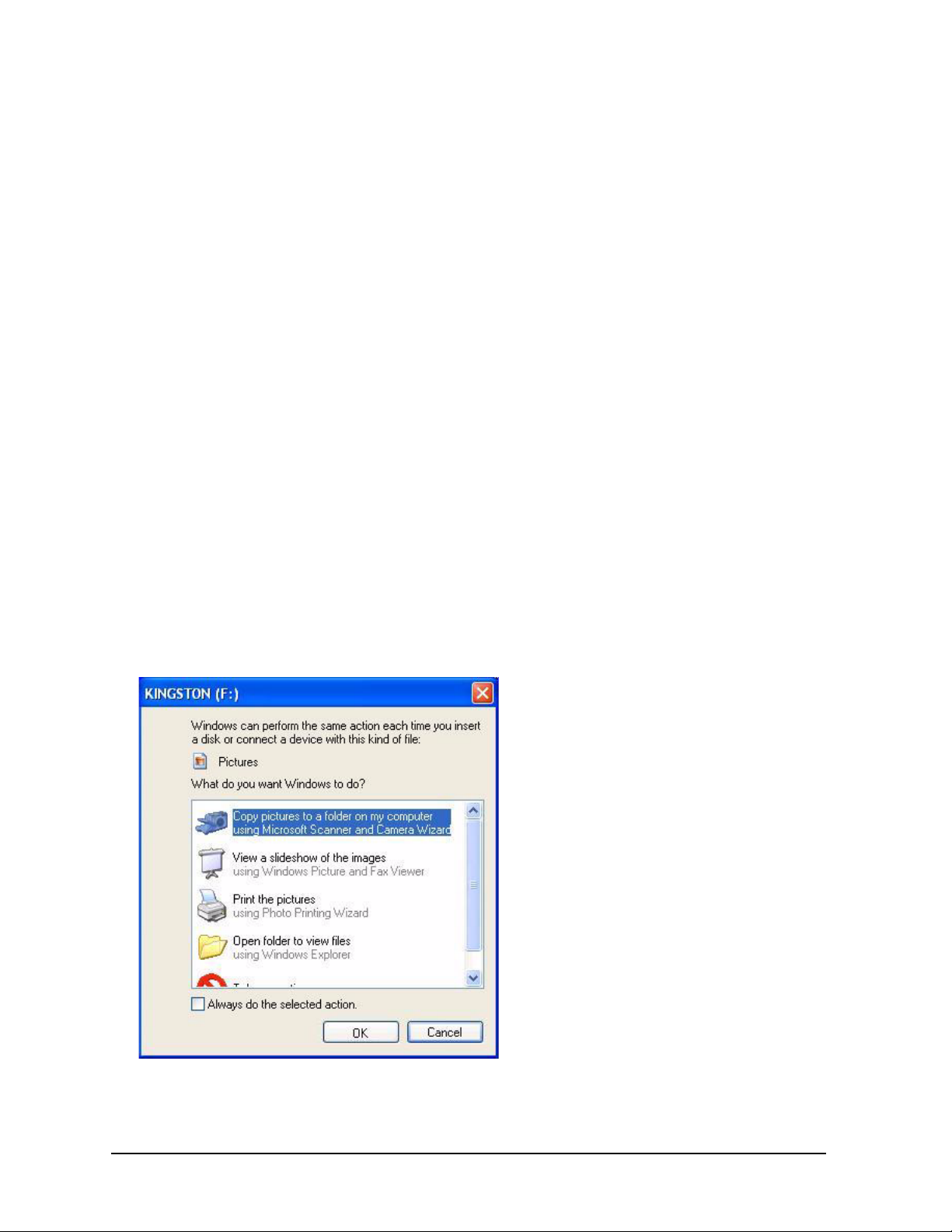
6. Connect the USB Storage Device to one of the analyzer’s USB ports. Connect a mouse to another
USB port. Windows will detect the new hardware and may display the configuration menu shown
in Figure 20. This menu may be configured according to your preferences.
Figure 20 USB Storage Device Configuration Menu
7. The analyzer will automatica lly consume th e License Fil e (this may tak e a few minutes) . When the
24 Installation Note N9030-90058
Page 25
Option EXM, External Mixing Upgrade Kit
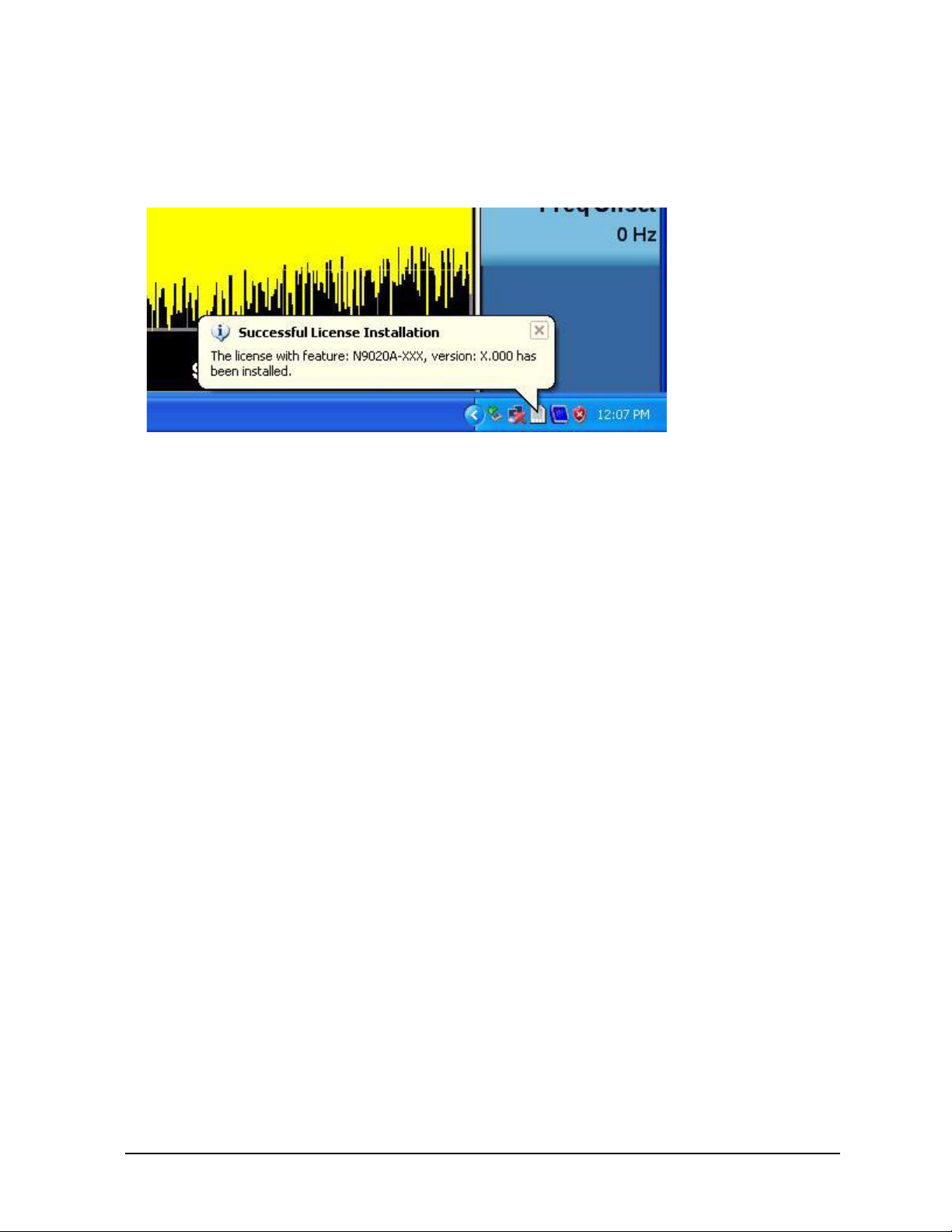
License File is consumed the Agilent License Manager will display a “Successful License
Installation” message as shown in Figure 21.
Figure 21 Successful License Installation
Alternate Installation Procedure
The License File can be manually installed over USB or LAN by placing the license file in the
following analyzer folder: C:\Program Files\Agilent\licensing.
Verify the License Installation
1. Before the licenses wil l be rec ognized, the XSA application must be res ta rt ed. Pr es s File, Exit. An
Exit Analyzer dialog box will appear; press
2. Double-click on the LaunchXSA icon on the Windows desktop. Wait for the XSA application to
finish starting (the analyzer should be sweeping).
3. Press
System, Show, System on the analyzer to displ ay a list of all displayed opt ions. You should
see the following option listed:
• N9030A-EXM External Mixing
Enter to confirm the exit.
Verify Optional Functionality
1. Press Mode, Spectrum Analyzer
2. Press Input/Output
3. Verify that softkey “External Mixer” appears below the “RF Input” softkey
Installation Note N9030-90058 25
Page 26

Option EXM, External Mixing Upgrade Kit
Utilities, Adjustments, and Performance Verification Tests
Calibration Software and specified test equipment is required to perform the adjustments, and can be
used to automate the performance verification testing . Inf orma ti on on how t o obt ain this software can
be found at:
http://www.agilent.com/find/calibrationsoftware
Utilities Required
None
Adjustments Required
The following adjustment s are th e minimum set required t o ensure t hat the newly inst alled ha rdware is
functioning properly
• IF Input Gain Adjustment
• LO Output Power Adjustment
Performance Testing Required
The following performance verification tests are the minimum set required to ensure that this newly
installed option is functioning properly.
• IF Input Gain Accuracy
• LO Output Power Accuracy
A full calibration is required to assure the instrument meets all spec ifications
The end user must ultimately determine whet her they want a full calibration to be per for med af ter the
installation of this upgrade or not. If a full calibration is required, arrangements regarding the level of
calibration must be made between the end user and the calibration provider.
For assistance, contact you r nea rest Agi lent Technologies Sales and Serv ice Of fi ce. To find your local
Agilent office access the following URL, or if in the United States, call the following telephone
number:
http://www.agilent.com/find/assist
1-800-829-4444 (8 am - 8 pm ET, Monday - Friday)
26 Installation Note N9030-90058
 Loading...