

Page 1

Test Equipment Depot - 800.517.8431 - 99 Washington Street Melrose, MA 02176 - TestEquipmentDepot.com
Keysight N8262A P-Series
Modular Power Meter
Installation
Guide
Page 2

Notices
CAUTION
WARNING
Copyright Notice
© Keysight Technologies 2007 - 2017
No part of this manual may be repro-
duced in any form or by any means
(including electronic storage and
retrieval or translation into a foreign
language) without prior agreement and
written consent from Keysight Technologies as governed by United States and
international copyright laws.
Manual Part Number
N8262-90005
Edition
Edition 5, August 4, 2017
Printed in:
Printed in Malaysia
Published by:
Keysight Technologies
Bayan Lepas Free Industrial Zone,
11900 Penang, Malaysia
Technology Licenses
The hardware and/or software
described in this document are furnished under a license and may be
used or copied only in accordance with
the terms of such license.
Declaration of Conformity
Declarations of Conformity for this
product and for other Keysight products may be downloaded from the
Web.
U.S. Government Rights
The Software is “commercial computer
software,” as defined by Federal Acquisition Regulation (“FAR”) 2.101. Pursuant to FAR 12.212 and 27.405-3 and
Department of Defense FAR Supplement (“DFARS”) 227.7202, the U.S.
government acquires commercial computer software under the same terms
by which the software is customarily
provided to the public. Accordingly,
Keysight provides the Software to U.S.
government customers under its standard commercial license, which is
embodied in its End User License
Agreement (EULA). The license set
forth in the EULA represents the
exclusive authority by which the U.S.
government may use, modify,
distribute, or disclose the Soft-ware.
The EULA and the license set forth
therein, does not require or per-mit,
among other things, that Keysight: (1)
Furnish technical information related to
commercial computer
commercial computer software
documentation that is not customarily
provided to the public; or (2) Relinquish
to,
or otherwise provide, the government rights in excess of these rights
customarily provided to the public to
use, modify, reproduce, release, per-form,
display, or
computer software
com-puter software documentation.
No additional government
requirements beyond those set forth in
the EULA shall apply, except to the
extent
licenses are explicitly required from all
providers of commercial computer
software pursu-ant to the FAR and the
DFARS and are set forth specifically in
writing
Keysight shall be under no obligation to
update, revise or otherwise modify the
Software. With respect to any
technical data as defined by FAR
2.101, pursuant to FAR 12.211 and
27.404.2 and DFARS 227.7102, the
U.S. government acquires no greater
than Limited Rights as defined in FAR
27.401 or DFAR 227.7103-5 (c), as
applicable in any technical data.
disclose commercial
that those terms, rights, or
else-where in the EULA.
soft-ware or
or commercial
Warranty
THE MATERIAL CONTAINED IN THIS
DOCUMENT IS PROVIDED “AS IS,”
AND IS SUBJECT TO BEING
CHANGED, WITHOUT NOTICE, IN
FUTURE EDITIONS. FURTHER, TO THE
MAXIMUM EXTENT PERMITTED BY
APPLICABLE LAW, KEYSIGHT DISCLAIMS ALL WARRANTIES, EITHER
EXPRESS OR IMPLIED, WITH REGARD
TO THIS MANUAL AND ANY INFORMATION CONTAINED HEREIN, INCLUDING BUT NOT LIMITED TO THE
IMPLIED WARRANTIES OF MERCHANTABILITY AND FITNESS FOR A
PARTICULAR PURPOSE. KEYSIGHT
SHALL NOT BE LIABLE FOR ERRORS
OR FOR INCIDENTAL OR CONSEQUENTIAL DAMAGES IN CONNECTION
WITH THE FURNISHING, USE, OR
PERFORMANCE OF THIS DOCUMENT
OR OF ANY INFORMATION CONTAINED HEREIN. SHOULD KEYSIGHT
AND THE USER HAVE A SEPARATE
WRITTEN AGREEMENT WITH WARRANTY TERMS COVERING THE MATERIAL IN THIS DOCUMENT THAT
CONFLICT WITH THESE TERMS, THE
WARRANTY TERMS IN THE SEPARATE
AGREEMENT SHALL CONTROL.
Safety Information
A CAUTION notice denotes a hazard. It
calls attention to an operating procedure, practice, or the like that, if not
correctly performed or adhered to,
could result in damage to the product
or loss of important data. Do not proceed beyond a CAUTION notice until
the indicated conditions are fully
understood and met.
A WARNING notice denotes a hazard. It
calls attention to an operating procedure, practice, or the like that, if not
correctly performed or adhered to,
could result in personal injury or death.
Do not proceed beyond a WARNING
notice until the indicated conditions are
fully understood and met.
2 Keysight N8262A Installation Guide
Page 3

Certification
Keysight Technologies certifies that this product met its published specifications
at the time of shipment. Keysight further certifies that its calibration
measurements are traceable to the United States National Institute of Standard
and Technology (formerly National Bureau of Standards), to the extent allowed by
that organization’s calibration facility, and to the calibration facilities of other
International Standards Organization members.
General Warranty
The material contained in this document is provided “as is,” and is subject to
being changed, without notice, in future editions. Further, to the maximum extent
permitted by applicable law, Keysight disclaims all warranties, either express or
implied with regard to this manual and any information contained herein,
including but not limited to the implied warranties of merchantability and fitness
for a particular purpose. Keysight shall not be liable for errors or for incidental or
consequential damages in connection with the furnishing, use, or performance of
this document or any information contained herein. Should Keysight and the user
have a separate written agreement with warranty terms covering the material in
this document that conflict with these terms, the warranty terms in the separate
agreement shall control. Duration and conditions of warranty for this product may
be superseded when the product is integrated into (becomes a part of) other
Keysight products. During the warranty period, Keysight will, at its option, either
repair or replace products which prove to be defective. The warranty period begins
on the date of delivery or on the date of installation if installed by Keysight.
Warranty Service
For warranty service or repair, this product must be returned to a service facility
designated by Keysight. For products returned to Keysight for warranty service,
the Buyer shall prepay shipping charges to Keysight and Keysight shall pay
shipping charges to return the product to the Buyer. However, the Buyer shall pay
all shipping charges, duties, and taxes for products returned to Keysight from
another country.
Keysight N8262A Installation Guide 3
Page 4

Limitation of Warranty
The foregoing warranty shall not apply to defects resulting from improper or
inadequate maintenance by the Buyer, Buyer-supplied products or interfacing,
unauthorized modification or misuse, operation outside of the environmental
specifications for the product, or improper site preparation or maintenance.
The design and implementation of any circuit on this product is the sole
responsibility of the Buyer. Keysight does not warrant the Buyer’s circuitry or
malfunctions of Keysight products that result from the Buyer’s circuitry. In
addition, Keysight does not warrant any damage that occurs as a result of the
Buyer’s circuit or any defects that result from Buyer-supplied products.
To the extent allowed by local law, Keysight makes no other warranty, expressed
or implied, whether written or oral with respect to this product and specifically
disclaims any implied warranty or condition of merchantability, fitness for a
particular purpose or satisfactory quality.
Exclusive Remedies
To the extent allowed by local law, the remedies provided herein are the Buyer’s
sole and exclusive remedies. Keysight shall not be liable for any direct, indirect,
special, incidental, or consequential damages (including lost profit or data),
whether based on warranty, contract, tort, or any other legal theory.
4 Keysight N8262A Installation Guide
Page 5

Restricted Rights Legend
The Software and Documentation have been developed entirely at private
expense. They are delivered and licensed as “commercial computer software” as
defined in DFARS 252.227-7013 (Oct 1988), DFARS 252.211-7015 (May 1991), or
DFARS 252.227-7014 (Jun 1995), as a “commercial item” as defined in
FAR 2.101(a), or as “restricted computer software” as defined in FAR 52.227-19
(Jun 1987) (or any equivalent agency regulation or contract clause), whichever is
applicable. You have only those rights provided for such Software and
Documentation by the applicable FAR or DFARS clause or the Keysight standard
software agreement for the product involved.
Technology Licenses
The hardware and/or software described in this document are furnished under a
license and may be used or copied only in accordance with the terms of such
license.
Keysight N8262A Installation Guide 5
Page 6
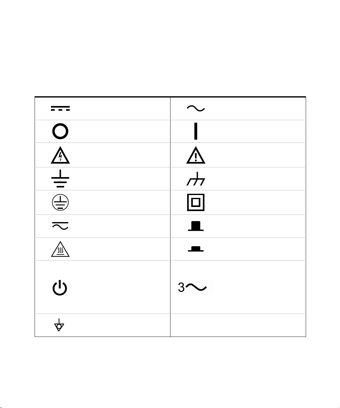
Safety Symbols
The following symbols on the instrument and in the documentation indicate
precautions which must be taken to maintain safe operation of the instrument.
Direct current (DC). Alternating current (AC).
Off (mains supply). On (mains supply).
Caution, risk of electric shock.
Earth (ground) terminal. Frame or chassis (ground) terminal.
Protective earth (ground) terminal.
Caution, risk of danger (refer to this
manual for specific Warning or Caution
information).
Equipment protected throughout by
double insulation or reinforced
insulation.
Both direct and alternating current.
Caution, hot surface. In position of a bi-stable push control.
This symbol indicates the operating
switch for ‘Stand-by’ mode. Note, the
instrument is NOT isolated from the
mains when the switch is pressed.
To isolate the instrument, the mains
coupler (mains input cord) should be
removed from the power supply.
Equipotentiality.
Out position of a bi-stable push
control.
Three-phase alternating current.
6 Keysight N8262A Installation Guide
Page 7

Safety Considerations
Read the information below before using this instrument.
The following general safety precautions must be observed during all phases of
operation, service, and repair of this instrument. Failure to comply with these
precautions or with specific warnings elsewhere in this manual violates safety
standards for design, manufacture, and intended use of the instrument. Keysight
Technologies assumes no liability for the customer’s failure to comply with these
requirements.
General Safety Information
This is a Safety Class I instrument (provided with a protective earthing ground,
incorporated in the power cord). The mains plug shall only be inserted in a socket
outlet provided with a protective earth contact. Any interruption of the protective
conductor inside or outside of the instrument is likely to make the instrument
dangerous. Intentional interruption is prohibited.
Keysight N8262A Installation Guide 7
Page 8

WARNING
– DO NOT operate the product in an explosive atmosphere or in the
CAUTION
presence of flammable gases or fumes.
– DO NOT use repaired fuses or short-circuited fuseholders: For continued
protection against fire, replace the line fuse(s) only with fuse(s) of the
same voltage and current rating and type.
– DO NOT perform procedures involving cover or shield removal unless you
are qualified to do so: Operating personnel must not remove equipment
covers or shields. Procedures involving the removal of covers and shields
are for use by service-trained personnel only.
– DO NOT service or adjust alone: Under certain conditions, dangerous
voltages may exist even with the equipment switched off. To avoid
dangerous electrical shock, service personnel must not attempt internal
service or adjustment unless another person, capable of rendering first
aid and resuscitation, is present.
– DO NOT operate damaged equipment: Whenever it is possible that the
safety protection features built into this product have been impaired,
either through physical damage, excessive moisture, or any other reason,
REMOVE POWER and do not use the product until safe operation can be
verified by service-trained personnel. If necessary, return the product to a
Keysight Technologies Sales and Service Office for service and repair to
ensure the safety features are maintained.
– DO NOT substitute parts or modify equipment: Because of the danger of
introducing add itional hazards, do not install substitute parts or perform
any unauthorized modification to the product. Return the product to a
Keysight Technologies Sales and Service Office for service and repair to
ensure the safety features are maintained.
– Applying excessive voltage or overloading the device will cause
irreversible damage to the circuitry.
– Use the device with the cables provided.
8 Keysight N8262A Installation Guide
Page 9

General Specifications
Environmental conditions
The N8262A is designed for indoor use and in an area with low condensation. The
table below shows the general environmental requirements for this instrument.
Environmental condition Requirement
Temperature
Humidity Up to 95% relative humidity RH to +40°C
Altitude 3000 m (9,840 ft.)
Pollution degree 2
EMC Meets EN55011: 1991 (Group 1, Class A)
Physical specifications
Operating condition
– 0 °C to 55 °C
Storage condition
– –20 °C to 70 °C
Net weight ≤ 3.5 kg (7.7 lb) approximately
Shipping weight ≤ 7.7 kg (17.0 lb) approximately
Dimensions
44.2 mm H x 212.6 mm W x 420.3 mm D
(1.75 in x 8.5 in x 19.63 in)
Keysight N8262A Installation Guide 9
Page 10
Power requirements
WARNING
CAUTION
Line power
Cooling Requirements
To provide adequate cooling, and air gap of approximately 75mm (3ins) should be
maintained around the vented sections of the instrument.
Use
This instrument is designed for indoor use only.
– Appliance coupler (mains input power cord) is the power disconnect
device. Do not position the instrument such that access to the coupler is
impaired.
– For continue protection against fire hazard, replace the l ine fuse only with
the same type and line rating (250V, F3.15A, 20mm fast blow fuse with
high breaking capacity, Keysight Part Number 2110-0957).
The use of other fuses or materials is prohibited.
Input voltage range
Input frequency range
Power requirement
100 – 120 V ±10%
220 – 240 V ± 10%
50 – 60 Hz ±10% (all voltages)
400 – 440 Hz (100 – 120 V only)
50 VA (30 Watts)
(not exceeding 75 VA (50 Watts))
– No operator serviceable parts inside. Refer servicing to qualified
personnel. To prevent electrical shock do not remove covers
– If this instrument is not used as specified, the protection provided by the
equipment could be impaired. This instrument must be used in a normal
condition only (in which all means for protection are intact).
This instrument is designed for use in Installation Category II and Pollution
Degree 2 per IEC61010 and 60664 respectively.
10 Keysight N8262A Installation Guide
Page 11

Compliance and Markings
Electromagnetic Compatibility (EMC)
This product complies with the essential requirements of the following applicable
European Directives, and carries the CE marking accordingly:
– Low Voltage Directive (73/23/EEC, amended by 93/68/EEC)
– EMC Directive (89/336/EEC, amended by 93/68/EEC)
This product conforms with the following product standards:
EMC Standard Limit
Safety
IEC 61326-1:1997+A1:1998/EN 61326-1:1997+A1:1998CISPR
11:1990/EN 55011:1991
The conformity assessment requirements have been met using the technical
construction file route to compliance, using EMC test specifications EN
55011:1991 (Group 1, Class A). In order to preserve the EMC performance of the
product, any cable which becomes worn or damaged must be replaced with the
same type and specification.
The product also meets the following EMC standards:
– Australia/New Zealand: AS/NZS 2064.1
– Canada: ICES-001:1998
This product conforms to the requirements of the following safety standards:
– EN61010-1: 2001 / IEC 61010-1:2001
– Canada: CSA C22.2 No. 61010-1:2004
– USA: UL: 61010-1:2004
Class A, Group 1
Keysight N8262A Installation Guide 11
Page 12
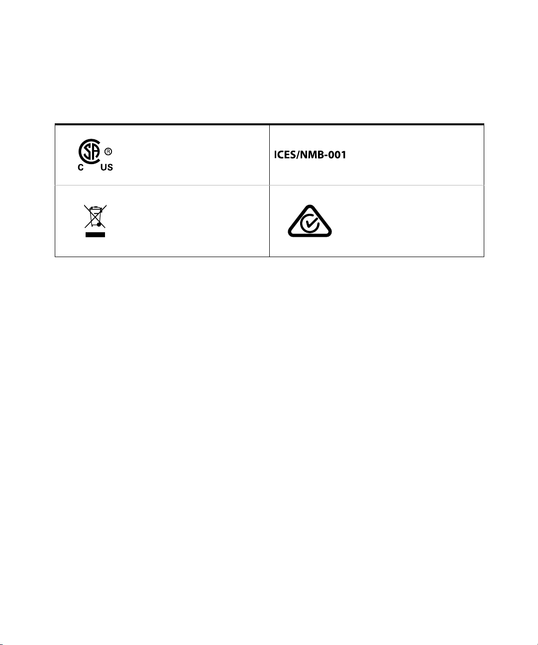
Regulatory Markings
The CSA mark is a registered
trademark of the Canadian
Standards Association.
This instrument complies with the
WEEE Directive (2002/96/EC) marking
requirement. This affixed product label
indicates that you must not discard
this electrical or electronic product in
domestic household waste.
ICES/NMB-001 indicates that this ISM
device complies with the
Canadian ICES-001.
Cet appareil ISM est conforme a la
norme NMB-001 du Canada.
The RCM mark is a registered
trademark of the Australian
Communications and Media Authority.
12 Keysight N8262A Installation Guide
Page 13

Regulatory Information
Sound Emission
Herstellerbescheinigung
Diese Information steht im Zusammenhang mit den Anforderungen der
Maschinenlarminformationsverordnung vom 18 Januar 1991.
Sound Pressure LpA < 70 dB.
Am Arbeitsplatz.
Normaler Betrieb.
Nach DIN 45635 T. 19 (Typprufung).
Manufacturers Declaration
This statement is provided to comply with the requirements of the German Sound
DIN 45635 T. 19 (Typprufung).
Sound Pressure LpA < 70 dB.
At operator position.
Normal operation.
According to ISO 7779 (Type Test).
Keysight N8262A Installation Guide 13
Page 14

Waste Electrical and Electronic Equipment (WEEE) Directive 2002/ 96/EC
This instrument complies with the WEEE Directive (2002/96/EC) marking
requirement. This affixed product label indicates that you must not discard this
electrical or electronic product in domestic household waste.
Product category:
With reference to the equipment types in the WEEE directive Annex 1, this
instrument is classified as a “Monitoring and Control Instrument” product.
The affixed product label is as shown below.
Do not dispose in domestic household waste.
14 Keysight N8262A Installation Guide
Page 15

Responsibilities of the Customer
The customer shall provide:
– Access to the products during the specified periods of coverage to perform
maintenance
– Adequate working space around the products for servicing by Keysight
personnel.
– Access to and use of all information and facilities determined necessary by
Keysight to service and/or maintain the products. (Insofar as these items may
contain proprietary or classified information, the customer shall assume full
responsibility for safeguarding and protection from wrongful use.)
– Routine operator maintenance and cleaning as specified in the Keysight
Operating and Service Manuals.
– Consumables such as replacement fuses, etc.
Keysight N8262A Installation Guide 15
Page 16

THIS PAGE HAS BEEN INTENTIONALLY LEFT BLANK.
16 Keysight N8262A Installation Guide
Page 17

Table of Contents
Certification . . . . . . . . . . . . . . . . . . . . . . . . . . . . . . . . . . . . . . . . . . . . . . . .3
General Warranty . . . . . . . . . . . . . . . . . . . . . . . . . . . . . . . . . . . . . . . . . . . 3
Warranty Service . . . . . . . . . . . . . . . . . . . . . . . . . . . . . . . . . . . . . . . . . . .3
Limitation of Warranty . . . . . . . . . . . . . . . . . . . . . . . . . . . . . . . . . . . . . . .4
Exclusive Remedies . . . . . . . . . . . . . . . . . . . . . . . . . . . . . . . . . . . . . . . . .4
Restricted Rights Legend . . . . . . . . . . . . . . . . . . . . . . . . . . . . . . . . . . . . .5
Technology Licenses . . . . . . . . . . . . . . . . . . . . . . . . . . . . . . . . . . . . . . . . .5
Safety Symbols . . . . . . . . . . . . . . . . . . . . . . . . . . . . . . . . . . . . . . . . . . . . .6
Safety Considerations . . . . . . . . . . . . . . . . . . . . . . . . . . . . . . . . . . . . . . . .7
General Safety Information . . . . . . . . . . . . . . . . . . . . . . . . . . . . . . . . . . . .7
General Specifications . . . . . . . . . . . . . . . . . . . . . . . . . . . . . . . . . . . . . . . 9
Environmental conditions . . . . . . . . . . . . . . . . . . . . . . . . . . . . . . . . . .9
Physical specifications . . . . . . . . . . . . . . . . . . . . . . . . . . . . . . . . . . . . .9
Power requirements . . . . . . . . . . . . . . . . . . . . . . . . . . . . . . . . . . . . . . 10
Cooling Requirements . . . . . . . . . . . . . . . . . . . . . . . . . . . . . . . . . . . .10
Compliance and Markings . . . . . . . . . . . . . . . . . . . . . . . . . . . . . . . . . . .11
Electromagnetic Compatibility (EMC) . . . . . . . . . . . . . . . . . . . . . . . .11
Safety . . . . . . . . . . . . . . . . . . . . . . . . . . . . . . . . . . . . . . . . . . . . . . . . .11
Regulatory Markings . . . . . . . . . . . . . . . . . . . . . . . . . . . . . . . . . . . . . . . .12
Regulatory Information . . . . . . . . . . . . . . . . . . . . . . . . . . . . . . . . . . . . . .13
Sound Emission . . . . . . . . . . . . . . . . . . . . . . . . . . . . . . . . . . . . . . . . .13
Waste Electrical and Electronic Equipment (WEEE) Directive 2002/96/
EC . . . . . . . . . . . . . . . . . . . . . . . . . . . . . . . . . . . . . . . . . . . . . . . . . . . . 14
Product category: . . . . . . . . . . . . . . . . . . . . . . . . . . . . . . . . . . . . . . .14
Sales and Technical Support . . . . . . . . . . . . . . . . . . . . . . . . . . . . . . . . .14
Responsibilities of the Customer . . . . . . . . . . . . . . . . . . . . . . . . . . . . . .15
1 Getting Started
Welcome . . . . . . . . . . . . . . . . . . . . . . . . . . . . . . . . . . . . . . . . . . . . . . . . .24
Keysight N8262A Installation Guide 17
Page 18

Documentation Information . . . . . . . . . . . . . . . . . . . . . . . . . . . . . . . . . . 25
What You will Find in this Guide . . . . . . . . . . . . . . . . . . . . . . . . . . . . . . 26
Networking Terms . . . . . . . . . . . . . . . . . . . . . . . . . . . . . . . . . . . . . . . . . 27
Local Area Network (LAN) . . . . . . . . . . . . . . . . . . . . . . . . . . . . . . . . . 27
Network switch . . . . . . . . . . . . . . . . . . . . . . . . . . . . . . . . . . . . . . . . . 27
Router . . . . . . . . . . . . . . . . . . . . . . . . . . . . . . . . . . . . . . . . . . . . . . . . 27
Internet Protocol address (IP address) . . . . . . . . . . . . . . . . . . . . . . . 27
IP address conflict . . . . . . . . . . . . . . . . . . . . . . . . . . . . . . . . . . . . . . . 28
Static IP address . . . . . . . . . . . . . . . . . . . . . . . . . . . . . . . . . . . . . . . . 28
Dynamic Host Configuration Protocol (DHCP) . . . . . . . . . . . . . . . . . 28
DHCP server . . . . . . . . . . . . . . . . . . . . . . . . . . . . . . . . . . . . . . . . . . . 29
Hostname . . . . . . . . . . . . . . . . . . . . . . . . . . . . . . . . . . . . . . . . . . . . . 29
Domain Name Server (DNS) . . . . . . . . . . . . . . . . . . . . . . . . . . . . . . . 29
Auto-IP . . . . . . . . . . . . . . . . . . . . . . . . . . . . . . . . . . . . . . . . . . . . . . . . 29
Cross-over cable . . . . . . . . . . . . . . . . . . . . . . . . . . . . . . . . . . . . . . . . 30
Private network . . . . . . . . . . . . . . . . . . . . . . . . . . . . . . . . . . . . . . . . . 30
Subnetwork (Subnet) . . . . . . . . . . . . . . . . . . . . . . . . . . . . . . . . . . . . 30
Subnet mask . . . . . . . . . . . . . . . . . . . . . . . . . . . . . . . . . . . . . . . . . . . 30
Default gateway . . . . . . . . . . . . . . . . . . . . . . . . . . . . . . . . . . . . . . . . 31
Determining your PCs Configuration Settings . . . . . . . . . . . . . . . . . . . 32
Resetting the LAN Configuration . . . . . . . . . . . . . . . . . . . . . . . . . . . . . . 33
Power Meter and Sensor Capability . . . . . . . . . . . . . . . . . . . . . . . . . . . 34
Specifications . . . . . . . . . . . . . . . . . . . . . . . . . . . . . . . . . . . . . . . . . . 34
Step 1. Unpacking the P-Series Modular Power Meter . . . . . . . . . . . . 35
Accessories shipped with the instrument . . . . . . . . . . . . . . . . . . . . . 35
. . . . . . . . . . . . . . . . . . . . . . . . . . . . . . . . . . . . . . . . . . . . . . . . . . . . . . 35
Minimum PC requirements . . . . . . . . . . . . . . . . . . . . . . . . . . . . . . . . 36
Step 2. Installing the Software and Instrument Drivers . . . . . . . . . . . . 37
1. Installing the Keysight IO Libraries . . . . . . . . . . . . . . . . . . . . . . . . 37
2. Installing the Power Meter GUI . . . . . . . . . . . . . . . . . . . . . . . . . . . 37
Using Interactive IO . . . . . . . . . . . . . . . . . . . . . . . . . . . . . . . . . . . . . . 38
Using the instrument web browser . . . . . . . . . . . . . . . . . . . . . . . . . . 40
Step 3. Turning the Power Meter On . . . . . . . . . . . . . . . . . . . . . . . . . . . 44
Rear panel connections . . . . . . . . . . . . . . . . . . . . . . . . . . . . . . . . . . . 45
18 Keysight N8262A Installation Guide
Page 19

Front panel connections . . . . . . . . . . . . . . . . . . . . . . . . . . . . . . . . . .46
Connecting a power sensor . . . . . . . . . . . . . . . . . . . . . . . . . . . . . . . .47
Step 4. Remote Interface Configuration . . . . . . . . . . . . . . . . . . . . . . . .51
IP addresses and host name . . . . . . . . . . . . . . . . . . . . . . . . . . . . . . .51
Opening Keysight Connection Expert . . . . . . . . . . . . . . . . . . . . . . . .53
Selecting the LAN network type . . . . . . . . . . . . . . . . . . . . . . . . . . . .54
Connecting the LAN cables . . . . . . . . . . . . . . . . . . . . . . . . . . . . . . . .54
Dynamic mode . . . . . . . . . . . . . . . . . . . . . . . . . . . . . . . . . . . . . . . . . .56
Auto IP mode . . . . . . . . . . . . . . . . . . . . . . . . . . . . . . . . . . . . . . . . . . .59
Static mode (configuring the LAN manually) . . . . . . . . . . . . . . . . . .60
Step 5. Connecting to the P-Series Modular Power Meter using Power Me-
ter GUI application . . . . . . . . . . . . . . . . . . . . . . . . . . . . . . . . . . . . . . .63
Connecting the power meter using site Local Area Network (LAN) . 63
Connecting the power meter using a private network . . . . . . . . . . .64
Troubleshooting Connectivity Problems . . . . . . . . . . . . . . . . . . . . . . . .67
The instrument was unable to join the LAN . . . . . . . . . . . . . . . . . . .67
I cannot ping the instrument’s IP address or host name . . . . . . . . .68
The PC cannot communicate with the instrument using the instrument’s
host name . . . . . . . . . . . . . . . . . . . . . . . . . . . . . . . . . . . . . . . . . . .68
I cannot view the instrument webpage . . . . . . . . . . . . . . . . . . . . . . .69
The IVI Driver will not open the connection . . . . . . . . . . . . . . . . . . .69
Rack Mounting the P-Series Modular Power Meter . . . . . . . . . . . . . . .70
Rack mounting . . . . . . . . . . . . . . . . . . . . . . . . . . . . . . . . . . . . . . . . . .70
Keysight N8262A Installation Guide 19
Page 20

THIS PAGE HAS BEEN INTENTIONALLY LEFT BLANK.
20 Keysight N8262A Installation Guide
Page 21

List of Figures
Figure 1-1 Selecting an instrument and start Interactive IO . . . . 39
Figure 1-2 Opening the instrument web interface . . . . . . . . . . . .40
Figure 1-3 N8262A P-Series modular power meter web browser
Figure 1-4 Viewing LAN configuration settings from the web
Figure 1-5 Changing the instrument LAN interface configuration 43
Figure 1-6 Connecting the power cord . . . . . . . . . . . . . . . . . . . . .44
Figure 1-7 PWR LED before power on . . . . . . . . . . . . . . . . . . . . .44
Figure 1-8 PWR LED after power on . . . . . . . . . . . . . . . . . . . . . . .45
Figure 1-9 Connecting the LAN cable . . . . . . . . . . . . . . . . . . . . . . 45
Figure 1-10 Connecting the P-Series power sensor . . . . . . . . . . . .47
Figure 1-11 Reading Sensor pop-up window . . . . . . . . . . . . . . . . .47
Figure 1-12 Measurement display . . . . . . . . . . . . . . . . . . . . . . . . . .48
Figure 1-13 Connecting E-Series power sensor to a Keysight N1917A
Figure 1-14 Connecting power sensor to CH A input connector . .49
Figure 1-15 Reading sensor pop-up window . . . . . . . . . . . . . . . . .49
Figure 1-16 Measurement display . . . . . . . . . . . . . . . . . . . . . . . . . .49
Figure 1-17 Zeroing and Calibrating pop-up window . . . . . . . . . . .50
Figure 1-18 IO Libraries pop-up menu . . . . . . . . . . . . . . . . . . . . . .53
Figure 1-19 Typical private LAN network connections. . . . . . . . . .55
Figure 1-20 Typical site LAN network connections . . . . . . . . . . . . .56
Figure 1-21 Typical LAN remote interface . . . . . . . . . . . . . . . . . . . .58
Figure 1-22 LAN network restart pop-up . . . . . . . . . . . . . . . . . . . .58
Figure 1-23 Typical manual entry for LAN network interface . . . . .61
Figure 1-24 P-Series soft front panel . . . . . . . . . . . . . . . . . . . . . . .64
Figure 1-25 Open Local Area Network to change the internet protocol
Figure 1-26 Enter PC’s network settings in Internet Protocol (TCP/IP)
(Welcome Page) . . . . . . . . . . . . . . . . . . . . . . . . . . .41
interface . . . . . . . . . . . . . . . . . . . . . . . . . . . . . . . . . .42
cable . . . . . . . . . . . . . . . . . . . . . . . . . . . . . . . . . . . .48
settings . . . . . . . . . . . . . . . . . . . . . . . . . . . . . . . . . .65
Properties window . . . . . . . . . . . . . . . . . . . . . . . . . .66
Keysight N8262A Installation Guide 21
Page 22

THIS PAGE HAS BEEN INTENTIONALLY LEFT BLANK.
22 Keysight N8262A Installation Guide
Page 23

Keysight N8262A P-Series Modular Power Meter
Installation Guide
1 Getting Started
Welcome 24
Documentation Information 25
What You will Find in this Guide 26
Networking Terms 27
Determining your PCs Configuration Settings 32
Resetting the LAN Configuration 33
Power Meter and Sensor Capability 34
Step 1. Unpacking the P-Series Modular Power Meter 35
Step 2. Installing the Software and Instrument Drivers 37
Step 3. Turning the Power Meter On 44
Step 4. Remote Interface Configuration 51
Step 5. Connecting to the P-Series Modular Power Meter using Power Meter
GUI application 63
Troubleshooting Connectivity Problems 67
Rack Mounting the P-Series Modular Power Meter 70
This chapter will take you through the process of installing the required software
and drivers, configuring the LAN Interface as well as connecting to the N8262A
P-Series modular power meter.
23
Page 24

1 Getting Started
Welcome
Welcome to the Keysight Technologies P-Series modular power meter’s
Installation Guide. This guide shows you how to:
– physically check the modular power meter
– installing the software and instrument drivers
– switch on the power meter
– connect it to P-Series power sensor
– connect it to 8480 or E- Series power sensor
– perform a zero and calibration routine on 8480 or E-Series power sensor
– make connection to the rear panel
– make connection to the front panel
– configuring the modular power meter
– use the Keysight IO Libraries Suite to configure the remote programming
– use Web browser to configure the remote programming interface
– attach the rack mounting kit (part number N8262A-908 and N8262A-909)
interface
24 Keysight N8262A Installation Guide
Page 25

Documentation Information
NOTE
This guide is only part of the information supplied. The documentation consists of:
– The Installation Guide (this book) - Shows you how to check your modular
power meter, install software and instrument drivers, configure it, switch it on,
connect it to a Keysight power sensor and connect it using Power Meter GUI
application. This information is presented in English and Japanese.
– The User’s Guide - Shows you how to operate your modular power meter from
the soft front panel to make measurements using the Keysight P-Series,
E-Series E9300, E-Series E4400, and 8480 Series power sensors. You can find
the User’s Guide as an Adobe acrobat PDF (Portable Document Format) file on
the supplied CD-ROM in English and Japanese.
– The Programming Guide - Shows you how to operate your modular power
meter using the remote interfaces. You can find the Programming Guide as an
Adobe Acrobat PDF file on the supplied CD-ROM. This guide is supplied in
English language only.
Printed Guides are available by ordering the following options:
– English language User’s Guide -ABA.
– Japanese language User’s Guide -ABJ.
Getting Started 1
– A printed Programming Guide is also supplied with Option ABJ but in English
language only. For Option ABA, the printed Programming Guide is available
only by ordering Option 0BF.
– Connectivity Guide is supplied as an Adobe Acrobat PDF file on the Keysight
IO Libraries Suite CD-ROM. This is to help you configure your P-Series
modular power meter using the LAN remote connections.
Keysight N8262A Installation Guide 25
Page 26

1 Getting Started
What You will Find in this Guide
This guide is divided into the following sections:
–Installation Steps:
– Step 1. Unpacking the P-Series Modular Power Meter 35
– Step 2. Installing the Software and Instrument Drivers 37
– Step 3. Turning the Power Meter On 44
– Step 4. Remote Interface Configuration 51
– Step 5. Connecting to the P-Series Modular Power Meter using Power
Meter GUI application 63
– Networking Terms 27
– Determining your PCs Configuration Settings 32
– Resetting the LAN Configuration 33
– Using Interactive IO 38
– Using the instrument web browser 40
– Troubleshooting Connectivity Problems 67
– Rack Mounting the P-Series Modular Power Meter 70
For more detailed operating information, refer to the Keysight N8262A P-Series
Modular Power Meter User’s Guide and Keysight N8262A P-Series Modular
Power Meter Programming Guide.
26 Keysight N8262A Installation Guide
Page 27

Networking Terms
The definitions below will help you become familiar with their usage in “Step 4.
Remote Interface Configuration” on page 51.
Local Area Network (LAN)
A LAN is a network of devices connected to each other using LAN cables and
network switches.
Network switch
A network switch is used to connect several devices together to form a LAN. It has
several LAN ports that LAN cables can be connected to.
Router
A router can be used to transfer messages between two (or more) networks.
Routers are often used to connect a private network to a larger network (for
example, a company network, or the internet)
Getting Started 1
Internet Protocol address (IP address)
An IP address is a unique number assigned to the device which is used to send or
receive data to and from other devices.
The most common IP Address are IP version 4. These addresses are usually written
as 4 numbers (from 1 to 255) seperated by periods. 192.168.1.1, 169.254.12.34
and 141.121 .84.241 are all IP addresses.
A device’s IP address can be assigned to it manually (See Static IP address),
assigned to it by another computer (See Dynamic Host Configuration Protocol
(DHCP)) or can be self-determined (SeeAuto-IP )
Keysight N8262A Installation Guide 27
Page 28

1 Getting Started
IP address conflict
An IP address conflict occurs when two devices attempt to join the same network
with the same IP address. When this happens, it may become impossible to
communicate with either instrument over the LAN. Using dynamically assigned
addresses can help to avoid this problem. (See Dynamic Host Configuration
Protocol (DHCP) or Auto-IP)
Static IP address
We say that a device uses a static IP address when it always attempts to use the
same IP address everytime it turned on. Using a static IP address can be useful if
you always want to communicate with the instrument using the same IP address
every time it is turned on. However, using a static IP address can lead to IP
address conflict, if two instruments are given the same static IP address.
Dynamic Host Configuration Protocol (DHCP)
In order to avoid IP address conflicts, and to simplify the process of connecting
devices to network, larger networks will sometimes use DHCP to assign IP
addresses to devices.
When a device is configured to use DHCP, it attempts to communicate with the
DHCP server when it is powered on. If it is able to communicate with the server, it
ask the server for the correct network settings (including IP Address, Subnet
Mask, Gateway, and so on) to communicate on the network. if the device is
unable to communicate with the DHCP server, it will either go into a failure mode,
or (if configured to do so) it will attempt to assign itself an IP address. (See
Auto-IP)
Because the IP address assigned to an instrument can be different every time it is
powered on, you cannot remember the IP address and expect to always be able to
use that address to communicate with the instrument. However, network using
DHCP will often also use DNS, which can allow you to communicate with a device
using a hostname that will stay the same, even if the device’s IP address has
changed.
28 Keysight N8262A Installation Guide
Page 29

DHCP server
The DHCP server respond to device’s requests for network settings. it is
responsible for ensuring that no two devices attempt to use the same IP address.
Hostname
A hostname is a unique name that can be used to communicate with a device on a
network. Hostnames are commonly used in situations where devices have their
addresses assigned to them using DHCP.
Hostname can only be found if there is some way that the network can keep track
of which hostname corresponds to an instrument. This is usually done using DNS.
Network without DNS have no way to associate a hostname with a device. This is
often true of small private networks (for example, a network consisting of two
devices connected via a cross-over cable, or through a simple router). In these
cases, it is probably easiest to use static IP address.
Domain Name Server (DNS)
Getting Started 1
A domain name server allows someone to communicate with a device using the
device’s hostname. When a device joins a network, it tells the domain name server
its hostname and its IP address. When a hostname is used, the domain name
server is asked which IP address the name correspond to, and that address is then
used to communicate with the instrument.
If the IP address of the device changes, it can request that its entry in the domain
name server be updated. Any following requests that use the same hostname as
before, will be sent to the new address.
Auto-IP
Auto-IP is a method used by a device to self select an IP address. When a device
is using Auto-IP, it randomly selects an address of the form 169.254.X.X. If another
device is already using that address, it selects another random address, and
continues to select new addresses until it finds one that is not being used by any
other instrument.
Keysight N8262A Installation Guide 29
Page 30

1 Getting Started
Cross-over cable
A cross-over cable can be used to connect two devices directly to each other,
without a network switch or any other hardware in-between. It is common to use
static IP address when devices are connected using a cross-over cable, because
there is no DNS, and there are no other devices on the network that could cause
an IP address conflict.
Private network
All of the devices on a private network use IP addresses that have been reserved
for private use.
The most common private network IP addresses are of the form 192.168.X.X and
169.254.X.X. Devices which have been assigned a private network IP address
cannot generally communicate with other devices outside of their private
network. Many devices can use the same IP address (for example, 192.168.1.1) as
long as they each belong to different private networks.
Subnetwork (Subnet)
A subnet is a group of devices which is a subset of a larger group of devices.
Breaking a large network down into many smaller subnets can make the network
easier to manage, and can decrease the amount of traffic that gets sent between
devices.
One thing a device on a network can do is send a message to all of the other
devices on its subnet. If a network consists of only a single subnet, then that
message would have to be sent to every device on the network. However, if the
network has been broken down into subnets, then the message would only be
sent to other devices on the same subnet as the device is sending message.
Subnet mask
A subnet mask is used to specify how a network is broken down into subnets.
Subnet mask look like IP addresses; they are of the form x.x.x.x. Common subnet
masks include 255.0.0.0, 255.255.0.0 (use this for private networks), and
255.255.255.0.
30 Keysight N8262A Installation Guide
Page 31

Getting Started 1
When written in binary, subnet masks usually become several 1s followed by
several 0s.
For example:
255.255.0.0
would become
11111111.11111111.00000000.00000000.
The subnet mask can be used with a device’s IP address to determine the address
of the subnet that the device is on. To do this, you perform a logical AND of the
subnet mask and the IP address. (A logical AND combines two binary numbers
into a single number. The new number contains 1s in positions where both
numbers had 1s, and 0s everywhere else.)
For example, if a device has an IP address of 192.168.12.34 and the subnet mask
255.255.255.0 then:
192. 168. 12. 34 = 11000000. 10101000. 00001100. 00100010
255. 255. 255. 0 = 11111111. 11111111. 11111111. 00000000
Subnet Address = 11000000. 10101000. 00001100. 00000000
192 168 12 00
The device is on the subnet with the 192.168.12.0 address.
A device with the IP address 192.168.12.100 is on the same subnet as the above
device with the IP address 192.168.12.34 (the 192.168.12.0 subnet), but a device
with an IP address of 192.168.100.34 is on a different subnet (the 192.168.100.0
subnet).
Default gateway
The default gateway is used by a device to communicate with devices that have IP
addresses that are on different subnets. This would usually be the IP address of
the router that connects the device’s subnet to the rest of the network.
Keysight N8262A Installation Guide 31
Page 32

1 Getting Started
Determining your PCs Configuration Settings
From a DOS window
1 From the Windows Desktop, select Start > Run.
2 At the Open prompt, type CMD and click Enter to open a DOS window.
3 At the command prompt, type ipconfig/all to display the PCs network
configurations details.
Or,
From the PCs Control Panel
1 From the Windows Desktop, select Start > Settings > Control Panel >
Network Connections.
2 From the Network Connections window, double-click the local area
connection listing.
3 In the Local Area Connection Status dialog, select Support > Details to
display the PCs network connections details.
These settings include:
– Physical Address
– DHCP status, enabled or disabled (displayed when using the DOS window,
ipconfig command only)
– Auto configuration enabled or disabled (displayed when using DOS
window, ipconfig command only)
– IP address
– Subnet Mask
–Default Gateway
–DHCP server address
– Primary Win server
– Secondary Win server
32 Keysight N8262A Installation Guide
Page 33

Resetting the LAN Configuration
NOTE
NOTE
On the instrument’s front panel, near the power switch, is a recessed button
labeled LAN RST. This button enables you to put the LAN configuration of the
instrument into a known default state.
When you press this button (a straightened paper clip will do the job) the
following settings are made and the system reboots.
– The default IP Address is 192.168.X.X after resetting by pressing the front
panel recessed button, where X.X is the last two digit of MAC address. This is
designed to prevent multiple instruments from using the same default IP
address (refer to the instrument label).
– Subnet Mask is set to 255.255.0.0
– DHCP is set to on
– Auto IP is set to on
– The instrument hostname is set to A-N82XXA-NNNNN, where N82XXA is the
instrument model number (such as N8262A) and NNNNN represents the last
five digits of the instrument serial number.
Getting Started 1
If you had manually configured LAN settings before, you may have to reconfigure
your instrument to reset DHCP and Auto IP to OFF. Refer to “Static mode
(configuring the LAN manually)” on page 60.
If the instrument is in an environment with a DHCP server, it is assigned an IP
address through DHCP. The IP address can be found by using the instrument
hostname as the URL in a web browser.
Without DHCP, the instrument will use Auto IP and acquire a 192.168.X.X address.
If no DHCP is present, but the instrument is set to use DHCP (the default), the
instrument will wait two minutes for its DHCP request to time out. In this case,
there is a time delay of approximately three minutes between when the instrument
is powered on and when it is usable.
Resetting the LAN configuration will reset the password for accessing the
instrument’s webpage browser as well. The default password is “keysight”.
Keysight N8262A Installation Guide 33
Page 34

1 Getting Started
NOTE
Power Meter and Sensor Capability
Your P-Series modular power meter is compatible with Keysight P-Series,
E-Series E9300, E-Series E4410 and the 8480 Series power sensors. However, not
all sensor and meter combinations have the same features or capabilities. The
main differences are as below:
Features
Average power of CW signal****
Average power of modulated signal * * *
Peak power *
Cal factors stored on EEPROM * * *
200 readings/sec * * *
>
Peak/burst average power *
Time gated measurements *
Rising edge trigger *
Falling edge trigger *
The E-Series and 8480 Series power sensors require N1917A/B/C/D cables
when connecting to the P-Series modular power meters.
Specifications
The specifications for the power meter are listed in the N8262A P-Series Modular
Power Meter User’s Guide.
P-Series
N1920
E-Series
E9300
E-Series
E4410
8480 Series
34 Keysight N8262A Installation Guide
Page 35

Getting Started 1
NOTE
NOTE
NOTE
Step 1. Unpacking the P-Series Modular Power Meter
1 Inspect the shipping container for damage. Signs of damage may include a
dented or torn shipping container or cushioning material that shows signs of
unusual stress or compacting.
2 Carefully remove the contents from the shipping container and verify that your
order is complete.
If the shipping container or packaging material is damaged, it should be kept
until the contents have been checked mechanically and electrically. If there is
mechanical damage, notify the nearest Keysight Technologies office. Keep the
damaged shipping materials (if any) for inspection by the carrier and Keysight
representative. If required, you can find a list of Keysight Sales and Service
Offices on the last page of this guide.
Ensure you have read and understand the preceding safety information before
proceed.
Accessories shipped with the instrument
The following items are shipped standard with each power meter:
– instrument drivers, and documentation CD-ROM
– three-prong AC power cord specific to geographic location
Verify that any options ordered are included with the shipment by checking the
packing literature included with the shipment.
The serial number label on the power meter only verifies hardware/firmware
options. The packing literature verifies all items shipped.
Keysight N8262A Installation Guide 35
Page 36

1 Getting Started
Minimum PC requirements
– 1 GHz Intel Pentium processor
– Microsoft Windows XP Professional or Home Edition (Service Pack 1 or 2),
– 512 MB of RAM
– Up to 40 MB of available hard-disk space
– Microsoft Internet Explorer 6.0 (or higher)
Windows 2000 (Service Pack 2)
36 Keysight N8262A Installation Guide
Page 37

Getting Started 1
NOTE
Step 2. Installing the Software and Instrument Drivers
The following software and instrument drivers are required to operate the P-Series
modular power meter.
– Keysight IO Libraries Suite 14.2
– Power Meter GUI
Make sure you have installed the Power Meter GUI and IO Libraries 14.2 before
operating the P-Series modular power meter.
1. Installing the Keysight IO Libraries
Communication and control of the N8262A P-Series modular power meter from
Microsoft® programming environment is provided through the following software
that is included with the N8262A instrument:
– Keysight IO Libraries Suite 14.2
– Keysight N8262A product reference CD
Installing the Keysight IO Libraries
The Keysight IO Libraries Suite must be installed first followed by the N8262A
instrument drivers that are located on the product reference CD.
2. Installing the Power Meter GUI
1 Insert the Keysight N8262A P-Series modular power meter product reference
CD in the CD-ROM drive.
2 Follow the installation instruction to finish the installation.
Keysight N8262A Installation Guide 37
Page 38

1 Getting Started
NOTE
NOTE
Installing Power Meter GUI will prompt to open the P-Series soft front panel.
This soft front panel is used as a communication interface between user and
instrument once the P-Series modular power meter is configured. See “Step 4.
Remote Interface Configuration” on page 51.
Using Interactive IO
The Interactive IO feature of Keysight Connection Expert allows you to interact
with the instruments by sending commands and seeing the instruments’
responses. Interactive IO can help you:
– troubleshoot communication problems
– learn the instrument’s command set
– prototype commands and check the instrument’s responses before writing
With Interactive IO, you can choose from a menu of commands (*IDN?, *RST,
*TST?), or execute commands from the instrument’s command set
Figure 1-1 shows how Interactive IO is started from Keysight Connection Expert.
code
For more information on Interactive IO, refer to the Keysight IO Libraries Suite
Getting Started Guide. The guide is available on-line by clicking on the Keysight
IO Control icon and then selecting Documentation > IO Libraries Suite Getting
Started.
38 Keysight N8262A Installation Guide
Page 39

Getting Started 1
Select
(highlight)
instrument
Click this to communicate and
start interactive IO
product
carrier serial
number
carrier firmware
revision
*IDN?
Keysight Technologies, N8262A, MY46120006,X2.1.86
Figure 1-1 Selecting an instrument and start Interactive IO
Identifying the instrument
P-Series modular power meter comprised of the carrier where command is used
to query the parameter.
– *IDN? *(returns the carrier serial number and firmware revision)
This command can be executed from the Interactive IO window. Example of the
information returned by the command is as below:
Keysight N8262A Installation Guide 39
Page 40

1 Getting Started
NOTE
Select the
instrument
or open
the web
interface
Using the instrument web browser
P-Series modular power meter can be programmed using its web-based interface
(web browser). The web browser functions as a virtual front panel which can also
be used for:
–interactive IO
– familiarization with instrument capabilities
– determining/changing instrument configuration
– troubleshooting and debugging
Comprehensive on-line help providing web browser usage information is available
with each Web window.
The instrument’s web browser can be opened from Keysight Connection Expert as
shown in Figure 1-2.
Alternatively, the instrument’s web-based interface can also be opened directly
from a web browser by entering the instrument’s IP address or hostname in the
browser’s ‘address’ window.
Figure 1-2 Opening the instrument web interface
An example of the web browser is shown in Figure 1-3.
40 Keysight N8262A Installation Guide
Page 41

Getting Started 1
NOTE
Figure 1-3 N8262A P-Series modular power meter web browser
(Welcome Page)
Instrument on the network can be physically identified by selecting Toggle ID
LED within the web interface. This causes the instrument’s front panel LAN LED
to flash continually until Toggle ID LED is selected again.
Editing the instrument’s LAN settings
Once communication path to the instrument has been opened, the instrument’s
LAN configuration can be viewed and modified using the web browser.
On the Welcome Page, click View and Modify Configuration. This opens the
configuration window shown in Figure 1-4.
Keysight N8262A Installation Guide 41
Page 42

1 Getting Started
Figure 1-4 Viewing LAN configuration settings from the web interface
To edit parameters shown, click Mod ify Configuration. The window opens as
shown in Figure 1-5.
42 Keysight N8262A Installation Guide
Page 43

Getting Started 1
NOTE
Figure 1-5 Changing the instrument LAN interface configuration
Selecting Help with this Page on any web browser provides information on the
use of the current web browser page. Selecting Help with this Page on the
Browser Web Control page provides a listing of the help contents.
Keysight N8262A Installation Guide 43
Page 44

1 Getting Started
CAUTION
Step 3. Turning the Power Meter On
You can power on the power meter without connecting a power sensor or power
sensor cable.
The instrument has an autoranging power supply. Ensure the supply voltage
is within the range 90 VAC to 264 VAC and 47 Hz to 63 Hz and 440 Hz.
1 Connect the power cord.
Figure 1-6 Connecting the power cord
2 Check that the PWR LED is solid orange.
Figure 1-7 PWR LED before power on
44 Keysight N8262A Installation Guide
Page 45

Getting Started 1
NOTE
3 Power on the power meter and confirm that the PWR LED is solid green. This
takes about 30 seconds.
Figure 1-8 PWR LED after power on
4 The power meter is now ready to use.
The N8262A P-Series modular power meter is remotely controlled using
P-Series soft front panel. Make sure you have installed the pre-requisite
software and configured the LAN interface before you start using the P-Series
soft front panel. Also see “Step 2. Installing the Software and Instrument
Drivers” on page 37 and “Step 4. Remote Interface Configuration” on page 51.
Rear panel connections
The following connections are available on the rear panel. To setup the remote
interfaces, refer to “Step 4. Remote Interface Configuration” on page 51.
LAN connection
Figure 1-9 Connecting the LAN cable
Keysight N8262A Installation Guide 45
Page 46

1 Getting Started
Front panel connections
The following connections are available on the front panel.
Connector Function
The power reference is a 1 mW (0 dBm) 50 MHz signal available
from a 50 W type-N connector. It is used for calibrating an 8480 or
E-Series power sensor and meter system. The Green LED beside the
connector is lit when the calibrator is turned on.
The sensor input connectors.
Trigger input (TRIG IN) and output (TRIG OUT) connections are
made via SMB connectors.
Recorder outputs (RCDR 1 and RCDR 2) connections are made via
SMB connectors.
46 Keysight N8262A Installation Guide
Page 47

Connecting a power sensor
NOTE
Make sure you have connected to the P-Series soft front panel before you
proceed. See “Step 5. Connecting to the P-Series Modular Power Meter using
Power Meter GUI application” on page 63 for details.
P-Series sensor
P-Series sensor are supplied with a permanently connected sensor cable.
1 Connect the P-Series power sensor cable to the Channel A (CH A) or
Channel B (CH B) input connector.
Getting Started 1
Figure 1-10 Connecting the P-Series power sensor
2 Confirm a Read ing Sensor pop-up message appears briefly on the soft front
panel.
Figure 1-11 Reading Sensor pop-up window
Keysight N8262A Installation Guide 47
Page 48

1 Getting Started
3 Confirm the display has changed to a measurement reading.
Figure 1-12 Measurement display
E-Series and 8480 Sensor models
Using the N1917A/B/C/D cable, any Keysight 8480 or E-Series power sensor can
be connected to the N8262A P-Series modular power meters.
The following shows the procedure for power meter configured with front panel
mounted PWR REF and channel A (CH A) connectors. Also, you should repeat the
procedure for the channel B (CH B) sensor.
1 Connect the sensor to a Keysight N1917A cable.
Figure 1-13 Connecting E-Series power sensor to a Keysight N1917A cable
48 Keysight N8262A Installation Guide
Page 49

Getting Started 1
This message does not appear
when connecting an 8480 Series
power sensor.
2 Connect the other end of the N1917A cable to the Channel A (CH A) or
Channel B (CH B) input connector.
Figure 1-14 Connecting power sensor to CH A input connector
3 Confirm a Read ing Sensor pop-up message appears briefly on the P-Series
soft front panel.
Figure 1-15 Reading sensor pop-up window
4 Confirm the display has changed to a measurement reading.
Figure 1-16 Measurement display
5 Connect the sensor to the PWR REF connector.
Keysight N8262A Installation Guide 49
Page 50

1 Getting Started
Zero + Cal
Zero + Cal A
Zero + Cal B
6 When the sensor is connected to the PWR REF, you can zero and calibrate the
Figure 1-17 Zeroing and Calibrating pop-up window
The Zeroing pop-up is displayed during the zeroing process, the Calibrating
pop-up during calibration. The meter-sensor measurement path is calibrated
when the Calibrating pop-up disappears.
measurement path quickly by clicking on the P-Series soft front
panel. Click or as required.
50 Keysight N8262A Installation Guide
Page 51

Step 4. Remote Interface Configuration
NOTE
The P-Series modular power meter is remotely controlled by LAN. This section
shows you how to set the interface configurations.
– To connect the power meter to your PC, configure and verify your connection,
you can use the Keysight IO Libraries Suite or an equivalent.
For more information on configurating the remote interface connectivity, refer
–
to the Keysight Technologies LAN Interfaces Connectivity Guide. From the IO
Libraries Suite, you can access the Connectivity Guide via the Keysight IO
Libraries Control icon.
The power meter has three LAN operating modes which can be configured:
– Dynamic IP (Dynamic Host Configuration Protocol or DHCP)
– Auto IP (Local PC Control or isolated (non-site) LAN)
– Static IP (Manual mode)
The IP Address, Subnet Mask, and Default Gateway will be changed remotely
during configuration.
Getting Started 1
The IP address, Subnet Mask, and Default Gateway values are stored in
non-volatile memory and are not part of the save-recall function in the P-Series
soft front panel.
IP addresses and host name
Dynamic Host Configuration Protocol (DHCP) and Automatic IP are enabled on
P-Series modular power meter shipped from Keysight. This allows the instrument
to automatically obtain an address on the network. If there is a DHCP server on
the network, the server will assign the address to the instrument.
If there is no DHCP server on the network, the P-Series modular power meter will
automatically determine an address to use. The address will be in the range of
169.254.XXX.XXX.
Keysight N8262A Installation Guide 51
Page 52

1 Getting Started
NOTE
Host names
Every P-Series modular power meter has a default host name. The format of the
host name is:
A-N8262A-XXXXX
where “XXXXX” are the last five digits of the instrument serial number.
The instrument host name is reported by Keysight Connection Expert for network
servers that support DNS. For network servers that support Dynamic DNS, only
the IP address is reported.
Instrument addressing
During programming, P-Series modular power meter is accessed through its
address string which consists of an IP address or host name. For example:
TCPIP0::192.168.1.221::inst0::instr
The P-Series modular power meter can also be accessed using a hostname as
part of the address string. For example:
TCPIP0::a-n8262a-20006.mys.keysight.com::inst0::instr
The P-Series modular power meter can be restored to its default configuration
by pressing the recessed button on its front panel. See “Resetting the LAN
Configuration” on page 33.
PC configuration
Most PCs used for instrument/system control are configured for LAN and internet
access. Before starting Keysight Connection Expert to locate and configure the
instrument, verify that your computer is able to connect to the network that will
include the instrument. To check your PC configuration, see “Determining your
PCs Configuration Settings” on page 32.
Verifying connectivity
Below are some ways to test the connectivity between your PC and the
instrument.
– Verify that the LAN LED on the instrument’s front panel is solid green. If this
LED turns red this also indicates a problem with your LAN connection.
52 Keysight N8262A Installation Guide
Page 53

– Ping the instrument from your PC.
1 From the Windows Desktop, select Start > Run.
2 At the Open prompt, type CMD and press Enter to open a DOS window.
At the command prompt, type Ping + the instrument’s IP address. For
example, Ping 141.183.171.192. Or, type Ping + the instruments
hostname. For example, Ping a-n8262a-20006.
If your connection is successful, a reply will be sent from your instrument to
the PC. If unsuccessful, the message, “Request Timed Out” will be
displayed. Refer to “Troubleshooting Connectivity Problems” on page 67.
A web browser is used to open web interfaces to the P-Series modular power
meter (See “Using the instrument web browser” on page 40). In some network
configurations, a proxy server cannot be used to access the instrument IP
addresses. In these situations, the browser must be set to disable the proxy for the
instrument address.
Opening Keysight Connection Expert
Getting Started 1
With the P-Series modular power meter turned on and connected to a private or
site LAN network, start Keysight Connection Expert utility by clicking on the
Keysight IO Control icon and selecting Connection Expert from the pop-up menu.
Figure 1-18 IO Libraries pop-up menu
Keysight N8262A Installation Guide 53
Page 54

1 Getting Started
NOTE
The procedure for using Keysight Connection Expert to locate and configure
P-Series modular power meter is independent of the type of network you are
using (private or site) and the network devices present (switches or routers).
For more information on the Interactive IO, refer to the Keysight IO Libraries
Suite Getting Started Guide. The guide is available on-line by clicking on the
Keysight IO Control icon and then select Documentation > IO Libarries Suite
Getting Started.
Selecting the LAN network type
1 You can connect and configure your power meter for site LAN or isolated
2 Select the LAN network type you will use to connect the power meter to your
(non-site) LAN.
– A site LAN network is defined as a local area network (LAN) in which
computers and LAN-enabled instruments are connected to a site LAN
(workgroup LAN, Intranet, or enterprise LAN) via optional routers, hubs,
and/or switches.
– A private (non-site) LAN network is defined as a local area network (LAN) in
which computers and LAN-enabled instruments are not connected to a site
LAN.
computer. Then follow the procedure that corresponds to your selected LAN
network type.
Connecting the LAN cables
LAN cables are connected to the LAN terminal on the instrument, the computer,
and to the router or switch if they are part of your network.
54 Keysight N8262A Installation Guide
Page 55

Getting Started 1
Computer
Cross-over
LAN cable
N8262A P-Series
modular power meter
Private network connections
Figure 1-19 shows typical LAN cable connections for a private network.
Figure 1-19 Typical private LAN network connections.
When making a direct connection between the P-Series modular power meter
and the PC, use the yellow supports Auto-MDIX or contains a LAN card with
gigabit data transfer rates, the (yellow) cross-over cable is not required. A
standard LAN cable can be used instead.
For private LAN networks that include a switch or router, use standard LAN cables
for network connections. Do not use the cross-over cable.
Once the LAN cable is connected, power on the P-Series modular power meter.
Keysight N8262A Installation Guide 55
Page 56

1 Getting Started
Computer
LAN
cable
Company or
private LAN
Other instruments
on the LAN
N8262A P-Series
modular power meter
Site network connections
Figure 1-20 shows typical LAN cable connections for a site network.
Figure 1-20 Typical site LAN network connections
On site networks, the P-Series modular power meter and the computer are
connected directly to site LAN ports, or are connected to the site LAN through a
switch. In each site network configuration, standard LAN cables are used.
Once LAN cables are connected, power on the P-Series modular power meter.
Dynamic mode
In dynamic mode the IP Address, Subnet Mask, and Default Gateway values are
obtained from a DHCP server. When you use DHCP operation you cannot
configure the IP Address, Subnet Mask, and Default Gateway values from the
instrument.
If you do not have DHCP, you will have to configure your LAN settings manually.
56 Keysight N8262A Installation Guide
You can also manually configure your LAN settings in a network with DHCP,
however it is recommended you do so with the assistance of your network
administrator. Refer to “Resetting the LAN Configuration” on page 33 and “Static
mode (configuring the LAN manually)” on page 60 for more information.
Using this Dynamic Mode does not require a detailed knowledge of your network
configuration.
Page 57

Getting Started 1
NOTE
NOTE
NOTE
If the DHCP server cannot be found on your network, the power meter returns to
the AutoIP mode, then static mode.
1 Using a standard LAN cable, connect both the computer and the power meter
to LAN outlets (Site Network Connection).
2 Power on the power meter and wait until the LAN LED turns solid green. This
takes about 30 seconds.
3 Use the Connection Expert utility of the IO Libraries Suite to add the power
meter and verify a connection.
If users wish to change settings after connection has been established, they can
do it via the P-Series modular soft front panel.
Configure modular power meter after connection
Make sure you have connected to the P-Series soft front panel before you
proceed.
4 Click , Remote Interfaces to display the remote interface settings.
Ensure that DHCP to ON (ON is the factory default state).
5 To enable DHCP operation using the arrow and Select softkeys to highlight
and check DHCP is checked.
Keysight N8262A Installation Guide 57
Page 58

1 Getting Started
NOTE
NOTE
Figure 1-21 Typical LAN remote interface
If your LAN does not support DHCP, refer to the Connectivity Guide.
6 Click
7 Click
A pop-up appears for 5 seconds (see Figure 1-22). Monitor the Status at the
bottom of the display to see when the server has assigned an address.
Figure 1-22 LAN network restart pop-up
8 Click , to return to a measurement screen.
9 Use the Connection Expert utility of the IO Libraries Suite to add the power
Refer to Documentation that accompanies the IO Libraries software for more
details.
Network DHCP if you need to set any optional settings.
Restart Network.
meter and verify a connection. When identifying the instrument, it is easiest to
use the IP address that you noted in step 5 above.
58 Keysight N8262A Installation Guide
Page 59

10 You can also use various programming environments to control the power
NOTE
NOTE
meter. For an overview about programming instruments via LAN, refer to the
Connectivity Guide.
Auto IP mode
Use this procedure if you require local PC Control or you are working in an private
(non-site) LAN.
1 Connect PC to the power meter.
2 Power on the power meter and wait until the LAN LED turns solid green. This
takes about 30 seconds.
Configure modular power meter after connection
Make sure you have connected to the P-Series soft front panel before you
proceed.
Getting Started 1
1 Click , Remote Interfaces to display the remote interface settings (See
Figure 1-21). Ensure that AutoIP is checked.
2 Click
3 Click
A pop-up appears for 5 seconds (See Figure 1-22). Monitor the Status at the
bottom of the display to see when the server has assigned an address.
4 Click , to return to a measurement screen.
5 Use the Connection Expert utility of the IO Libraries Suite to add the power
Refer to Documentation that accompanies the IO Libraries software for more
details.
Keysight N8262A Installation Guide 59
Network AutoIP if you need to set any optional settings.
Restart Network.
meter and verify a connection.
Page 60

1 Getting Started
NOTE
NOTE
6 You can use various programming environments to control the power meter.
Static mode (configuring the LAN manually)
In static mode you must set up the IP Address, Subnet Mask, and Default Gateway
that is compatible with your network infrastructure (PC configuration). If it is not
correctly setup, the power meter is not be visible on your network.
1 Connect PC to the power meter.
2 Power on your PC.
3 Power on the power meter and wait until the LAN LED turns solid green. This
4 Use the Connection Expert utility of the IO Libraries Suite to open the N8262A
5 Click Save to save the new settings. Parameters marked with an asterisk (*)
For an overview about programming instruments via LAN, refer to the
Connectivity Guide.
takes about 30 seconds.
web browser. From the Edit and Mod ify Configuration menu, change the
DHCP and Auto-IP buttons to Off. Change the IP address, Subnet Mask, and
Default Gateway values to meet your network requirements.
also require that you click Renew LAN settings before the changes take effect.
For the new settings to become effective, you may first power cycle the
instrument and then power cycle the PC.
Configure modular power meter after connection
Make sure you have connected to the P-Series soft front panel before you
proceed.
60 Keysight N8262A Installation Guide
Page 61

Getting Started 1
NOTE
If you configure an invalid IP Address or an IP address that is used by another
device or host, an error message is generated. This error can be read by clicking
,
Error List or by using the SYSTem:ERRor? command.
1 Click ,
Remote Interfaces to display the remote interfaces settings (See
Figure 1-21).
2 Click
Network Manual to set the IP address, Subnet Mask. The Default Gateway
value is an optional setting.
To individually specify the settings use the arrow softkeys, Select softkey, and use
the numeric softkeys followed by
Enter softkeys to enter the required IP address,
Subnet Mask, and Default Gateway.
The values can range between 0.0.0.0 and 255.255.255.255.
Figure 1-23 Typical manual entry for LAN network interface
3 Click , to return to the remote interfaces settings.
4 Click Restart Network.
Keysight N8262A Installation Guide 61
Page 62

1 Getting Started
NOTE
A pop-up appears for 5 seconds (See Figure 1-22). Monitor the Status at the
bottom of the remote interfaces settings to see when the server has assigned an
address.
5 Click , to return to a measurement screen.
6 Use the Connection Expert utility of the IO Libraries Suite to add the power
Refer to Documentation that accompanies the IO Libraries software for more
details.
7 You can use various programming environments to control the power meter.
Configuring the LAN remotely using Skippy command
meter and verify a connection.
For an overview about programming instruments via LAN, refer to the
Connectivity Guide.
To automatically configure the LAN settings enable DHCP operation using the
SYSTem:COMMunicate:LAN:DHCP[:STATe] command.
– To individually specify the settings use the following commands:
SYSTem:COMMuniucate:LAN:ADDRess
– SYSTem:COMMunicate:LAN:SMASk
– SYSTem:COMMunicate:LAN:DGATeway
– SYSTem:COMMunicate:LAN:AIP[:STATe]
– SYSTem:COMMunicate:LAN:RESTart
62 Keysight N8262A Installation Guide
Page 63

Getting Started 1
NOTE
NOTE
Step 5. Connecting to the P-Series Modular Power Meter using Power Meter GUI application
1 Power on the power meter.
2 Perform one of the following:
a connect power meter through the local area network (LAN), go to “Site
network connections” on page 56.
b connect power meter through the cross-over LAN cable, go to “Private
network connections” on page 55.
– Your Keysight N8262A P-Series modular power meter has been shipped with
a default IP address. You may reset the instrument which enable you to put
the LAN configuration of the instrument into a known default state. See
“Resetting the LAN Configuration” on page 33.
– If the power meter is in an environment with the Dynamic Host Configuration
protocol (DHCP) server, it will be assigned an IP address through DHCP. For
more information, refer to the “Resetting the LAN Configuration” on page 33.
– Without DHCP, the default address can be typed into the web browser to
access the instrument. In this case, you should click the button labeled View
& Modify LAN Config to change the IP address to one that meets your
particular requirement. For more information about setting a static IP
address, refer to
“Static mode (configuring the LAN manually)” on page 60.
Connecting the power meter using site Local Area Network (LAN)
Before configuring the new power meter to operate on LAN, you may first need
to communicate directly between the power meter and your PC. For more
information about connecting directly to your PC (not through a LAN hub), refer
to “Private network connections” on page 55.
1 Connect a LAN cable from the LAN connector on your PC to an empty
connector on your internal local area network or LAN hub.
2 Power on your PC.
Keysight N8262A Installation Guide 63
Page 64

1 Getting Started
NOTE
3 Power on the power meter and wait till you see the LAN LED on the front panel
4 Configure the modular power meter. Refer to “Step 4. Remote Interface
5 Select Copy VISA Address to clipboard (IP Address) or Copy VISA Address to
6 From the Windows Desktop, select Start > All programs > Keysight SI Tools >
7 The P-Series soft front panel appears.
turns solid green.
Configuration” on page 51.
Clipboard (Hostname).
Power Meter GUI.
Figure 1-24 P-Series soft front panel
8 Paste the VISA address to the Address box
9 Select Connect button to open the P-Series soft front panel.
10 You are successfully connected to the N8262A P-Series modular power meter
using a local area network (LAN).
Alternatively, you may get the VISA address when connecting to Keysight
Connection Expert.
Connecting the power meter using a private network
1 Connect a cross-over LAN cable from the LAN connector on your PC to the
LAN connector on the rear panel of the power meter.
2 Power on your PC.
64 Keysight N8262A Installation Guide
Page 65

Getting Started 1
3 Power on the power meter and wait till you see the LAN LED on the front panel
turns solid green.
4 Change your PC’s TCPIP properties under LAN properties by providing IP
address, subnet mask and default gateway.
a From the Windows Desktop, select Start > Control Panel > Network
connections.
b Double-click Local Area Connection to open the Local Area Network
Properties window. From the General tab, select Internet Protocol (TCP/
IP).
Figure 1-25 Open Local Area Network to change the internet protocol
settings
Keysight N8262A Installation Guide 65
Page 66

1 Getting Started
NOTE
Figure 1-26 Enter PC’s network settings in Internet Protocol (TCP/IP)
5 Configure your P-Series modular power meter using the Static Mode. Refer to
6 From the SI Finder window, right-click N8262A and select Copy VISA Address
c Click Properties. Select Use the following IP address and enter the
IP address, Subnet mask and Default gateway.
Properties window
the “Static mode (configuring the LAN manually)” on page 60.
to Clipboard (IP Address) or Copy VISA Address to Clipboard (Hostname).
7 From the Windows Desktop, select Start > All programs > Keysight SI Tools >
Power Meter GUI.
8 The P-Series soft front panel appears (See Figure 1-24)
9 Paste the VISA address to the Address bar.
10 Click Connect to open the P-Series soft front panel.
11 You are successfully connected to the N8262A P-Series modular power meter
using a cross-over LAN cable.
Alternatively, you may get the VISA address when connecting to Keysight
Connection Expert.
66 Keysight N8262A Installation Guide
Page 67

Troubleshooting Connectivity Problems
The instrument was unable to join the LAN
The LAN LED is red.
Possible cause Possible solution
The instrument is not connected
to a LAN.
An incorrect LAN cable is being
used.
The device’s LAN port is not
active.
The device is configured to use
DHCP, but no DHCP server is
available.
The instrument is configured to
use a duplicate static IP address.
If connecting the instrument to a switch or hub, verify that the
instrument is connected with a standard LAN cable.
– If connecting the instrument directly to a PC, verify that the
instrument is conencted with a cross-over cable.
– if connecting the instrument to a switch or hub, verify that the
instrument is connected with a standard LAN cable.
Connect the instrument to a known working LAN port.
–Disable DHCP.
– Connect the device to a LAN that uses a DHCP server.
– Make sure that no other device is using the same IP address as
your instrument.
– Configure your instrument to use a different IP address.
Getting Started 1
Keysight N8262A Installation Guide 67
Page 68

1 Getting Started
I cannot ping the instrument’s IP address or host name
Possible cause Possible solution
The instrument was unable to join
the LAN.
The instrument’s LAN settings are
incorrect.
A firewall is preventing
communication between your PC
and your instrument.
The instrument is using Auto-IP
(That is, the instrument assigned
itself a 169.254.x.x IP address)
and your PC is not using Auto-IP
(That is, PC does not have a
169.254.x.x IP address).
See “The instrument was unable to join the LAN” on page 67.
Verify that the instrument’s settings are appropriate for your LAN.
Make sure that your firewall settings allow communication between
your PC and other devices.
– Disable Auto-IP on the instrument.
– Configure your PC to use Auto-IP.
The PC cannot communicate with the instrument using the instrument’s host name
Possible cause Possible solution
No DNS server is available.
The DNS server has not been
updates.
Your PC cannot communicate
with the device over your LAN.
Communication with the instrument using the instrument’s IP
address.
Wait several minutes.
See “I cannot ping the instrument’s IP address or host name” on
page 68.
68 Keysight N8262A Installation Guide
Page 69

I cannot view the instrument webpage
Possible cause Possible solution
– The instrument has not yet
joined the LAN.
– The instrument is unable to join
the LAN.
Your PC cannot communicate
with the device over your LAN
You are attempting to use the
device’s hostname and the
hostname is not working.
Your browser is configured to use
a proxy, and the proxy does not
allow communication with the
instrument on the LAN.
See “The instrument was unable to join the LAN” on page 67.
See “I cannot ping the instrument’s IP address or host name” on
page 68.
See “The PC cannot communicate with the instrument using the
instrument’s host name” on page 68.
Disable or configure the proxy settings. Open Internet Explorer and
select Tools > Internet Options > Connections > LAN Settings.
The IVI Driver will not open the connection
Getting Started 1
Possible cause Possible solution
Your PC cannot communicate
with the device over your LAN.
Someone else is currently
connected to the instrument.
See “I cannot ping the instrument’s IP address or host name” on
page 68.
Make sure that no one else is connected to the instrument.
Keysight N8262A Installation Guide 69
Page 70

1 Getting Started
NOTE
Rack Mounting the P-Series Modular Power Meter
The N8262A P-Series modular power meter can be located on a bench-top or
rack mounted in standard 19-inch EIA rack cabinets.
Rack mounting
The P-Series modular power meter is easily rack-mounted using available
rackmount options. These kits provide all the neccessary hardware to rack mount
one or two P-Series modular power meter side-by-side on a sliding shelf, while
occupying one EIA rack unit of space.
Rackmount options available are:
– Option 908 - applicable for single instrument rackmount
– Option 909 - applicable for dual instrument rackmount.
To rack mount the power meter, refer to the Rackmounting Instructions Sheet.
The instructions sheet will be provided with the Rack Mount Kit (p/n: N8262A-908
or p/n: N8262A-909), which will come seperately as an optional kit upon ordering.
You may refer to Test System Development Guide (59889821 TSDG6 Racking,
Application Note 1465-6 ) before rackmounting. This application notes will walk
you through important considerations for arranging your test equipment in a
rack.
70 Keysight N8262A Installation Guide
Page 71

Getting Started 1
Keysight N8262A Installation Guide 71
Page 72

1 Getting Started
THIS PAGE HAS BEEN INTENTIONALLY LEFT BLANK.
72 Keysight N8262A Installation Guide
Page 73

This information is subject to change
without notice. Always refer to the
English version at the Keysight
website for the latest revision.
© Keysight Technologies 2007 - 2017
Edition 5, August 4, 2017
Printed in Malaysia
*N8262-90005*
 Loading...