

Keysight PNA E8362C, PNA E8363C, PNA E8364C, PNA E8361C, PNA-L N5230C Configuration Manual
Keysight
PNA/PNA-L Series
Microwave Network Analyzers
PNA E8362C 10 MHz to 20 GHz
PNA E8363C 10 MHz to 40 GHz
PNA E8364C 10 MHz to 50 GHz
PNA E8361C 10 MHz to 67 GHz
PNA-L N5230C 300 kHz to 6, 13.5, or 20 GHz
10 MHz to 20, 40, or 50 GHz
Configuration Guide

Introduction
This guide describes standard configurations, for the PNA (E836xC) and PNA-L (N5230A) Series
microwave network analyzers. This guide should be used with the Keysight Technologies, Inc. PNA
family data sheets for a complete description of these analyzers.
For applications, measurement accessories, and general accessories please see Keysight PNA Family
Network Analyzers Configuration Guide, part number 5990-7745EN.
Keysight offers the following options for all PNA family
network analyzers
Certification options
□ Commercial calibration certification with test data (Option UK6)
Complete set of measurements which tests unit to manufacturer’s published specifications. Includes
calibration label, calibration certificate, and data report. Conforms to ISO 9001.
□ ISO 17025 compliant calibration (Option 1A7)
Complete set of measurements which tests unit to manufacturer’s published specifications. Includes
calibration label, ISO 17025 calibration certificate, and data report, measurement uncertainties and
guardbands on all customer specifications. Conforms to ISO 17025 and ISO 9001.
□ ANSI Z540 compliant calibration (Option A6J)
Complete set of measurements which tests unit to manufacturer’s published specifications. Includes
pre- and post-adjustment data with measurement uncertainty information compliant to the ANSI/
NCSL Z540 standard.
Documentation
The PNA Series instruments are equipped with an Online Help system available within the instrument
in the following languages: English, Japanese, Chinese, German, Spanish, and French. Service guides
and the Online Help system are available on the web: www.na.tm.keysight.com/pna
Calibration Software Licenses
□ Perpetual license for built-in performance test software for Keysight inclusive
cal (Option 897)
Adds built-in performance testing and calibration sof tware for self-maintainers. Requires additional
equipment. See the analyzer’s Service Guide for more information on equipment required.
□ Perpetual license for built-in performance test software for Standards compliant
cal (Option 898)
Adds built-in performance testing and calibration sof tware for self-maintainers. Requires additional
equipment. See the analyzer’s Service Guide for more information on equipment required.

PNA Series Network Analyzer
E8362C 10 MHz to 20 GHz E8363C 10 MHz to 40 GHz E8364C 10 MHz to 50 GHz E8361C 10 MHz to 67 GHz
Option configurations
To add options to a product, order the corresponding item number.
Description For E8362C For E8363C For E8364C For E8361C Additional information
Tes t se t
Option 014 Configurable test set E8 362C- 014 E8 363 C-014 E8 364 C-014 E8 361C - 014
Power configuration
Option UNL Extended power range
Option 016 Add receiver attenuators E8 36 2C- 016 E8363C- 016 E836 4C- 016 E8361C-0 16 Requires UNL (only E8361C
Option H85
and bias-tees
1
High-power
configuration
Measurement applications
Option 010 Time-domain capability E8 362C- 010 E8 363C- 010 E836 4C- 010 E8 361C-010
Option 080 Frequency offset E8362C-080 E8363C-080 E8364C-080 E8361C-080 Requires 014 (E8361C only,
Option 081 Reference receiver
Option 082 Scalar-calibrated con-
Option 083 Vector- and scalar-
Option 0843 Embedded LO
Option 5504
Option 5514 N-port capabilities E8362C-551 E8363C-5 51 E836 4C-551 E8361C-551 Requires 014
switch
verter measurements
calibrated converter
measurements
measurements
4-port measurement
application
Pulse, antenna, mm-wave
Option H08 Pulsed-RF measurement
Op t i on H 11 IF access (for antenna,
capability
pulsed-RF and mmwave measurements)
Accessories
Option 1CM Rack mount kit for use
Option 1CP Rack mount kit for use
without handles
with handles
Calibration documentation
Option 1A7 ISO 17025 compliant
Option UK6 Commercial calibration
Option A6J ANSI Z540 compliant
calibration
certificate with test data
calibration
Calibration software for self-maintainers
Option 8975
Option 8985
Perpetual license of built-in
performance test software for Keysight exclusive calibration
Perpetual license of built-in
performance test software for standards compliant calibration
E8362C-UNL E8363C-UNL E8364C-UNL E8361C-UNL Only E8361C requires 014
also requires 014)
E8362CH85 E8363CH85 E8364CH85 Includes 014, 016, UNL2, 080,
E8362C-081 E8363C-081 E8364C-081
E83 62C- 082 E8363C-082 E8 36 4C- 0 82 E8 361C -082 Requires 014, 080
E8362C-083 E8363C-083 E8364C-083 E8361C-083 Requires 014, 080, 081(only
E8362C-084 E8363C-084 E8364C-084 E8 361C - 084 Requires 082 or 083
E8362C-550 E836 3C -550 E8 364C-55 0 E8361C-550 Requires 014
E8362C-H08 E8363C-H08 E8364C-H08 E8361C-H08 Requires 014, 080 (Option H11
E8362C-H11 E8363C-H11 E8364C-H11 E8361C-H11 Requires 014, UNL, 080, and
E8 3 6 2 C-1CM E8 3 6 3C-1CM E 8 3 6 4C-1CM E83 61C-1CM
E8 3 6 2 C-1CP E83 6 3 C -1C P E8 3 6 4 C -1CP E 8361C-1CP
E8362C-1A7 E8363C -1A7 E8 3 6 4 C -1A 7 E 8 3 61C-1A7
E8362C-UK6 E8363C-UK6 E8364C-UK6 E8361C-UK6
E8362C-A6J E8363C-A6J E8364C-A6J E8 361C -A6 J
E8362C-897 E8363C-897 E8364C-897 E 8361C-897
E8362C-898 E8363C-898 E8364C-898 E8361C-898
E8 361C - 081
081
081 required if UNL is also
purchased)
Requires 014, 080 (only
E8361C also requires UNL)
E8361C also requires UNL)
recommended)
081
1. Option H85 is ordered as a separate model, as indicated.
2. UNL up to 67 GHz does not include bias-tees. Only includes source attenuators.
3. Requires firmware A.07.05 and above, plus 1.1 GHz CPU board.
4. Option 550 is a subset of 551; therefore they cannot be ordered together. When ordering a test set, select an option to specify the appropriate
5. interconnect jumper cable set between the analyzer and the test set.
6. Additional hardware required. Please refer to the analyzer’s Service Guide for required ser vice test equipment.
3

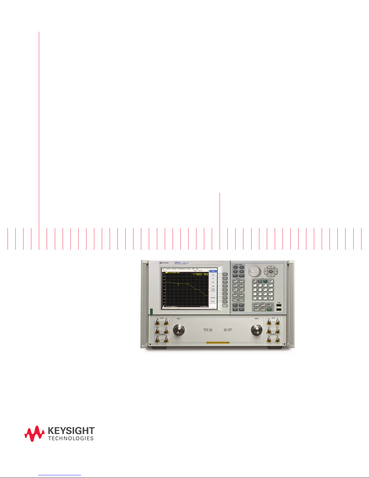
PNA Series Network Analyzer
The microwave PNA Series instruments are integrated vector network
analyzers equipped with a built-in S-parameter test set, synthesized
source, a hard disk drive, USB interfaces, and an 8.4” LCD color
touch screen display. The E8362C has 3.5 mm male 50-ohm test
ports. The E8363C/64C have 2.4 mm male 50-ohm test ports. The
E8361C has 1.85 mm male 50-ohm test ports. Included with each
instrument is a mouse and a keyboard (U.S.)
Test set and power configuration options
□ Configurable test set (Option 014)
Provides six front panel access loops. Three access loops are
for port one and three for port two. The loops provide access
to the signal path between (a) the source output and the
reference receiver, (b) the source output and directional coupler
thru arm and (c) the coupled arm of the directional coupler and
the port receiver. This option provides the capability to improve
instrument sensitivity for measuring low-level signals, to
reverse the directional coupler to achieve even more dynamic
range or to add components and other peripheral instruments
for a variety of measurement applications. (see PNA Series
Microwave Data Sheet literature number 5989-7605EN for a
basic block diagram)
□ Extended power range and bias-tees
(Option UNL)
Adds two 60 dB step attenuators and two bias-tees to the
E8362/3/4C. Adds two 50 dB step attenuators and two bias-tees
to the E8361C. A step attenuator and bias-tee set is inserted
between the source and test port one and another set
between the source and test port two. (see PNA Series
Microwave Data Sheet literature number 5989-7605EN for a
basic block diagram)
□ Add receiver attenuators (Option 016)
An attenuator is added between each test port and its
corresponding receiver. Two 35 dB step attenuators are added
to the E8362/3/4C. Two 50 dB step attenuators are added to
the E8361C (see PNA Series Microwave Data Sheet literature
number 5989-7605EN for a basic block diagram).
□ High-power test set (Model E836xCH85)
This configuration combines options that are often necessary
for high power measurements (UNL1, 014, 016, 080, 081).
The only difference between ordering Option H85 versus a
combination of the options listed above is the source
attenuator option UNL. Standard UNL includes two source
attenuators and two bias-tees. Option H85 includes the two
source attenuators, but not the bias-tees, as the bias-tees are
the power-limiting factor in the network analyzer test set. The
maximum power at the test port is +43 dBm (< 20 GHz), and
+40 dBm (> 20 GHz).
Option 080, frequency-offset mode, is included in Option H85
because it manages the phase-locking internally (instead of
depending on the R1 receiver). So if you need to use external
components in the path of the R1 receiver, it makes the
measurements simpler and more robust.
Measurement applications
□ Time-domain capability (Option 010)
For viewing reflection and transmission responses in time or
distance domain.
□ Frequency offset (Option 080)
This option enables the PNA Series microwave network analyzers
to set the source frequency independently from where the
receivers are tuned. This ability is important for two general
classes of devices: mixers (and converters) and amplifiers.
Option 080 provides a very basic user interface.
□ Reference receiver switch (Option 081)
Option 081 adds a solid-state internal RF transfer switch in the
R1 reference-receiver path (see PNA Series Microwave Data
Sheet literature number 5989-7605EN for a block diagram). The
switch allows the instrument to easily switch between standard
S-parameter (non-frequency-offset) measurements and frequency
offset measurements such as relative phase or absolute group
delay that require an external reference mixer. The user can set
the switch manually or remotely, but it is best used with the
frequency-converter application (Option 083), where it is controlled
automatically during the vector-mixer calibration procedure
and subsequent measurements.
□ Scalar-calibrated converter measurements
(Option 082)
With a simple setup and calibration, this application provides
the highest accuracy for conversion-loss (or gain) measurements
by combining one-por t and power-meter calibrations to remove
mismatch errors. Option 080 required.
□ Vector- and scalar-calibrated converter
measurements (Option 083)
This converter measurement adds an intuitive and easy-to-use
user interface, advanced calibration choices that provide
exceptional amplitude and phase accuracy, and control of
external signal sources for use as local oscillators. Mixer
calibration techniques include scalar-mixer calibration and
vector-mixer calibration (requires Option 081). Finally, the
frequency-converter application supports all of Keysight’s
major signal source families.
□ Embedded LO Measurements (Option 084)
This option tunes the PNA receivers to the output frequency of
the converter under test, without the need for access to internal
LOs or a common reference signal. For converters with embed-
ded LOs, this option enables measurements of match-corrected
conversion loss/gain (requires Option 082 or 083), and absolute
group delay (requires Option 083).
1. UNL does not include bias-tees. Only includes source attenuators
4

PNA Series Network Analyzer (continued)
□ 4-port measurement application
(Option 550)
Adds multiport analyzer mode to any PNA network analyzer
with Option 014 configurable test set, which enables full
4-port error correction and measurement capabilities using an
external test set. Only standard measurement class is available
in the multiport analyzer mode.
□ N-port capabilities (Option 551)
Adds multiport analyzer mode to any PNA network analyzer
with Option 014 configurable test set, which enables full
N-port error correction and measurement capabilities using
an external test set. Only standard measurement class is
available in the multiport analyzer mode.
Pulse, antenna, mm-wave
□ Pulsed-RF measurement capability
(Option H08)
Provides software to set up and control pulsed-RF measurements
with point-in-pulse capability. The software sets the coefficient
of the PNA’s digital-IF filter to null out unwanted spectral
components, enables the IF gates provided with IF access
(Option H11), and controls selected Keysight pulse generators.
It can be run on the PNA or an external computer. A “.dll” file
containing the IF-filter algorithms is included for automated
pulsed-RF testing. The pulsed application is configured to work
with the Keysight 81110A series pulse generator.
For more detailed information regarding pulsed measurement
capabilities with the microwave PNA refer to the Keysight
Web site www.keysight.com/find/pna and download the PNA
Series MW Network Analyzers Configuration Guide for Pulsed
Measurements, literature number 5989-7913EN.
Accessories
□ Rack mount kit without handles
(Option 1CM)
Adds a rack mount (5063-9217) and rail kit (E3663AC) for use
without handles.
□ Rack mount kit with handles (Option 1CP)
Adds a rack mount (5063-9237)1 and rail kit (E3663AC) for use
with standard supplied handles.
Configuration Details
Selecting the correct mixer-test
configuration:
Most mixer or converter test applications require Options 014, 080,
and 082 for conversion loss/gain, or Options 014, 080, 081 and 083
for conversion loss/gain and phase/delay measurements. If you want
to create and automate your own custom frequency-offset measurements (for example, intermodulation distortion),
you may only need Options 014 and 080. For converters that require
input power below -27 dBm, or for devices that have a large amount
of LO feedthrough (like an unltered mixer), Option UNL, which adds
source attenuators, is highly recommended. Besides allowing lower
input power levels, these attenuators improve the isolation between
the PNA’s internal source and
LO leakage signals, helping to prevent source-unleveled errors. For
devices that put out signals near or above the receiver’s compression
levels (which varies between –3 and +5 dBm, depending on the
model and frequency), Option 016 is recommended, which adds
receiver attenuators. Finally, Option 010, which adds time-domain
analysis, is very useful for gating out unwanted, time-delayed
responses which often occur when measuring mixers.
□ IF access (Option H11)
Provides hardware to enable antenna, point-in pulse, and
broadband millimeter-wave measurements to 110 GHz. For
each of the MW PNA’s measurement receivers, IF gates
(enabled with pulsed measurement capability, Option H08) and
external IF inputs are added. In addition, access to the PNA’s
internal RF and LO source is provided for remote mixing
applications. For basic antenna measurements, only Option H11
is necessary. Pulsed antenna applications also require the
pulsed measurement capability (Option H08). Broadband
measurements to 110 GHz, also requires an N5260A
millimeter-wave test set controller.
Note: Use external IF access for up to 20 dB more sensitivity
when making antenna measurements with a remote mixing
configuration. Add Option H08 (Pulsed-RF Measurement
Capability) to enable advanced pulsed measurements. Or
upgrade to a broadband (10 MHz to 110 GHz) VNA system
simply by purchasing an N5260A controller test set with test
heads (Option 110, 120, or 130).
1. The 5063-9237 kit assumes you have the standard handles
shipped with the instrument. If you do not have handles, order a
5063-9224 kit.
5
 Loading...