

Keysight P937 A Series, P9370A, P9372A, P9373A, P9374A Service Manual
...
Keysight P937xA Streamline Series USB
Vector Network Analyzers
P9370A, 300 kHz to 4 GHz
P9371A, 300 kHz to 6.5 GHz
P9372A, 300 kHz to 9 GHz
P9373A, 300 kHz to 14 GHz
P9374A, 300 kHz to 20 GHz
P9375A, 300 kHz to 26.5 GHz
Service Guide

Notices
© Keysight Technologies, Inc. 2019
No part of this manual may be
reproduced in any form or by any
means (including electronic storage
and retrieval or translation into a
foreign language) without prior
agreement and written consent from
Keysight Technologies, Inc. as
governed by United States and
international copyright laws.
Trademark Acknowledgments
Manual Part Number
P9370-90004
Edition
Edition 1, April 2019
Published in USA/Malaysia
Keysight Technologies Inc.
1400 Fountaingrove Parkway
Santa Rosa, CA 95403
Warranty
THE MATERIAL CONTAINED IN THIS
DOCUMENT IS PROVIDED “AS IS,”
AND IS SUBJECT TO BEING
CHANGED, WITHOUT NOTICE, IN
FUTURE EDITIONS. FURTHER, TO THE
MAXIMUM EXTENT PERMITTED BY
APPLICABLE LAW, KEYSIGHT
DISCLAIMS ALL WARRANTIES,
EITHER EXPRESS OR IMPLIED WITH
REGARD TO THIS MANUAL AND ANY
INFORMATION CONTAINED HEREIN,
INCLUDING BUT NOT LIMITED TO THE
IMPLIED WARRANTIES OF
MERCHANTABILITY AND FITNESS
FOR A PARTICULAR PURPOSE.
KEYSIGHT SHALL NOT BE LIABLE FOR
ERRORS OR FOR INCIDENTAL OR
CONSEQUENTIAL DAMAGES IN
CONNECTION WITH THE
FURNISHING, USE, OR
PERFORMANCE OF THIS DOCUMENT
OR ANY INFORMATION CONTAINED
HEREIN. SHOULD KEYSIGHT AND THE
USER HAVE A SEPARATE WRITTEN
AGREEMENT WITH WARRANTY
TERMS COVERING THE MATERIAL IN
THIS DOCUMENT THAT CONFLICT
WITH THESE TERMS, THE WARRANTY
TERMS IN THE SEPARATE
AGREEMENT WILL CONTROL.
Technology Licenses
The hardware and/or software
described in this document are
furnished under a license and may be
used or copied only in accordance
with the terms of such license.
U.S. Government Rights
The Software is “commercial
computer software,” as defined by
Federal Acquisition Regulation (“FAR”)
2.101. Pursuant to FAR 12.212 and
27.405-3 and Department of Defense
FAR Supplement (“DFARS”) 227.7202,
the U.S. government acquires
commercial computer software under
the same terms by which the software
is customarily provided to the public.
Accordingly, Keysight provides the
Software to U.S. government
customers under its standard
commercial license, which is
embodied in its End User License
Agreement (EULA), a copy of which
can be found at
http://www.keysight.com/find/sweula
The license set forth in the EULA
represents the exclusive authority by
which the U.S. government may use,
modify, distribute, or disclose the
Software. The EULA and the license
set forth therein, does not require or
permit, among other things, that
Keysight: (1) Furnish technical
information related to commercial
computer software or commercial
computer software documentation
that is not customarily provided to the
public; or (2) Relinquish to, or
otherwise provide, the government
rights in excess of these rights
customarily provided to the public to
use, modify, reproduce, release,
perform, display, or disclose
commercial computer software or
commercial computer software
documentation. No additional
government requirements beyond
those set forth in the EULA shall apply,
except to the extent that those terms,
rights, or licenses are explicitly
required from all providers of
commercial computer software
pursuant to the FAR and the DFARS
and are set forth specifically in writing
elsewhere in the EULA. Keysight shall
be under no obligation to update,
revise or otherwise modify the
Software. With respect to any
technical data as defined by FAR
2.101, pursuant to FAR 12.211 and
27.404.2 and DFARS 227.7102, the
U.S. government acquires no greater
than Limited Rights as defined in FAR
27.401 or DFAR 227.7103-5 (c), as
applicable in any technical data.
Safety Notices
A CAUTION notice denotes a hazard. It
calls attention to an operating
procedure, practice, or the like that, if
not correctly performed or adhered to,
could result in damage to the product
or loss of important data. Do not
proceed beyond a CAUTION notice
until the indicated conditions are fully
understood and met.
A WARNING notice denotes a hazard.
It calls attention to an operating
procedure, practice, or the like that, if
not correctly performed or adhered to,
could result in personal injury or
death. Do not proceed beyond a
WARNING notice until the indicated
conditions are fully understood and
met.

Where to Find the Latest Information
For the latest information about these products, including the P937xA Help System, instrument software upgrades,
application information, and product information, browse to one of the following URLs:
https://www.keysight.com/find/usb-vna
To receive the latest updates by email, subscribe to Keysight Email Updates at the following URL:
http://www.keysight.com/find/emailupdates
Information on preventing analyzer damage can be found at:
http://www.keysight.com/find/tips
Safety and regulatory information can be found in the Startup Guide, available online at:
http://literature.cdn.keysight.com/litweb/pdf/P9370-90001.pdf
Is your product software up-to-date?
Periodically, Keysight releases software updates to fix known defects and incorporate product enhancements. To search for
software updates for your product, go to the Keysight Technical Support website at:
https://www.keysight.com/find/usb-vna
3

4

Table of Contents
1. Safety and Regulatory Information
Information in This Chapter . . . . . . . . . . . . . . . . . . . . . . . . . . . . . . . . . . . . . . . . . . . . . . . . . . . . 9
Safety Symbols . . . . . . . . . . . . . . . . . . . . . . . . . . . . . . . . . . . . . . . . . . . . . . . . . . . . . . . . . . . . . 10
General Safety Considerations. . . . . . . . . . . . . . . . . . . . . . . . . . . . . . . . . . . . . . . . . . . . . . . . . 11
Before Applying Power . . . . . . . . . . . . . . . . . . . . . . . . . . . . . . . . . . . . . . . . . . . . . . . . . . . . 11
Servicing . . . . . . . . . . . . . . . . . . . . . . . . . . . . . . . . . . . . . . . . . . . . . . . . . . . . . . . . . . . . . . . 11
Operating Conditions . . . . . . . . . . . . . . . . . . . . . . . . . . . . . . . . . . . . . . . . . . . . . . . . . . . . . 11
Electrostatic Discharge Protection. . . . . . . . . . . . . . . . . . . . . . . . . . . . . . . . . . . . . . . . . . . . . . 12
Inspect for Damage . . . . . . . . . . . . . . . . . . . . . . . . . . . . . . . . . . . . . . . . . . . . . . . . . . . . . . 13
Regulatory Information . . . . . . . . . . . . . . . . . . . . . . . . . . . . . . . . . . . . . . . . . . . . . . . . . . . . . . 14
Instruction for Use . . . . . . . . . . . . . . . . . . . . . . . . . . . . . . . . . . . . . . . . . . . . . . . . . . . . . . . 14
EMC . . . . . . . . . . . . . . . . . . . . . . . . . . . . . . . . . . . . . . . . . . . . . . . . . . . . . . . . . . . . . . . . . . 14
Safety . . . . . . . . . . . . . . . . . . . . . . . . . . . . . . . . . . . . . . . . . . . . . . . . . . . . . . . . . . . . . . . . . 15
Instrument Markings . . . . . . . . . . . . . . . . . . . . . . . . . . . . . . . . . . . . . . . . . . . . . . . . . . . . . 16
For the AC/DC Adapter . . . . . . . . . . . . . . . . . . . . . . . . . . . . . . . . . . . . . . . . . . . . . . . . . . . 17
Declaration of Conformity . . . . . . . . . . . . . . . . . . . . . . . . . . . . . . . . . . . . . . . . . . . . . . . . . 20
Equipment Ratings. . . . . . . . . . . . . . . . . . . . . . . . . . . . . . . . . . . . . . . . . . . . . . . . . . . . . . . 20
Environmental Conditions (Operating). . . . . . . . . . . . . . . . . . . . . . . . . . . . . . . . . . . . . . . . 20
Contents
2. General Product Information
Information in This Chapter . . . . . . . . . . . . . . . . . . . . . . . . . . . . . . . . . . . . . . . . . . . . . . . . . . . 19
Maintenance . . . . . . . . . . . . . . . . . . . . . . . . . . . . . . . . . . . . . . . . . . . . . . . . . . . . . . . . . . . . . . . 20
Analyzer Options, Accessories, and Upgrades Available. . . . . . . . . . . . . . . . . . . . . . . . . . . . . 21
Keysight Support, Services, and Assistance . . . . . . . . . . . . . . . . . . . . . . . . . . . . . . . . . . . . . . 22
Service and Support Options . . . . . . . . . . . . . . . . . . . . . . . . . . . . . . . . . . . . . . . . . . . . . . . 22
Contacting Keysight . . . . . . . . . . . . . . . . . . . . . . . . . . . . . . . . . . . . . . . . . . . . . . . . . . . . . . 22
Shipping Your Network Analyzer for Service or Repair . . . . . . . . . . . . . . . . . . . . . . . . . . . 22
3. Tests, Adjustments, and Troubleshooting
Information in This Chapter . . . . . . . . . . . . . . . . . . . . . . . . . . . . . . . . . . . . . . . . . . . . . . . . . . . 25
Before You Begin . . . . . . . . . . . . . . . . . . . . . . . . . . . . . . . . . . . . . . . . . . . . . . . . . . . . . . . . . . . 27
Get the Hardware Required for your GPIB Instruments . . . . . . . . . . . . . . . . . . . . . . . . . . 27
Verify the Operating Environment . . . . . . . . . . . . . . . . . . . . . . . . . . . . . . . . . . . . . . . . . . . 27
Protect Against Electrostatic Discharge (ESD) . . . . . . . . . . . . . . . . . . . . . . . . . . . . . . . . . 27
Allow the Analyzer to Warm Up. . . . . . . . . . . . . . . . . . . . . . . . . . . . . . . . . . . . . . . . . . . . . 27
Review the Principles of Connector Care. . . . . . . . . . . . . . . . . . . . . . . . . . . . . . . . . . . . . . 27
About System Verification and Performance Tests . . . . . . . . . . . . . . . . . . . . . . . . . . . . . . . . . 28
System Specifications . . . . . . . . . . . . . . . . . . . . . . . . . . . . . . . . . . . . . . . . . . . . . . . . . . . . 28
Keysight P937xA PXIe Service Guide 5

Contents
Instrument Specifications . . . . . . . . . . . . . . . . . . . . . . . . . . . . . . . . . . . . . . . . . . . . . . . . . .29
System Verification Procedure . . . . . . . . . . . . . . . . . . . . . . . . . . . . . . . . . . . . . . . . . . . . . . 29
Performance Tests . . . . . . . . . . . . . . . . . . . . . . . . . . . . . . . . . . . . . . . . . . . . . . . . . . . . . . . .29
Certificate of Calibration . . . . . . . . . . . . . . . . . . . . . . . . . . . . . . . . . . . . . . . . . . . . . . . . . . .30
ANSI/NCSL Z540.3-2006 and ISO/IEC 17025 Verification . . . . . . . . . . . . . . . . . . . . . . . . . . .31
Non-Standards Compliant Verification . . . . . . . . . . . . . . . . . . . . . . . . . . . . . . . . . . . . . . . . . . .32
Preliminary Checks . . . . . . . . . . . . . . . . . . . . . . . . . . . . . . . . . . . . . . . . . . . . . . . . . . . . . . . . . . 33
The Operator’s Check . . . . . . . . . . . . . . . . . . . . . . . . . . . . . . . . . . . . . . . . . . . . . . . . . . . . .33
System Verification . . . . . . . . . . . . . . . . . . . . . . . . . . . . . . . . . . . . . . . . . . . . . . . . . . . . . . . . . .36
What the System Verification Verifies. . . . . . . . . . . . . . . . . . . . . . . . . . . . . . . . . . . . . . . . .36
Measurement Uncertainty. . . . . . . . . . . . . . . . . . . . . . . . . . . . . . . . . . . . . . . . . . . . . . . . . .36
Measurement Traceability . . . . . . . . . . . . . . . . . . . . . . . . . . . . . . . . . . . . . . . . . . . . . . . . . .37
Performing System Verification. . . . . . . . . . . . . . . . . . . . . . . . . . . . . . . . . . . . . . . . . . . . . . 38
Test Management Environment (TME) Performance Tests . . . . . . . . . . . . . . . . . . . . . . . . . . . .45
Guidelines for Ordering Power-Sensor Calibration Service . . . . . . . . . . . . . . . . . . . . . . . .46
Adjustments. . . . . . . . . . . . . . . . . . . . . . . . . . . . . . . . . . . . . . . . . . . . . . . . . . . . . . . . . . . . . . . . 48
10 MHz Frequency Reference Adjustment . . . . . . . . . . . . . . . . . . . . . . . . . . . . . . . . . . . . .48
Source Adjustment . . . . . . . . . . . . . . . . . . . . . . . . . . . . . . . . . . . . . . . . . . . . . . . . . . . . . . .49
Receiver Adjustment . . . . . . . . . . . . . . . . . . . . . . . . . . . . . . . . . . . . . . . . . . . . . . . . . . . . . .50
Troubleshooting . . . . . . . . . . . . . . . . . . . . . . . . . . . . . . . . . . . . . . . . . . . . . . . . . . . . . . . . . . . . .51
Check the Basics . . . . . . . . . . . . . . . . . . . . . . . . . . . . . . . . . . . . . . . . . . . . . . . . . . . . . . . . .51
4. Replaceable Parts Listings
Information in This Chapter. . . . . . . . . . . . . . . . . . . . . . . . . . . . . . . . . . . . . . . . . . . . . . . . . . . .53
Ordering Information . . . . . . . . . . . . . . . . . . . . . . . . . . . . . . . . . . . . . . . . . . . . . . . . . . . . . . . . . 54
Assembly Replacement Procedure . . . . . . . . . . . . . . . . . . . . . . . . . . . . . . . . . . . . . . . . . . . . . .55
Replaceable Parts Listings . . . . . . . . . . . . . . . . . . . . . . . . . . . . . . . . . . . . . . . . . . . . . . . . . . . .56
Entire Analyzer. . . . . . . . . . . . . . . . . . . . . . . . . . . . . . . . . . . . . . . . . . . . . . . . . . . . . . . . . . .56
Miscellaneous Parts. . . . . . . . . . . . . . . . . . . . . . . . . . . . . . . . . . . . . . . . . . . . . . . . . . . . . . .58
Accessories Part . . . . . . . . . . . . . . . . . . . . . . . . . . . . . . . . . . . . . . . . . . . . . . . . . . . . . . . . .59
5. Removal and Replacement Procedures
Information in This Chapter. . . . . . . . . . . . . . . . . . . . . . . . . . . . . . . . . . . . . . . . . . . . . . . . . . . .61
Electrostatic Discharge (ESD) Protection . . . . . . . . . . . . . . . . . . . . . . . . . . . . . . . . . . . . . . . . .62
Connector Replacement Procedure . . . . . . . . . . . . . . . . . . . . . . . . . . . . . . . . . . . . . . . . . . . . . 63
Parts Required. . . . . . . . . . . . . . . . . . . . . . . . . . . . . . . . . . . . . . . . . . . . . . . . . . . . . . . . . . .63
Tools Required . . . . . . . . . . . . . . . . . . . . . . . . . . . . . . . . . . . . . . . . . . . . . . . . . . . . . . . . . . .63
Removal Procedure . . . . . . . . . . . . . . . . . . . . . . . . . . . . . . . . . . . . . . . . . . . . . . . . . . . . . . .63
Replacement Procedure . . . . . . . . . . . . . . . . . . . . . . . . . . . . . . . . . . . . . . . . . . . . . . . . . . .64
Front Panel Replacement Procedure. . . . . . . . . . . . . . . . . . . . . . . . . . . . . . . . . . . . . . . . . . . . .65
6 Keysight P937xA PXIe Service Guide

Removing and Replacing the A3 Front Panel Assembly . . . . . . . . . . . . . . . . . . . . . . . . . . 65
Chassis Replacement Procedure . . . . . . . . . . . . . . . . . . . . . . . . . . . . . . . . . . . . . . . . . . . . . . . 68
Removing and Replacing the A1 Chassis . . . . . . . . . . . . . . . . . . . . . . . . . . . . . . . . . . . . . 68
Module Replacement Procedure . . . . . . . . . . . . . . . . . . . . . . . . . . . . . . . . . . . . . . . . . . . . . . . 71
Removing and Replacing the A2 Module Assembly . . . . . . . . . . . . . . . . . . . . . . . . . . . . . 71
Post-Repair Procedures . . . . . . . . . . . . . . . . . . . . . . . . . . . . . . . . . . . . . . . . . . . . . . . . . . . . . . 73
Ingot Chassis Utilities. . . . . . . . . . . . . . . . . . . . . . . . . . . . . . . . . . . . . . . . . . . . . . . . . . . . . 74
6. General Product Information
Information in This Chapter . . . . . . . . . . . . . . . . . . . . . . . . . . . . . . . . . . . . . . . . . . . . . . . . . . . 87
Error Terms . . . . . . . . . . . . . . . . . . . . . . . . . . . . . . . . . . . . . . . . . . . . . . . . . . . . . . . . . . . . . . . . 88
Using Error Terms as a Diagnostic Tool . . . . . . . . . . . . . . . . . . . . . . . . . . . . . . . . . . . . . . . 88
Performing Measurement Calibration . . . . . . . . . . . . . . . . . . . . . . . . . . . . . . . . . . . . . . . . 89
Using Flowgraphs to Identify Error Terms . . . . . . . . . . . . . . . . . . . . . . . . . . . . . . . . . . . . . 89
Manual Access to Error Terms . . . . . . . . . . . . . . . . . . . . . . . . . . . . . . . . . . . . . . . . . . . . . . 90
. . . . . . . . . . . . . . . . . . . . . . . . . . . . . . . . . . . . . . . . . . . . . . . . . . . . . . . . . . . . . . . . . . . . . . 91
Error Term Data . . . . . . . . . . . . . . . . . . . . . . . . . . . . . . . . . . . . . . . . . . . . . . . . . . . . . . . . . 92
Accessing the Keysight License Manager (KLM) and Installing Your License Files . . . . . . . . 95
Contents
Firmware Upgrades . . . . . . . . . . . . . . . . . . . . . . . . . . . . . . . . . . . . . . . . . . . . . . . . . . . . . . . . . 98
How to Check the Current Firmware Version . . . . . . . . . . . . . . . . . . . . . . . . . . . . . . . . . . 98
Keysight P937xA PXIe Service Guide 7

Contents
8 Keysight P937xA PXIe Service Guide

Safety and Regulatory Information
Information in This Chapter
Keysight P937xA PXIe Service Guide
1 Safety and Regulatory Information
Information in This Chapter
This chapter provides safety information that will help protect you and your
network analyzer. It also contains information that is required by various
government regulatory agencies.
Section Title Summary of Content
Safety Symbols Descriptions of CAUTION and WARNING symbols used
throughout this manual.
General Safety
Considerations
Electrostatic Discharge
Protection
Regulatory Information Definitions of instrument markings.
A list of safety points to consider when servicing your
network analyzer.
A discussion of electrostatic discharge (ESD) and related
recommendations and requirements for ESD protection.
Instructions for disposing of the analyzer’s lithium battery.
Start Page
page 10
page 11
page 12
page 14
9

1-
Safety and Regulatory Information
Safety Symbols
Safety Symbols
The following safety symbols are used throughout this manual. Familiarize
yourself with each of the symbols and its meaning before operating this
instrument.
Denotes a hazard. It calls attention to a procedure that, if not correctly
performed or adhered to, would result in damage to or destruction of the
product. Do not proceed beyond a caution note until the indicated
conditions are fully understood and met.
Denotes a hazard. It calls attention to a procedure which, if not correctly
performed or adhered to, could result in injury or loss of life. Do not
proceed beyond a warning note until the indicated conditions are fully
understood and met.
10 Keysight P937xA PXIe Service Guide
Safety and Regulatory Information
General Safety Considerations
General Safety Considerations
Before Applying Power
If this product is not used as specified, the protection provided by the
equipment could be impaired. This product must be used in a normal
condition (in which all means for protection are intact) only.
The measuring terminals on this instrument are designed to be used with
external signals described in Measurement Category I, but NOT with
external signals described in Categories II, III, and IV. The input of this
instrument cannot be connected to the mains.
The Mains wiring and connectors shall be compatible with the connector
used in the premise electrical system. Failure to ensure adequate earth
grounding by not using the correct components may cause product
damage, and serious injury.
Servicing
These servicing instructions are for use by qualified personnel only. To
avoid electrical shock, do not perform any servicing unless you are
qualified to do so.
Operating Conditions
Operator is responsible for maintaining safe operating conditions. To
ensure safe operating conditions, P937xAs should not be operated beyond
the full temperature range documented in the P937xA Data Sheet
(http://literature.cdn.keysight.com/litweb/pdf/5992-2765EN.pdf). Not
maintaining safe operating conditions can result in shorter P937xA
lifespans, improper P937xA performance, and user safety issues. If
P937xAs are allowed to exceed the specified full temperature range,
P937xA surface temperatures can cause discomfort or burns if touched. If
a P937xA exceeds the full temperature range, always allow it to cool
before touching it or removing it from the chassis.
This product is designed for use in Installation Category II and Pollution
Degree 2 environment.
Keysight P937xA PXIe Service Guide 11
1-
Safety and Regulatory Information
Electrostatic Discharge Protection
Electrostatic Discharge Protection
Most causes of instrument failure can be avoided if you will apply the
information in this section. PLEASE READ!
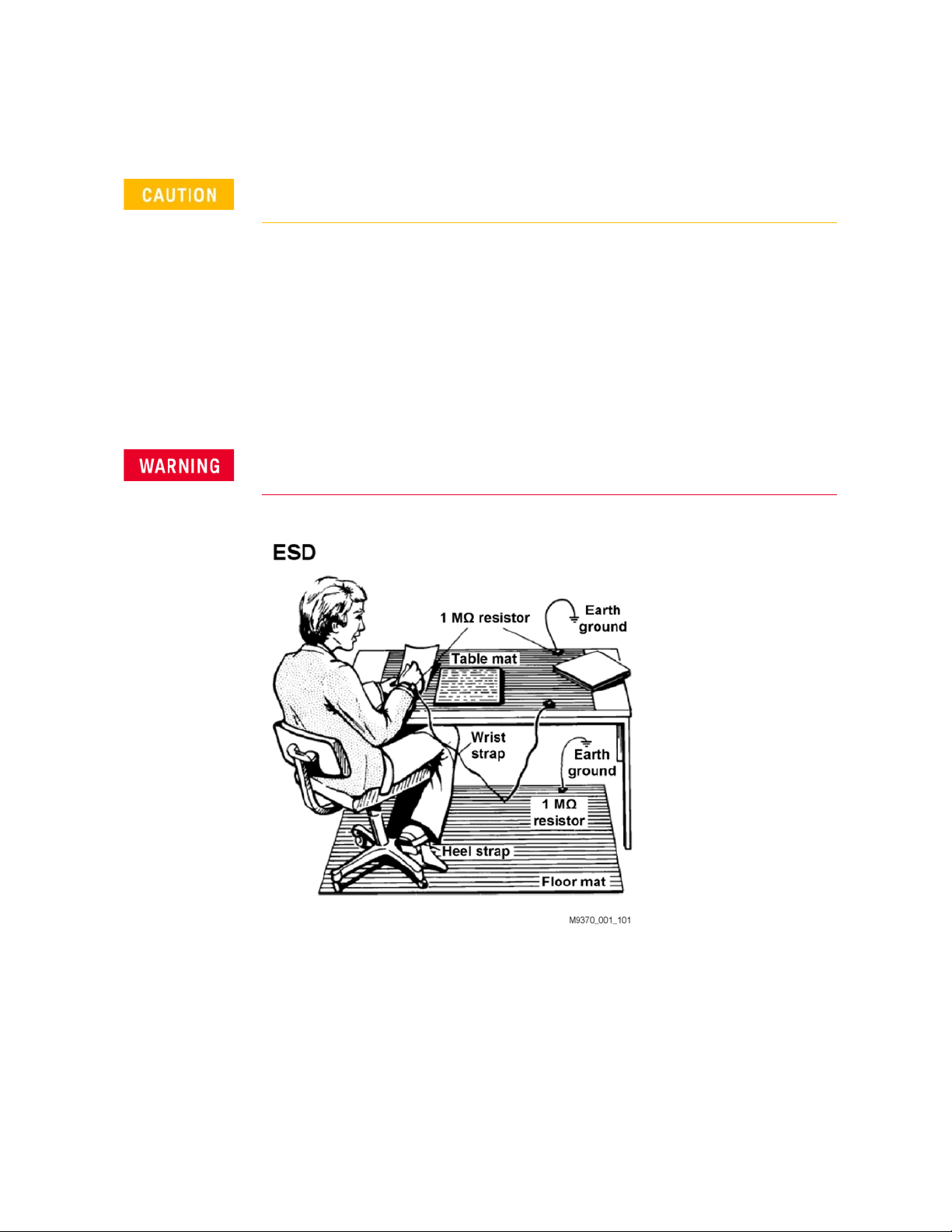
Electrostatic discharge (ESD) can damage or destroy electronic components.
Use a static-safe work station to perform all work on electronic assemblies.
Figure 1-1 on page 1-12 shows a static-safe work station using two types of
ESD protection: conductive table-mat and wrist-strap combination, and
conductive floor-mat and heel-strap combination. Both types, when used
together, provide a significant level of ESD protection. Of the two, only the
table-mat and wrist-strap combination provides adequate ESD protection
when used alone. To ensure user safety, the static-safe accessories must
provide at least 1 meg-ohm of isolation from ground.
Do NOT use these techniques for a static-safe work station when
working on circuitry with a voltage potential greater than 500 volts.
Figure 1-1 ESD protection setup
Unpack the P937xA network analyzer from the shipping containers. Keep the
black plastic port protectors and the shipping containers for possible reuse.
12 Keysight P937xA PXIe Service Guide

Safety and Regulatory Information
Electrostatic Discharge Protection
Inspect for Damage
After unpacking a network analyzer, inspect it for any shipping damage. Report
any damage to the shipping agent immediately, as such damage is not covered
by the warranty.
To avoid damage when handling the network analyzers, do not touch
exposed connector pins.
Keysight P937xA PXIe Service Guide 13
1-
Safety and Regulatory Information
Regulatory Information
Regulatory Information
This section contains information that is required by various government
regulatory agencies.
Instruction for Use
This product has been designed and tested in accordance with accepted
industry standards, and has been supplied in a safe condition. The
documentation contains information and warnings that must be followed by
the user to ensure safe operation and to maintain the product in a safe
condition.
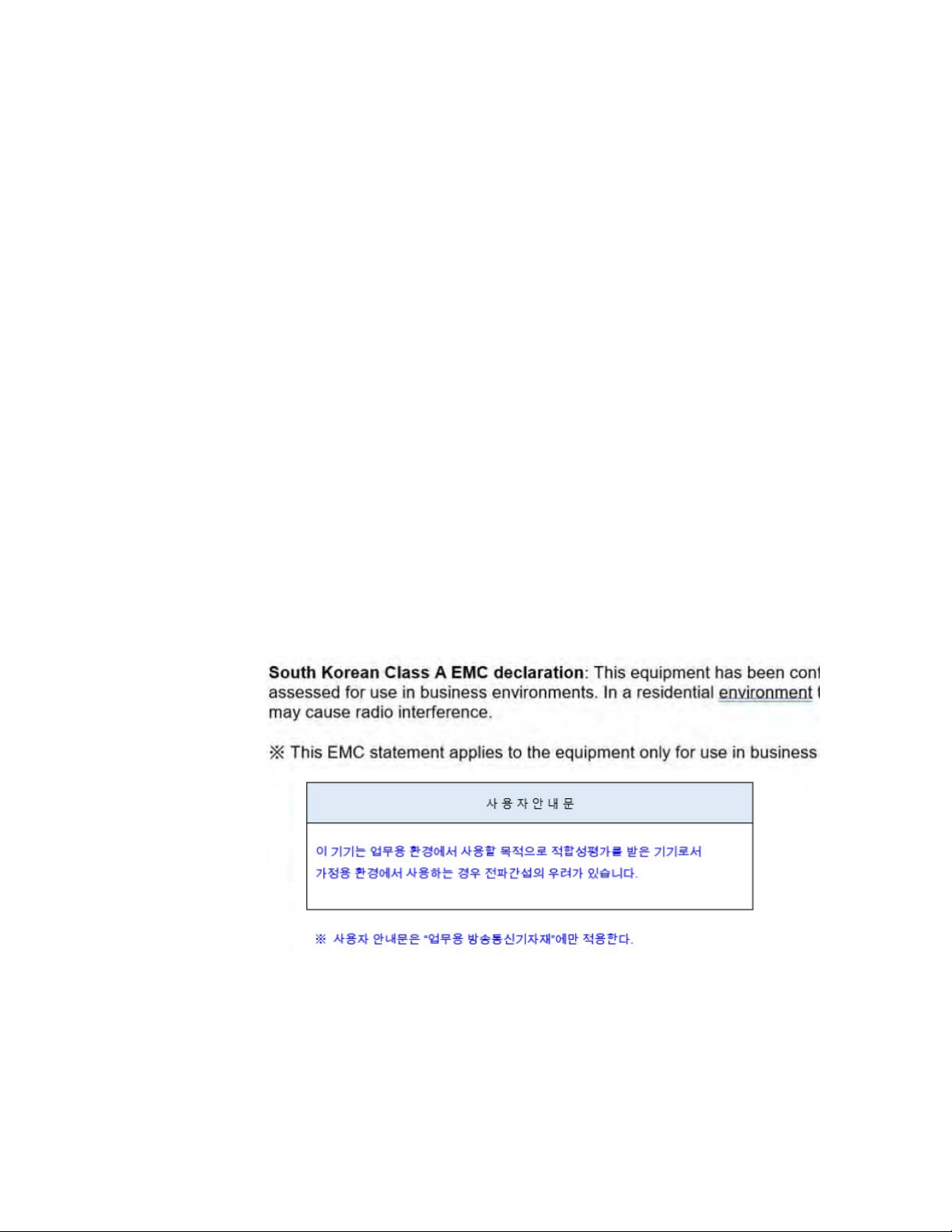
EMC
Complies with the essential requirements of the European EMC Directive as
well as current editions of the following standards (dates and editions are cited
in the Declaration of Conformity):
- IEC/EN 61326-1
- CISPR Pub 11 Group 1, class A
- AS/NZS CISPR 11
- ICES/NMB-001
This ISM device complies with Canadian ICES-001.
Cet appareil ISM est conforme a la norme NMB-001 du Canada.
14 Keysight P937xA PXIe Service Guide

Safety
Safety and Regulatory Information
Regulatory Information
Acoustic statement (European Machinery Directive)
- Acoustic noise emission
- LpA <70 dB
- Operator position
- Normal operation mode per ISO 7779
Complies with the following standard (dates and editions are cited in the
Declaration of Conformity): IEC/EN 61010-1.
Keysight P937xA PXIe Service Guide 15
1-
Safety and Regulatory Information
Regulatory Information
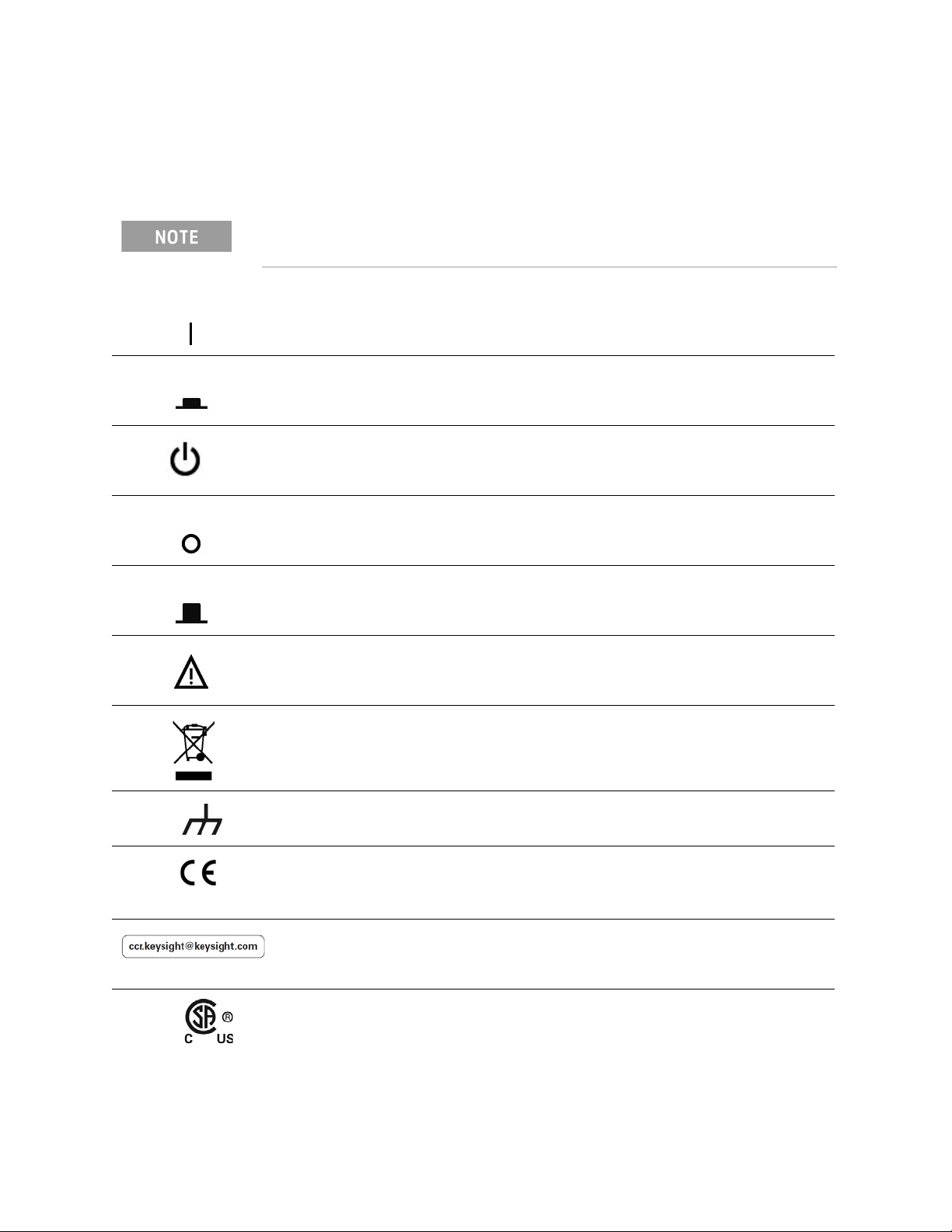
Instrument Markings
Some instrument markings may not appear on your analyzer.
This symbol marks the ON position of the power line switch.
This symbol marks the ON position of the power line switch.
This symbol marks the standby position of the power line switch.
This symbol marks the OFF position of the power line switch.
This symbol marks the OFF position of the power line switch.
The instruction documentation symbol. The product is marked with this symbol when it
is necessary for the user to refer to the instructions in the documentation.
This symbol indicates separate collection for electrical and electronic equipment,
mandated under EU law as of August 13, 2005. All electric and electronic equipment
are required to be separated from normal waste for disposal (Reference WEEE
Directive, 2002/96/EC).
This symbol is used to identify a terminal which is internally connected to the product
frame or chassis.
The CE mark is a registered trademark of the European Community (if accompanied by
a year, it is the year when the design was proven). This product complies with all
relevant directives.
The Keysight email address is required by EU directives applicable to our product.
The CSA mark is a registered trademark of the CSA International.
16 Keysight P937xA PXIe Service Guide
Safety and Regulatory Information
Regulatory Information
This is a symbol of an Industrial Scientific and Medical Group 1 Class A product.
(CISPR 11, Clause 5)
Direct current.
The RCM mark is a registered trademark of the Australian Communications and Media
Authority.
China Restricted Substance Product Label. The EPUP (environmental protection use
period) number in the center indicates the time period during which no hazardous or
toxic substances or elements are expected to leak or deteriorate during normal use
and generally reflects the expected useful life of the product.
ISO standard recycling symbol. This symbol satisfies the requirements for the China
standard GB 18455-2001 as required by the China RoHS regulations for
paper/fiberboard packaging.
South Korean Certification (KC) mark; includes the marking's identifier code
which follows this format: MSIP-REM-Kst-ZZZZZZZZZZZZZZ.
USB connectors.
Kensington security Lock.
For the AC/DC Adapter
For safety reasons, only equipment Keysight approved accessories should
be used with the instrument.
No operator serviceable parts inside. Refer servicing to qualified
personnel. To prevent electrical shock do not remove covers.
Use only the designated AC/DC adapter supplied with the instrument.
Use a Keysight supplied power cord that is the same or better electrical
rating.
Operated at an ambient temperature: 0 to 40°C.
(Linearly derate, at rate of 3 watts per degree C, from 90W at 40°C to 45 W
at 55°C, 30W at –20°C).
Maximum output rating: +15V/6.0 A.
Input rating: AC 100–240 V, 50–60Hz
Keysight P937xA PXIe Service Guide 17
1-
Safety and Regulatory Information
Regulatory Information
To prevent electrical shock, disconnect the AC to DC adapter from the
mains before cleaning. Use a dry cloth or one slightly dampened with
water to clean the external case parts. Do not attempt to cleans internally.
When the is connected to the AC/DC adapter, position the adapter so the
power cord is readily accessible. The power cord is the disconnecting
device. It removes main power to the AC/DC adapter. The front panel
switch is only for the DC power within the instrument, and not for the
AC/DC adapter. Alternately, an AC switch or circuit breaker (which is
readily identifiable and is easily reached by the operator) may be installed
and used as a disconnecting device to remove mains power from the
AC/DC adapter.
The AC/DC adapter has an auto–ranging line voltage input – be sure the
supply voltage is within the specified range.
The AC/DC adapter is for indoor use only.
Never use a modified or damaged charger. Use the original AC–DC
adapter ONLY.
The AC/DC adapter is designed for use in Installation Category II and
Pollution Degree 2 per IEC 61010-1.
18 Keysight P937xA PXIe Service Guide
Safety and Regulatory Information
Regulatory Information
Equipment Installation (AC/DC Adapter)
Use Keysight supplied power cord or one with same or better electrical
rating.
This instrument has auto-ranging line voltage input; be sure the supply
voltage is within the specified range and that voltage fluctuations do not to
exceed 10 percent of the nominal supply voltage.
Install the instrument so that the detachable power cord is readily
identifiable and is easily reached by the operator. The detachable power
cord is the instrument disconnecting device. It disconnects the mains
circuits from the mains supply before other parts of the instrument. The
front panel switch is only a standby switch and is not a LINE switch.
Alternatively, an externally installed switch or circuit breaker (which is
readily identifiable and is easily reached by the operator) may be used as a
disconnecting device.
Equipment Operation (AC/DC Adapter)
To prevent electrical shock, disconnect the Keysight Technologies P937xA
from mains before cleaning. Use a dry cloth or one slightly dampened with
water to clean the external case parts. Do not attempt to clean internally.
Position equipment to ensure easy access to disconnecting device.
Operator Equipment Maintenance and Service (AC/DC Adapter)
Use Keysight supplied power cord or one with same or better electrical
rating.
Keysight P937xA PXIe Service Guide 19

1-
Safety and Regulatory Information
Regulatory Information
Declaration of Conformity
A declaration of conformity is available upon request, or a copy is available on
the Keysight Technologies Web site at
http://www.keysight.com/go/conformity or by contacting Keysight - see
“Contacting Keysight” on page 22.
Equipment Ratings
The instruments can operate with mains supply voltage fluctuations up to
± 10% of the nominal voltage.
Instrument
DC input
External AC power adapter
Efficiency Level
Input 100 to 240 VAC,
Output 15 VDC ±5%, 6A max (90W max @40°C,
Power consumption (from the mains) 120V, 52 watts max
Environmental Conditions (Operating)
The instruments can operate with mains supply voltage fluctuations up to
± 10% of the nominal voltage.
Environmental Conditions (Operating)
For indoor use only
15 to 24 VDC
VI
50 to 60 Hz,
1.5 A to 0.75 A
linearly derate to 45W at 55°C)
240V, 62 watts max
Altitude up to: 3000m (9,842.2 ft)
Temperature: 0 to 55°C
Humidity:
Type tested at 95% RH, +40°C
20 Keysight P937xA PXIe Service Guide

General Product Information
Information in This Chapter
Keysight P937xA PXIe Service Guide
2 General Product Information
Information in This Chapter
Section Title Summary of Content
Maintenance Cleaning instructions for the external surfaces of your
network analyzer.
Information about electrical maintenance of your analyzer.
Analyzer Options,
Accessories, and Upgrades
Available
Keysight Support, Services,
and Assistance
A hyperlink to the network analyzer Configuration Guide,
which includes a list of options, accessories, and upgrades
available for the network analyzer.
The Internet address (URL) for Keysight assistance.
Service and support options available.
Calibration options available.
Important information about shipping your analyzer to
Keysight for service or repair.
Start Page
page 20
page 21
page 22
19

2-
General Product Information
Maintenance
Maintenance
To remove dirt or dust from the external case of the network analyzer P937xA,
clean the case using a dry or slightly-dampened cloth only.
To prevent electrical shock, remove analyzer module from chassis slot for
cleaning. Use a dry cloth or one slightly dampened with water to clean the
external case parts. Do not attempt to clean internally.
20 Keysight P937xA PXIe Service Guide

General Product Information
Analyzer Options, Accessories, and Upgrades Available
Analyzer Options, Accessories, and Upgrades Available
To see a list of the options, accessories, and upgrades available for the
network analyzers, including ordering information, refer to the Keysight PNA
Family Microwave Network Analyzers Configuration Guide, available online at
https://literature.cdn.keysight.com/litweb/pdf/5992-2823EN.pdf?id=29746
38
Keysight P937xA PXIe Service Guide 21

2-
General Product Information
Keysight Support, Services, and Assistance
Keysight Support, Services, and Assistance
Information on the following topics is included in this section.
— Service and Support Options
— Contacting Keysight
— Shipping Your Network Analyzer for Service or Repair
Service and Support Options
The network analyzer’s standard warranty is a 1-year return to Keysight
Technologies service warranty.
There are many other repair and calibration options available from the
Keysight Technologies support organization. These options cover a range
of service agreements with varying response times. Contact Keysight for
additional information on available service agreements for this product.
Refer to Contacting Keysight.
Contacting Keysight
Assistance with test and measurement needs and information on finding a
local Keysight office are available on the Web at:
www.keysight.com/find/assist
contact your Keysight field engineer.
. If you do not have access to the Internet, please
In any correspondence or telephone conversation, refer to the Keysight
product by its model number and full serial number. With this information,
the Keysight representative can determine whether your product is still
within its warranty period.
Shipping Your Network Analyzer for Service or Repair
Should it become necessary to return a network analyzer for repair or service,
follow the steps below:
1. Review the warranty information shipped with your product.
2. Contact Keysight to obtain a Return Material Authorization (RMA) and
return address. For assistance finding Keysight contact information, go to
www.keysight.com/find/assist (worldwide contact information for repair
and service).
3. Write the following information on a tag and attach it to the network
analyzer.
4. Name and address of owner. A P.O. box is not acceptable as a return
address.
22 Keysight P937xA PXIe Service Guide

General Product Information
Keysight Support, Services, and Assistance
5. network analyzer serial numbers. The serial number label is located on the
bottom panel of the module. The serial number can also be read from the
Soft Front Panel (SFP) interface, after the hardware is installed.
6. Description of the failure or service required.
7. On the shipping label, write ATTENTION REPAIR DEPARTMENT and the
RMA number.
8. Ship the analyzer module using the original packaging materials. Shipping
the analyzer module in anything other than the original packaging may
result in non-warranted damage.
Keysight P937xA PXIe Service Guide 23

2-
General Product Information
Keysight Support, Services, and Assistance
24 Keysight P937xA PXIe Service Guide

Tests, Adjustments, and Troubleshooting
Information in This Chapter
Keysight P937xA PXIe Service Guide
3 Tests, Adjustments, and Troubleshooting
Information in This Chapter
This chapter contains procedures to help you check, verify, adjust, and
troubleshoot your network analyzer.
— The checks verify the operation of the assemblies in your network analyzer.
— The verification compares the operation of your analyzer to a gold standard.
— The adjustments allow you to tune your network analyzer for best
performance.
— The troubleshooting assists you in finding the cause of a failure.
Section Title Summary of Content Start Page
Before You Begin Items to consider or procedures to perform before testing is
begun:
—Verify the Operating Environment.
—Protect Against Electrostatic Discharge.
—Allow the Analyzer to Warm Up.
—Review the Principles of Connector Care.
About System
Verification and
Performance Tests
ANSI/NCSL Z540.3-2006
and ISO/IEC 17025
Verification
Non-Standards
Compliant Verification
Descriptions of:
—System Specifications
—Instrument Specifications
—System Verification Procedure
—Performance Tests
—Certificate of Calibration
The ANSI/NCSL Z540.3-206 and ISO/IEC 17025 process of
verifying your network analyzer.
The Non-Standards Compliant process of verifying your
network analyzer.
page 27
page 28
page 31
page 32
25

3-
Tests, Adjustments, and Troubleshooting
Information in This Chapter
Section Title Summary of Content Start Page
Preliminary Checks Performing the Operator’s Check.
page 33
Checking your test cables.
NOTE Perform these checks before performing
system verification.
System Verification What the system verification does.
page 36
How to perform the verification test.
How to interpret the results.
Test Management
Environment (TME)
A list of equipment needed and TME webpage link
information.
page 45
Performance Tests
Troubleshooting A list of troubleshooting suggestions. page 51
26 Keysight P937xA PXIe Service Guide

Tests, Adjustments, and Troubleshooting
Before You Begin
Before You Begin
Before checking, verifying, or adjusting the analyzer, refer to the following
paragraphs to:
— get the required Service Test equipment
— make sure the operating environment is within its requirements
— make sure that proper electrostatic discharge (ESD) protection is provided
— make sure the analyzer has warmed up properly to achieve system stability
— review the principles of connector care
Get the Hardware Required for your GPIB Instruments
The hardware required to connect your GPIB instruments to the network
analyzer depends on the type of controller you use.
— Because the P937xA uses a remote controller, you need a GPIB card for the
PC.
Verify the Operating Environment
For Operating Environment information, refer to the online Data Sheet at
http://literature.cdn.keysight.com/litweb/5992-2765EN.pdf.
Protect Against Electrostatic Discharge (ESD)
For information on protecting against electrostatic discharge (ESD), refer to the
online Startup Guide at
http://literature.cdn.keysight.com/litweb/pdf/P9370-90001.pdf.
Allow the Analyzer to Warm Up
To achieve the maximum system stability, allow the network analyzer to
warm up for at least 15 minutes.
Review the Principles of Connector Care
For online information on connector care, go to
http://na.support.keysight.com/pna/connectorcare/Connector_Care.htm.
Keysight P937xA PXIe Service Guide 27

3-
Tests, Adjustments, and Troubleshooting
About System Verification and Performance Tests
About System Verification and Performance Tests
The performance of the network analyzer is specified in two ways: system
specifications and instrument specifications. It is the end user’s responsibility
to determine which set of specifications is applicable to their use of the
network analyzer.
A network analyzer measurement “system” includes the network analyzer,
calibration kit, test cables, and any necessary adapters. The system verification
software is used to verify the system’s conformance to the “system”
specifications. A “pass” result demonstrates that the network analyzer test
cables and adapters perform correctly as a system. It DOES NOT demonstrate
that any one component performs according to its individual specifications. A
change to any part of this measurement system requires a re-verification of the
system.
Instrument specifications specify the network analyzer’s uncorrected
measurement port characteristics and its output and input behavior. The
performance tests are used to verify the module’s conformance to “instrument”
specifications. Refer to “Test Management Environment (TME) Performance
Tests” on page 45.
System Specifications
System specifications specify warranted performance of the measurement
system when making error-corrected measurements using the same
calibration kit and test cables used during the system verifications routine.
System specifications are applicable only when the measurement system is
used to make error-corrected measurements.
The network analyzer’s system specifications are described in the Data Sheet,
available online at
http://literature.cdn.keysight.com/litweb/5992-2765EN.pdf.
System specifications are expressed in two ways:
— residual errors of the measurement system shown as tabular specification
values
— graphs of measurement uncertainty versus reflection and transmission
coefficients
System specifications are verified in one of the following ways:
— Complete the system verification procedure using a certified verification kit
and certified calibration kit that will be used for future measurements.
— Complete all of the performance tests using a certified calibration kit that
will be used for future measurements. This alternative verifies both the
system specifications and the instrument specifications for the network
analyzer.
28 Keysight P937xA PXIe Service Guide
 Loading...