

Page 1
Keysight Streamline Series
Vector Network Analyzers
P9370A, 300 kHz to 4.5 GHz
P9371A, 300 kHz to 6.5 GHz
P9372A, 300 kHz to 9 GHz
P9373A, 300 kHz to 14 GHz
P9374A, 300 kHz to 20 GHz
P9375A, 300 kHz to 26.5 GHz
Startup Guide
Page 2

Notices
© Keysight Technologies, Inc.
2014-2020
No part of this manual may be
reproduced in any form or by any
means (including electronic storage
and retrieval or translation into a
foreign language) without prior
agreement and written consent from
Keysight Technologies, Inc. as
governed by United States and
international copyright laws.
Trademark Acknowledgments
Manual Part Number
P9370-90001
Edition
Edition 1, September 2020
Printed in USA/Malaysia
Published by:
Keysight Technologies
1400 Fountaingrove Parkway
Santa Rosa, CA 95403
Warranty
THE MATERIAL CONTAINED IN THIS
DOCUMENT IS PROVIDED “AS IS,”
AND IS SUBJECT TO BEING
CHANGED, WITHOUT NOTICE, IN
FUTURE EDITIONS. FURTHER, TO
THE MAXIMUM EXTENT PERMITTED
BY APPLICABLE LAW, KEYSIGHT
DISCLAIMS ALL WARRANTIES,
EITHER EXPRESS OR IMPLIED WITH
REGARD TO THIS MANUAL AND
ANY INFORMATION CONTAINED
HEREIN, INCLUDING BUT NOT
LIMITED TO THE IMPLIED
WARRANTIES OF
MERCHANTABILITY AND FITNESS
FOR A PARTICULAR PURPOSE.
KEYSIGHT SHALL NOT BE LIABLE
FOR ERRORS OR FOR INCIDENTAL
OR CONSEQUENTIAL DAMAGES IN
CONNECTION WITH THE
FURNISHING, USE, OR
PERFORMANCE OF THIS
DOCUMENT OR ANY INFORMATION
CONTAINED HEREIN. SHOULD
KEYSIGHT AND THE USER HAVE A
SEPARATE WRITTEN AGREEMENT
WITH WARRANTY TERMS
COVERING THE MATERIAL IN THIS
DOCUMENT THAT CONFLICT WITH
THESE TERMS, THE WARRANTY
TERMS IN THE SEPARATE
AGREEMENT WILL CONTROL.
Technology Licenses
The hardware and/or software
described in this document are
furnished under a license and may be
used or copied only in accordance
with the terms of such license.
U.S. Government Rights
The Software is “commercial
computer software,” as defined
by Federal Acquisition Regulation
(“FAR”) 2.101. Pursuant to FAR
12.212 and 27.405-3 and
Department of Defense FAR
Supplement (“DFARS”) 227.7202,
the U.S. government acquires
commercial computer software
under the same terms by which
the software is customarily
provided to the public.
Accordingly, Keysight provides
the Software to U.S. government
customers under its standard
commercial license, which is
embodied in its End User License
Agreement (EULA), a copy of
which can be found at
http://www.keysight.com/find/sweula
The license set forth in the EULA
represents the exclusive authority
by which the U.S. government
may use, modify, distribute, or
disclose the Software. The EULA
and the license set forth therein,
does not require or permit,
among other things, that
Keysight: (1) Furnish technical
information related to
commercial computer software
or commercial computer
software documentation that is
not customarily provided to the
public; or (2) Relinquish to, or
otherwise provide, the
government rights in excess of
these rights customarily provided
to the public to use, modify,
reproduce, release, perform,
display, or disclose commercial
computer software or
commercial computer software
documentation. No additional
government requirements
beyond those set forth in the
EULA shall apply, except to the
extent that those terms, rights, or
licenses are explicitly required
from all providers of commercial
computer software pursuant to
the FAR and the DFARS and are
set forth specifically in writing
elsewhere in the EULA. Keysight
shall be under no obligation to
update, revise or otherwise
modify the Software. With
respect to any technical data as
defined by FAR 2.101, pursuant
to FAR 12.211 and 27.404.2 and
DFARS 227.7102, the U.S.
government acquires no greater
than Limited Rights as defined in
FAR 27.401 or DFAR 227.7103-5
(c), as applicable in any technical
data.
Safety Notices
A CAUTION notice denotes a hazard. It
calls attention to an operating
procedure, practice, or the like that,
if not correctly performed or adhered
to, could result in damage to the
product or loss of important data. Do
not proceed beyond a CAUTION
notice until the indicated conditions
are fully understood and met.
A WARNING notice denotes a hazard.
It calls attention to an operating
procedure, practice, or the like that,
if not correctly performed or adhered
to, could result in personal injury or
death. Do not proceed beyond a
WARNING notice until the indicated
conditions are fully understood and
met.
Page 3

Contents
1 . . . . . . . . . . . . . . . . . . . . . . . . . . . . . . . . . . . . . . . . . . . . . . . . . . . . . . . . . . . . . . . .Getting Started
Introduction 5
Related Documentation 5
STEP 1. Unpack and Inspect the P937xA Network Analyzer 5
Inspect for Damage 6
How to Return an Instrument for Service 6
STEP 2. Check the Shipment 7
S
EP 3. Install the Software 8
T
System Requirements 8
Hardware Requirements 8
About Installing the P937xA 8
Software Installation Overview 9
Power Up the Instrument with a PC 10
STEP 4. Install the P937xA Network
ools Required for the Installation Procedure 11
T
Analyzers 11
Installation Procedure 12
Front Panel Features 17
STEP 5. Verify Operation of the Netw
ork Analyzers 20
The Operator’s Check 20
If the Operator’s Check Fails 21
2
. . . . . . . . . . . . . . . . . . . . . . . . . . . . . . . .Getting Help with Your P937xA USB-Network Analyzer
Help System 1
P937xA on the Int
ernet 1
Contacting Keysight 2
3
. . . . . . . . . . . . . . . . . . . . . . . . . . . . . . . . . . . . . . . . . . . . . . . . Safety and Regulatory Information
Maintenance 1
Shipment for S
ervice 1
Safety Symbols 2
General Safety Considerations 3
Before Applying Power 3
Servicing 3
Operating Conditions 3
Keysight P937xA Startup Guide 3
Page 4

Contents
Regulatory Information 4
Instructions for Use 4
EMC 4
Safety 5
Instrument Markings 6
For the AC/DC Adapter 7
Declaration of Conformity 10
Equipment Ratings 11
Envir
nmental Conditions (Operating) 11
o
Space Requirements 12
P937xA VNA Weight and Dimensions 12
Component Weight and Dimensions 12
Warranty 12
4 Keysight P937xA Startup Guide
Page 5

Keysight Streamline Vector Network Analyzers
P937xA
Startup Guide
1 Getting Started
Introduction
The scope of this Startup Guide is to detail the processes of receiving and installing the
Keysight Streamline Series P937xA vector network analyzer (VNA) and cables that
compose the P937xA VNA. Additionally, installing the required software and verifying
P937xA vector network analyzer operation is documented. If you have any questions
after reviewing this information, please contact your local Keysight Technologies Inc.
representative or contact us through our support Website at
http://www.keysight.com/technicalsupport/main.
Related Documentation
You can find all P937xA network analyzer documentation and other resources
at https://www.keysight.com/find/usb-vna or at the respective product pages
on www.keysight.com (go to Resource Center > Manuals).
STEP 1. Unpack and Inspect the P937xA Network Analyzer
Most causes of instrument failure can be avoided if you will apply the
information in this section. PLEASE READ!
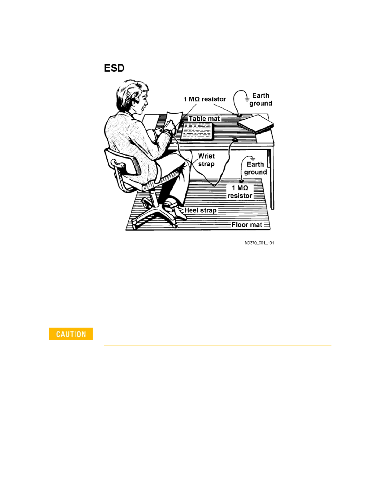
Electrostatic discharge (ESD) can damage or destroy electronic components.
Use a static-safe work station to perform all work on electronic assemblies.
Figure 1-1 on page 6 shows a static-safe work station using two types of ESD
protection: conductive table-mat and wrist-strap combination, and conductive
floor-mat and heel-strap combination. Both types, when used together,
provide a significant level of ESD protection. Of the two, only the table-mat and
wrist-strap combination provides adequate ESD protection when used alone.
To ensure user safety, the static-safe accessories must provide at least 1
meg-ohm of isolation from ground.
Do NOT use these techniques for a static-safe work station when
working on circuitry with a voltage potential greater than 500 volts.
1-5
Page 6
1-
Getting Started
STEP 1. Unpack and Inspect the P937xA Network Analyzer
Figure 1-1 ESD protection setup
Unpack the P937xA network analyzer from the shipping containers. Keep the
black plastic port protectors and the shipping containers for possible reuse.
Inspect for Damage
After unpacking a network analyzer, inspect it for any shipping damage. Report
any damage to the shipping agent immediately, as such damage is not covered
by the warranty.
To avoid damage when handling the network analyzers, do not touch
exposed connector pins.
How to Return an Instrument for Service
Should it become necessary to return a network analyzer for repair or service,
follow the steps below:
1. Review the warranty information shipped with your product.
2. Contact Keysight to obtain a Return Material Authorization (RMA) and
return address. For assistance finding Keysight contact information, go to
www.keysight.com/find/assist (worldwide contact information for repair
and service).
1-6 Keysight Technologies Startup Guide
Page 7
Getting Started
STEP 2. Check the Shipment
3. Write the following information on a tag and attach it to the network
yzer:
anal
— Name and address of owner. A P.O. box is not acceptable as a return
address.
— Network analyzer serial numbers. The serial number and host ID
labels are located on the bottom of the panel of the P937xA. The
serial number can also be read from the Soft Front Panel (SFP)
interface, after the
— Description of the service required or the failure.
4. On the shipping label, write ATTENTION REPAIR DEPARTMENT and the
RMA number.
5. Ship the analyzer using the original packaging materials. Shipping the
analyzer in anything other than the original packaging may result in
non-warranted damage.
In your correspondence, refer to the network analyzer by serial number
and by model number.
hardware is installed.
STEP 2. Check the Shipment
Use the Contents List in the shipping container and Tab le 1-1 to verify the
completeness of your shipment. If not complete, refer to “Contacting Keysight”
on page 2.
Table 1-1 P9375A-Kit Contents
Qty Description Part Number
1 External Power Supply Desktop adapter 90-264AC 15VDC 6A 90W 1950-6128
China RoHS Addendum for Network Analyzer
1
1 Keysight safety leaflet 9320-6797
1 Quick start guide P9370-90005
1 Cable-Assembly USB 3.0 Type-A Plug to Type-C Plug 1m-LG PVC
Black
9320-6674
P9375-60010
Keysight Technologies Startup Guide 1-7
Page 8

1-
Getting Started
STEP 3. Install the Software
STEP 3. Install the Software
System Requirements
Topic
Windows 7 and 10 Requirements
a
Operating system Windows 10 (64 bit)
Windows 7 (64 bit)
Processor speed Intel i5 6th Generation or newer / Intel Xeon E3 or v3 or newer
Available memory 4 GB minimum (16 GB recommended)
Available disk space 2.0 GB available drive space minimum
Display resolution 1024x768 minimum
USB USB 3.0 panel mount connector directly to Intel chipset.
a. Must install IO Libraries (IOLS 2018 Update 1). BenchVue and Connection Expert are optional
downloads.
Hardware Requirements
Top ic Requirements
Controllers (PC) Refer to the above table in “System Requirements”.
Latch keys (x4) and
jumpers(x3)—(Optional)
Option Y1701A – For Multi-port Configuration of P937xA
About Installing the P937xA
Products affected All P937xA vector network analyzers
Estimated installation time 2 hours
1-8 Keysight Technologies Startup Guide
Page 9

Getting Started
STEP 3. Install the Software
Software Installation Overview
The software installation includes the following items:
— Keysight IO Libraries Suite (IOLS 2018 Update 1 or greater
1
), which includes
the Keysight Connection Expert. Download the latest version at
www.keysight.com/find/iosuite.
Ensure that Keysight IO Libraries Suite IOLS 2018 Update 1 or greater
is loaded into your PC controller, before you connect and power up
the P937xA.
— Network analyzer instrument software, which includes the soft front panel
(SFP) software, device drivers (IVI-C and IVI-COM, and LabVIEW G), and
documentation for the P937xA V
ector Network Analyzers. Download the
latest version at http://www.keysight.com/technicalsupport/main. Enter
the model for your instrument and click Find.
Software Installation Procedure
IMPORTANT! Ensure your P937xA is powered down and not connected to
your PC and ensure that your PC is connected to the internet.
1. Install the Keysight IO Libraries Suite (IOLS 2018 Update 1 or greater) by
downloading it from www.keysight.com/find/iosuite. Follow the installer
prompts to install the IO libraries.
2. Install the network analyzer software by downloading it from
http://www.keysight.com/technicalsupport/main. Enter the model for
your instrument and click Find. Follow the installer prompts.
3. Complete the installation:
a. After the InstallShield Wizard has completed, click Finish.
b. Shut down the remote controller PC, using Start > Shut down.
c. Power down the P937xA.
d. Use the power button to power up the P937xA.
1. IO Libraries version 2018 update 1, version 18.1.23205.4 or greater. BenchVue and
Connection Expert are optional downloads.
Keysight Technologies Startup Guide 1-9
Page 10
1-
Getting Started
STEP 3. Install the Software
e. Power up the remote controller PC.
Check for software updates at:
http://www.keysight.com/technicalsupport/main. Enter the model for
your instrument and click Find. Follow t
he installer prompts.
Power Up the Instrument with a PC
IMPORTANT! Before connecting your P937xA to your PC, ensure that your
PC has the Keysight IO Libraries Suite (IOLS 2018 Update 1 or greater) and
the P937xA firmware loaded. If not, refer to “Software Installation
Overview” on page 9.
The following assumes you have previously loaded your firmware and IO
Libraries (IOLS 2018 Update 1 or greater
“Software Installation Overview” on page 9.
1
) onto your PC. If not, refer to the
If you have loaded the IO Libraries (IOLS 2018 Update 1 or greater) and the
P937xA firmware, complete the following steps:
STOP! If you have not installed the firmware and the IO Libraries (IOLS
2018 Update 1 or greater) into the PC controller, refer to “Software
Installation Overview” on page 9.
Before powering up the P937xA, ensure that the DC power connector is
securely seated.
Before powering up the P937xA, ensure the P937xA "USB 3.0 to host PC"
cable interface is connected to the PC controller. After your P937xA has
been initialized, you can disconnect and reconnect the USB cable per a
typical USB device’s behavior.
1. Install the cable interface between the PC and the chassis.
2. Power up the P937xA instrument.
3. Power up the PC.
4. Start the P937xA application software.
If your P937xA application software and P937xA does not behave as
expected with the newly installed IO Libraries and firmware, cycle power
on the P937xA.
1. IO Libraries version 2018 update 1, version 18.1.23205.4 or greater. BenchVue and
Connection Expert are optional downloads.
1-10 Keysight Technologies Startup Guide
Page 11

Getting Started
Fan Exhaust Side
Fan Intake Side
The P937xA VNA has the right side of the instrument dedicated to
air intake and the left side dedicated to air exhaust.
STEP 4. Install the P937xA Network Analyzers
STEP 4. Install the P937xA Network Analyzers
IMPORTANT!
Please review all safety information located in Chapter 3 before
proceeding with installing and using the network analyzer.
Figure 1-2 P937xA chassis air flow
Tools Required for the Installation Procedure
— Socket adapter (part number 5023-1450) - not supplied.
— Torque driver (for use with socket adapter), set to 8 lbf-in (0.91 N.m) - not
supplied.
— Cable removal tool (part number 5002-3361) - not supplied.
— T10 torque driver, set to 9 lbf-in (1.02 N.m) – not supplied.
Keysight Technologies Startup Guide 1-11
Page 12
1-
Getting Started
STEP 4. Install the P937xA Network Analyzers
Installation Procedure
Position the P937xA to provide ample space between the chassis fan
intake and exhaust vents. Blockage by walls or obstructions affects the air
flow needed for cooling. (Refer to Figure 1-2 on page 11 and to the P937xA
chassis “Space Requirements” on page 12 for more information about
cooling.)
IMPORTANT!
If you are using a multiport (stacked) configuration ensure you have the
correct primary P9
https://www.keysight.com/find/usb-vna (i.e., click on your USB-VNA
model > Resource Center > Manuals > USB VNA Help File and search for
the "Multiport and Multisite Configuration" topic (you will need to save the
file to your desktop to view the files)). See also, USB Chassis Soft Front
Panel Help File.
37xA assigned. Refer to,
This procedure assumes you have Option Y1701A latch keys and jumpers kit.
Learn more, refer to, “Hardware Requirements” on page 8.
1. If using only one P937xA module, leave the 50 ohm loads attached as
shown in Figure 1-3 on page 12.
Figure 1-3 Single P937xA Network Analyzer Module Configuration
In the following instructions, two P937xA network analyzer modules are
configured. Use these instructions as a general guide if installing a
different number of modules.
2. As seen in Figure 1-4 on page 13, each module is shipped with two
50 ohm loads attached to each module. To enable connections between
P937xAs, some of these loads must be removed. To remove the loads, use
the socket adapter, seen in Figure 1-5 on page 13, attached to the 8 lbf-in
(0.91 N.m) torque driver.
a. On the first P937xA, remove the 50 ohm load from the LO Out port.
Leave the load installed on the LO In port.
1-12 Keysight Technologies Startup Guide
Page 13

Getting Started
STEP 4. Install the P937xA Network Analyzers
b. On the second P937xA, remove the 50 ohm load from the LO In port.
Leave the load installed on the LO Out port.
c. Save the 50 ohm loads that were just removed for possible reuse in
another module configuration.
Figure 1-4 50 Ohm Loads Installed on the Network Analyzer Modules
Figure 1-5 Socket Adapter for 50 Ohm Loads (part number 5023-1450)
3. Remove the front and rear handles off of both P937xA VNAs using a T10
torx driver. Refer to Figure 1-6 and Figure 1-7 on page 15.
4. Set the front and rear handles aside for reuse. The screws will not be
reused.
5. Stack the two P937xA VNAs and then:
Refer to Figure 1-6 and Figure 1-7 on page 15 for these steps.
a. Attach the left front latch to the P937xAs.
b. Connect one of the front handles to the bottom P937xA, loosely
attach the handle with the 0515-0375 screws (x2).
c. Repeat for top left P937xA VNA handle.
d. Repeat steps a through c for the right side front of the P937xA VNA.
e. Repeat steps a through d for the rear latches and handles using
latches P9375-20018 (x2) and 0515-0664 screws (x4) and
f. Use a T10 torx torque driver to tighten front and rear handle screws
to 9 lb-ins.
Keysight Technologies Startup Guide 1-13
Page 14

1-
Getting Started
STEP 4. Install the P937xA Network Analyzers
Figure 1-6 Assemble front latches and screws (0515-0375 screws (x8) P9375-20017
(x2))
1-14 Keysight Technologies Startup Guide
Page 15

Getting Started
STEP 4. Install the P937xA Network Analyzers
Figure 1-7 Assemble rear latches and screws (0515-0664 screws (x8) and P9375-20018
rear latches (x2)
6. Install a semi-rigid cable (P9375-20014), seen in Figure 1-8, betwee
T
rig Out port and the Trig In port on each of the P937xA pairs (1 & 2).
7. Install a semi-rigid cable (P9375-20015), seen in Figure 1-8, betwee
R
ef In port and the Ref Out port on each of the P937xA pairs (1 & 2).
8. Tighten the semi-rigid cables using the socket adapter, seen in Figure
on pa
ge 13, attached to an 8 lbf-in (0.91 N.m) torque driver.
9. Install a semi-rigid cable (P9375-20013), seen in Figure 1-8, betwee
L
O In port and the LO Out port on each of the P937xA pairs (1 & 2).
Keysight Technologies Startup Guide 1-15
n the
n the
1-5
n the
Page 16

1-
P9375-20014
Trig In to Trig Out
P9375-20013
LO In to LO Out
(Install last)
P9375-20015
(Ref In to Ref Out)
Getting Started
STEP 4. Install the P937xA Network Analyzers
Figure 1-8 Installing Semi-Rigid Cables from Option Y1701A—P9375-20013,
P9375-20014, and P9375-20015
Figure 1-9 Cable Removal Tool (part number 5002-3361)
If applicable, use the socket adapter tool (5023-1450) to remove the SMA
jumper cable P9375-20013. And, use the (5002-3361) tool for
P9735-20014, and NP9375-20015 SMB jumper cables. See Figure 1-9 on
page 16.
You have now completed the hardware installation procedure.
1-16 Keysight Technologies Startup Guide
Page 17

Getting Started
STEP 4. Install the P937xA Network Analyzers
Front Panel Features
Figure 1-10 P937xA Front Panel
Feature Description Refer to Figure 1-10 on page 17.
Power LED OFF: Power supply is disconnected
Amber: Power supply is on, but the power button is off.
Green: Power is on.
Status LED OFF: Power supply off.
AMBER: Power supply on, but no firmware is not running.
GREEN: Power switch is on; Firmware is running; instrument is probably
idle (not sweeping/trigger is in Hold).
FLASHING GREEN: A sweep or measurement has been triggered.
RED: Last sweep had an error.
Port 1 APC 3.5 mm female connector. Sources stimulus signals for the DUT and
Port 2
LO In SMA female connector. If the network analyzer is not configured with
LO Out SMA female connector. If the network analyzer is not configured with
Ref In SMB male connector. A 10 MHz external reference signal supplied to this
Ref Out SMB male connector. Outputs a 10 MHz frequency reference signal for use
Trig In SMB male connector. Inputs a signal to trigger the network analyzer
receives response signals from the DUT. Frequency range is determined by
the network analyzer model.
another P937xA, the connector is terminated with a 50 ohm load. If the
P937xA network analyzer is configured with another P937xA, the
connector receives the LO signal from the configured P937xA network
analyzer.
another P937xA, the connector is terminated with a 50 ohm load. If the
P937xA network analyzer is configured with another P937xA, the
connector provides the LO signal to the configured P937xA network
analyzer.
port can be used as the instrument frequency reference instead of the
internal frequency reference. To activate this feature on the soft front panel,
select Utility > System > Configure > External Reference.
by other test equipment.
P937xA.
Keysight Technologies Startup Guide 1-17
Page 18

1-
Getting Started
STEP 4. Install the P937xA Network Analyzers
Trig Out SMB male connector. Outputs a signal either before or after a
measurement.
Trig Ready SMB male connector. Outputs a “READY’ signal to other devices.
1-18 Keysight Technologies Startup Guide
Page 19

Getting Started
STEP 4. Install the P937xA Network Analyzers
Figure 1-11 P937xA Rear Panel
Feature Description Refer to Figure 1-11 on page 19.
ESD ESD strap connect
2.0 USB
Type A
USB 2.0 Type A slot. These slots can be used to connect USB 2.0
compatible PC accessories: (USB memory, keyboard, and mouse)
Slots (x2)
USB 3.0
To Host PC
USB 3.0 Type C connector. This slot is used to connect your host PC to
your P937xA. Optional ability to mount your USB 3.0 Type C cable using
mountable connector.
10 MHz In SMB male connector. A 10 MHz external reference signal supplied to this
port will only allow cascading reference signals to the 10MHz Out on the
rear panel. The instrument will not lock to this signal.
10 MHz
Out
SMB male connector. This port will supply a 10 MHz (+/-25 ppm) reference
signal for a cascading reference signal. It is independent of the
instrument’s reference signal. Use the front panel Reference Out for an
instrument reference.
Power
Mini-DIN connector. Connect the P937xA power supply to this port.
15 VDC,
6A Max
Trig 1 and
Trig 2
SMB male connector(s). A trigger is a signal that causes the analyzer to
make a measurement sweep. The analyzer offers great flexibility in
configuring the trigger function. P937xA has Trigger 1 and Trigger 2
connectors. See also, the VNA Online Help
(http://www.keysight.com/find/usb-vna).
Lock Kensington security lock
Keysight Technologies Startup Guide 1-19
Page 20

1-
Getting Started
STEP 5. Verify Operation of the Network Analyzers
STEP 5. Verify Operation of the Network Analyzers
The Operator’s Check
Allow the P937xA network analyzer to warm up for at least one hour before
performing the Operator’s Check.
The operator’s check is a software driven test that checks the basic operation
of the assemblies in all of the measurement port signal paths. By performing
the operator’s check, the following are determined:
— attenuation ranges of all installed attenuators
— calibration of the receivers
— frequency response of the receivers
—phase lock
—noise floor and trace noise
—various voltages throughout the network analyzer
Accessories Used in the Operator’s Check
Male short(s) or open(s) from a 3.5 mm calibration kit.
Performing the Operator’s Check
Perform the Operator’s Check on each P937xA network analyzer in your
configuration.
1. On your PC screen, click the Network Analyzer icon.
2. Select a P937xA network analyzer in your configuration.
3. On the soft front panel, select Utility > System > Service > Verification >
Operator’s Check.
4. In the P937xA Operator’s Check dialog box (refer to Figure 1-12 on
page 21), under Configure, select either Prompt for attachment of
Short/Open, to pause at each step in the process to allow moving the
short/open to the appropriate port, or Shorts/Opens are attached to ALL
ports, to run through the test without stopping. Shorts and opens can be
mixed on the test ports.
5. Select Begin.
6. If shorts and opens are not connected to all ports, you will be prompted to
connect them as they are needed.
7. The result of the operator’s check will be shown as a PASS or FAIL next to
each test (refer to Figure 1-12 on page 21.
1-20 Keysight Technologies Startup Guide
Page 21

Getting Started
STEP 5. Verify Operation of the Network Analyzers
Figure 1-12 Operator’s Check Dialog Box
If the Operator’s Check Fails
1. Clean the test ports, and the open(s) or short(s). Torque to specification.
epeat the check.
R
2. If the check still fails, return the network analyzer to Keysight. See
eturn an Instrument for Service” on page 6.
to R
Keysight Technologies Startup Guide 1-21
“How
Page 22

1-
Getting Started
STEP 5. Verify Operation of the Network Analyzers
1-22 Keysight Technologies Startup Guide
Page 23

Keysight Streamline Vector Network Analyzers
P937xA
Startup Guide
2 Getting Help with Your P937xA USB-Network Analyzer
Help System
Use the Help System to quickly reference programming and user
documentation
To access Help:
— From the analyzer P937xA software
— On your PC screen, click the Network Analyzer icon.
— After making your analyzer P937xA configuration settings, click Help.—
Online go to http://www.keysight.com/find/usb-vna.
P937xA on the Internet
The P937xA Network Analyzer System Web page is another resource for help
with the analyzer P937xA. You can find all P937xA network analyzer
documentation and other resources at:
http://www.keysight.com/find/usb-vna
Check for software updates at:
http://www.keysight.com/technicalsupport/main. Enter the model for your
instrument and click Find
2-1
Page 24

2-
Getting Help with Your P937xA USB-Network Analyzer
Contacting Keysight
Contacting Keysight
Assistance with test and measurements needs and information on finding a
local Keysight office are available on the Web at:
www.keysight.com/find/assist.
If you do not have access to the Internet, please contact your Keysight field
engineer.
In any correspondence or telephone conversation, refer to the Keysight
product by its model number and full serial number. With this information,
the Keysight representative can determine whether your product is still
within its warranty period.
2-2 Keysight Technologies Startup Guide
Page 25

Keysight Streamline Vector Network Analyzers
M937xA
Startup Guide
3 Safety and Regulatory Information
IMPORTANT! The safety of any system incorporating the equipment is the
responsibility of the assembler of the system.
Maintenance
To remove dirt or dust from the external case of the network analyzer P937xA,
clean the case using a dry or slightly-dampened cloth only.
To prevent electrical shock, disconnect the AC/DC adapter from the
mains before cleaning. Use a dry cloth or one slightly dampened
with water to clean the external case parts. Do not attempt to clean
internally.
Shipment for Service
Contact Keysight Technologies for instructions on where to ship the analyzer
P937xA for service. Refer to “Contacting Keysight” on page 2.
Ship the analyzer P937xA using the original packaging materials. Shipping the
analyzer P937xA in anything other than the original packaging may result in
non-warranted damage.
3- 1
Page 26

3-
Safety and Regulatory Information
Safety Symbols
Safety Symbols
The following safety symbols are used throughout this manual. Familiarize
yourself with each of the symbols and its meaning before operating this
instrument.
Denotes a hazard. It calls attention to a procedure that, if not correctly
performed or adhered to, would result in damage to or destruction of the
product. Do not proceed beyond a caution note until the indicated
conditions are fully understood and met.
Denotes a hazard. It calls attention to a procedure which, if not
correctly performed or adhered to, could result in injury or loss of
life. Do not proceed beyond a warning note until the indicated
conditions are fully understood and met.
3-2 Keysight Technologies Startup Guide
Page 27

Safety and Regulatory Information
General Safety Considerations
General Safety Considerations
Before Applying Power
If this product is not used as specified, the protection provided by
the equipment could be impaired. This product must be used in a
normal condition (in which all means for protection are intact) only.
The measuring terminals on this instrument are designed to be used with
external signals described in Measurement Category I, but NOT with
external signals described in Categories II, III, and IV. The input of this
instrument cannot be connected to the mains.
The Mains wiring and connectors shall be compatible with the connector
used in the premise electrical system. Failure to ensure adequate earth
grounding by not using the correct components may cause product
damage, and serious injury.
Servicing
These servicing instructions are for use by qualified personnel only.
To avoid electrical shock, do not perform any servicing unless you
are qualified to do so.
Operating Conditions
Operator is responsible for maintaining safe operating conditions. To
ensure safe operating conditions, P937xAs should not be operated beyond
the full temperature range documented in the P937xA Data Sheet
(http://literature.cdn.keysight.com/litweb/pdf/5992-2765EN.pdf). Not
maintaining safe operating conditions can result in shorter P937xA
lifespans, improper P937xA performance, and user safety issues. If
P937xAs are allowed to exceed the specified full temperature range,
P937xA surface temperatures can cause discomfort or burns if touched. If
a P937xA exceeds the full temperature range, always allow it to cool
before touching it or removing it from the chassis.
This product is designed for use in Installation Category II and Pollution
Degree 2 environment.
Keysight Technologies Startup Guide 3-3
Page 28

3-
Safety and Regulatory Information
Regulatory Information
Regulatory Information
This section contains information that is required by various government
regulatory agencies.
Instructions for Use
This product has been designed and tested in accordance with accepted
industry standards, and has been supplied in a safe condition. The
documentation contains information and warnings that must be followed by
the user to ensure safe operation and to maintain the product in a safe
condition.
EMC
Complies with the essential requirements of the European EMC Directive as
well as current editions of the following standards (dates and editions are cited
in the Declaration of Conformity):
— IEC/EN 61326-1
— CISPR Pub 11 Group 1, class A
— AS/NZS CISPR 11
— ICES/NMB-001
This ISM device complies with Canadian ICES-001.
Cet appareil ISM est conforme a la norme NMB-001 du Canada.
3-4 Keysight Technologies Startup Guide
Page 29

Safety
Safety and Regulatory Information
Regulatory Information
Acoustic statement (European Machinery Directive)
— Acoustic noise emission
— LpA <70 dB
— Operator position
— Normal operation mode per ISO 7779
Complies with the following standard (dates and editions are cited in the
Declaration of Conformity): IEC/EN 61010-1.
Keysight Technologies Startup Guide 3-5
Page 30

3-
Safety and Regulatory Information
Regulatory Information
Instrument Markings
Some instrument markings may not appear on your analyzer.
This symbol marks the ON position of the power line switch.
This symbol marks the ON position of the power line switch.
This symbol marks the standby position of the power line switch.
This symbol marks the OFF position of the power line switch.
This symbol marks the OFF position of the power line switch.
The instruction documentation symbol. The product is marked with this symbol when it
is necessary for the user to refer to the instructions in the documentation.
This symbol indicates separate collection for electrical and electronic equipment,
mandated under EU law as of August 13, 2005. All electric and electronic equipment
are required to be separated from normal waste for disposal (Reference WEEE
Directive, 2002/96/EC).
This symbol is used to identify a terminal which is internally connected to the product
frame or chassis.
The CE mark is a registered trademark of the European Community (if accompanied by
a year, it is the year when the design was proven). This product complies with all
relevant directives.
The Keysight email address is required by EU directives applicable to our product.
The CSA mark is a registered trademark of the CSA International.
This is a symbol of an Industrial Scientific and Medical Group 1 Class A product.
(CISPR 11, Clause 5)
3-6 Keysight Technologies Startup Guide
Page 31

Safety and Regulatory Information
Regulatory Information
Direct current.
The RCM mark is a registered trademark of the Australian Communications and Media
Authority.
China Restricted Substance Product Label. The EPUP (environmental protection use
period) number in the center indicates the time period during which no hazardous or
toxic substances or elements are expected to leak or deteriorate during normal use
and generally reflects the expected useful life of the product.
ISO standard recycling symbol. This symbol satisfies the requirements for the China
standard GB 18455-2001 as required by the China RoHS regulations for
paper/fiberboard packaging.
South Korean Certification (KC) mark; includes the marking's identifier code
which follows this format: MSIP-REM-Kst-ZZZZZZZZZZZZZZ.
USB connectors.
Kensington security Lock.
For the AC/DC Adapter
For safety reasons, only equipment Keysight approved accessories
should be used with the instrument.
No operator serviceable parts inside. Refer servicing to qualified
personnel. To prevent electrical shock do not remove covers.
Use only the designated AC/DC adapter supplied with the
instrument.
Use a Keysight supplied power cord that is the same or better
electrical rating.
Operated at an ambient temperature: 0 to 40°C.
(Linearly derate, at rate of 3 watts per degree C, from 90W at 40°C
to 45 W at 55°C, 30W at –20°C).
Maximum output rating: +15V/6.0 A.
Input rating: AC 100–240 V, 50–60Hz
Keysight Technologies Startup Guide 3-7
Page 32

3-
Safety and Regulatory Information
Regulatory Information
To prevent electrical shock, disconnect the AC to DC adapter from
the mains before cleaning. Use a dry cloth or one slightly dampened
with water to clean the external case parts. Do not attempt to
cleans internally.
When the is connected to the AC/DC adapter, position the adapter
so the power cord is readily accessible. The power cord is the
disconnecting device. It removes main power to the AC/DC adapter.
The front panel switch is only for the DC power within the
instrument, and not for the AC/DC adapter. Alternately, an AC
switch or circuit breaker (which is readily identifiable and is easily
reached by the operator) may be installed and used as a
disconnecting device to remove mains power from the AC/DC
adapter.
The AC/DC adapter has an auto–ranging line voltage input – be sure the
supply voltage is within the specified range.
The AC/DC adapter is for indoor use only.
Never use a modified or damaged charger. Use the original AC–DC
adapter ONLY.
The AC/DC adapter is designed for use in Installation Category II and
Pollution Degree 2 per IEC 61010-1.
3-8 Keysight Technologies Startup Guide
Page 33

Safety and Regulatory Information
Regulatory Information
Equipment Installation (AC/DC Adapter)
Use a Keysight supplied power cord that is the same or better
electrical rating.
This instrument has auto-ranging line voltage input; be sure the supply
voltage is within the specified range and that voltage fluctuations do not to
exceed 10 percent of the nominal supply voltage.
Install the instrument so that the detachable power cord is readily
identifiable and is easily reached by the operator. The detachable power
cord is the instrument disconnecting device. It disconnects the mains
circuits from the mains supply before other parts of the instrument. The
front panel switch is only a standby switch and is not a LINE switch.
Alternatively, an externally installed switch or circuit breaker (which is
readily identifiable and is easily reached by the operator) may be used as a
disconnecting device.
Equipment Operation (AC/DC Adapter)
To prevent electrical shock, disconnect the Keysight Technologies
P937xA from mains before cleaning. Use a dry cloth or one slightly
dampened with water to clean the external case parts. Do not
attempt to clean internally.
Position equipment to ensure easy access to disconnecting device.
Operator Equipment Maintenance and Service (AC/DC Adapter)
Use Keysight supplied power cord or one with same or better
electrical rating.
Keysight Technologies Startup Guide 3-9
Page 34

3-
Safety and Regulatory Information
Regulatory Information
Declaration of Conformity
A declaration of conformity is available upon request, or a copy is available on
the Keysight Technologies Web site at
http://www.keysight.com/go/conformity or by contacting Keysight - see
“Contacting Keysight” on page 2.
3-10 Keysight Technologies Startup Guide
Page 35

Safety and Regulatory Information
Equipment Ratings
Equipment Ratings
The instruments can operate with mains supply voltage fluctuations up to
± 10% of the nominal voltage.
Instrument
DC input
External AC power adapter
Efficiency Level
Input 100 to 240 VAC,
Output
Power consumption (from the mains) 120V, 52 watts max
Environmental Conditions (Operating)
The instruments can operate with mains supply voltage fluctuations up to
± 10% of the nominal voltage.
Environmental Conditions (Operating)
15 to 24 VDC
VI
50 to 60 Hz,
1.5 A to 0.75 A
15 VDC ±5%, 6A max (90W max @40
linearly derate to 45W at 55
240V, 62 watts max
°C)
°C,
For indoor use only
Altitude up to: 3000m (9,842.2 ft)
Tempe rature:
Humidity:
◦
Type tested at 95% RH, +40
Keysight Technologies Startup Guide 3-11
C
0 to 55
◦
C
Page 36

3-
Safety and Regulatory Information
Space Requirements
Space Requirements
P937xA VNA Weight and Dimensions
Table 3-1
Model Weight Required Benchtop Dimensions for the System
2-Port
P937xA Weight and Clearance Requirements for Proper Cooling
Clearance Width Depth
1.9 kg (4.2 lbs) 5.0 cm (2.00 in) 27.94 cm (11.00 in) 40.64 cm (16.00 in)
Component Weight and Dimensions
Table 3-1 shows the maximum weight and dimensions of the P937xA system
components. Refer also to Table 3-2 on page 12 for P937xA VNA dimensions.
Table 3-2 P937xA VNA Weights and Dimensions – With Front and Rear Handles
Model Weight
P937xA, 2-Port VNA 1.9 kg
(4.2 lb)
nominal
Height Width Depth
4.79 cm
(1.89 in)
17.60 cm
(6.93 in)
33.27 cm
(13.10)
Warranty
The actual warranty on your instrument depends on the date it was ordered as
well as whether or not any warranty options were purchased at that time. To
determine the exact warranty on your instrument, contact Keysight
Technologies with the model and serial number of your instrument. Refer to
“Contacting Keysight” on page 2.
Keysight Technologies does not warrant third-party system-level (combination
of chassis, controllers, P937xAs, etc.) performance, safety, or regulatory
compliance, unless specifically stated.
3-12 Keysight Technologies Startup Guide
Page 37

Installation Note Xxxxx-xxxxx 3
Page 38

This information is subject to change
without notice.
© Keysight Technologies 2014-2020
Edition 1, September 2020
www.keysight.com
 Loading...