

Page 1

User's Guide
Keysight Technologies
FieldFox Analyzers
N9912A
Page 2

Notices
© Keysight Technologies, Inc. 2015,
2017
No part of this manual may be
reproduced in any form or by any
means (including electronic storage
and retrieval or translation into a
foreign language) without prior
agreement and written consent from
Keysight Technologies, Inc. as
governed by United States and
international copyright laws.
Trademark Acknowledgments
Manual Part Number
N9912-90001
Edition
Edition 2, March 2017
Supersedes: July 2016
Printed in USA/Malaysia
Published by:
Keysight Technologies
1400 Fountaingrove Parkway
Santa Rosa, CA 95403
Warranty
THE MATERIAL CONTAINED IN THIS
DOCUMENT IS PROVIDED “AS IS,”
AND IS SUBJECT TO BEING
CHANGED, WITHOUT NOTICE, IN
FUTURE EDITIONS. FURTHER, TO
THE MAXIMUM EXTENT PERMITTED
BY APPLICABLE LAW, KEYSIGHT
DISCLAIMS ALL WARRANTIES,
EITHER EXPRESS OR IMPLIED WITH
REGARD TO THIS MANUAL AND
ANY INFORMATION CONTAINED
HEREIN, INCLUDING BUT NOT
LIMITED TO THE IMPLIED
WARRANTIES OF
MERCHANTABILITY AND FITNESS
FOR A PARTICULAR PURPOSE.
KEYSIGHT SHALL NOT BE LIABLE
FOR ERRORS OR FOR INCIDENTAL
OR CONSEQUENTIAL DAMAGES IN
CONNECTION WITH THE
FURNISHING, USE, OR
PERFORMANCE OF THIS
DOCUMENT OR ANY INFORMATION
CONTAINED HEREIN. SHOULD
KEYSIGHT AND THE USER HAVE A
SEPARATE WRITTEN AGREEMENT
WITH WARRANTY TERMS
COVERING THE MATERIAL IN THIS
DOCUMENT THAT CONFLICT WITH
THESE TERMS, THE WARRANTY
TERMS IN THE SEPARATE
AGREEMENT WILL CONTROL.
Technology Licenses
The hardware and/or software
described in this document are
furnished under a license and may be
used or copied only in accordance
with the terms of such license.
U.S. Government Rights
The Software is “commercial
computer software,” as defined
by Federal Acquisition Regulation
(“FAR”) 2.101. Pursuant to FAR
12.212 and 27.405-3 and
Department of Defense FAR
Supplement (“DFARS”) 227.7202,
the U.S. government acquires
commercial computer software
under the same terms by which
the software is customarily
provided to the public.
Accordingly, Keysight provides
the Software to U.S. government
customers under its standard
commercial license, which is
embodied in its End User License
Agreement (EULA), a copy of
which can be found at
http://www.keysight.com/find/sweula
The license set forth in the EULA
represents the exclusive authority
by which the U.S. government
may use, modify, distribute, or
disclose the Software. The EULA
and the license set forth therein,
does not require or permit,
among other things, that
Keysight: (1) Furnish technical
information related to
commercial computer software
or commercial computer
software documentation that is
not customarily provided to the
public; or (2) Relinquish to, or
otherwise provide, the
government rights in excess of
these rights customarily provided
to the public to use, modify,
reproduce, release, perform,
display, or disclose commercial
computer software or
commercial computer software
documentation. No additional
government requirements
beyond those set forth in the
EULA shall apply, except to the
extent that those terms, rights, or
licenses are explicitly required
from all providers of commercial
computer software pursuant to
the FAR and the DFARS and are
set forth specifically in writing
elsewhere in the EULA. Keysight
shall be under no obligation to
update, revise or otherwise
modify the Software. With
respect to any technical data as
defined by FAR 2.101, pursuant
to FAR 12.211 and 27.404.2 and
DFARS 227.7102, the U.S.
government acquires no greater
than Limited Rights as defined in
FAR 27.401 or DFAR 227.7103-5
(c), as applicable in any technical
data.
Safety Notices
A CAUTION notice denotes a hazard. It
calls attention to an operating
procedure, practice, or the like that,
if not correctly performed or adhered
to, could result in damage to the
product or loss of important data. Do
not proceed beyond a CAUTION
notice until the indicated conditions
are fully understood and met.
A WARNING notice denotes a hazard.
It calls attention to an operating
procedure, practice, or the like that,
if not correctly performed or adhered
to, could result in personal injury or
death. Do not proceed beyond a
WARNING notice until the indicated
conditions are fully understood and
met.
Page 3

Contacting Keysight
Assistance with te
at: http://www.keysight.com/find/assist
If you do not have access to the Internet, please contract you Keysight field engineer.
in any correspondence or telephone conversation, refer to the Keysight product by its model number and full serial
number. With this information, the Keysight representative can determine whether you product is till within its warranty
period.
st and measurements needs and information on finding a local Keysight office are available on the Web
Where to Find the Latest Information
Documentation is updated periodically. For the latest information about these products, including instrument
software upgrades, application information, and product information, browse to one of the following URLs,
according to the name of your product:
http://www.keysight.com/find/fieldfox
To receive the latest updates by email, subscribe to Keysight Email Updates at the following URL:
http://www.keysight.com/find/MyKeysight
Information on preventing instrument damage can be found at:
www.keysight.com/find/PreventingInstrumentRepair
Is your product software up-to-date?
Periodically, Keysight releases software updates to fix known defects and incorporate product enhancements. To search
for software updates for your product, go to the Keysight Technical Support website at:
www.keysight.com/find/fieldfoxsupport
A.08.25 Firmware Release Updates (N991xA/2xA/3xA with serial number prefixes <5607)
For customers upgrading FieldFox firmware, the following is a list of changes from the previous release:
Updated LAN IP behavior:
“LAN Settings” on page 18-18
Other updates:
— pulse measurement mode offset value limit
— differential measurement impedance format calculation
— Recall functionality (N9912A only)
3
Page 4

A.09.50 Firmware Release Updates (Also, applies to N9912A units with serial number prefixes ≥5607)
For customers upgrading FieldFox firmware, the following is a list of changes from the previous release:
Added Real-Time Spectrum Analysis (RTSA) Mode - (
Option 350 does not apply to N9912A)
4
Page 5

Table of Contents
1. Overview
Options and Features
. . . . . . . . . . . . . . . . . . . . . . . . . . . . . . . . . . . . . . . . . . . . . . . . . . . . . . 1-1
Accessories . . . . . . . . . . . . . . . . . . . . . . . . . . . . . . . . . . . . . . . . . . . . . . . . . . . . . . . . . . . . . . . 1-3
FieldFox Manuals, Software, and Supplemental Help. . . . . . . . . . . . . . . . . . . . . . . . . . . . . . 1-4
Conventions that are used in the Manual . . . . . . . . . . . . . . . . . . . . . . . . . . . . . . . . . . . . 1-4
Safety Notes . . . . . . . . . . . . . . . . . . . . . . . . . . . . . . . . . . . . . . . . . . . . . . . . . . . . . . . . . . . 1-5
2. Preparing for Initial Use of Your New FieldFox
Check the Shipment . . . . . . . . . . . . . . . . . . . . . . . . . . . . . . . . . . . . . . . . . . . . . . . . . . . . . . . . 2-1
Meeting Power Requirements for the AC/DC Adapter . . . . . . . . . . . . . . . . . . . . . . . . . . . . . 2-1
Install the Lithium-Ion Battery . . . . . . . . . . . . . . . . . . . . . . . . . . . . . . . . . . . . . . . . . . . . . . . . 2-2
Battery Usage. . . . . . . . . . . . . . . . . . . . . . . . . . . . . . . . . . . . . . . . . . . . . . . . . . . . . . . . . . 2-2
FieldFox ON/OFF Settings . . . . . . . . . . . . . . . . . . . . . . . . . . . . . . . . . . . . . . . . . . . . . . . . . . . 2-3
Power Button LED Status. . . . . . . . . . . . . . . . . . . . . . . . . . . . . . . . . . . . . . . . . . . . . . . . . 2-4
FieldFox High Temperature Protection . . . . . . . . . . . . . . . . . . . . . . . . . . . . . . . . . . . . . . . . . 2-4
How to monitor the internal FieldFox temperature: . . . . . . . . . . . . . . . . . . . . . . . . . . . . 2-4
Temperature Control Mode . . . . . . . . . . . . . . . . . . . . . . . . . . . . . . . . . . . . . . . . . . . . . . . 2-5
High-Temp Shut down. . . . . . . . . . . . . . . . . . . . . . . . . . . . . . . . . . . . . . . . . . . . . . . . . . . 2-5
Avoid Overpowering the FieldFox . . . . . . . . . . . . . . . . . . . . . . . . . . . . . . . . . . . . . . . . . . . . . 2-5
Contents
Take the FieldFox Tour . . . . . . . . . . . . . . . . . . . . . . . . . . . . . . . . . . . . . . . . . . . . . . . . . . . . . . 2-7
Front Panel . . . . . . . . . . . . . . . . . . . . . . . . . . . . . . . . . . . . . . . . . . . . . . . . . . . . . . . . . . . . 2-7
Top Panel . . . . . . . . . . . . . . . . . . . . . . . . . . . . . . . . . . . . . . . . . . . . . . . . . . . . . . . . . . . . 2-10
Side Panel. . . . . . . . . . . . . . . . . . . . . . . . . . . . . . . . . . . . . . . . . . . . . . . . . . . . . . . . . . . . 2-10
Screen Tour . . . . . . . . . . . . . . . . . . . . . . . . . . . . . . . . . . . . . . . . . . . . . . . . . . . . . . . . . . 2-12
How to Enter Numeric Values . . . . . . . . . . . . . . . . . . . . . . . . . . . . . . . . . . . . . . . . . . . . . . . 2-14
Multiplier Abbreviations . . . . . . . . . . . . . . . . . . . . . . . . . . . . . . . . . . . . . . . . . . . . . . . . . 2-14
Connector Care. . . . . . . . . . . . . . . . . . . . . . . . . . . . . . . . . . . . . . . . . . . . . . . . . . . . . . . . . . . 2-15
3. CAT (Cable and Antenna Test) Mode
CAT Mode Settings . . . . . . . . . . . . . . . . . . . . . . . . . . . . . . . . . . . . . . . . . . . . . . . . . . . . . . . . . 3-3
How to select CAT Mode . . . . . . . . . . . . . . . . . . . . . . . . . . . . . . . . . . . . . . . . . . . . . . . . . 3-3
Measurement Selection . . . . . . . . . . . . . . . . . . . . . . . . . . . . . . . . . . . . . . . . . . . . . . . . . . 3-3
Quick Settings Table. . . . . . . . . . . . . . . . . . . . . . . . . . . . . . . . . . . . . . . . . . . . . . . . . . . . . 3-4
Frequency Range . . . . . . . . . . . . . . . . . . . . . . . . . . . . . . . . . . . . . . . . . . . . . . . . . . . . . . . 3-5
Scale Settings. . . . . . . . . . . . . . . . . . . . . . . . . . . . . . . . . . . . . . . . . . . . . . . . . . . . . . . . . . 3-5
Averaging . . . . . . . . . . . . . . . . . . . . . . . . . . . . . . . . . . . . . . . . . . . . . . . . . . . . . . . . . . . . . 3-6
Smoothing . . . . . . . . . . . . . . . . . . . . . . . . . . . . . . . . . . . . . . . . . . . . . . . . . . . . . . . . . . . . 3-7
Single or Continuous Measure. . . . . . . . . . . . . . . . . . . . . . . . . . . . . . . . . . . . . . . . . . . . . 3-7
Keysight N9912-90001 User’s Guide 5
Page 6

Contents
Resolution (Number of Data Points) . . . . . . . . . . . . . . . . . . . . . . . . . . . . . . . . . . . . . . . . . 3-8
Sweep Time . . . . . . . . . . . . . . . . . . . . . . . . . . . . . . . . . . . . . . . . . . . . . . . . . . . . . . . . . . . .3-8
Output Power. . . . . . . . . . . . . . . . . . . . . . . . . . . . . . . . . . . . . . . . . . . . . . . . . . . . . . . . . . .3-9
Interference Rejection . . . . . . . . . . . . . . . . . . . . . . . . . . . . . . . . . . . . . . . . . . . . . . . . . . . 3-10
Coupled Frequency . . . . . . . . . . . . . . . . . . . . . . . . . . . . . . . . . . . . . . . . . . . . . . . . . . . . . 3-11
Return Loss Measurements. . . . . . . . . . . . . . . . . . . . . . . . . . . . . . . . . . . . . . . . . . . . . . . . . . 3-12
How to Measure Return Loss . . . . . . . . . . . . . . . . . . . . . . . . . . . . . . . . . . . . . . . . . . . . . 3-12
1-Port Cable Loss Measurements. . . . . . . . . . . . . . . . . . . . . . . . . . . . . . . . . . . . . . . . . . . . . 3-12
How to make a 1-port Cable Loss Measurement. . . . . . . . . . . . . . . . . . . . . . . . . . . . . . 3-13
2-Port Insertion Loss Measurements . . . . . . . . . . . . . . . . . . . . . . . . . . . . . . . . . . . . . . . . . . 3-14
4. DTF (Distance to Fault) Measurements
How to make DTF Measurements . . . . . . . . . . . . . . . . . . . . . . . . . . . . . . . . . . . . . . . . . . . . . 4-18
DTF Measurement Settings . . . . . . . . . . . . . . . . . . . . . . . . . . . . . . . . . . . . . . . . . . . . . . . . . . 4-19
DTF Settings Table. . . . . . . . . . . . . . . . . . . . . . . . . . . . . . . . . . . . . . . . . . . . . . . . . . . . . . 4-19
DTF Measurement (Format) . . . . . . . . . . . . . . . . . . . . . . . . . . . . . . . . . . . . . . . . . . . . . .4-19
DTF Start and Stop Distance . . . . . . . . . . . . . . . . . . . . . . . . . . . . . . . . . . . . . . . . . . . . . 4-20
Frequency Mode . . . . . . . . . . . . . . . . . . . . . . . . . . . . . . . . . . . . . . . . . . . . . . . . . . . . . . .4-20
Coupled Frequency . . . . . . . . . . . . . . . . . . . . . . . . . . . . . . . . . . . . . . . . . . . . . . . . . . . . . 4-21
Cable (Correction) Specifications . . . . . . . . . . . . . . . . . . . . . . . . . . . . . . . . . . . . . . . . . . 4-22
Window Settings . . . . . . . . . . . . . . . . . . . . . . . . . . . . . . . . . . . . . . . . . . . . . . . . . . . . . . . 4-25
DTF Units . . . . . . . . . . . . . . . . . . . . . . . . . . . . . . . . . . . . . . . . . . . . . . . . . . . . . . . . . . . . . 4-25
Calculated DTF values. . . . . . . . . . . . . . . . . . . . . . . . . . . . . . . . . . . . . . . . . . . . . . . . . . . 4-26
About Alias Faults . . . . . . . . . . . . . . . . . . . . . . . . . . . . . . . . . . . . . . . . . . . . . . . . . . . . . .4-26
5. NA (Network Analyzer) Mode
NA Mode Settings . . . . . . . . . . . . . . . . . . . . . . . . . . . . . . . . . . . . . . . . . . . . . . . . . . . . . . . . . . 5-3
Measurement Selection. . . . . . . . . . . . . . . . . . . . . . . . . . . . . . . . . . . . . . . . . . . . . . . . . . . 5-3
Parameter Conversion. . . . . . . . . . . . . . . . . . . . . . . . . . . . . . . . . . . . . . . . . . . . . . . . . . . . 5-3
Multi-Trace Configurations . . . . . . . . . . . . . . . . . . . . . . . . . . . . . . . . . . . . . . . . . . . . . . . .5-4
Quick Settings . . . . . . . . . . . . . . . . . . . . . . . . . . . . . . . . . . . . . . . . . . . . . . . . . . . . . . . . . .5-5
Calibration Settings. . . . . . . . . . . . . . . . . . . . . . . . . . . . . . . . . . . . . . . . . . . . . . . . . . . . . . 5-6
Format . . . . . . . . . . . . . . . . . . . . . . . . . . . . . . . . . . . . . . . . . . . . . . . . . . . . . . . . . . . . . . . . 5-7
Frequency Range. . . . . . . . . . . . . . . . . . . . . . . . . . . . . . . . . . . . . . . . . . . . . . . . . . . . . . . . 5-8
Scale Settings . . . . . . . . . . . . . . . . . . . . . . . . . . . . . . . . . . . . . . . . . . . . . . . . . . . . . . . . . . 5-8
Magnitude Offset. . . . . . . . . . . . . . . . . . . . . . . . . . . . . . . . . . . . . . . . . . . . . . . . . . . . . . . . 5-9
Electrical Delay . . . . . . . . . . . . . . . . . . . . . . . . . . . . . . . . . . . . . . . . . . . . . . . . . . . . . . . .5-10
Phase Offset. . . . . . . . . . . . . . . . . . . . . . . . . . . . . . . . . . . . . . . . . . . . . . . . . . . . . . . . . . .5-10
Averaging. . . . . . . . . . . . . . . . . . . . . . . . . . . . . . . . . . . . . . . . . . . . . . . . . . . . . . . . . . . . .5-11
IF Bandwidth . . . . . . . . . . . . . . . . . . . . . . . . . . . . . . . . . . . . . . . . . . . . . . . . . . . . . . . . . . 5-12
Smoothing . . . . . . . . . . . . . . . . . . . . . . . . . . . . . . . . . . . . . . . . . . . . . . . . . . . . . . . . . . . .5-12
6 Keysight N9912-90001 User’s Guide
Page 7

Single or Continuous Measure. . . . . . . . . . . . . . . . . . . . . . . . . . . . . . . . . . . . . . . . . . . . 5-13
Resolution (Number of Data Points) . . . . . . . . . . . . . . . . . . . . . . . . . . . . . . . . . . . . . . . 5-13
Sweep Time . . . . . . . . . . . . . . . . . . . . . . . . . . . . . . . . . . . . . . . . . . . . . . . . . . . . . . . . . . 5-14
Output Power . . . . . . . . . . . . . . . . . . . . . . . . . . . . . . . . . . . . . . . . . . . . . . . . . . . . . . . . . 5-14
System Impedance (Z0) . . . . . . . . . . . . . . . . . . . . . . . . . . . . . . . . . . . . . . . . . . . . . . . . . 5-15
Port Extensions . . . . . . . . . . . . . . . . . . . . . . . . . . . . . . . . . . . . . . . . . . . . . . . . . . . . . . . 5-16
Velocity Factor . . . . . . . . . . . . . . . . . . . . . . . . . . . . . . . . . . . . . . . . . . . . . . . . . . . . . . . . 5-17
S21Transmission Measurements . . . . . . . . . . . . . . . . . . . . . . . . . . . . . . . . . . . . . . . . . . 5-17
Big Marker Display States (A and B) . . . . . . . . . . . . . . . . . . . . . . . . . . . . . . . . . . . . . . . 5-18
Increase Dynamic Range . . . . . . . . . . . . . . . . . . . . . . . . . . . . . . . . . . . . . . . . . . . . . . . . 5-20
6. Time Domain – Option 010
Overview . . . . . . . . . . . . . . . . . . . . . . . . . . . . . . . . . . . . . . . . . . . . . . . . . . . . . . . . . . . . . . . . . 6-3
Time Domain (Transform) Settings . . . . . . . . . . . . . . . . . . . . . . . . . . . . . . . . . . . . . . . . . . . . 6-4
Transform Settings Table . . . . . . . . . . . . . . . . . . . . . . . . . . . . . . . . . . . . . . . . . . . . . . . . . 6-4
Frequency Range and Points . . . . . . . . . . . . . . . . . . . . . . . . . . . . . . . . . . . . . . . . . . . . . . 6-4
Stimulus (Mode) . . . . . . . . . . . . . . . . . . . . . . . . . . . . . . . . . . . . . . . . . . . . . . . . . . . . . . . . 6-5
Set Frequency Lowpass . . . . . . . . . . . . . . . . . . . . . . . . . . . . . . . . . . . . . . . . . . . . . . . . . . 6-5
Start/Stop Time . . . . . . . . . . . . . . . . . . . . . . . . . . . . . . . . . . . . . . . . . . . . . . . . . . . . . . . . 6-5
Distance Units . . . . . . . . . . . . . . . . . . . . . . . . . . . . . . . . . . . . . . . . . . . . . . . . . . . . . . . . . 6-6
Window Layout. . . . . . . . . . . . . . . . . . . . . . . . . . . . . . . . . . . . . . . . . . . . . . . . . . . . . . . . . 6-6
Transform Window . . . . . . . . . . . . . . . . . . . . . . . . . . . . . . . . . . . . . . . . . . . . . . . . . . . . . . 6-6
Line Loss and Velocity Factor . . . . . . . . . . . . . . . . . . . . . . . . . . . . . . . . . . . . . . . . . . . . . 6-7
Data Chain . . . . . . . . . . . . . . . . . . . . . . . . . . . . . . . . . . . . . . . . . . . . . . . . . . . . . . . . . . . . 6-8
Contents
Trace Settings. . . . . . . . . . . . . . . . . . . . . . . . . . . . . . . . . . . . . . . . . . . . . . . . . . . . . . . . . . . . . 6-9
Transform Enable . . . . . . . . . . . . . . . . . . . . . . . . . . . . . . . . . . . . . . . . . . . . . . . . . . . . . . . 6-9
Gate Enable . . . . . . . . . . . . . . . . . . . . . . . . . . . . . . . . . . . . . . . . . . . . . . . . . . . . . . . . . . . 6-9
Gating . . . . . . . . . . . . . . . . . . . . . . . . . . . . . . . . . . . . . . . . . . . . . . . . . . . . . . . . . . . . . . . . . . 6-10
How to make Time Domain Gating settings . . . . . . . . . . . . . . . . . . . . . . . . . . . . . . . . . 6-10
Start, Stop, Center, and Span Gate Times . . . . . . . . . . . . . . . . . . . . . . . . . . . . . . . . . . 6-10
Gating Type . . . . . . . . . . . . . . . . . . . . . . . . . . . . . . . . . . . . . . . . . . . . . . . . . . . . . . . . . . 6-10
7. Calibration for NA, CAT, and VVM Modes
Why and When to Calibrate. . . . . . . . . . . . . . . . . . . . . . . . . . . . . . . . . . . . . . . . . . . . . . . . . . 7-2
Why and When to Calibrate. . . . . . . . . . . . . . . . . . . . . . . . . . . . . . . . . . . . . . . . . . . . . . . 7-2
Definitions. . . . . . . . . . . . . . . . . . . . . . . . . . . . . . . . . . . . . . . . . . . . . . . . . . . . . . . . . . . . . 7-2
Preset Calibration (also known as CalReady) . . . . . . . . . . . . . . . . . . . . . . . . . . . . . . . . . 7-3
QuickCal . . . . . . . . . . . . . . . . . . . . . . . . . . . . . . . . . . . . . . . . . . . . . . . . . . . . . . . . . . . . . . 7-3
O, S, L Cal. . . . . . . . . . . . . . . . . . . . . . . . . . . . . . . . . . . . . . . . . . . . . . . . . . . . . . . . . . . . . 7-5
Normalize . . . . . . . . . . . . . . . . . . . . . . . . . . . . . . . . . . . . . . . . . . . . . . . . . . . . . . . . . . . . . 7-6
Interpolation . . . . . . . . . . . . . . . . . . . . . . . . . . . . . . . . . . . . . . . . . . . . . . . . . . . . . . . . . . . 7-7
Keysight N9912-90001 User’s Guide 7
Page 8

Contents
Cal ON ? – Questionable Accuracy . . . . . . . . . . . . . . . . . . . . . . . . . . . . . . . . . . . . . . . . . .7-8
Compatible Mode Calibrations . . . . . . . . . . . . . . . . . . . . . . . . . . . . . . . . . . . . . . . . . . . . . 7-8
Compatible 1-port and 2-port Calibrations . . . . . . . . . . . . . . . . . . . . . . . . . . . . . . . . . . . 7-8
Save the Calibration . . . . . . . . . . . . . . . . . . . . . . . . . . . . . . . . . . . . . . . . . . . . . . . . . . . . . 7-9
Verifying Calibration and Jumper Cable Integrity . . . . . . . . . . . . . . . . . . . . . . . . . . . . . . . .7-10
Verify a Calibration . . . . . . . . . . . . . . . . . . . . . . . . . . . . . . . . . . . . . . . . . . . . . . . . . . . . . 7-10
Test the Jumper Cable . . . . . . . . . . . . . . . . . . . . . . . . . . . . . . . . . . . . . . . . . . . . . . . . . . 7-10
Calibration Method Summary . . . . . . . . . . . . . . . . . . . . . . . . . . . . . . . . . . . . . . . . . . . . . . . . 7-11
8. SA (Spectrum Analyzer) Mode
SA Mode Settings . . . . . . . . . . . . . . . . . . . . . . . . . . . . . . . . . . . . . . . . . . . . . . . . . . . . . . . . . . 8-4
How to select SA Mode. . . . . . . . . . . . . . . . . . . . . . . . . . . . . . . . . . . . . . . . . . . . . . . . . . . 8-4
Frequency Range. . . . . . . . . . . . . . . . . . . . . . . . . . . . . . . . . . . . . . . . . . . . . . . . . . . . . . . . 8-4
Radio Standard . . . . . . . . . . . . . . . . . . . . . . . . . . . . . . . . . . . . . . . . . . . . . . . . . . . . . . . . .8-6
Custom Radio Standards . . . . . . . . . . . . . . . . . . . . . . . . . . . . . . . . . . . . . . . . . . . . . . . . .8-6
Channel Selection . . . . . . . . . . . . . . . . . . . . . . . . . . . . . . . . . . . . . . . . . . . . . . . . . . . . . . . 8-7
Scale and Units . . . . . . . . . . . . . . . . . . . . . . . . . . . . . . . . . . . . . . . . . . . . . . . . . . . . . . . . .8-8
External Gain . . . . . . . . . . . . . . . . . . . . . . . . . . . . . . . . . . . . . . . . . . . . . . . . . . . . . . . . . .8-10
Attenuation Control. . . . . . . . . . . . . . . . . . . . . . . . . . . . . . . . . . . . . . . . . . . . . . . . . . . . . 8-10
Preamplifier Control (Opt 235) . . . . . . . . . . . . . . . . . . . . . . . . . . . . . . . . . . . . . . . . . . . . 8-11
Check for Compressed Measurements . . . . . . . . . . . . . . . . . . . . . . . . . . . . . . . . . . . . . . 8-11
Field Strength Measurements. . . . . . . . . . . . . . . . . . . . . . . . . . . . . . . . . . . . . . . . . . . . . 8-12
Using the Antenna/Cable Editor . . . . . . . . . . . . . . . . . . . . . . . . . . . . . . . . . . . . . . . . . . . 8-13
Tune & Listen (AM/FM) . . . . . . . . . . . . . . . . . . . . . . . . . . . . . . . . . . . . . . . . . . . . . . . . . . 8-16
Independent Source . . . . . . . . . . . . . . . . . . . . . . . . . . . . . . . . . . . . . . . . . . . . . . . . . . . .8-18
Resolution Bandwidth (Res BW). . . . . . . . . . . . . . . . . . . . . . . . . . . . . . . . . . . . . . . . . . . 8-20
Video Bandwidth (Video BW) . . . . . . . . . . . . . . . . . . . . . . . . . . . . . . . . . . . . . . . . . . . . .8-21
Sweep Type . . . . . . . . . . . . . . . . . . . . . . . . . . . . . . . . . . . . . . . . . . . . . . . . . . . . . . . . . . . 8-21
Sweep Acquisition . . . . . . . . . . . . . . . . . . . . . . . . . . . . . . . . . . . . . . . . . . . . . . . . . . . . . . 8-22
Very Long Sweep Times . . . . . . . . . . . . . . . . . . . . . . . . . . . . . . . . . . . . . . . . . . . . . . . . . 8-23
Zero Span Measurements . . . . . . . . . . . . . . . . . . . . . . . . . . . . . . . . . . . . . . . . . . . . . . . .8-23
Triggering . . . . . . . . . . . . . . . . . . . . . . . . . . . . . . . . . . . . . . . . . . . . . . . . . . . . . . . . . . . .8-25
Single / Continuous / Restart . . . . . . . . . . . . . . . . . . . . . . . . . . . . . . . . . . . . . . . . . . . . .8-27
Points . . . . . . . . . . . . . . . . . . . . . . . . . . . . . . . . . . . . . . . . . . . . . . . . . . . . . . . . . . . . . . . 8-27
Trace Display States . . . . . . . . . . . . . . . . . . . . . . . . . . . . . . . . . . . . . . . . . . . . . . . . . . . .8-28
Average Type . . . . . . . . . . . . . . . . . . . . . . . . . . . . . . . . . . . . . . . . . . . . . . . . . . . . . . . . . .8-29
Average Count. . . . . . . . . . . . . . . . . . . . . . . . . . . . . . . . . . . . . . . . . . . . . . . . . . . . . . . . . 8-29
Detection Method . . . . . . . . . . . . . . . . . . . . . . . . . . . . . . . . . . . . . . . . . . . . . . . . . . . . . .8-30
Display Line . . . . . . . . . . . . . . . . . . . . . . . . . . . . . . . . . . . . . . . . . . . . . . . . . . . . . . . . . . .8-31
Noise Marker . . . . . . . . . . . . . . . . . . . . . . . . . . . . . . . . . . . . . . . . . . . . . . . . . . . . . . . . . . 8-32
Band/Interval Power Marker . . . . . . . . . . . . . . . . . . . . . . . . . . . . . . . . . . . . . . . . . . . . . . 8-33
Frequency Counter at Marker . . . . . . . . . . . . . . . . . . . . . . . . . . . . . . . . . . . . . . . . . . . . . 8-34
8 Keysight N9912-90001 User’s Guide
Page 9

Audio Beep at Marker Power . . . . . . . . . . . . . . . . . . . . . . . . . . . . . . . . . . . . . . . . . . . . . 8-35
Meas UNCAL Error . . . . . . . . . . . . . . . . . . . . . . . . . . . . . . . . . . . . . . . . . . . . . . . . . . . . . 8-35
Old Data Indicator (*) . . . . . . . . . . . . . . . . . . . . . . . . . . . . . . . . . . . . . . . . . . . . . . . . . . . 8-35
Channel Measurements . . . . . . . . . . . . . . . . . . . . . . . . . . . . . . . . . . . . . . . . . . . . . . . . . . . . 8-37
Radio Standards and Channel Measurements . . . . . . . . . . . . . . . . . . . . . . . . . . . . . . . 8-37
Measurement Preset . . . . . . . . . . . . . . . . . . . . . . . . . . . . . . . . . . . . . . . . . . . . . . . . . . . 8-37
Averaging . . . . . . . . . . . . . . . . . . . . . . . . . . . . . . . . . . . . . . . . . . . . . . . . . . . . . . . . . . . . 8-37
Traces . . . . . . . . . . . . . . . . . . . . . . . . . . . . . . . . . . . . . . . . . . . . . . . . . . . . . . . . . . . . . . . 8-38
Channel Power (CHP). . . . . . . . . . . . . . . . . . . . . . . . . . . . . . . . . . . . . . . . . . . . . . . . . . . 8-38
9. Interference Analyzer (SA Mode) – Option 236
Spectrogram and Waterfall Displays . . . . . . . . . . . . . . . . . . . . . . . . . . . . . . . . . . . . . . . . . . . 9-2
Spectrogram Display . . . . . . . . . . . . . . . . . . . . . . . . . . . . . . . . . . . . . . . . . . . . . . . . . . . . 9-2
Common Settings for Waterfall and Spectrogram . . . . . . . . . . . . . . . . . . . . . . . . . . . . . 9-3
Record/Playback . . . . . . . . . . . . . . . . . . . . . . . . . . . . . . . . . . . . . . . . . . . . . . . . . . . . . . . 9-7
10. Channel Power Meter Mode - Option 311
CPM Settings . . . . . . . . . . . . . . . . . . . . . . . . . . . . . . . . . . . . . . . . . . . . . . . . . . . . . . . . . . . . 10-3
How to select Reflection Mode . . . . . . . . . . . . . . . . . . . . . . . . . . . . . . . . . . . . . . . . . . . 10-3
Frequency/Span/Step . . . . . . . . . . . . . . . . . . . . . . . . . . . . . . . . . . . . . . . . . . . . . . . . . . 10-3
Radio Standard. . . . . . . . . . . . . . . . . . . . . . . . . . . . . . . . . . . . . . . . . . . . . . . . . . . . . . . . 10-4
Attenuation. . . . . . . . . . . . . . . . . . . . . . . . . . . . . . . . . . . . . . . . . . . . . . . . . . . . . . . . . . . 10-4
Contents
11. Power Meter Mode (Option 302)
Supported Power Sensors . . . . . . . . . . . . . . . . . . . . . . . . . . . . . . . . . . . . . . . . . . . . . . . . . . 11-2
Supported Power Sensors . . . . . . . . . . . . . . . . . . . . . . . . . . . . . . . . . . . . . . . . . . . . . . . 11-2
How to Connect the Power Sensor . . . . . . . . . . . . . . . . . . . . . . . . . . . . . . . . . . . . . . . . 11-2
Power Meter Settings. . . . . . . . . . . . . . . . . . . . . . . . . . . . . . . . . . . . . . . . . . . . . . . . . . . . . . 11-3
How to select Power Meter Mode . . . . . . . . . . . . . . . . . . . . . . . . . . . . . . . . . . . . . . . . . 11-3
Average / Peak . . . . . . . . . . . . . . . . . . . . . . . . . . . . . . . . . . . . . . . . . . . . . . . . . . . . . . . 11-3
Zeroing . . . . . . . . . . . . . . . . . . . . . . . . . . . . . . . . . . . . . . . . . . . . . . . . . . . . . . . . . . . . . . 11-3
Frequency. . . . . . . . . . . . . . . . . . . . . . . . . . . . . . . . . . . . . . . . . . . . . . . . . . . . . . . . . . . . 11-4
Source Control . . . . . . . . . . . . . . . . . . . . . . . . . . . . . . . . . . . . . . . . . . . . . . . . . . . . . . . . 11-4
Scale . . . . . . . . . . . . . . . . . . . . . . . . . . . . . . . . . . . . . . . . . . . . . . . . . . . . . . . . . . . . . . . . 11-5
Relative and Offset Power Measurements. . . . . . . . . . . . . . . . . . . . . . . . . . . . . . . . . . . 11-6
Display Units. . . . . . . . . . . . . . . . . . . . . . . . . . . . . . . . . . . . . . . . . . . . . . . . . . . . . . . . . . 11-6
Resolution. . . . . . . . . . . . . . . . . . . . . . . . . . . . . . . . . . . . . . . . . . . . . . . . . . . . . . . . . . . . 11-6
Averaging . . . . . . . . . . . . . . . . . . . . . . . . . . . . . . . . . . . . . . . . . . . . . . . . . . . . . . . . . . . . 11-7
Single or Continuous Measure. . . . . . . . . . . . . . . . . . . . . . . . . . . . . . . . . . . . . . . . . . . . 11-7
Step Detection Mode . . . . . . . . . . . . . . . . . . . . . . . . . . . . . . . . . . . . . . . . . . . . . . . . . . . 11-8
Limits . . . . . . . . . . . . . . . . . . . . . . . . . . . . . . . . . . . . . . . . . . . . . . . . . . . . . . . . . . . . . . . 11-8
Keysight N9912-90001 User’s Guide 9
Page 10

Contents
12. Frequency Offset Using Power Sensor (FOPS) – Option 208
Overview. . . . . . . . . . . . . . . . . . . . . . . . . . . . . . . . . . . . . . . . . . . . . . . . . . . . . . . . . . . . . . . . . 12-3
FOPS Settings . . . . . . . . . . . . . . . . . . . . . . . . . . . . . . . . . . . . . . . . . . . . . . . . . . . . . . . . . . . .12-5
How to select Power Meter (USB Sensor) . . . . . . . . . . . . . . . . . . . . . . . . . . . . . . . . . . . 12-5
Measurement Selection. . . . . . . . . . . . . . . . . . . . . . . . . . . . . . . . . . . . . . . . . . . . . . . . . . 12-5
Sweep Type and Frequency . . . . . . . . . . . . . . . . . . . . . . . . . . . . . . . . . . . . . . . . . . . . . . 12-6
Power Sensor Settling. . . . . . . . . . . . . . . . . . . . . . . . . . . . . . . . . . . . . . . . . . . . . . . . . . . 12-8
Sweep Settings . . . . . . . . . . . . . . . . . . . . . . . . . . . . . . . . . . . . . . . . . . . . . . . . . . . . . . . . 12-8
Amplitude Markers . . . . . . . . . . . . . . . . . . . . . . . . . . . . . . . . . . . . . . . . . . . . . . . . . . . . . 12-9
Trace Math. . . . . . . . . . . . . . . . . . . . . . . . . . . . . . . . . . . . . . . . . . . . . . . . . . . . . . . . . . . .12-9
13. Pulse Measurements Mode – Option 330
Supported Power Sensors. . . . . . . . . . . . . . . . . . . . . . . . . . . . . . . . . . . . . . . . . . . . . . . . . . . 13-3
Switching between Pulse Measurement Mode and Power Meter Mode . . . . . . . . . . . . 13-3
How to Connect the Power Sensor. . . . . . . . . . . . . . . . . . . . . . . . . . . . . . . . . . . . . . . . . 13-3
Pulse Measurement Settings. . . . . . . . . . . . . . . . . . . . . . . . . . . . . . . . . . . . . . . . . . . . . . . . . 13-4
How to select Pulse Measurement Mode . . . . . . . . . . . . . . . . . . . . . . . . . . . . . . . . . . . . 13-4
Measurement Selection. . . . . . . . . . . . . . . . . . . . . . . . . . . . . . . . . . . . . . . . . . . . . . . . . . 13-4
Frequency / Time. . . . . . . . . . . . . . . . . . . . . . . . . . . . . . . . . . . . . . . . . . . . . . . . . . . . . . . 13-4
Zoom Window . . . . . . . . . . . . . . . . . . . . . . . . . . . . . . . . . . . . . . . . . . . . . . . . . . . . . . . . .13-5
Scale . . . . . . . . . . . . . . . . . . . . . . . . . . . . . . . . . . . . . . . . . . . . . . . . . . . . . . . . . . . . . . . . 13-6
Averaging . . . . . . . . . . . . . . . . . . . . . . . . . . . . . . . . . . . . . . . . . . . . . . . . . . . . . . . . . . . .13-6
Video Bandwidth. . . . . . . . . . . . . . . . . . . . . . . . . . . . . . . . . . . . . . . . . . . . . . . . . . . . . . .13-7
Single or Continuous Measure . . . . . . . . . . . . . . . . . . . . . . . . . . . . . . . . . . . . . . . . . . . . 13-7
Resolution . . . . . . . . . . . . . . . . . . . . . . . . . . . . . . . . . . . . . . . . . . . . . . . . . . . . . . . . . . . .13-8
Triggering . . . . . . . . . . . . . . . . . . . . . . . . . . . . . . . . . . . . . . . . . . . . . . . . . . . . . . . . . . . .13-8
Marker Settings . . . . . . . . . . . . . . . . . . . . . . . . . . . . . . . . . . . . . . . . . . . . . . . . . . . . . . .13-11
Amplitude Markers . . . . . . . . . . . . . . . . . . . . . . . . . . . . . . . . . . . . . . . . . . . . . . . . . . . . 13-11
Marker Search . . . . . . . . . . . . . . . . . . . . . . . . . . . . . . . . . . . . . . . . . . . . . . . . . . . . . . . . 13-12
Auto Analysis . . . . . . . . . . . . . . . . . . . . . . . . . . . . . . . . . . . . . . . . . . . . . . . . . . . . . . . . .13-13
Pulse Top . . . . . . . . . . . . . . . . . . . . . . . . . . . . . . . . . . . . . . . . . . . . . . . . . . . . . . . . . . . .13-14
Grid . . . . . . . . . . . . . . . . . . . . . . . . . . . . . . . . . . . . . . . . . . . . . . . . . . . . . . . . . . . . . . . . 13-14
Trace Memory . . . . . . . . . . . . . . . . . . . . . . . . . . . . . . . . . . . . . . . . . . . . . . . . . . . . . . . .13-14
14. VVM (Vector Voltmeter) Mode - Option 308
Overview. . . . . . . . . . . . . . . . . . . . . . . . . . . . . . . . . . . . . . . . . . . . . . . . . . . . . . . . . . . . . . . . . 14-3
VVM Mode Settings. . . . . . . . . . . . . . . . . . . . . . . . . . . . . . . . . . . . . . . . . . . . . . . . . . . . . . . . 14-4
How to select VVM Mode . . . . . . . . . . . . . . . . . . . . . . . . . . . . . . . . . . . . . . . . . . . . . . . . 14-4
Measurement Selection. . . . . . . . . . . . . . . . . . . . . . . . . . . . . . . . . . . . . . . . . . . . . . . . . . 14-4
Frequency Selection . . . . . . . . . . . . . . . . . . . . . . . . . . . . . . . . . . . . . . . . . . . . . . . . . . . . 14-4
Display Resolution. . . . . . . . . . . . . . . . . . . . . . . . . . . . . . . . . . . . . . . . . . . . . . . . . . . . . . 14-5
10 Keysight N9912-90001 User’s Guide
Page 11

IF Bandwidth . . . . . . . . . . . . . . . . . . . . . . . . . . . . . . . . . . . . . . . . . . . . . . . . . . . . . . . . . 14-5
Output Power . . . . . . . . . . . . . . . . . . . . . . . . . . . . . . . . . . . . . . . . . . . . . . . . . . . . . . . . . 14-5
Averaging . . . . . . . . . . . . . . . . . . . . . . . . . . . . . . . . . . . . . . . . . . . . . . . . . . . . . . . . . . . . 14-7
Single or Continuous Measure. . . . . . . . . . . . . . . . . . . . . . . . . . . . . . . . . . . . . . . . . . . . 14-7
VVM Calibration . . . . . . . . . . . . . . . . . . . . . . . . . . . . . . . . . . . . . . . . . . . . . . . . . . . . . . . 14-8
Zeroing . . . . . . . . . . . . . . . . . . . . . . . . . . . . . . . . . . . . . . . . . . . . . . . . . . . . . . . . . . . . . . 14-8
1-Port Cable Trimming Measurements . . . . . . . . . . . . . . . . . . . . . . . . . . . . . . . . . . . . . . . . 14-9
How to make a 1-Port Cable Trimming Measurement . . . . . . . . . . . . . . . . . . . . . . . . . 14-9
2-Port Transmission Measurements . . . . . . . . . . . . . . . . . . . . . . . . . . . . . . . . . . . . . . . . . 14-11
How to make a 2-Port Transmission Measurement . . . . . . . . . . . . . . . . . . . . . . . . . . 14-11
15. Channel Scanner (SA Only and Option 312)
Using Channel Scanner . . . . . . . . . . . . . . . . . . . . . . . . . . . . . . . . . . . . . . . . . . . . . . . . . . . . 15-1
How to Set Up Channel Scanner . . . . . . . . . . . . . . . . . . . . . . . . . . . . . . . . . . . . . . . . . . . . . 15-2
How to Define a Channel and Use Channel Scanner . . . . . . . . . . . . . . . . . . . . . . . . . . 15-4
Contents
16. Data Analysis Features
All about Markers . . . . . . . . . . . . . . . . . . . . . . . . . . . . . . . . . . . . . . . . . . . . . . . . . . . . . . . . . 16-2
How to create Markers. . . . . . . . . . . . . . . . . . . . . . . . . . . . . . . . . . . . . . . . . . . . . . . . . . 16-2
How to move a Marker after it is created . . . . . . . . . . . . . . . . . . . . . . . . . . . . . . . . . . . 16-2
About Delta Markers . . . . . . . . . . . . . . . . . . . . . . . . . . . . . . . . . . . . . . . . . . . . . . . . . . . 16-3
Marker Table. . . . . . . . . . . . . . . . . . . . . . . . . . . . . . . . . . . . . . . . . . . . . . . . . . . . . . . . . . 16-4
Coupled Markers (NA Mode) . . . . . . . . . . . . . . . . . . . . . . . . . . . . . . . . . . . . . . . . . . . . . 16-5
Marker Colors . . . . . . . . . . . . . . . . . . . . . . . . . . . . . . . . . . . . . . . . . . . . . . . . . . . . . . . . . 16-6
Marker Trace (CAT and NA Modes) . . . . . . . . . . . . . . . . . . . . . . . . . . . . . . . . . . . . . . . . 16-6
Marker Trace (SA Mode) . . . . . . . . . . . . . . . . . . . . . . . . . . . . . . . . . . . . . . . . . . . . . . . . 16-6
Marker Format . . . . . . . . . . . . . . . . . . . . . . . . . . . . . . . . . . . . . . . . . . . . . . . . . . . . . . . . 16-7
Searching with Markers . . . . . . . . . . . . . . . . . . . . . . . . . . . . . . . . . . . . . . . . . . . . . . . . . 16-7
What Is a ‘Peak’ . . . . . . . . . . . . . . . . . . . . . . . . . . . . . . . . . . . . . . . . . . . . . . . . . . . . . . 16-10
Marker Functions . . . . . . . . . . . . . . . . . . . . . . . . . . . . . . . . . . . . . . . . . . . . . . . . . . . . . 16-12
SA Marker Functions . . . . . . . . . . . . . . . . . . . . . . . . . . . . . . . . . . . . . . . . . . . . . . . . . . 16-13
All about Limit Lines . . . . . . . . . . . . . . . . . . . . . . . . . . . . . . . . . . . . . . . . . . . . . . . . . . . . . . 16-14
How to Create Fixed Limit Lines . . . . . . . . . . . . . . . . . . . . . . . . . . . . . . . . . . . . . . . . . 16-14
Relative Limit Lines . . . . . . . . . . . . . . . . . . . . . . . . . . . . . . . . . . . . . . . . . . . . . . . . . . . 16-15
Build From Trace . . . . . . . . . . . . . . . . . . . . . . . . . . . . . . . . . . . . . . . . . . . . . . . . . . . . . 16-16
Limit Options . . . . . . . . . . . . . . . . . . . . . . . . . . . . . . . . . . . . . . . . . . . . . . . . . . . . . . . . 16-17
How to Save and Recall Limits . . . . . . . . . . . . . . . . . . . . . . . . . . . . . . . . . . . . . . . . . . 16-17
All about Trace Math . . . . . . . . . . . . . . . . . . . . . . . . . . . . . . . . . . . . . . . . . . . . . . . . . . . . . 16-19
How to display data and memory traces. . . . . . . . . . . . . . . . . . . . . . . . . . . . . . . . . . . 16-19
How to perform Trace Math . . . . . . . . . . . . . . . . . . . . . . . . . . . . . . . . . . . . . . . . . . . . 16-19
About Math Operations . . . . . . . . . . . . . . . . . . . . . . . . . . . . . . . . . . . . . . . . . . . . . . . . 16-20
Keysight N9912-90001 User’s Guide 11
Page 12

Contents
17. File Management
Saving and Recalling Files. . . . . . . . . . . . . . . . . . . . . . . . . . . . . . . . . . . . . . . . . . . . . . . . . . .17-2
Save Files. . . . . . . . . . . . . . . . . . . . . . . . . . . . . . . . . . . . . . . . . . . . . . . . . . . . . . . . . . . . .17-2
Recall Files. . . . . . . . . . . . . . . . . . . . . . . . . . . . . . . . . . . . . . . . . . . . . . . . . . . . . . . . . . . . 17-4
Set File Type and Select Device . . . . . . . . . . . . . . . . . . . . . . . . . . . . . . . . . . . . . . . . . . . 17-5
Manage Files . . . . . . . . . . . . . . . . . . . . . . . . . . . . . . . . . . . . . . . . . . . . . . . . . . . . . . . . . . 17-7
Manage Folders. . . . . . . . . . . . . . . . . . . . . . . . . . . . . . . . . . . . . . . . . . . . . . . . . . . . . . . . 17-8
Edit Keywords . . . . . . . . . . . . . . . . . . . . . . . . . . . . . . . . . . . . . . . . . . . . . . . . . . . . . . . . . 17-9
Prefixes for Filenames . . . . . . . . . . . . . . . . . . . . . . . . . . . . . . . . . . . . . . . . . . . . . . . . . .17-10
Printing. . . . . . . . . . . . . . . . . . . . . . . . . . . . . . . . . . . . . . . . . . . . . . . . . . . . . . . . . . . . . . . . . 17-11
How to print the current screen or a saved file . . . . . . . . . . . . . . . . . . . . . . . . . . . . . . 17-11
18. System Settings
Run/Hold . . . . . . . . . . . . . . . . . . . . . . . . . . . . . . . . . . . . . . . . . . . . . . . . . . . . . . . . . . . . . . . . 18-2
How to perform a single sweep while in Hold . . . . . . . . . . . . . . . . . . . . . . . . . . . . . . . . 18-2
Preset . . . . . . . . . . . . . . . . . . . . . . . . . . . . . . . . . . . . . . . . . . . . . . . . . . . . . . . . . . . . . . . . . . . 18-3
How to Preset the FieldFox . . . . . . . . . . . . . . . . . . . . . . . . . . . . . . . . . . . . . . . . . . . . . . . 18-3
User Preset. . . . . . . . . . . . . . . . . . . . . . . . . . . . . . . . . . . . . . . . . . . . . . . . . . . . . . . . . . . . . . . 18-3
How to set User Preset . . . . . . . . . . . . . . . . . . . . . . . . . . . . . . . . . . . . . . . . . . . . . . . . . . 18-4
How to recall User Preset . . . . . . . . . . . . . . . . . . . . . . . . . . . . . . . . . . . . . . . . . . . . . . . . 18-4
Volume Control . . . . . . . . . . . . . . . . . . . . . . . . . . . . . . . . . . . . . . . . . . . . . . . . . . . . . . . . . . .18-4
How to set FieldFox Volume Control . . . . . . . . . . . . . . . . . . . . . . . . . . . . . . . . . . . . . . . 18-5
Display Settings. . . . . . . . . . . . . . . . . . . . . . . . . . . . . . . . . . . . . . . . . . . . . . . . . . . . . . . . . . . 18-5
Display Brightness. . . . . . . . . . . . . . . . . . . . . . . . . . . . . . . . . . . . . . . . . . . . . . . . . . . . . . 18-5
Display Colors . . . . . . . . . . . . . . . . . . . . . . . . . . . . . . . . . . . . . . . . . . . . . . . . . . . . . . . . .18-5
Trace Width. . . . . . . . . . . . . . . . . . . . . . . . . . . . . . . . . . . . . . . . . . . . . . . . . . . . . . . . . . . 18-6
Title . . . . . . . . . . . . . . . . . . . . . . . . . . . . . . . . . . . . . . . . . . . . . . . . . . . . . . . . . . . . . . . . . 18-6
Edit Keywords . . . . . . . . . . . . . . . . . . . . . . . . . . . . . . . . . . . . . . . . . . . . . . . . . . . . . . . . . 18-7
Full Screen Mode. . . . . . . . . . . . . . . . . . . . . . . . . . . . . . . . . . . . . . . . . . . . . . . . . . . . . . . 18-7
Preferences . . . . . . . . . . . . . . . . . . . . . . . . . . . . . . . . . . . . . . . . . . . . . . . . . . . . . . . . . . . . . . 18-7
Quick Settings Table . . . . . . . . . . . . . . . . . . . . . . . . . . . . . . . . . . . . . . . . . . . . . . . . . . . . 18-7
Save and Reset Preferences . . . . . . . . . . . . . . . . . . . . . . . . . . . . . . . . . . . . . . . . . . . . . . 18-8
Language. . . . . . . . . . . . . . . . . . . . . . . . . . . . . . . . . . . . . . . . . . . . . . . . . . . . . . . . . . . . . 18-9
Startup Mode. . . . . . . . . . . . . . . . . . . . . . . . . . . . . . . . . . . . . . . . . . . . . . . . . . . . . . . . . .18-9
Battery Saver . . . . . . . . . . . . . . . . . . . . . . . . . . . . . . . . . . . . . . . . . . . . . . . . . . . . . . . . .18-10
File folders . . . . . . . . . . . . . . . . . . . . . . . . . . . . . . . . . . . . . . . . . . . . . . . . . . . . . . . . . . . 18-10
System Configuration . . . . . . . . . . . . . . . . . . . . . . . . . . . . . . . . . . . . . . . . . . . . . . . . . . . . .18-11
Options (Licensing) . . . . . . . . . . . . . . . . . . . . . . . . . . . . . . . . . . . . . . . . . . . . . . . . . . . .18-11
GPS . . . . . . . . . . . . . . . . . . . . . . . . . . . . . . . . . . . . . . . . . . . . . . . . . . . . . . . . . . . . . . . .18-12
Frequency Reference Source . . . . . . . . . . . . . . . . . . . . . . . . . . . . . . . . . . . . . . . . . . . .18-15
Security Level . . . . . . . . . . . . . . . . . . . . . . . . . . . . . . . . . . . . . . . . . . . . . . . . . . . . . . . .18-16
12 Keysight N9912-90001 User’s Guide
Page 13

Contents
Date and Time, Format, and Time Zone Settings . . . . . . . . . . . . . . . . . . . . . . . . . . . . 18-16
LAN Settings. . . . . . . . . . . . . . . . . . . . . . . . . . . . . . . . . . . . . . . . . . . . . . . . . . . . . . . . . 18-18
Power ON . . . . . . . . . . . . . . . . . . . . . . . . . . . . . . . . . . . . . . . . . . . . . . . . . . . . . . . . . . . 18-19
FieldFox Package Installer (N9912A units with serial number prefixes ≥5607 Only) . 18-20
Service Diagnostics . . . . . . . . . . . . . . . . . . . . . . . . . . . . . . . . . . . . . . . . . . . . . . . . . . . . . . 18-22
System Information . . . . . . . . . . . . . . . . . . . . . . . . . . . . . . . . . . . . . . . . . . . . . . . . . . . 18-22
19. Using the Mini-USB Port to send SCPI Commands and Queries (N9912A units with serial
number prefixes ≥5607 Only)
Mini-USB Connection to PC with IO Libraries . . . . . . . . . . . . . . . . . . . . . . . . . . . . . . . . . . . 19-1
20. Working with the Lithium-Ion Battery
Viewing the Battery Charge Status . . . . . . . . . . . . . . . . . . . . . . . . . . . . . . . . . . . . . . . . . . . 20-1
Service Diagnostics—Battery Screen . . . . . . . . . . . . . . . . . . . . . . . . . . . . . . . . . . . . . . . 20-2
Built-In Battery Gauge . . . . . . . . . . . . . . . . . . . . . . . . . . . . . . . . . . . . . . . . . . . . . . . . . . 20-2
Charging the Battery . . . . . . . . . . . . . . . . . . . . . . . . . . . . . . . . . . . . . . . . . . . . . . . . . . . . . . 20-3
Internal Charging with the AC/DC Adapter . . . . . . . . . . . . . . . . . . . . . . . . . . . . . . . . . 20-3
Using the External Battery Charger (N9910X–872) . . . . . . . . . . . . . . . . . . . . . . . . . . . 20-5
Reconditioning Battery. . . . . . . . . . . . . . . . . . . . . . . . . . . . . . . . . . . . . . . . . . . . . . . . . . . . . 20-6
Battery Care . . . . . . . . . . . . . . . . . . . . . . . . . . . . . . . . . . . . . . . . . . . . . . . . . . . . . . . . . . . . . 20-6
Maximizing Battery Life . . . . . . . . . . . . . . . . . . . . . . . . . . . . . . . . . . . . . . . . . . . . . . . . . . . . 20-6
Lithium-Ion Battery Disposal . . . . . . . . . . . . . . . . . . . . . . . . . . . . . . . . . . . . . . . . . . . . . . . . 20-7
21. Safety Considerations
For the FieldFox . . . . . . . . . . . . . . . . . . . . . . . . . . . . . . . . . . . . . . . . . . . . . . . . . . . . . . . . . . 21-2
For the AC/DC Adapter . . . . . . . . . . . . . . . . . . . . . . . . . . . . . . . . . . . . . . . . . . . . . . . . . . . . 21-4
For the External Battery Charger (N9910X-872). . . . . . . . . . . . . . . . . . . . . . . . . . . . . . . . . 21-6
For the Battery . . . . . . . . . . . . . . . . . . . . . . . . . . . . . . . . . . . . . . . . . . . . . . . . . . . . . . . . . . . 21-6
Battery Protective Functions . . . . . . . . . . . . . . . . . . . . . . . . . . . . . . . . . . . . . . . . . . . . . . . . 21-7
Active Protection . . . . . . . . . . . . . . . . . . . . . . . . . . . . . . . . . . . . . . . . . . . . . . . . . . . . . . 21-7
Passive Protection . . . . . . . . . . . . . . . . . . . . . . . . . . . . . . . . . . . . . . . . . . . . . . . . . . . . . 21-8
Batteries: Safe Handling and Disposal . . . . . . . . . . . . . . . . . . . . . . . . . . . . . . . . . . . . . . . . 21-9
Environmental Requirements . . . . . . . . . . . . . . . . . . . . . . . . . . . . . . . . . . . . . . . . . . . . . . . . 21-9
Electrical Requirements . . . . . . . . . . . . . . . . . . . . . . . . . . . . . . . . . . . . . . . . . . . . . . . . . . . . 21-9
Electrostatic Discharge (ESD) Precautions . . . . . . . . . . . . . . . . . . . . . . . . . . . . . . . . . . . . . 21-9
FieldFox Markings. . . . . . . . . . . . . . . . . . . . . . . . . . . . . . . . . . . . . . . . . . . . . . . . . . . . . . . . 21-11
Battery Markings . . . . . . . . . . . . . . . . . . . . . . . . . . . . . . . . . . . . . . . . . . . . . . . . . . . . . . . . 21-12
Packaging Markings . . . . . . . . . . . . . . . . . . . . . . . . . . . . . . . . . . . . . . . . . . . . . . . . . . . . . . 21-13
AC/DC Adapter Markings. . . . . . . . . . . . . . . . . . . . . . . . . . . . . . . . . . . . . . . . . . . . . . . . . . 21-13
Keysight N9912-90001 User’s Guide 13
Page 14

Contents
Certification and Compliance Statements . . . . . . . . . . . . . . . . . . . . . . . . . . . . . . . . . . . . . 21-14
Certification . . . . . . . . . . . . . . . . . . . . . . . . . . . . . . . . . . . . . . . . . . . . . . . . . . . . . . . . . .21-14
Manufacturer’s Declaration. . . . . . . . . . . . . . . . . . . . . . . . . . . . . . . . . . . . . . . . . . . . . . 21-14
Declaration of Conformity . . . . . . . . . . . . . . . . . . . . . . . . . . . . . . . . . . . . . . . . . . . . . . . 21-14
EMC . . . . . . . . . . . . . . . . . . . . . . . . . . . . . . . . . . . . . . . . . . . . . . . . . . . . . . . . . . . . . . . . 21-15
Safety. . . . . . . . . . . . . . . . . . . . . . . . . . . . . . . . . . . . . . . . . . . . . . . . . . . . . . . . . . . . . . . 21-15
South Korean Class B EMC Declaration . . . . . . . . . . . . . . . . . . . . . . . . . . . . . . . . . . . . 21-15
Acoustic Statement (European Machinery Directive). . . . . . . . . . . . . . . . . . . . . . . . . .21-15
A:.Connector Care Review
. . . . . . . . . . . . . . . . . . . . . . . . . . . . . . . . . . . . . . . . . . . . . . . . . . . . . . . . . . . . . . . . . . . . . . . . .A-1
B:.Specifications/Data Sheet
. . . . . . . . . . . . . . . . . . . . . . . . . . . . . . . . . . . . . . . . . . . . . . . . . . . . . . . . . . . . . . . . . . . . . . . . .B-3
C:.Instrument Calibration
How Often Should Calibrate My Instrument? . . . . . . . . . . . . . . . . . . . . . . . . . . . . . . . . . . . . .C-4
How do I Get an Instrument Calibration? . . . . . . . . . . . . . . . . . . . . . . . . . . . . . . . . . . . . . . . .C-4
What Are My Choices of Instrument Calibration?. . . . . . . . . . . . . . . . . . . . . . . . . . . . . . . . . .C-5
D:.Korean Battery Safety Translation
. . . . . . . . . . . . . . . . . . . . . . . . . . . . . . . . . . . . . . . . . . . . . . . . . . . . . . . . . . . . . . . . . . . . . . . . .D-2
E:.Keysight Software End-User Licensing Agreement (EULA)
. . . . . . . . . . . . . . . . . . . . . . . . . . . . . . . . . . . . . . . . . . . . . . . . . . . . . . . . . . . . . . . . . . . . . . . . .E-6
14 Keysight N9912-90001 User’s Guide
Page 15

Keysight Handheld Analyzers
N9912A User’s Guide
1 Overview
Options and Features
Table 1-1 Models
Options and Features Learn more
Cable and Antenna Test (CAT) Mode
— 2 MHz to 4 GHz (Option 104)
— 2 MHz to 6 GHz (Option 106)
Measurements:
— Distance-to-fault (DTF)
— DTF & Return Loss
— Return Loss (dB)
— VSWR
— DTF (VSWR)
— Cable Loss (1-Port)
— Insertion loss (2-Port) (Option 110)
Transmission Measurement (Option 110) CAT Mode on page 3-3
QuickCal (Option 111)
Built-in cal kit. Industry first!
Spectrum Analyzer (SA) Mode
General purpose measurements for basic monitoring
and troubleshooting.
CAT Mode on page 3-3
NA Mod on page 5-3
Cal on page page 3-3
SA Mode on page 8-4
— 100 kHz to 4 GHz (Option 230)
— 100 kHz to 6 GHz (Option 231)
— Preamplifier for Spectrum Analyzer (Option 235)
— Interference Measurements (Option 236)
Channel Power Meter Mode (Option 311)
No Power Meter required
1- 1
On page 8-11
On page 9-1
On page 10-1
Page 16

1-
Overview
Options and Features
Table 1-1 Models
Options and Features Learn more
Power Meter Mode (Option 302) Power Meter Mode on page 11-1
Use with Keysight External USB Power Sensors
Network Analyzer (NA) Mode (Option 303) NA Mode on page 5-1
— 2 MHz to 4 GHz (Option 104)
— 2 MHz to 6 GHz (Option 106)
— Vector 1-port (Standard)
— Scalar 2-port (Option 110)
Measurements:
— S11 Reflection (several formats)
— S21 Transmission (several formats) (Option 110)
— A receiver
— R receiver
Vector Voltmeter (VVM) Mode (Option 308) VVM Mode on page 14-1
Measure electrical length
Measurements:
— 1-Port Cable Trimming (Mag and Phase)
— 2-Port Transmission (Magnitude only)
Designed for Field Environment
— Lightweight 6.2 lbs (2.8 kg) including battery
— Rugged, weather resistant shell with no fan/vents
— Daylight viewable 6.5” (16.5 cm) color LCD
— Backlit keys for night use
— Integrated kickstand
— Configurable hand and shoulder straps
— Softcase for carrying all gear
— Quick Reference Guide with laminated
pages
Slots for removable USB Flash Drive and standard
Save / Recall on page 17-2
Card
1- 2 Keysight N9912-90001 User’s Guide
Page 17

Overview
Accessories
Table 1-1 Models
Options and Features Learn more
— Expands internal storage
— Useful for file transfer
— Flash Drive and standard SD Card not included
— FieldFox release 4.0 supports standardSDHC
(high-capacity) Card
Battery or AC Power On page 14-1
— Rechargeable Li-Ion battery with ~4 hr life
— easily removable battery
— AC/DC adapter
— External battery charger (N9910X-872)
FieldFox Data Link Software
Accessories
— Easily manage files and compile reports
— Reads data from the FieldFox and plots traces
— Help file included with the software installation
— Download the latest version of the software at
http://www.keysight.com/find/fieldfox
Additional Features Languages on page 18-9
Menus localized to 7 languages
The following accessories are included with every FieldFox*. Spare accessories
can be ordered at any time.
Table 1-2 Accessories
Accessory Part
Number
N9910X–873 AC/DC Adapter (except for US/Canada)
Description
N9910X–870 Lithium-Ion Battery
N9910X–877 AC/DC Adapter for US / Canada only
N9910X–880 Soft-case w/ Backpack & Shoulder Strap
N9910X–890 User’s Guide (printed copy)
Keysight N9912-90001 User’s Guide 1- 3
Page 18
1-
Overview
FieldFox Manuals, Software, and Supplemental Help
Table 1-2 Accessories
Accessory Part
Number
N9910X–891 Quick Reference Guide (printed copy)
Description
Although not supplied, a USB keyboard CAN be used with the FieldFox.
To see a complete list of accessories that are available for the FieldFox, please
visit: http://www.keysight.com/find/fieldfox.
FieldFox Manuals, Software, and Supplemental Help
The following manuals and software are available for the FieldFox. For the very
latest versions, please visit the FieldFox support website at:
www.keysight.com/find/fieldfoxsupport
Check the manual revision on the last page of each manual.
— User’s Guide –This manual, included with shipment.
— Quick Reference Guide – Printed copy with laminated pages for outdoor
use included with shipment.
— Supplemental Online Help - Concepts and Reference information.
http://na.support.keysight.com/fieldfox/help/SupHelp/FieldFox.htm
— FieldFox Data Link Software and Help – Free download.
— Service Guide – Free download.
— Firmware Updates – Check to see if you have the latest FieldFox firmware.
Conventions that are used in the Manual
— Hardkey indicates a front panel button. The functionality of these buttons
does not change.
The six Softkey menus change dynamically and follow these color
conventions:
— Softkey
— Softkey
— Softkey
— Softkey
— Softkey
Blue indicates an available setting.
Green indicates a change in menu level when selected.
Black indicates the default or selected setting.
Yellow indicates an active entry in process.
Grey indicates a key that is NOT available.
1- 4 Keysight N9912-90001 User’s Guide
Page 19

Overview
FieldFox Manuals, Software, and Supplemental Help
Safety Notes
The following safety notes are used throughout this manual. Familiarize
yourself with each of the notes and its meaning before operating this
instrument. More pertinent safety notes for using this product are located in
Chapter 21, “Safety Considerations”, on page 21-1.
Denotes a hazard. It calls attention to a procedure that, if not correctly
performed or adhered to, would result in damage to or destruction of the
product. Do not proceed beyond a caution note until the indicated
conditions are fully understood and met.
Denotes a hazard. It calls attention to a procedure which, if not correctly
performed or adhered to, could result in injury or loss of life. Do not
proceed beyond a warning note until the indicated conditions are fully
understood and met.
Keysight N9912-90001 User’s Guide 1- 5
Page 20

1-
Overview
FieldFox Manuals, Software, and Supplemental Help
1- 6 Keysight N9912-90001 User’s Guide
Page 21

Keysight Handheld Analyzers
N9912A User’s Guide
2 Preparing for Initial Use of Your New FieldFox
Check the Shipment
When you receive your FieldFox, check the shipment according to the
following procedure:
1. Inspect the shipping container for damage. Signs of damage may include
a dented or torn shipping container or cushioning material that indicates
signs of unusual stress or compacting. If not damaged, save the packaging
material in case the FieldFox needs to be returned
2. Carefully remove the contents from the shipping container, and verify that
the standard accessories and your ordered options are included in the
shipment according to the Box Contents List
3. For any question or problems, refer to “Contacting Keysight”.
Meeting Power Requirements for the AC/DC Adapter
Voltage: 100 VAC to 250 VAC
Frequency: 50 Hz to 60 Hz
Current: 1.25 A (100 VAC) to 0.56 A (250 VAC)
The AC/DC adapter supplied with the analyzer is equipped with a three-wire
power cord, in accordance with international safety standards. The power
cable appropriate to the original product shipping location is included with the
FieldFox.
Various AC power cables are available from Keysight that are unique to specific
geographic areas. You can order additional AC power cables that are correct
for use in different areas. For the power cord part number information please
visit: http://www.keysight.com/find/fieldfox
2- 1
Page 22
2-
Preparing for Initial Use of Your New FieldFox
Install the Lithium-Ion Battery
Install the Lithium-Ion Battery
Step Notes
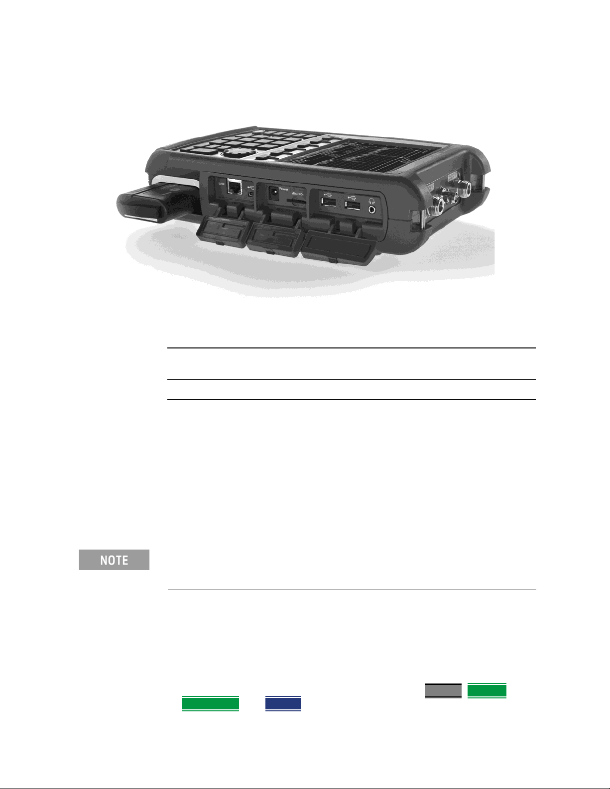
1. Open the battery door Push the button on the battery compartment door while sliding the
2. Insert the battery. The terminals end of the battery is inserted into the compartment.
3. Close the battery door. Slide the battery compartment door upwards until it latches.
Battery Usage
When you receive your FieldFox, the lithium-ion battery is not installed, and it
is partially charged to approximately 40% to preserve battery life. A lithium-ion
battery has no memory effect, so it can be used partially charged, as shipped.
A fully charged battery will power your FieldFox for about four hours, so if you
plan to use it for this long, you should fully charge the battery.
The FieldFox will shut down to prevent the battery from discharging to a
level that is damaging. If this occurs, charge the battery either internally or
externally.
Learn more about the lithium-ion battery in Chapter 20, “Working with the
Lithium-Ion Battery”.
door outward.
Battery charge status is viewable:
— In the upper-right corner of the screen.
— On the Battery screen. To access the screen, select System
Diagnostics, and Battery.
2- 2 Keysight N9912-90001 User’s Guide
, Service
Page 23
Preparing for Initial Use of Your New FieldFox
FieldFox ON/OFF Settings
— On the battery. Open the FieldFox battery compartment door to view the
battery LCD.
To conserve battery power:
—Use Run/Hold to single-trigger a measurement when needed. Hold is
shown on the display.
—Press System
rotary knob, or numeric keypad to adjust the brightness to dim the FieldFox
display as much as possible.
— Briefly press the power button to switch to Standby mode when the
FieldFox is not being used.
preserved.
When powered by the battery only, the FieldFox can stay in Standby mode
for a maximum of four hours and then it powers off automatically. When
the relative battery charge drops by about 20%, the FieldFox will power off
to preserve the remaining charge.
then Display then Brightness. Use the arrows, the
Press again to restore power. All current settings are
To recharge a battery:
Use ONLY a FieldFox charger to recharge a battery.
— The battery can be fully charged while in the FieldFox in about 4 hours with
the FieldFox either ON or OFF.
— The battery can be fully charged externally using the external battery
charger (Opt 872) in about 4 hours.
— When the battery is removed, the FieldFox can still be powered by the
AC/DC adapter.
FieldFox ON/OFF Settings
The FieldFox power button shut down/standby sequence includes a 10
second counter that allows you to either choose a softkey to immediately
initiate the action
counter expire after 10 seconds then perform the action.
*Restart can only be enabled via the Restart
—To turn power ON, briefly press the power button. Boot-up takes about 1
minute.
—To switch to Stand by mode (low battery drain), briefly press the power
button. See the Note above concerning Stand By.
Keysight N9912-90001 User’s Guide 2- 3
(Stand by / Shut down / Restart*), or to let the countdown
softkey.
Page 24
2-
Preparing for Initial Use of Your New FieldFox
FieldFox High Temperature Protection
— To turn Power OFF (very low battery drain), press and hold the power
button. Data and instrument state are NOT automatically saved when the
FieldFox is powered OFF. Learn how to save data and instrument state in
Chapter 17, “File Management”, on page 17-1. See the Note above
concerning Shut down.
— To restart FieldFox, press the power button and press Restart
above concerning Restart.
—Press Cancel
to exit the power down sequence.
— You can also access the power down softkey menu choices (Standby
down, Restart, and Cancel) by using the Mode hardkey:
—Press Mode
—Then More
.
.
—Then Shut down
— You can make a setting to automatically Power ON the FieldFox when a
power source is connected. Learn how on
Power Button LED Status
Solid green Power is ON
Blinking green FieldFox in Stand By mode
Blinking amber Battery charging
Blinking amber and green Stand By mode and battery charging
. See the Note
, Shut
.
“Power ON” on page 18-19.
Not lit Power is Off and battery is not charging
FieldFox High Temperature Protection
The following features prevent degradation or damage in the event of high
internal temperatures in the FieldFox.
Do NOT store the FieldFox in the soft-case while powered ON or in
Standby mode.
How to monitor the internal FieldFox temperature:
—Press System, then Service Diagnostics.
—Then Internal Temperatures
.
2- 4 Keysight N9912-90001 User’s Guide
Page 25
Preparing for Initial Use of Your New FieldFox
Avoid Overpowering the FieldFox
— The temperature at which the following events occur is the average of the
RF1, RF2, SB1, SB2 temperatures. These temperatures come from internal
sensors embedded within FieldFox.
Temperature Control Mode
At approximately 73°C, the FieldFox enters Temperature Control mode by
reducing display intensity and measurement speed. This should decrease the
internal temperature which preserves measurement accuracy and maintains
the long-term reliability of the FieldFox.
When entering Temperature Control mode, save your instrument state and
data that you want to keep.
When the temperature drops to approximately 71°C, normal operating settings
are restored.
Measurement speed specifications do NOT apply in Temperature Control
Mode.
High-Temp Shut down
In extreme situations, Temperature Control mode may not stop an increase in
the FieldFox internal temperature. At approximately 75°C, High-Temperature
Shut down will engage and turn OFF the FieldFox.
Just prior to shut down, the FieldFox will display a warning of imminent shut
down.
Avoid Overpowering the FieldFox
The FieldFox can be damaged with too much power or voltage applied.
Exceeding the maximum RF power levels shown below will cause an ADC Over
Range message to appear on the screen.
Maximum Input Voltages and Power:
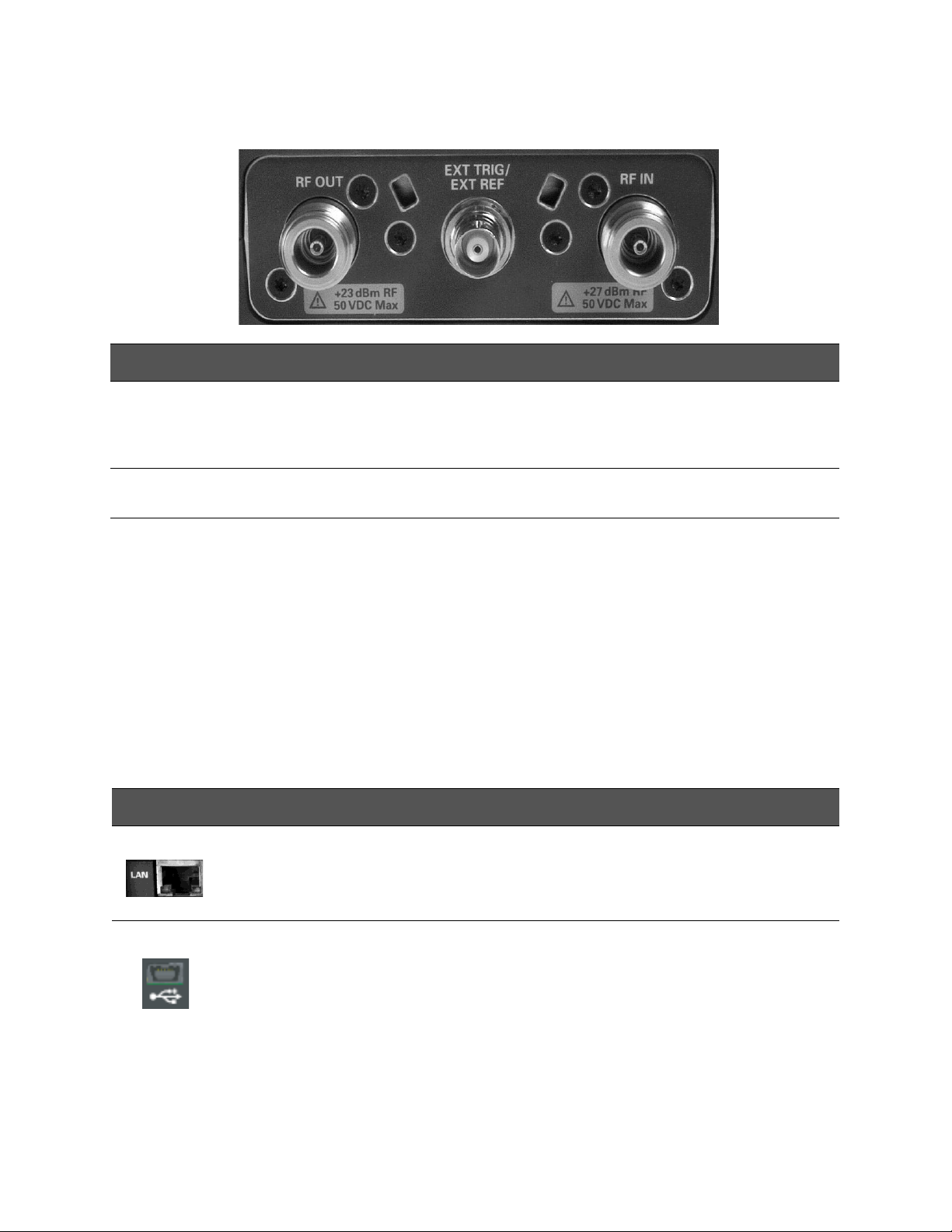
— RF OUT Connectors: ±50 VDC, +23 dBm RF
— RF IN: ±50 VDC, +27 dBm RF
— DC Input: 19 VDC, 4 ADC
— Learn more about Maximum power and voltages in the FieldFox Data
Sheet on page B-3
.
Keysight N9912-90001 User’s Guide 2- 5
Page 26

2-
Preparing for Initial Use of Your New FieldFox
Avoid Overpowering the FieldFox
Very often, coaxial cables and antennas build up a static charge, which, if
allowed to discharge by connecting to the FieldFox, may damage the
instrument input circuitry. To avoid such damage, it is recommended to
dissipate any static charges by temporarily attaching a short to the cable
or antenna prior to attaching to the FieldFox.
2- 6 Keysight N9912-90001 User’s Guide
Page 27
Preparing for Initial Use of Your New FieldFox
Take the FieldFox Tour
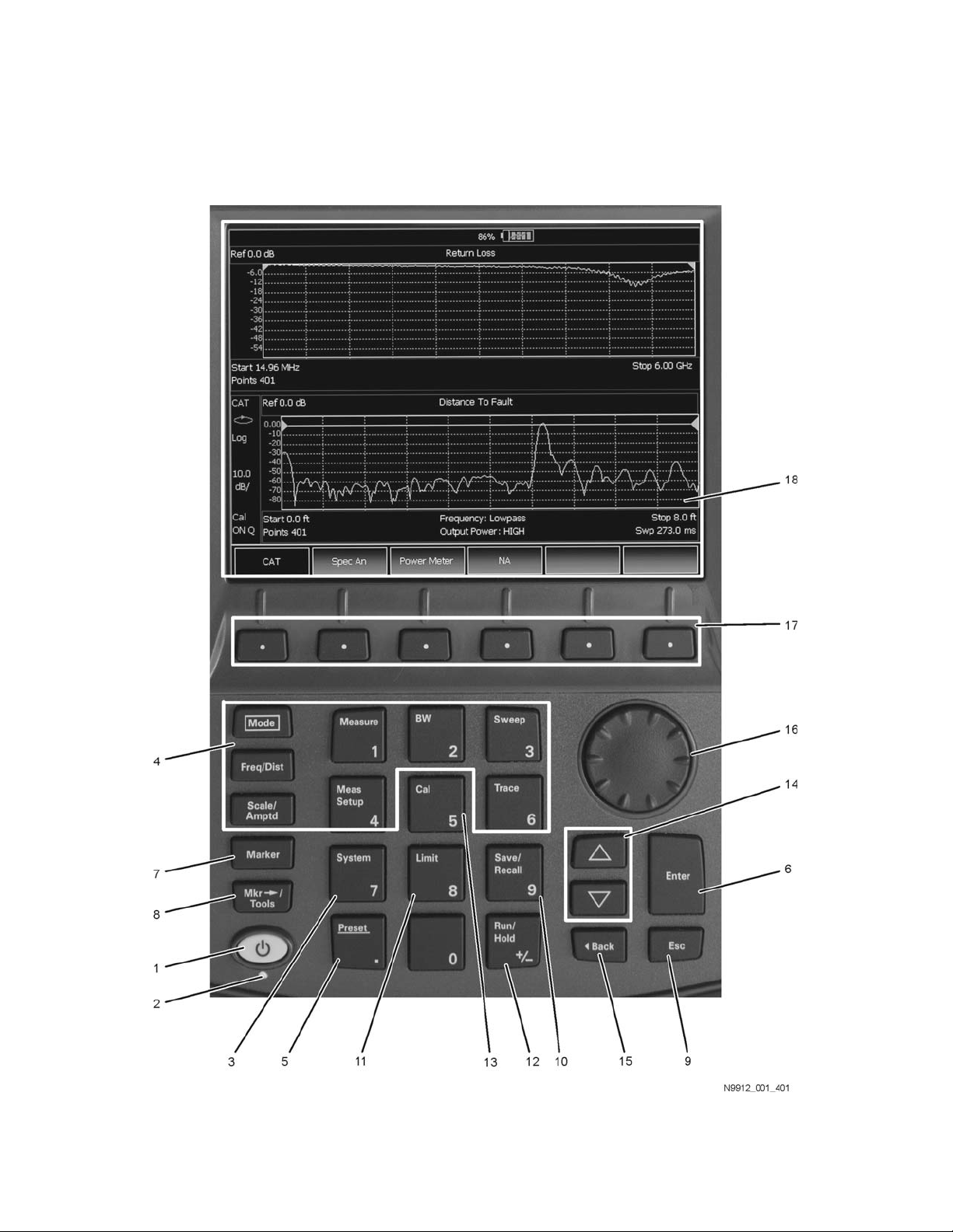
Take the FieldFox Tour
Front Panel
Keysight N9912-90001 User’s Guide 2- 7
Page 28
2-
Preparing for Initial Use of Your New FieldFox
Take the FieldFox Tour
No. Caption Description Learn
More:
1 Power ON: press momentarily.
STAND BY: with FieldFox power ON, press briefly.
OFF: press and hold until the FieldFox shuts off (about 4 seconds).
2 LED Not lit: FieldFox OFF, not charging
Green: FieldFox ON. Charging status indicated by battery icon on screen
Orange, flashing: FieldFox STAND BY
Orange, intensity increasing, flashing slowly: FieldFox OFF, charging
3
System
4 Function keys
Displays a sub-menu for system setup Chapter
Includes: Freq/Dist, Scale/Amptd, BW, Sweep, Trace, Meas
Setup, Measure, and Mode.
5
Preset
Returns the analyzer to a known state “How to
“FieldFox
ON/OFF
Settings”
on page
2-3
“Power
Button
LED
Status”
on page
2-4
18,
“System
Settings”,
on
page 181
Refer to
specific
Mode.
Preset the
FieldFox”
on page
18-3
6
Enter
7
Marker
8
Mkr-->Tools
9
Esc
10
Save/Recall
2- 8 Keysight N9912-90001 User’s Guide
Confirms a parameter selection or configuration --
Activates marker function “All about
Markers”
on page
16-2
Displays a sub-menu for marker functions “All about
Markers”
on page
16-2
Exits and closes the dialog box or clears the character input --
Saves the current trace or recalls saved data from memory “Saving
and
Recalling
Files” on
page
17-2
Page 29
Preparing for Initial Use of Your New FieldFox
Take the FieldFox Tour
No. Caption Description Learn
More:
11
Limit
12
Run/Hold
13
Cal
14 Arrow keys Increases or decreases a value or setting. --
15 Returns to the previous menu selection. --
16 Rotary knob Highlights an item for selection, or enables incremental changes to values. --
17 Softkeys Allows selection of settings for configuring and performing measurements, and
Sets limit lines for quick Pass/Fail judgment “All about
Toggles between free Run and Hold/Single operation. “Run/Hol
Displays a sub-menu for calibration functions “Calibrati
for other FieldFox functions.
Limit
Lines” on
page
16-14
d” on
page
18-2
on
Method
Summary
” on page
7-11
--
18 Screen Transflective screen, viewable under all lighting conditions. If you are using your
FieldFox in direct sunlight, you do not need to shield the display from the
sunlight. In bright lighting conditions, the display is brighter and easier to read
when you allow light to fall directly on the screen. Alternative color modes exist
that maximize viewing in direct sunlight conditions, as well as other conditions
such as nighttime work.
Clean the Transflective screen with gentle and minimal
wiping using Isopropyl alcohol applied to a lint-free cloth.
“Screen
Tour” on
page
2-12
Keysight N9912-90001 User’s Guide 2- 9
Page 30
2-
Preparing for Initial Use of Your New FieldFox
Take the FieldFox Tour
Top Panel
Caption Descriptions Learn More:
RF Output For CAT and NA measurements, use to make reflection measurements.
Maximum: ±50 VDC, +23 dBm RF
Ext Trig/Ext
Ref
RF In For CAT and NA mode, use to make transmission measurements.
External Reference connector to connect to an external frequecny reference.
Maximum: 5.5 VDC.
For SA use to make all measurements.
Maximum: ±50 VDC, +27 dBm RF.
“CAT Mode Settings”
on page 3-3
“NA Mode Settings” on
page 5-3
“SA Mode Settings” on
page 8-4
“Frequency Reference
Source” on page 18-15
“Triggering” on page
8-25
Side Panel
Connector Description Learn More
Ethernet cable connector to read trace data using the FieldFox Data Link
Software and connect to the FieldFox remotely.
Download the latest version of the software at:
www.keysight.com/find/fieldfoxsupport
On the N9912A units with serial number prefixes ≥5607, the mini-USB port
can be connected to your PC’s standard USB port to send SCPI commands.
Chapter 19, “Using
the Mini-USB Port
to send SCPI
Commands and
Queries (N9912A
units with serial
number prefixes
≥5607 Only)”, on
page 19-1
2- 10 Keysight N9912-90001 User’s Guide
Page 31
Preparing for Initial Use of Your New FieldFox
Take the FieldFox Tour
Connector Description Learn More
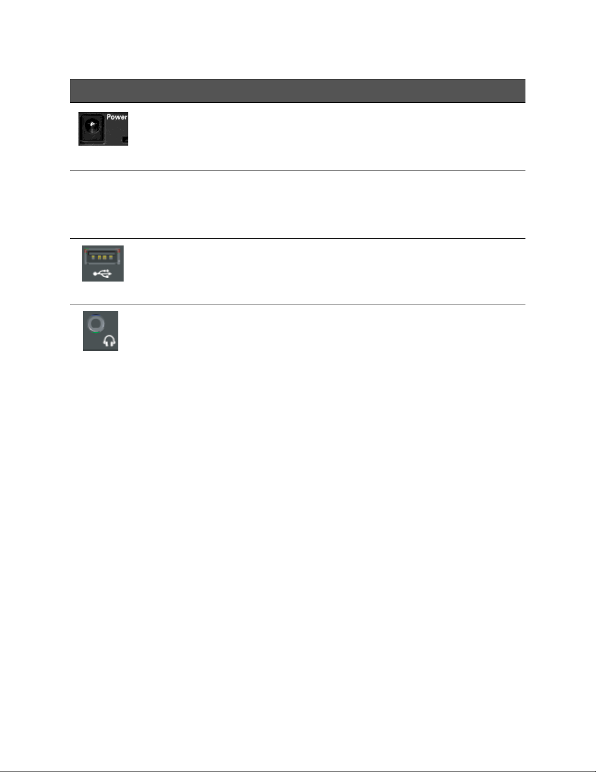
DC power connector used to connect to the AC/DC adapter. Maximum: 19
VDC, 4 ADC.
Micro Secure Digital slot. Use to extend the memory of the FieldFox. “Saving and
Standard USB connector used to connect a power sensor for Power Meter
Mode. Also used to save files to a USB flash drive. Use of Keyboard and
Mouse is NOT supported.
Audio output jack for use with SA Mode Tune and Listen. “Saving and
“Triggering” on page
8-25
Recalling Files” on
page 17-2
--
Recalling Files” on
page 17-2
Keysight N9912-90001 User’s Guide 2- 11
Page 32
2-
Preparing for Initial Use of Your New FieldFox
Take the FieldFox Tour
Screen Tour
Caption Description Learn More:
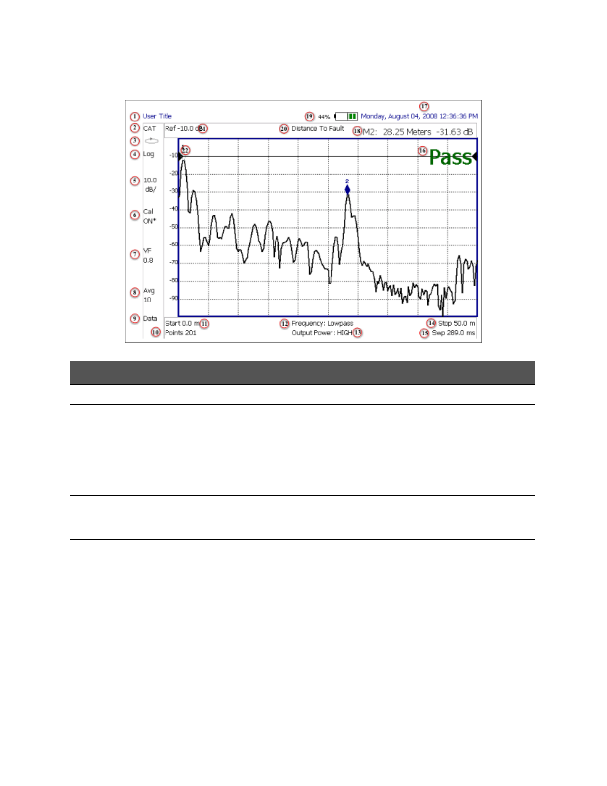
1 Title – write your own text here “Title” on page 18-6
2 Current Mode --
3 Run / Hold “Run/Hold” on page
18-2
4 Display Format Mode dependent
5 Scale/division Mode dependent
6 Calibration Status (CAT and NA)
Detection Method (SA)
“Cal ON ? –
Questionable
Accuracy” on page 7-8
7 Velocity Factor (Fault Meas) “About Velocity Factor
and Cable Loss” on
page 4-22
8 Averaging Status and Count Mode dependent
9 Data / Mem Display (CAT and NA)
Step / FFT (SA)
“All about Limit Lines”
on page 16-14
“Resolution Band wid th
(Res BW)” on page
8-20
10 Resolution Setting Mode dependent
11 Measurement Start Freq or Distance Mode dependent
2- 12 Keysight N9912-90001 User’s Guide
Page 33

Preparing for Initial Use of Your New FieldFox
Take the FieldFox Tour
Caption Description Learn More:
12 Bandpass / Lowpass setting (Fault Meas)
IF BW in NA Mode
13 Output Power Level (CAT and NA) “Output Power” on
14 Measurement Stop Freq or Distance Mode dependent
15 Actual Sweep Time Mode dependent
16 Limit Line Status “All about Limit Lines”
17 Time and Date “Date and Time,
18 Marker Readout “All about Markers” on
19 Battery Status “Viewing the Battery
20 Measurement Type (CAT and NA) --
21 Reference Level Mode dependent
“DTF Measurement
Settings” on page 4-19
page 3-9
on page 16-14
Format, and Time Zone
Settings” on page
18-16
page 16-2
Charge Status” on
page 20-1
22 Reference Position Mode dependent
Keysight N9912-90001 User’s Guide 2- 13
Page 34
2-
Preparing for Initial Use of Your New FieldFox
How to Enter Numeric Values
How to Enter Numeric Values
Many settings on the FieldFox require the entry of numeric values.
How to enter numeric values
Use any combination of the following keys:
— Numeric 0–9 keys, along with the polarity (+/-
— Up/Down arrow keys to increment or decrement values.
— Rotary knob to scroll through a set of values.
— Back
— Esc
erases previously entered values.
exits data entry without accepting the new value.
To complete the setting, press Enter
Multiplier Abbreviations
Many times after entering numeric values, a set of multiplier or suffix softkeys
are presented. The following explains the meaning of these abbreviations.
Select Frequency multipliers as follows:
— GHz Gigahertz (1e9 Hertz)
— MHz
— KHz
— Hz
Megahertz (1e6 Hertz)
Kilohertz (1e3 Hertz)
Hertz
) key.
or a different softkey or hardkey.
Select Time multipliers as follows:
— s Seconds
— ms
milliseconds (1e–3)
microseconds (1e–6)
— us
nanoseconds (1e–9)
— ns
— ps
picoseconds (1e-12)
2- 14 Keysight N9912-90001 User’s Guide
Page 35

Preparing for Initial Use of Your New FieldFox
Connector Care
Connector Care
— Never store connectors, airlines, or calibration standards loose in a box. This
— Install protective end caps when connectors are not in use.
— Keep connector temperature the same as the test instrument. Holding the
— Do not touch the mating plane surfaces. Natural skin oils and microscopic
— Do not set connectors contact-end down on a hard surface. The plating and
— Wear a grounded wrist strap and work on a grounded, conductive table
is a common cause of connector damage.
connector in your hand or cleaning connector with compressed air can
significantly change the temperature. Wait for connector temperature to
stabilize before using in calibration or measurements.
particles of dirt are difficult to remove from these surfaces.
mating plane surfaces can be damaged if the interface comes in contact
with any hard surface.
mat. This helps protect the analyzer and devices from electrostatic
discharge (ESD).
—Refer to “Connector Care Review” on page A-1.
Because of the very small and precise mechanical tolerances of mmWave
connectors, minor defects, damage, and dirt can significantly degrade
repeatability and accuracy. In addition, a dirty or damaged connector can
destroy connectors that are mated to it. For this reason, NEVER use a
damaged connector. See also
http://na.support.keysight.com/pna/connectorcare/Connector_Care.htm
Keysight N9912-90001 User’s Guide 2- 15
Page 36

2-
Preparing for Initial Use of Your New FieldFox
Connector Care
2- 16 Keysight N9912-90001 User’s Guide
Page 37
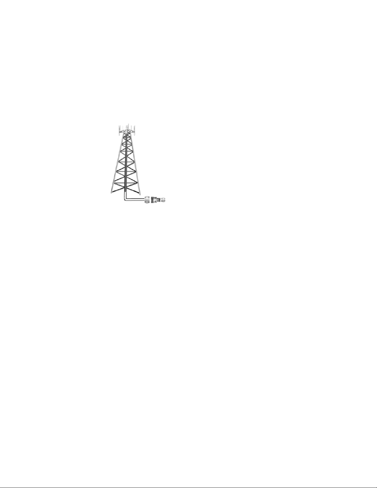
Keysight Handheld Analyzers
N9912A User’s Guide
3 CAT (Cable and Antenna Test) Mode
CAT Mode is typically used to test an entire transmission system,
from the transmitter to the antenna. This process is sometimes
referred to as Line Sweeping.
CAT Mode is similar to NA (Network Analyzer) Mode. Learn more in
the Supplemental Online Help:
http://na.support.keysight.com/fieldfox/help/SupHelp/F
ieldFox.htm
CAT Mode Distance to Fault measurements are discussed in
Chapter 4, “DTF (Distance to Fault) Measurements.”.
In this Chapter
“Measurement Selection” on page 3-3
“Quick Settings Table” on page 3-4
“Frequency Range” on page 3-5
“Scale Settings” on page 3-5
“Averaging” on page 3-6
“Smoothing” on page 3-7
“Single or Continuous Measure” on page 3-7
“Resolution (Number of Data Points)” on page 3-8
“Sweep Time” on page 3-8
“Output Power” on page 3-9
“Interference Rejection” on page 3-10
“Coupled Frequency” on page 3-11
3- 1
Page 38

3-
CAT (Cable and Antenna Test) Mode
Procedures
“Return Loss Measurements” on page 3-12
“1-Port Cable Loss Measurements” on page 3-12
“2-Port Insertion Loss Measurements” on page 3-14
“DTF (Distance to Fault) Measurements” on page 4-17
See Also
“Calibration for NA, CAT, and VVM Modes” on page 7-1
“All about Markers” on page 16-2
“All about Limit Lines” on page 16-14
“All about Trace Math” on page 16-19
Making 75Ω (ohm) Measurements at the FieldFox Supplemental Online Help:
http://na.support.keysight.com/fieldfox/help/SupHelp/FieldFox.htm
3- 2 Keysight N9912-90001 User’s Guide
Page 39
CAT (Cable and Antenna Test) Mode
CAT Mode Settings
CAT Mode Settings
Select CAT Mode before making any setting in this chapter.
How to select CAT Mode
—Press Mode.
—Then CAT.
Measurement Selection
How to select a CAT Mode Measurement
Learn more about the following measurements in the Supplemental Online
Help: http://na.support.keysight.com/fieldfox/help/SupHelp/FieldFox.htm
Press Measure 1
Then choose one of the following: These softkeys also appear after CAT Mode
is selected.
— Distance To Fault
Transform (IFT) calculations to determine and display the distance to, and
relative size of, a fault or disruption in the transmission line. Units are in
return loss format, expressed as a positive number in dB, unless the
measurement selected is DTF (VSWR). Learn more about DTF
Measurements refer to Chapter 4, “DTF (Distance to Fault)
Measurements.”.
— Return Loss & DTF
measurement. Use this format to display the frequency settings that are
used to make the DTF measurement. The frequency range settings for these
two measurements can be coupled or uncoupled. Learn more on
page 3-11.
Calibrations are applied to both traces
When in Hold mode and Single sweep is performed, only the active
trace is triggered. Use the arrows to activate a trace
— Return Loss
incident signal energy MINUS the amount of energy that is reflected. The
higher the trace is on the screen, the more energy being reflected back to
the FieldFox. Learn how to measure Return Loss in “Return Loss
Measurements” on page 3-12.
.
1-port reflection measurement that uses Inverse Fourier
Displays both a Return Loss measurement and a DTF
1-port reflection measurement that displays the amount of
— VSWR
reflection measurement that displays the ratio of the maximum reflected
voltage over the minimum reflected voltage. The higher the trace is on the
screen, the more energy being reflected back to the FieldFox.
— DTF (VSWR)
Keysight N9912-90001 User’s Guide 3- 3
(Voltage Standing Wave Ratio – also known as SWR) 1-port
Distance to Fault in VSWR format.
Page 40
3-
CAT (Cable and Antenna Test) Mode
CAT Mode Settings
— Cable Loss (1-Port) 1-port reflection measurement that displays the loss of
a transmission line. Learn more on page 3-12.
— Insertion Loss (2-Port)
measurement that accurately displays the loss through a cable or other
device in dB. Both ends of the cable must be connected to the FieldFox. NO
phase information is included in this measurement. Learn more at “2-Port
Insertion Loss Measurements” on page 3-14.
— DTF (Lin)
Distance to Fault in Linear format.
— TDR (Lin rho)
without reflections shows as 0 (zero). Maximum reflections from an open or
short show as 1.
— TDR (ohm)
— TDR & DTF
The Y-axis of the display is impedance (ohms).
TDR and DTF are displayed.
Quick Settings Table
Both CAT and NA Modes allow you to view and change most relevant settings
from a single location. All of these settings are discussed in this chapter and,
unless otherwise noted, ALL of these settings can also be made using the
standard softkey menus.
How to view and change Quick Settings
(Option 110 ONLY) 2-port transmission
The Y-axis of the display is linear, real, unitless values. A trace
—Press Meas Setup 4.
—Then Settings
—Press Next Page
.
and Previous Page to view all settings. If these softkeys
are NOT available, then all available settings fit on one page.
—To change a setting:
— Use the arrows to highlight a setting.
—Then press Edit
. The current setting changes to yellow.
— Some settings require you to press a softkey to change the value.
Otherwise, use the numeric keypad, arrows, or rotary knob to
change the value.
— When finished changing a value, press Done Edit
—Press Dock Window
to relocate the Settings table to a position relative to
.
the trace window. The Dock Window setting persists through a Preset.
Choose from the following
— Full (Default setting) Only the Settings table is shown on the screen.
The trace window is temporarily not shown
— Left The Settings table is shown to the left of the trace window
3- 4 Keysight N9912-90001 User’s Guide
Page 41
CAT (Cable and Antenna Test) Mode
CAT Mode Settings
— Bottom The Settings table is shown below the trace window
— When finished changing ALL settings, press Done
Frequency Range
Set the range of frequencies over which you would like to make CAT Mode
measurements.
When the frequency range is changed after a calibration is performed, the cal
becomes interpolated. Learn more in “Interpolation” on page 7-7.
How to set Frequency Range
—Press Freq/Dist.
— Then choose from the following
— Start
— Center
frequencies (half on either side of center).
— Follow each setting by entering a value using the numeric keypad,
arrows, or the rotary knob.
— After using the keypad, select a multiplier key. Learn about multiplier
abbreviations in Chapter 2, “Multiplier Abbreviations.”
to save your settings
and Stop frequencies - beginning and end of the sweep.
and Span frequencies – the center frequency and span of
— After using the arrows or the rotary knob, press Enter
Scale Settings
Adjust the Y-axis scale to see the relevant portions of the data trace. The Y-axis
is divided into 10 graticules.
This setting can be changed at any time without affecting calibration accuracy.
How to set Scale
—Press Scale / Amptd.
— Then choose from the following three methods:
1. Autoscale
2. Autoscale All
3. Set Scale, Reference Level, and Reference Position:
. The
amount of frequency increment is based on the current span and can
NOT be changed in CAT Mode.
Automatically adjusts the Y-axis to comfortably fit the Min
and Max amplitude of the trace on the screen.
Autoscales all of the traces on the screen, useful only
for dual-trace configurations.
Keysight N9912-90001 User’s Guide 3- 5
Page 42
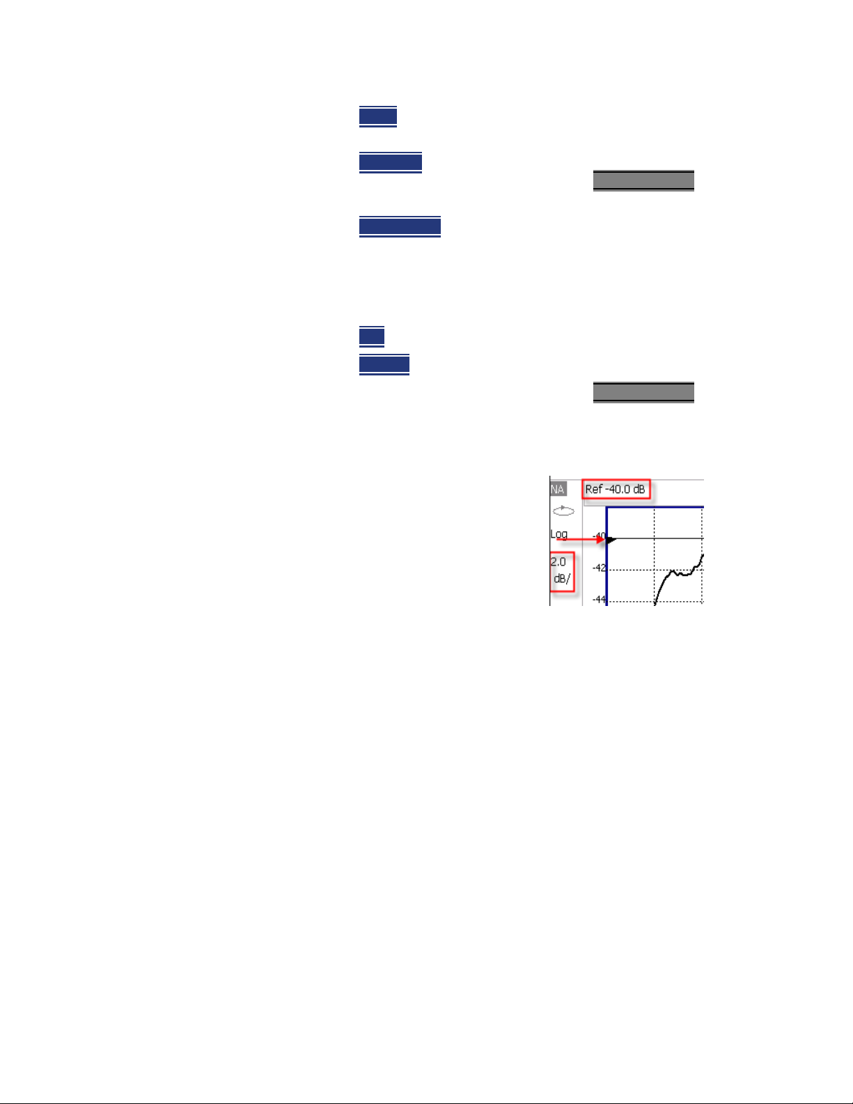
3-
CAT (Cable and Antenna Test) Mode
CAT Mode Settings
— Scale Manually enter a scale per d ivision to view specific
areas of the trace.
— Ref Level
Manually set the value of the reference line.
Enter a negative value by pressing Run/Hold (+/-)
before or after typing a value.
— Ref Position
Manually set the position of the reference
line. Values must be between 0 (TOP line) and 10
(BOTTOM line).
4. Set Top and Bottom graticule values. The scale per division is
calculated.
— Top
— Bottom
to set the value of the Top graticule.
to set the value of the Bottom graticule.
— Enter a negative value by pressing Run/Hold (+/-)
before or after typing a value.
Scale annotation on the FieldFox screen
Reference Line = red arrow
Ref Level = -40 dB
Ref Position = 1
either
either
Averaging
Trace Averaging helps to smooth a trace to reduce the effects of random noise
on a measurement. The FieldFox computes each data point based on the
average of the same data point over several consecutive sweeps.
Average Count determines the number of sweeps to average; the higher the
average count, the greater the amount of noise reduction.
An average counter is shown in the left edge of the screen as Avg N. This
shows the number of previous sweeps that have been averaged together to
form the current trace. When the counter reaches the specified count, then a
‘running average’ of the last N sweeps is displayed. Average Count = 1 means
there is NO averaging.
Scale = 2 dB per division
3- 6 Keysight N9912-90001 User’s Guide
Page 43
CAT (Cable and Antenna Test) Mode
CAT Mode Settings
This setting can be changed at any time without affecting calibration accuracy.
Averaging is often used to increase the dynamic range of a measurement.
To achieve the highest dynamic range, select NA mode and reduce the IF
Bandwidth setting. Learn more about dynamic range in
Range” on page 5-20
.
“Increase Dynamic
How to set Trace Averaging
—Press BW 2.
—Then Average N
— Enter a value using the numeric keypad. Enter 1 for NO averaging.
—Press Enter
— While Trace Averaging is in process, press Sweep 3
Smoothing
Trace smoothing averages a number of adjacent data points to smooth the
peak-to-peak noise values on a displayed trace. The number of adjacent data
points that are averaged is known as the smoothing aperture. Aperture is set
by specifying a percentage of the X-axis span.
Trace smoothing does NOT significantly increase measurement time.
Smoothing can be used with any CAT format.
When enabled, Smo appears on the FieldFox screen.
How to set Smoothing
—Press BW 2
—Then Smoothing ON OFF
where N is the current count setting.
.
then Restart to restart
the averaging at 1.
.
.
—Then Sm. Aperture
numeric keypad.
—Press Enter
.
and enter a value between 0 and 25 (percent) using the
Single or Continuous Measure
This setting determines whether the FieldFox sweeps continuously or only once
each time the Single
or to allow you to save or analyze a specific measurement trace.
This setting can be changed at any time without affecting calibration accuracy.
How to set Single or Continuous
—Press Sweep 3.
Keysight N9912-90001 User’s Guide 3- 7
button is pressed. Use Single to conserve battery power
Page 44
3-
CAT (Cable and Antenna Test) Mode
CAT Mode Settings
— Then choose one of the following:
— Single
Automatically sets Continuous OFF and causes FieldFox to
make ONE sweep, then hold for the next Single key press. Hold is
annotated in the upper left corner of the display when NOT sweeping,
and changes to an arrow --> while the sweep occurs
— Continuous
Makes continuous sweeps. This is the typical setting
when battery power is not critical.
You can also use Run / Hold +/-
Resolution (Number of Data Points)
Data points are individual measurements that are made and plotted across the
X-axis to form a trace. Select more data points to increase measurement
resolution. However, more data points require more time to complete an entire
measurement sweep
When the Resolution is changed after a calibration is performed, the cal
becomes interpolated. Learn more in “Interpolation” on page 7-7.
How to set Resolution
—Press Sweep 3.
—Then Resolution
.
to toggle between Single and Continuous.
— Then choose one of the following:
101 | 201 | 401 | 601 | 801 | 1001 |1601 | 4001 | 10001
— Using SCPI, Resolution can be set to any number of points between 3 and
10001. See the Programming Guide at
http://na.support.keysight.com/fieldfox/help/
Sweep Time
The fastest possible sweep time is always used as the default setting. Use the
Min Swp Time setting to slow the sweep time when measuring long lengths of
cable.
Learn more in the FieldFox Supplemental Help at:
http://na.support.keysight.com/fieldfox/help/SupHelp/FieldFox.htm
The actual sweep time is shown on the FieldFox screen. See “Take the FieldFox
Tour” on page 2-7. To increase the sweep time, enter a value that is higher
than the actual sweep time. The increase will not be exactly the amount that
you enter, as the actual sweep time is the composite of many factors.
Measurement speed specifications do NOT apply in Temperature Control
Mode. Learn more in “FieldFox High Temperature Protection” on page 2-4
.
.
3- 8 Keysight N9912-90001 User’s Guide
Page 45
CAT (Cable and Antenna Test) Mode
CAT Mode Settings
How to set Sweep Time
—Press Sweep 3.
—Then Min Swp Time
— Enter a value using the numeric keypad.
— Press a multiplier key. Learn more in “Multiplier Abbreviations” on
page 2-14.
Output Power
Set the power level out of the FieldFox to High, Low, or manually set power
level to a value between High and Low.
Generally, the high power setting is used when measuring passive, high-loss
devices to place the signal farther from the noise floor. However, for devices
that are sensitive to high power levels such as amplifiers, use the Low power
setting.
For best measurement accuracy, use the Manual power setting at -15 dBm.
After calibration, the power level can be decreased for amplifiers, or increased
for higher dynamic range.
Power Level settings in this mode will NOT change Power Level settings in
other modes. To help prevent damage to your DUT, use caution when
changing modes with your DUT connected to the FieldFox test ports.
.
How to set Output Power
—Press Meas Setup 4.
—Then Power
—Then Output Power
— High (Default setting) Sets output power to the maximum achievable
— Low Sets output power to approximately –27 dBm,
— Man Set output power to an arbitrary value,
—Then press Nominal Power
— Then enter a value using the numeric keypad, the arrows, or the
.
.
power at all displayed frequencies. Please see “Specifications/Data
Sheet” on page B-3 for expected power levels.
.
rotary knob.
Keysight N9912-90001 User’s Guide 3- 9
Page 46
3-
CAT (Cable and Antenna Test) Mode
CAT Mode Settings
—Press Enter.
Nominal here means: a general, descriptive term or design parameter. It is
not tested and not covered by the product warranty.
In FieldFox’s with FW <A.08.15, the Nominal Output displayed on the
bottom right side of the display indicates a range of low and high power
values. Your actual measured output power could be a little lower or a
little higher. Refer to Figure 3-1.
If you have the USB power sensor feature (Option 302) you can measure
the actual output power for your measurement. Refer to page Chapter 11,
“Power Meter Mode (Option 302).”
Figure 3-1 Nominal Output Power
Interference Rejection
Use this setting when you suspect that other signals in the area are interfering
with a measurement. Interference may look like a spike or lack of stability in the
measurement trace. While monitoring a measurement at a specific frequency,
toggle this setting between ON and OFF. If the measurement result decreases
while ON, then there is an interfering signal in the area. Continue to make
measurements with Interference Rejection ON. However, this will slow the
measurement speed.
Once enabled, up to SIX sweeps may be required before the interfering signal
is neutralized.
This setting can be changed at any time without affecting calibration accuracy.
How to set Interference Rejection
—Press Meas Setup 4.
—Then Interference Rejection [current setting]
— Then choose from the following:
No interference rejection and fastest possible sweep speed
— Off
— Minimum
.
The lowest level of Interference rejection.
— Medium
3- 10 Keysight N9912-90001 User’s Guide
The medium level of Interference rejection.
Page 47
CAT (Cable and Antenna Test) Mode
CAT Mode Settings
— Maximum The highest level of Interference rejection.
Coupled Frequency
This setting, especially useful for a Return Loss & DTF measurement, allows
both measurements to have different frequency ranges.
How to set Coupled Frequency
With a Return Loss & DTF measurement present:
—Press Meas Setup 4
— Select the DTF measurement (Tr2) using the arrows.
— Then choose from the following:
— Coupled Freq ON
frequency range settings.
— Coupled Freq OFF
individual frequency range settings. When set to OFF:
— The Return Loss measurement frequency settings are made in the
usual manner. Learn how at “Frequency Range” on page 3-5. When
a new Start or Stop frequency is selected, Coupled Frequency is
automatically set to OFF.
— The DTF measurement is made using the frequencies as determined
by the DTF Frequency Mode setting. Learn more in “DTF
Measurement Settings” on page 4-19.
.
- Both the Return Loss and DTF traces have the same
(default setting) - Both traces are allowed to have
Keysight N9912-90001 User’s Guide 3- 11
Page 48
3-
CAT (Cable and Antenna Test) Mode
Return Loss Measurements
Return Loss Measurements
Return loss can be thought of as the absolute value of the reflected power
compared to the incident power.
When measuring an OPEN or SHORT, all incident power is reflected and
approximately 0 dB return loss is displayed.
When measuring a LOAD, very little power is reflected and values of 40 dB to
60 dB are displayed.
The minus sign is usually ignored when conveying return loss. For example, a
component is said to have 18 dB return loss, rather than –18 dB.
How to Measure Return Loss
— Connect the jumper cable or any adapter used to connect the device under
test (DUT).
— Select Preset
— Select Mode
—Then Return Loss
—Press Freq/Dist
measurement.
—Press Meas Setup 4
calibrating.
— Disconnect the jumper cable or DUT and press Cal 5
calibration prompts.
— Reconnect the jumper cable or DUT.
— The return loss trace is displayed on the FieldFox screen.
then Preset Returns the FieldFox to known settings
then CAT (Cable and Antenna Test)
(Default measurement).
and enter Start and Stop frequency values of the
then Settings to make appropriate settings before
1-Port Cable Loss Measurements
While all cables have inherent loss, weather and time will deteriorate cables
and cause even more energy to be absorbed by the cable. This makes less
power available to be transmitted.
then follow the
A deteriorated cable is not usually apparent in a Distance to Fault
measurement, where more obvious and dramatic problems are identified. A
Cable Loss measurement is necessary to measure the accumulated losses
throughout the length of the cable.
3- 12 Keysight N9912-90001 User’s Guide
Page 49
CAT (Cable and Antenna Test) Mode
1-Port Cable Loss Measurements
A 2-port Insertion Loss measurement is usually more accurate than a 1-port
Cable Loss measurement. However, to perform a 2-port Insertion Loss
measurement, both ends of the cable must be connected to the FieldFox, and
the FieldFox must have option 110 installed.
In high-loss conditions, a Cable Loss measurement becomes ‘noisy’ as the
test signal becomes indistinguishable in the FieldFox noise floor. This can
occur when measuring a very long cable and using relatively high
measurement frequencies. To help with this condition, use High Power
(
page 3-9) and Averaging (page 3-6).
How to make a 1-port Cable Loss Measurement
1. Press Preset then Preset..
2. Then More
then Cable Loss (1-Port).
3. Connect the cable to be tested.
4. Press Freq/Dist
and enter Start and Stop frequency values of the
measurement.
5. Press Sweep 3
then Min Swp Time. Increase the Sweep Time until a stable
trace is visible on the screen. The amount of time that is required increases
with longer cable lengths. Learn more in the Supplemental Online Help:
http://na.support.keysight.com/fieldfox/help/SupHelp/FieldFox.htm
6. Remove the cable to be tested.
7. Press Cal 5
, then QuickCal or OSL.
8. Follow the prompts to perform calibration at the end of the jumper cable
or adapter. Learn more about Calibration in Chapter 7, “Calibration for NA,
CAT, and VVM Modes”, on page 7-1.
9. Connect the cable to be tested.
Low-level standing waves (also known as ‘ripple’) which may be visible in
reflection measurements, can hide the actual loss of the cable. Steps 10
through 13 can minimize the ripple. Perform the measurement with and
without steps 10 through 13 and choose the method with the least amount
of ripple.
10.Connect a LOAD at the end of the cable to be tested. This limits the
reflections to faults that are located in the cable under test.
11.Press Trace 6
then Math and Memory then Data->Mem to store the trace
into Memory.
12.Remove the LOAD and leave the end of the cable to be tested open.
Keysight N9912-90001 User’s Guide 3- 13
Page 50
3-
CAT (Cable and Antenna Test) Mode
2-Port Insertion Loss Measurements
13.Press Data Math then Data – Mem. The ripple in the measurement is
removed. These minor imperfections in the cable should not be considered
in the Cable Loss measurement.
14.Use Averaging to remove random noise from high-loss measurements.
Press BW 2
then Average.
The displayed trace shows the Cable Loss values in one direction through the
cable. A Return Loss measurement would show the loss for both down the
cable and back. Therefore, a Cable Loss measurement is the same as a Return
Loss measurement divided by 2.
The average Cable Loss across the specified frequency range is shown on the
screen below the graticules.
2-Port Insertion Loss Measurements
A 2-port Insertion Loss measurement, available with option 110, is used to
measure the loss through a DUT (device under test) – or cable – over a
specified frequency range. The FieldFox signal source is transmitted out the RF
OUT connector, through the DUT, and into the RF IN connector. Both ends of
the DUT must be connected to the FieldFox, either directly or indirectly using
the cable used in the normalization cal.
‘Insertion’ loss simply means loss through a device, usually expressed in dB. It
is exactly the same measurement as “S21 Transmission” in NA Mode.
2-port Insertion Loss measurements are generally more accurate than 1-port
Cable Loss measurements.
A Normalization Cal is REQUIRED for making accurate 2-port CAT or NA
measurements. Learn “Normalize” on page 7-6
.
For highest accuracy, when measuring the DUT also attach any cable or
adapter that was used in the normalization cal.
How to make a 2-port Insertion Loss Measurement
—Press Mode
—Then More
then CAT.
then Insertion Loss (2-Port).
—Press Freq/Dist
and enter Start and Stop frequency values of the
measurement.
—Press Sweep 3
—Press Cal 5
, then select a Resolution setting.
, then press Normalization. Learn more in “Normalize” on
page 7-6.
— Connect the DUT and view the insertion loss measurement results.
3- 14 Keysight N9912-90001 User’s Guide
Page 51

CAT (Cable and Antenna Test) Mode
2-Port Insertion Loss Measurements
When measuring very long lengths of cable, it may be necessary to increase
the sweep time. Learn how on page 3-8. Learn why in the Supplemental
Online Help:
http://na.support.keysight.com/fieldfox/help/SupHelp/FieldFox.htm
Keysight N9912-90001 User’s Guide 3- 15
Page 52

3-
CAT (Cable and Antenna Test) Mode
2-Port Insertion Loss Measurements
3- 16 Keysight N9912-90001 User’s Guide
Page 53

Keysight Handheld Analyzers
N9912A User’s Guide
4 DTF (Distance to Fault) Measurements
CAT Mode Distance to Fault (DTF) measurements are generally used to locate
problems, or faults, in a length of cable or transmission line. In this chapter, the
cable to be tested is referred to as the DUT (Device Under Test).
Settings that are NOT unique to DTF measurements are documented in the
Chapter 3, “CAT (Cable and Antenna Test) Mode.”
In this Chapter
“How to make DTF Measurements” on page 4-18
“DTF Settings Table” on page 4-19
“DTF Measurement (Format)” on page 4-19
“DTF Start and Stop Distance” on page 4-20
“Frequency Mode” on page 4-20
“Coupled Frequency” on page 4-21
“Cable (Correction) Specifications” on page 4-22
“Window Settings” on page 4-25
“DTF Units” on page 4-25
“Calculated DTF values” on page 4-26
“About Alias Faults” on page 4-26
Optional settings
“All about Trace Math” on page 16-19
“All about Limit Lines” on page 16-14
“Saving and Recalling Files” on page 17-2
Trace Math is NOT available in DTF Measurements.
4- 17
Page 54
4-
DTF (Distance to Fault) Measurements
How to make DTF Measurements
How to make DTF Measurements
Before starting, you may need the following:
— Jumper cable or adapter to connect the beginning of the DUT to the
FieldFox.
— LOAD with correct connector type and gender to terminate the end of the
DUT (if possible).
— The known length and cable type of the DUT. If the cable type is not known,
then the Cable Loss (dB/Meter) and Velocity Factor of the DUT are required.
1. Connect any necessary jumper cable or adapter to the FieldFox RF OUT
port. Do NOT connect the DUT.
2. Press Preset
3. Then Mode
4. Then DTF
5. Press Freq/Dist
then Preset to return the FieldFox to the default settings.
then CAT.
.
, then Stop Distance and enter the length of the DUT. You
can optionally set the Start Distance
6. Press Cal 5
and follow the Cal prompts. Learn all about calibration in
Chapter 7.
7. Disconnect any components or antenna that should NOT be measured and
connect a LOAD at the end of the DUT.
8. Press Meas Setup 4
9. Either press Recall Coax Cable
then DTF Cable Specifications.
, or enter Velocity Factor and Cable Loss of
the DUT.
10. Connect the start end of the DUT to the FieldFox.
11. Press Meas Setup 4
then Settings then Next Page. If the Alias-free Range
setting is False, then you may see Alias faults on the screen. Learn more
on page 4-26.
4- 18 Keysight N9912-90001 User’s Guide
Page 55
DTF (Distance to Fault) Measurements
DTF Measurement Settings
DTF Measurement Settings
DTF Settings Table
You can set and view all of the DTF settings, including some calculated values,
on the DTF Settings table. Learn about the calculated values in “Calculated
DTF values” on page 4-26.
How to make settings on the DTF settings table
—Press Meas Setup 4.
—Then Settings
—Press Next Page
—To change a setting:
— Use the arrows or rotary knob to highlight a setting.
— Numeric settings can be changed by pressing numbers using the
numeric keypad. Then press Enter or select a suffix if available.
— Other settings require you to press Edit
change the value.
— When finished changing a value, press Done Edit
—Press Dock Window
the trace window. The Dock Window setting persists through a Preset.
Choose from the following:
— Full (Default setting) Only the Settings table is shown on the screen.
The trace window is temporarily not shown.
— Left The Settings table is shown to the left of the trace window.
— Bottom The Settings table is shown below the trace window.
.
and Previous Page to view all settings.
, then press a softkey to
.
to relocate the Settings table to a position relative to
— When finished changing ALL settings, press Done
to save your settings.
DTF Measurement (Format)
You can select from 3 different DTF Formats.
—Press Measure 1
— Then choose from:
— Distance to Fault (dB)
loss format, expressed as a positive number in dB.
— DTF (VSWR)
about SWR at the FieldFox Supplemental Online Help:
http://na.support.keysight.com/fieldfox/help/SupHelp/FieldFox.ht
m
Keysight N9912-90001 User’s Guide 4- 19
.
Faults are displayed on the Y-axis in return
Faults are displayed on the Y-axis in SWR. Learn more
Page 56
4-
DTF (Distance to Fault) Measurements
DTF Measurement Settings
— More then DTF (Lin) Faults are displayed on the Y-axis in linear
(unitless) format.
DTF Start and Stop Distance
In DTF measurements, you set the physical length of cable or other device to
be tested. The FieldFox calculates the frequency range of the measurement
from this distance. The longer the cable to be tested, the lower the frequencies
that are used. You can also set the frequencies manually using the Frequency
Mode [Bandpass] setting.
How to set Start and Stop Distance
— With a DTF measurement present, press Freq/Dist.
— Then choose from the following:
— Start Distance
— Stop Distance
Frequency Mode
All DTF measurements are made with frequency settings and, using Inverse
Fourier Transform (IFT), the time and distance to faults are calculated.
The start and stop frequencies for the measurement are always annotated
on the screen below the start and stop distances.
How to set Frequency Mode
With a DTF measurement present,
—Press Meas Setup 4
Enter a value using the numeric keypad, the
arrows, or the rotary knob, then Enter
. By default, the Start Distance
is set to 0 Meters. This means that the measurement will display
faults starting at the point at which calibration standards are
connected.
Enter a value between the start distance and 5 km (or
16,404 ft.) using the numeric keypad, the arrows, or the rotary
knob, then Enter
.
.
—Then Frequency Mode
.
— Choose one of the following:
— Lowpass Mode
The frequency range of a DTF measurement is set
automatically based on the Start and Stop Distances. Use Lowpass
mode when the DUT is a cable ONLY.
4- 20 Keysight N9912-90001 User’s Guide
Page 57
DTF (Distance to Fault) Measurements
DTF Measurement Settings
— Bandpass Mode (Default setting) The frequency range of a DTF
measurement is set manually. Use Bandpass mode when the DUT
contains a diplexer or other filtering device which does not pass
some frequencies.
Typically, you will set the frequency range of the measurement to the passband
of the filter. However, you may also want to test the ability of the filter to reject
unwanted frequencies. In this case, set the frequency range to include those
frequencies which the filter may not be adequately rejecting.
When the DTF frequencies are set manually, they may not be the optimum
frequencies for measuring the distance to fault. The distance may no longer be
alias-free. Learn more about alias-free range on page 4-26.
How to manually set Frequencies in Bandpass Mode
—Press Freq/Dist.
—Then Min Start Freq
measurement.
—Then Max Stop Freq
measurement.
—OR
—Press More
—Then Max Freq Span
measurement.
—Then Center Frequency
for the DTF measurement.
These settings specify the minimum and maximum frequencies to be used for
the DTF measurement. These exact frequencies may not be used, but a
narrower frequency range may be used that will still pass through the
bandpass filter.
To see the frequencies that are used in the DTF measurement, press Meas
Setup 4 then Settings then Next Page. The calculated Start and Stop
frequencies determine the exact frequency range being used.
Coupled Frequency
and type the start frequency to use for the DTF
and type the stop frequency to use for the DTF
.
and type the frequency range to use for the DTF
and type the center frequency of the range to use
When a Return Loss & DTF measurement is present, this setting allows you to
have different frequency ranges for each measurement. Learn more on
page 3-11.
Keysight N9912-90001 User’s Guide 4- 21
Page 58

4-
DTF (Distance to Fault) Measurements
DTF Measurement Settings
Cable (Correction) Specifications
By default, the FieldFox does NOT correct DTF measurements to account for
the inherent loss of a cable. However, to make more accurate DTF
measurements, the Cable Loss and Velocity Factor values should be
considered.
About Velocity Factor and Cable Loss
— Velocity Factor is a property of the physical material of a cable. A VF of 1.0
corresponds to the speed of light in a vacuum, or the fastest VF possible. A
polyethylene dielectric cable has VF = 0.66 and a cable with PTFE dielectric
has VF = 0.7.
— Cable Loss is specified in dB/meter. In addition to the length of the cable,
loss is also directly proportional to the frequency of the signal that passes
through the cable.
The following is an example showing how DTF cable correction works:
The DUT is a 100 meter transmission cable. The Cable Loss value is 1
dB/meter. This means that a signal traveling ONE WAY through the cable will
lose 10 dB of power (100 m * 1dB/m). Because the FieldFox performs this
measurement with 1 port, the test signal travels down the cable and then back,
for a total loss of 20 dB.
After a calibration has been performed, for the purpose of illustrating this
point, connect an OPEN to the end of the cable – a maximum-sized fault - for
100% reflection of the 300 MHz test signal.
Without compensation for the loss of the cable, a –20 dB response would be
visible at 100 meters, which is the OPEN at the end of the DUT. This is from 10
dB of loss through the cable in each direction.
With compensation for the loss using the manufacturer’s specification, the
FieldFox compensates the trace as though the signal traveling through 100
meters was increased by +20 dB. Therefore the response will show 0 dB for
100% reflection.
How to enter Cable Loss and Velocity Factor
Cable Loss and Velocity factor can be entered using one of the following
methods:
— Manually enter cable loss and velocity factor for the measurement.
— Select or create a cable file which contains the cable loss and velocity
factor.
With a DTF measurement present:
—Press Meas Setup 4
—Then DTF Cable Specifications
— Select Cable Corr
4- 22 Keysight N9912-90001 User’s Guide
.
.
.
Page 59
DTF (Distance to Fault) Measurements
DTF Measurement Settings
— Auto Use Cable Loss and Velocity Factor values from a Cable file. See
“How to Edit, Save, and Recall a Cable File” below. This will overwrite
a manually-entered value.
— Man
(Default setting) Manually enter a value for Cable Loss and
Velocity Factor.
—Then:
— Velocity Factor
0.01 and 1. Then press Enter
— Cable Loss
value in dB/m, then press Enter
Using the numeric keypad, enter a value between
.
Using the numeric keypad, enter a positive Cable Loss
.
How to Edit a Cable File
The FieldFox includes many predefined cable files with the manufacturer’s
specifications. You can edit these files or create new cable files using the
following procedure or using the FieldFox Data Link Software. Learn more at:
www.keysight.com/find/fieldsfoxsupport
The Cable correction data survives a Mode Preset and Preset.
With a DTF measurement present:
—Press Meas Setup 4
—Then DTF Cable Specifications
—Then Edit/Save/Recall Cables
.
.
.
—Press New
then Yes to clear all data from the existing DTF Cable table and
reset header information to default settings.
—Then Edit Cable
to open the Cable Editor.
— Then use the arrows to select a field,
— When editing Cable Description information, press Edit
the selected field using the FieldFox labeler.
— When editing Frequency/Loss pairs, enter numbers using the
numeric keypad, then select a frequency suffix. Then Enter
more about “How the Freq/Loss pairs are applied” below.
— Optionally choose from the following:
— Previous / Next Page
Quickly scrolls through pages of Freq/Loss
data.
— Add Data
— Delete/Clear
— Delete Row
Add a blank Freq/Loss pair to the table,
then:
Remove the selected Freq/Loss pair from the table.
then modify
. Learn
Keysight N9912-90001 User’s Guide 4- 23
Page 60
4-
DTF (Distance to Fault) Measurements
DTF Measurement Settings
— Clear All then Yes. Remove all Freq/Loss pairs from the table and
resets header information to default settings.
—Press Done
to close the Cable Editor.
How to Save or Recall a Cable
—Press Save Cable to saves your changes to the specified Storage Device.
Enter a filename using the FieldFox labeler (learn more in “How to use the
FieldFox labeler” on page 17-3). Learn more about Cable files below.
—Press Recall Cable
— Storage Device
to load a Cable file from the specified Storage Device
Changes the device used to save or recall Cable files. This
is a different setting from the Save/Recall Storage Device setting. Choose
from Internal (default setting), USB (must be connected) or SD card.
About Cable files
— Cable files are saved to, and recalled from, the Cables folder. If the folder
does not already exist on a USB or SD card, it is created automatically
before storing the file.
— Cable files are stored as *.xml files. Existing cable files that are preloaded
into the FieldFox firmware can be overwritten. Your edited file will NOT be
overwritten when firmware is updated.
How the Freq/Loss pairs are applied
When the cable file contains one Freq/Loss pair, that correction value is
applied to the entire displayed frequency span.
When the cable file contains two or more Freq/Loss pairs, the Loss value that is
used is interpolated from the Freq/Loss pairs and the DTF center frequency.
For example, using a cable file with the following Freq/Loss pairs:
1 GHz: 0.1 dB/m
2 GHz: 0.2 dB/m
The center frequency for the measurement is determined from the
calculated (Stop – Start) frequency values (seen on the second page of
DTF Settings):
Calculated Start = 2.0 MHz
Calculated Stop = 3.598 GHz
Center Freq = 1.80 GHz
The Loss value for the measurement is interpolated from the Freq/Loss pairs at
the Center Freq:
1 GHz = 0.1 dB/m
4- 24 Keysight N9912-90001 User’s Guide
Page 61
DTF (Distance to Fault) Measurements
DTF Measurement Settings
1.8 GHz = 0.18 dB/m
2 GHz = 0.2 dB/m
The correction for loss at 5 meters in one direction: 0.18 dB/m * 5m = 0.9 dB.
All DTF measurements correct for loss for travel down the DUT and back, so
double the correction: 0.9 dB * 2 = 1.8 dB.
Window Settings
Window settings provide the ability to choose between optimizing DTF
measurements for resolving closely-spaced faults or for the ability to measure
low-level faults.
How to select Window settings
—Press Meas Setup 4.
—Then Settings
— Then press arrows to move to the Window row.
—Then press Edit
—Then press Window
—Then press Done Edit
—Again press Done
DTF Units
The DTF Units setting is available ONLY on the DTF Settings table.
By default, X-axis units for DTF measurement settings are displayed in Meters.
.
.
and choose from the following:
— Maximum
to provide the ability to measure low-level responses. (Default
setting)
— Medium
— Minimum
between two closely-spaced responses.
(Optimized for dynamic range) the noise floor is lowered
– Compromise between Min and Max window settings.
– Best Response Resolution, providing the ability to resolve
.
.
— Select DTF Units.
—Then Choose from:
— M (meters)
— Feet
Keysight N9912-90001 User’s Guide 4- 25
Page 62

4-
DTF (Distance to Fault) Measurements
DTF Measurement Settings
Calculated DTF values
Press Next Page on the DTF Settings Table to view the following calculated
Values noted on the FieldFox screen with c - <setting>
Start Frequency – Start frequency that is used to calculate DTF.
Stop Frequency – Stop frequency that is used to calculate DTF.
Range Resolution. Indicates the accuracy of the distance to fault
measurement. For example, with range resolution of 500 mm, if the distance to
fault is 10 meters, this value could be inaccurate by +/- 500 mm or between
9.5 to 10.5 meters. This value is calculated from frequency span / resolution
(points).
Response Resolution, not displayed, indicates the distance that could be
between two faults and still show as separate faults. Learn more in “Window
Settings” on page 4-25.
Maximum Distance. The distance that could be viewed with the current
settings. Defined by: Vf*c*Points/(2*Bandwidth) where:
— Vf = velocity factor
— c = speed of light
— Points = resolution
— Bandwidth = frequency range
Alias-free Range (On/Off)
—On = No Alias images
— Off = Alias images may appear in the response.
About Alias Faults
An alias fault is not a true device response. An alias fault appears because of
the method used to convert frequency to time.
On the DTF Settings page (above) the c - Alias-free Range = Off setting
indicates alias images MAY appear on the screen.
Shorter stop distances (less than 10 meters) and a higher resolution (1001
points) will be more likely to result in Alias-free Range = Off.
When the Alias-free Range = Off, the following procedure will help to
determine if a response is true or an alias response:
1. Put a marker on the response in question and note the distance to the
fault.
2. Change the start or stop distance.
4- 26 Keysight N9912-90001 User’s Guide
Page 63

DTF (Distance to Fault) Measurements
DTF Measurement Settings
A true fault response will not move in distance. That is, if a true fault is present
at 10.3 meters, changing the stop distance from 15 m to 20 m will not move
the fault; the fault will remain at 10.3 meters. However, an alias response will
appear to move.
An un-terminated cable (with NO perfect load at the end) will show faults that
appear to be beyond the end of the cable. These are NOT alias faults. These
faults appear as the signal reflects off the open at the end of the cable and
travels back down the cable toward the connection at the FieldFox.
Re-reflections are measured at the FieldFox as mirror images of the original
faults. The largest fault is the open end of the cable. To avoid confusion, set
the Stop distance shortly after that fault.
Keysight N9912-90001 User’s Guide 4- 27
Page 64

4-
DTF (Distance to Fault) Measurements
DTF Measurement Settings
4- 28 Keysight N9912-90001 User’s Guide
Page 65

Keysight Handheld Analyzers
N9912A User’s Guide
5 NA (Network Analyzer) Mode
Learn more about NA Mode measurements in the FieldFox Supplemental
Online Help:
http://na.support.keysight.com/fieldfox/help/SupHelp/FieldFox.htm.
In this Chapter
“Measurement Selection” on page 5-3
“Parameter Conversion” on page 5-3
“Quick Settings” on page 5-5
“Calibration Settings” on page 5-6
“Format” on page 5-7
“Frequency Range” on page 5-8
“Scale Settings” on page 5-8
“Magnitude Offset” on page 5-9
“Electrical Delay” on page 5-10
“Phase Offset” on page 5-10
“Averaging” on page 5-11
“IF Bandwidth” on page 5-12
“Smoothing” on page 5-12
“Single or Continuous Measure” on page 5-13
“Resolution (Number of Data Points)” on page 5-13
“Sweep Time” on page 5-14
“Output Power” on page 5-14
“System Impedance (Z0)” on page 5-15
“Port Extensions” on page 5-16
“Velocity Factor” on page 5-17
5- 1
Page 66

5-
NA (Network Analyzer) Mode
“S21Transmission Measurements” on page 5-17
“Increase Dynamic Range” on page 5-20
See Also
“Why and When to Calibrate” on page 7-2
“All about Markers” on page 16-2
“All about Limit Lines” on page 16-14
“All about Trace Math” on page 16-19
Learn how to make 75Ω (ohm) Measurements in the
Supplemental Online Help:
http://na.support.keysight.com/fieldfox/help/SupHel
p/FieldFox.htm
5- 2 Keysight N9912-90001 User’s Guide
Page 67
NA (Network Analyzer) Mode
NA Mode Settings
NA Mode Settings
Select NA Mode before making any setting in this chapter.
How to select NA Mode
—Press Mode_
—Then NA
.
.
Measurement Selection
How to measure S-parameters
1. Press Measure 1
2. Press choose from the following:
— S11
— S21
— More
The A and R1 receiver measurements are NOT corrected for absolute
power. They are only useful for making relative measurements. The Y-Axis
and markers are labeled in dB - NOT dBm. Specifically, R1 does NOT
indicate the actual power levels out of the source port. The actual power
level is close to the typical output power of +5 dBm (High power) and -25
dBm (Low power).
1-port reflection measurement.
2-port transmission measurement. Requires Opt 110. Learn
how to make this measurement on
. These measurement are typically used as diagnostic tools for
service personnel.
— A
Measurement of the A receiver.
measurement of the R1 receiver.
— R1
Learn more about raw receiver measurements in the FieldFox Supplemental
Online Help:
http://na.support.keysight.com/fieldfox/help/SupHelp/FieldFox.htm
Parameter Conversion
In NA Mode ONLY, converts the active S-parameter trace to an equivalent
impedance (Z), admittance (Y), or reciprocal 1/S-parameter
How to select parameter conversions
—Press Measure 1
—Then select an S-parameter
—Then More
—Then Conversion
Keysight N9912-90001 User’s Guide 5- 3
.
.
.
Page 68
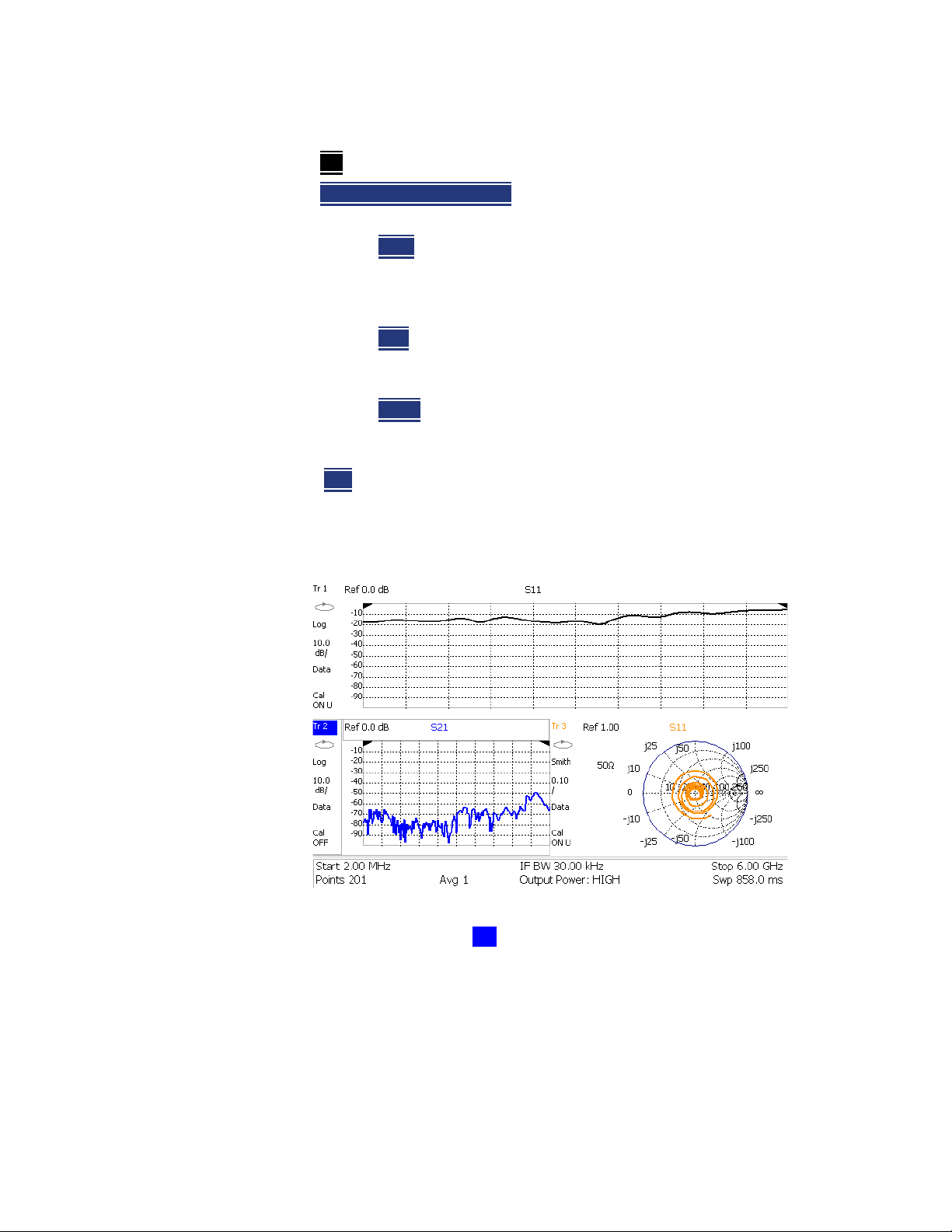
5-
NA (Network Analyzer) Mode
NA Mode Settings
— Then choose from the following:
(default) No conversion is performed.
—Off
—Z Conv (--) or Y Conv (--)
admittance (Y). Then choose from the following for either:
——Auto
The displayed S-parameter is converted to the
appropriate Z or Y parameter: Refl for S11 and S22; Trans for
S21 and S12. When the S-parameter is changed, the
appropriate conversion changes automatically.
——Refl
The displayed S-parameter is converted to Z or Y
reflection, regardless of whether the S-parameter is reflection
(S11 or S22) or transmission (S21 or S12).
——Trans
The displayed S-parameter is converted to Z or Y
transmission, regardless of whether the S-parameter is
reflection (S11 or S22) or transmission (S21 or S12).
— 1/S
The displayed S-parameter is converted to 1/S-parameter.
Multi-Trace Configurations
In NA Mode you can display multiple traces on the FieldFox screen.
Perform conversion for impedance (Z) or
The graphic above shows a x3H configuration. Tr2 is the ACTIVE trace as
indicated by the highlighted Tr2.
Trace Setting Notes
— The Frequency Range, IF BW, Resolution, Average, and Output Power
settings are common for all displayed traces.
— All other trace settings, such as measurement, format, and limit lines, are
applied individually to the ACTIVE trace in the same manner as when a
single trace is present.
5- 4 Keysight N9912-90001 User’s Guide
Page 69
NA (Network Analyzer) Mode
NA Mode Settings
— By default, a marker is created on ALL traces. However, they can be created
individually by disabling Coupled Markers. Learn more in “Coupled Markers
(NA Mode)” on page 16-5.
How to select a multi-trace configuration
—Press Trace 6
—Then Num of Traces
.
.
— Then choose from the following:
The default measurements depend on the options that are installed
x1
x2
x2H
x3H
x3
x4H
1 trace standard configuration
2 traces overlayed on a single graticule
2 traces on separate graticules
3 traces on separate graticules
3 traces overlayed on a single graticule
4 traces on separate graticules
How to activate a trace in order to change a setting
—Use the arrows OR
—Press Trace 6
then select Trace 1, Trace 2, Trace 3, or Trace 4, Only traces
that are shown can be activated.
How to maximize the viewing of the active trace
—Press System 7.
—Then Full Screen
.
— Press any key to return to the standard display.
Quick Settings
Both CAT and NA Modes allow you to view and change most relevant settings
from a single location. All of these settings are discussed in this chapter and,
unless otherwise noted, ALL of these settings can also be made using the
standard softkey menus.
Keysight N9912-90001 User’s Guide 5- 5
Page 70
5-
NA (Network Analyzer) Mode
NA Mode Settings
How to view and change Quick Settings
—Press Meas Setup 4
—Then Settings
—Press Next Page
.
.
and Previous Page to view all settings. If these softkeys
are NOT available, then all available settings fit on one page.
—To change a setting:
—Use the arrows to highlight a setting.
—Then press Edit
. The current setting changes to yellow.
—Some settings require you to press a softkey to change the value.
Otherwise, use the numeric keypad, arrows, or rotary knob to
change the value.
—When finished changing a value, press Done Edit
—Press Dock Window
to relocate the Settings table to a position relative to
.
the trace window. The Dock Window setting persists through a Preset.
Choose from the following:
—Full (Default setting) Only the Settings table is shown on the screen.
The trace window is temporarily not shown.
—Left The Settings table is shown to the left of the trace window.
—Bottom The Settings table is shown below the trace window.
When finished changing ALL settings, press Done
Calibration Settings
NA Mode has a page specifically for making settings that pertain to Port
Extensions, including Velocity Factor and Media Type.
Learn more in “Port Extensions” on page 5-16.
Learn how to calibrate beginning in “Why and When to Calibrate” on
page 7-2.
The N9912A does NOT support Media Type: Waveguide.
How to view and change Cal ibration Settings
—Press Meas Setup 4
—Then Calibration Settings
— Make these settings in the same manner as Quick Settings in the previous
section.
to save your settings.
.
.
5- 6 Keysight N9912-90001 User’s Guide
Page 71
Format
NA (Network Analyzer) Mode
NA Mode Settings
Select the display format in which to present measurement results. This setting
can be changed at any time without affecting calibration accuracy.
Learn more about Display Formats in the FieldFox Supplemental Online
Help:
http://na.support.keysight.com/fieldfox/help/SupHelp/FieldFox.htm
The marker on screen readout can be changed to formats other than the
display format. Learn more in “Marker Functions” on page 16-12.
How to select a NA Format
—Press Measure 1
—Then Format [current setting]
.
.
— Then choose from the following:
— Log Magnitude
— Linear
Displays positive values only. Y-axis: Unitless (U) for ratioed
Displays magnitude in dB
measurements; Watts (W) for unratioed measurements.
— VSWR
— Phase
Used mainly for S11 and S22. Displays unitless reflection data.
Displays phase in degrees. The trace ‘wraps’ every 360
degrees, from +180 to –180, for easy scaling.
— Smith
Used mainly for S11 and S22, which are plotted on a Smith
Chart. Displays series resistance and reactance.
— More
— Polar
then…
(S11 Only). Displays magnitude and phase of the reflection
coefficient.
— Group Delay
Used mainly (S11) only. Displays propagation time (in
seconds) from the RF port to the point where it is reflected, and back
to the A receiver. The aperture setting is the frequency
range/(number of points – 1). Use Smoothing as the Group Delay
aperture.
——Learn how to set Smoothing aperture on “Smoothing” on
page 5-12.
——Learn more about Group Delay measurements at the FieldFox
Supplemental Online Help:
http://na.support.keysight.com/fieldfox/help/SupHelp/FieldF
ox.htm
Keysight N9912-90001 User’s Guide 5- 7
Page 72
5-
NA (Network Analyzer) Mode
NA Mode Settings
— Unwrap Phase Same as Phase, but without 180 degree wrapping.
Phase is unwrapped by comparing the phase from one data point to the
next. If the phase difference between two data points is greater than 180
degrees, or if the phase of the first data point is greater than 180 degrees
from DC, than the phase measurement is probably NOT accurate. To
ensure that the phase measurement is accurate, increase the resolution
setting. When making a narrow band measurement, reduce the start
frequency for the unwrapped phase measurement to ensure the first data
point is less than 180 degrees from DC.
Frequency Range
Set the range of frequencies over which you would like to make measurements.
When the frequency range is changed after a calibration is performed, the cal
becomes interpolated. Learn more in “Interpolation” on page 7-7.
How to set Frequency Range
This can be done in two ways:
—Press Freq/Dist
— Then choose from the following:
— Start
— Center
— Follow each by entering a value using the numeric keypad, the arrows,
or the rotary knob.
— After using the arrows or the rotary knob, press Enter
setting of the arrows is based on the current span and can NOT be changed
in NA Mode.
— After using the keypad, select a multiplier key. Learn more in “Multiplier
Abbreviations” on page 2-14.
Scale Settings
.
and Stop frequencies – Specify the beginning and end of the
sweep.
and Span frequencies - Specify the center frequency and
span of frequencies (half on either side of center).
. The increment
Adjust the Y-axis scale to see the relevant portions of the data trace. The Y-axis
is divided into 10 graticules.
This setting can be changed at any time without affecting calibration accuracy.
How to set Scale
—Press Scale / Amptd
5- 8 Keysight N9912-90001 User’s Guide
.
Page 73
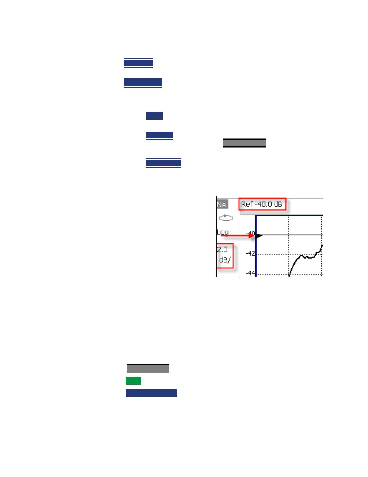
NA (Network Analyzer) Mode
NA Mode Settings
— Then choose from the following methods:
—Autoscale
Automatically adjusts the Y-axis to comfortably fit the Min
and Max amplitude of the trace on the screen.
—Autoscale All
Autoscales all of the traces on the screen, useful only for
multi-trace configurations.
—3.Set Scale, Reference Level, and Reference Position
——Scale
Manually enter a scale per division to view specific areas
of the trace.
——Ref Level
Manually set the value of the reference line. Enter a
negative value by pressing Run/Hold (+/-)
after typing a value.
——Ref Position
Manually set the position of the reference line.
Values must be between 0 (TOP line) and 10 (BOTTOM line)
Scale annotation on the FieldFox screen
—Reference Line = red arrow
—Ref Level = –40 dB
—Ref Position = 1
—Scale = 2 dB per division
either before or
Magnitude Offset
Magnitude Offset allows you to offset the magnitude (not phase) data by a
fixed and/ or sloped value in dB. If the display format is Linear Magnitude or
Real (unitless), the conversion from dB is performed and the correct amount of
offset is implemented.
The Magnitude offset setting affects only the active trace.
How to set Magnitude Offset
—Press Scale / Amptd
—Then More
.
—Then Magnitude Offset
value.
Keysight N9912-90001 User’s Guide 5- 9
.
- Offsets the entire data trace by the specified
Page 74
5-
NA (Network Analyzer) Mode
NA Mode Settings
— Then enter a positive or negative offset value in dB using the numeric
keypad, the arrows, or the rotary knob. Press a multiplier key.
Learn about “Multiplier Abbreviations” on page 2-14.
—And/or press Slope
with frequency. The offset slope begins at 0 Hz. and continues to the stop
frequency. The offset value at the start frequency is then calculated from 0
Hz.
— Then enter a positive or negative offset slope value in dB/GHz using
Electrical Delay
Electrical delay is a mathematical function that simulates a variable length of
lossless transmission line. Use the electrical delay feature to compensate for
the linear phase shift through a device and view only the deviation from linear
phase of the device.
You can set the electrical delay independently for each measurement trace. To
apply an electrical delay to all measurement traces, use Port Extensions. Learn
how in “Port Extensions” on page 5-16.
Learn how to set Phase formats in page 5-7.
How to set Electrical Delay
- Offsets the data trace by a value that changes linearly
the numeric keypad, the arrows, or the rotary knob. Press a
multiplier key. Learn about “Multiplier Abbreviations” on page 2-14.
—Press Scale / Amptd
—Then More
—Then Electrical Delay
— Enter a time value using the numeric keypad, the arrows, or the rotary
knob.
— Press a multiplier key. Learn about multiplier abbreviations in “Multiplier
Abbreviations” on page 2-14.
Electrical Delay can also be set using the Mkr->Delay feature. Learn how on
“Marker Functions” on page 16-12.
Phase Offset
Phase formate is available only with S11 measurements.
Phase offset mathematically adjusts the phase measurement by a specified
amount, up to 360°. Use this feature in the following ways:
Improve the display of a phase measurement. This is similar to the way you
would change the reference level in an amplitude measurement. Change the
phase response to center or align the response on the screen.
.
.
.
5- 10 Keysight N9912-90001 User’s Guide
Page 75
NA (Network Analyzer) Mode
NA Mode Settings
Emulate a projected phase shift in your measurement. For example, if you
know that you need to add a cable and that the length of that cable will add a
certain phase shift to your measurement, you can use phase offset to add that
amount and simulate the complete device measurement.
You can set the phase offset independently for each measurement trace.
How to set Phase Offset
—Press Scale / Amptd
—Then More
—Then Phase Offset
— Enter a value in degrees using the numeric keypad, the arrows, or the
Averaging
Averaging helps to reduce the effects of random noise on a measurement. You
specify the number of measurements to be averaged. The more measurements
averaged, the greater the amount of noise reduction. An average counter is
shown in the left edge of the screen as Avg <n> where <n> is the number of
measurements that are averaged.
Averaging can be set before or after calibration. When set before calibration,
each calibration standard is measured <n> times and averaged. More time is
needed to perform the calibration, but there will be less noise in the resulting
error terms which means that subsequent measurements will also have less
noise. In addition, noise is further reduced by continuing to average after
calibration.
How to set Averaging
.
.
.
rotary knob. Press Enter
.
—Press BW 2
—Then Average <n>
.
where <n> is the number of measurements to average.
— Enter a value using the numeric keypad. Enter 1 for NO averaging.
—Press Enter
—Then Average Mode
.
Choose from the following:
— Sweep - Each data point is based on the average of the same data
point being measured over <n> consecutive sweeps. The average
counter shows the number of previous sweeps that have been
averaged together to form the current trace. When the counter
reaches the specified count, then a ‘running average’ of the last <n>
sweeps is displayed.
Keysight N9912-90001 User’s Guide 5- 11
Page 76
5-
NA (Network Analyzer) Mode
NA Mode Settings
— Point - Each data point is measured <n> times and averaged before
going to the next data point. On subsequent sweeps, averaging
restarts by measuring each data point again <n> times. The average
counter is not updated because data is not displayed until all the
averages have been applied.
— Point averaging is usually faster than sweep averaging. However,
you may need to increase the Point Average count to obtain the same
level of noise reduction as with sweep averaging.
— While averaging is in process, press Sweep 3
averaging at 1.
IF Bandwidth
The FieldFox converts the received signal from its source to a lower
intermediate frequency (IF). The bandwidth of the IF bandpass filter is
adjustable. Reducing the IF receiver bandwidth reduces the effect of random
noise on a measurement. However, narrower IF bandwidths cause longer
sweep times.
How to set IF BW
—Press BW 2
—Then IF BW
— Then choose from the following:
— 300 Hz
Smoothing
Trace smoothing averages a number of ad jacent data points to smooth the
peak-to-peak noise values on a displayed trace. The number of adjacent data
points that are averaged is known as the smoothing aperture. Aperture is set
by specifying a percentage of the X-axis span.
then Restart to restart the
.
.
| 1 kHz | 3 kHz | 10 kHz | 30 kHz
Trace smoothing does NOT significantly increase measurement time.
Smoothing is used in Group Delay measurements, although it can be used with
any NA formatEXCEPT Polar or Smith Chart. Learn more about NA Mode
formats, including Group Delay, in “Format” on page 5-7.
When enabled, Smo appears on the FieldFox screen.
How to set Smoothing
—Press BW 2.
—Then Smoothing ON OFF
—Then Sm. Aperture
numeric keypad.
5- 12 Keysight N9912-90001 User’s Guide
.
and enter a value between 0 and 25 (percent) using the
Page 77
NA (Network Analyzer) Mode
NA Mode Settings
—Press Enter.
Single or Continuous Measure
This setting determines whether the FieldFox sweeps continuously or only once
each time the Single
or to allow you to save or analyze a specific measurement trace.
This setting can be changed at any time without affecting calibration accuracy.
How to set Single or Continuous
—Press Sweep 3.
— Then choose one of the following:
button is pressed. Use Single to conserve battery power
— Single
make ONE measurement, then hold for the next Single key press.
When a data trace is displayed, the entire trace is measured, then
holds. The Hold annotation changes to an arrow --> while the
measurement occurs.
— Continuous
when battery power is not critical.
— You can also use Run / Hold +/-
Automatically sets Continuous OFF and causes FieldFox to
Makes continuous sweeps. This is the typical setting
Resolution (Number of Data Points)
Data points are individual measurements that are made and plotted across the
X-axis to form a trace. Select more data points to increase measurement
resolution. However, more data points also takes more time to complete an
entire measurement sweep.
When the Resolution is changed after a calibration is performed, the cal
becomes interpolated. Learn more in “Interpolation” on page 7-7.
How to set Resolution
—Press Sweep 3
—Then Resolution
.
.
to toggle between Single and Continuous.
— Then choose from the following:
|201 | 401 | 601 | 801 | 1001 | 1601 | 4001 | 10001.
101
— Using SCPI, Resolution can be set to ANY number of points between 3 and
10001. See the Programming Guide at
http://na.support.keysight.com/fieldfox/help/Programming/webhelp/FFP
rogrammingHelp.htm
Keysight N9912-90001 User’s Guide 5- 13
Page 78
5-
NA (Network Analyzer) Mode
NA Mode Settings
Sweep Time
The fastest possible sweep time is always used as the default setting. Use the
Min Swp Time setting to slow the sweep time when measuring long lengths of
cable. Learn more at the FieldFox Supplemental Online Help:
http://na.support.keysight.com/fieldfox/help/SupHelp/FieldFox.htm
The actual sweep time is shown on the FieldFox screen. See the Screen Tour
on “Screen Tour” on page 2-12. To increase the sweep time, enter a value that
is higher than the actual sweep time. The increase will not be exactly the
amount that you enter, as the actual sweep time is the composite of many
factors.
Measurement speed specifications do NOT apply in Temperature Control
Mode. Learn more in
How to set Sweep Time
“Temperature Control Mode” on page 2-5.
—Press Sweep 3
—Then Min Swp Time
— Enter a value using the numeric keypad.
— Press a multiplier key. Learn about multiplier abbreviations in “Multiplier
Abbreviations” on page 2-14.
Output Power
Set the power level out of the FieldFox to High, Low, or manually set power
level to a value between High and Low.
Generally, the high power setting is used when measuring passive, high-loss
devices to place the signal farther from the noise floor. However, for devices
that are sensitive to high power levels such as amplifiers, use the Low power
setting.
For best measurement accuracy, use the Manual power setting at -15 dBm.
After calibration, the power level can be decreased for amplifiers, or increased
for higher dynamic range.
Power Level settings in this mode will NOT change Power Level settings in
other modes. To help prevent damage to your DUT, use caution when
changing modes with your DUT connected to the FieldFox test ports.
.
.
How to set Output Power
—Press Meas Setup 4.
—Then Output Power
5- 14 Keysight N9912-90001 User’s Guide
.
Page 79
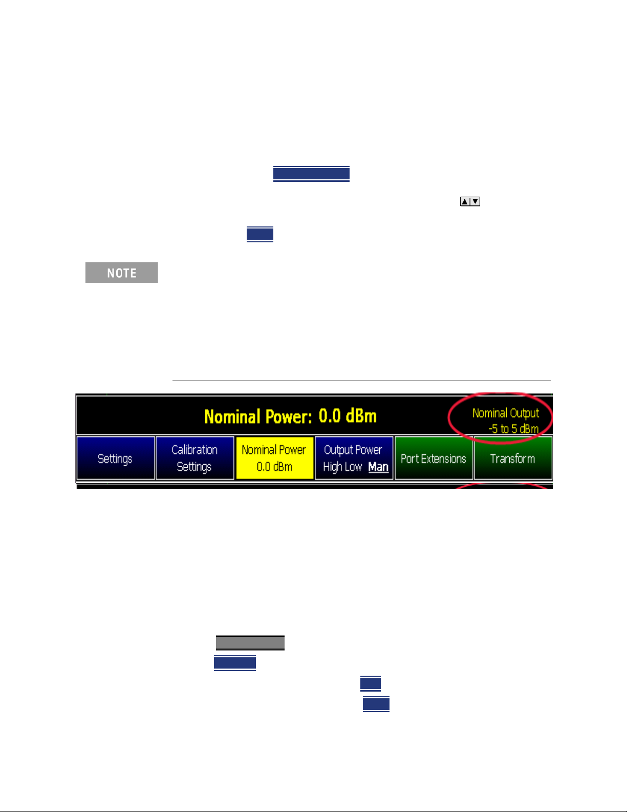
NA (Network Analyzer) Mode
NA Mode Settings
— High (Default setting) Sets output power to the maximum achievable
power at all displayed frequencies. Please see the FieldFox
Specifications (page B-3) for expected power levels.
— Low Sets output power to approximately –27 dBm.
— Man Set output power to a arbitrary value.
—Then press Nominal Power
— Then enter a value using the numeric keypad, the arrows, or the
rotary knob.
—Press Enter
Nominal here means: a general, descritive term or design parameter. It is
not tested and not covered by the product warranty.
The Nominal Output displayed on the bottom right side of the display
indicates a range of low and high power values. Your actual measured
output power could be a little lower or a little higher.
If you have the USB power sensor feature (Option 302) you can measure
the actual output power for your measurement. Refer to “Power Meter
Mode (Option 302)” on page 11-1.
.
.
System Impedance (Z0)
To accurately view data presented in Smith Chart format, first set the System
Impedance.
Learn how to select Smith Chart format in “Format” on page 5-7.
Learn how to make 75Ω measurements at the FieldFox Supplemental Online
Help: http://na.support.keysight.com/fieldfox/help/SupHelp/FieldFox.htm
How to set System Impedance
—Press Meas Setup 4
—Then Settings
— Then scroll to System Z0 and press Ed it
— Then type either 50 or 75 and press Enter
Keysight N9912-90001 User’s Guide 5- 15
.
.
.
.
Page 80
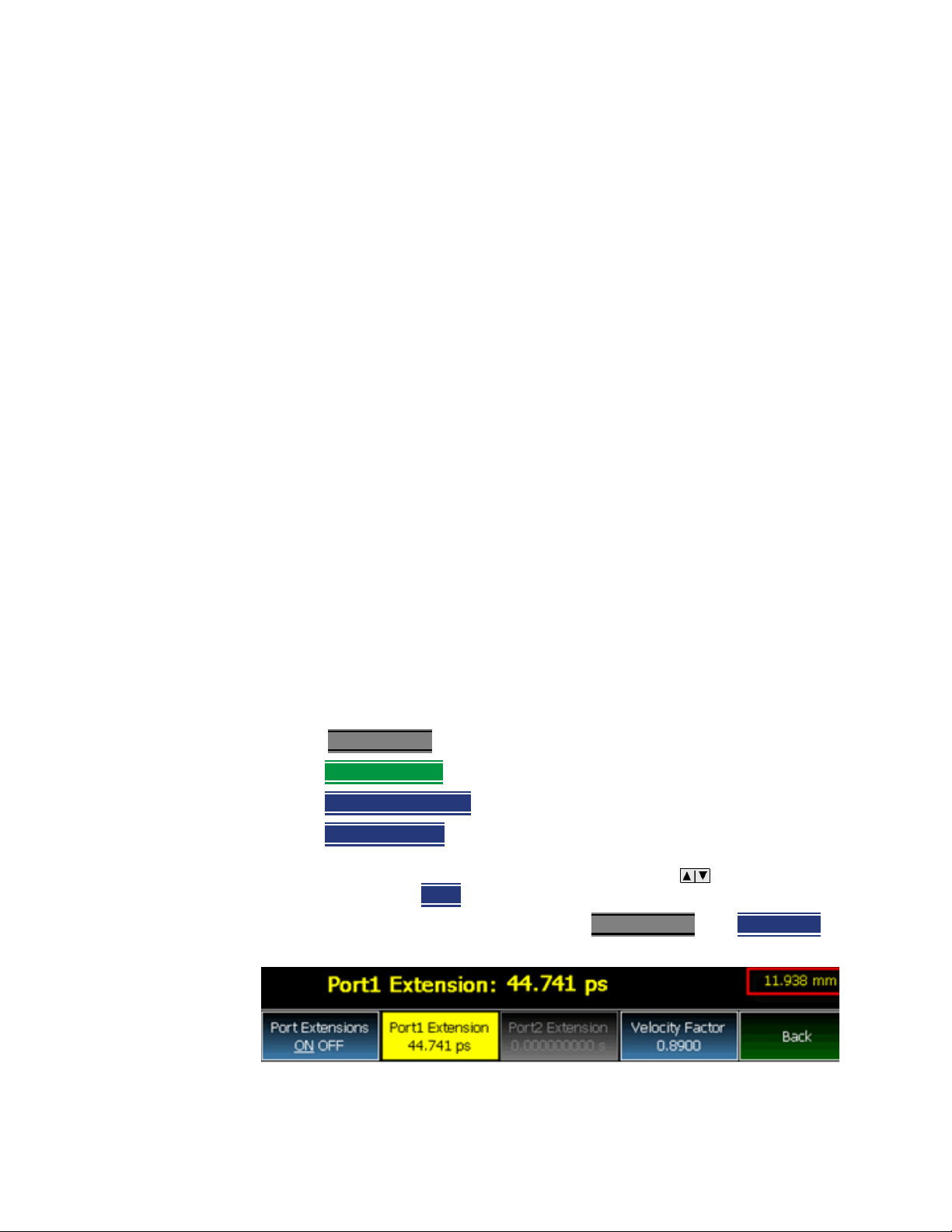
5-
NA (Network Analyzer) Mode
NA Mode Settings
Port Extensions
Port extensions allow you to electrically move the calibration reference plane
on either port 1 after you have performed a calibration.
Phase measurements, and therefore Port Extensions, are NOT available on port
2.
Why use Port Extensions
Use port extensions if you are unable to perform a calibration directly at your
device because the location is not accessible. Perform a calibration at a
convenient place, then use port extensions to compensate for the time delay
(phase shift) to the desired reference plane. On the FieldFox, port extensions
does not compensate for the loss of the additional electrical length, nor any
mismatch errors beyond the calibration reference plane.
Also use port extensions if you have already performed a calibration, and then
decide that you need to add a length of transmission line in the measurement
configuration. Use port extensions to “tell” the FieldFox that you have added
the length to a specific port.
Port extensions and Electrical Delay differ in the following ways:
— Electrical delay is applied to a specific trace.
— Port extensions are applied to specific trace.
Port Extensions and Electrical Delay can be set independently. When both are
set, the delay adds together. Learn more about Electrical Delay in “Electrical
Delay” on page 5-10.
How to apply Port Extensions
—Press Meas Setup 4.
—Then Port Extensions
—Then Port Extensions ON
—Then Port1 Extension
— Then enter time value using the numeric keypad, the arrows, or the
rotary knob. Press Enter
You can also set Port Extensions by pressing Meas Setup 4
(settings).
.
.
.
or select a seconds (time) multiplier.
then Calibration
5- 16 Keysight N9912-90001 User’s Guide
Page 81
NA (Network Analyzer) Mode
NA Mode Settings
While setting Port Extension, the physical length of the extension, at the
current Velocity Factor setting, is visible to the right (red box in above
image).
Velocity Factor
The electrical delay or port extension value is entered as delay, or electrical
length, in units of time.
Entering the velocity factor causes the FieldFox to accurately display the
equivalent physical length in meters (NOT available in feet) that corresponds
to the entered electrical delay.
Velocity factor is the ratio of the velocity of wave propagation in a coaxial cable
to the velocity of wave propagation in free space. This velocity depends on the
relative permittivity of the cable dielectric (er).
Velocity factor = 1/sqrt(er)
VF = 0.66 corresponds to wave propagation through a polyethylene dielectric.
VF = 1.0 (default setting) corresponds to wave propagation through free space
(a vacuum).
How to set Velocity Factor
—Press Meas Setup 4
—Then Port Extensions
—Then Velocity Factor
— Then enter a value between 0.1 and 1 using the numeric keypad, then press
.
Enter
You can also set Velocity Factor by pressing Meas Setup 4
(settings).
.
.
.
S21Transmission Measurements
An S21 Transmission measurement, available with option 110, is used to
measure the loss through a DUT – or cable – over a specified frequency range.
The FieldFox signal source is transmitted out the RF OUT connector, through
the DUT, and into the RF IN connector. Both ends of the DUT must be
connected to the FieldFox.
An S21 measurement is exactly the same measurement as “2-Port Insertion
Loss” in CAT Mode.
then Calibration
A Normalization Cal is REQUIRED when making 2-port CAT or NA
measurement.
For highest accuracy, when measuring the DUT also attach any cable or
adapter that was used in the normalization cal.
Keysight N9912-90001 User’s Guide 5- 17
Page 82
5-
NA (Network Analyzer) Mode
NA Mode Settings
How to make an S21 Transmission Measurement
1. Press Node
2. Press Freq/Dist
then NA then S21 Transmission.
and enter Start and Stop frequency values of the
measurement.
3. Press Sweep 3
4. Press Cal 5
then select a Resolution setting.
then press Normalization. Perform normalization as explained
on page 7-6.
5. Connect the DUT and view the transmission measurement results.
When measuring very long lengths of cable, it may be necessary to increase
the sweep time. Learn how in “Sweep Time” on page 3-8. Learn why at the
FieldFox Supplemental Online Help:
http://na.support.keysight.com/fieldfox/help/SupHelp/FieldFox.htm
Big Marker Display States (A and B)
This feature, available ONLY in NA Mode, allows you to view up to three Big or
Super Big marker readouts. This is done by using up to two different display
states called A and B. Each display state is comprised of the settings listed
below. When the Big Readout setting is toggled through A and B, these display
states are recalled.
How to create Big Marker Display States
To have big readouts, markers MUST be created using the following procedure.
If you have already set up your display and do not want to lose it, then save the
current state to a state file. Learn how in “State Files” on page 17-4. The
following procedure will overwrite your display state.
—Press Mkr ->/ Tools
—Then Big Readout
.
.
— A or B - The A or B display state is recalled. If none have been
defined, then the default display state is recalled.
— OFF - The B display state is visible but without the Big Marker
Readout.
— With A or B selected, then press Edit Big Marker (A or B)
.
— Then edit the following display state settings:
— Num Traces – Choose the Multi-Trace configuration x1, x2, or x3. Only
Overlayed configurations are allowed. Learn more in “Multi-Trace
Configurations” on page 5-4.
— Font Size – Choose either Big or Super Big. Super Big marker readout #3
will cover some of the measurement grid.
5- 18 Keysight N9912-90001 User’s Guide
Page 83

NA (Network Analyzer) Mode
NA Mode Settings
— Trace Settings - For each possible trace (1, 2, and 3) select from the
following:
— Measurement – S-Parameter or Receiver measurement to display.
S11 is default. Learn more in “Measurement Selection” on page 5-3.
— Meas Format – Log is default. Learn more in “Format” on page 5-7.
— Band width (ON) – Marker readout for marker bandwidth search.
OFF is default. Learn how to set BW parameters in “How to Search
with Markers” on page 13-12.
— Big Readout - For each marker readout (1, 2, and 3), select from the
following:
— Marker # - Enter a number from 1 to 6 to create the marker. 1 is
created by default.
— Trace # - The marker# is created on this trace. Tr1 is selected by
default. The corresponding Num Traces must first be selected. For
example, to create a marker on Trace 3, first select Num Traces = x3.
— Format – Format for the marker readout. Select Default to make the
marker readout format the same as the display format. Default is
selected by default.
— Mkr Tracking – ON: Select the parameter to track on the standard
Marker Search menu. OFF is selected by default. When set to ON,
Peak tracking is set by default. Learn about Marker Tracking in
“Searching with Markers” on page 16-7.
— State – Choose from Normal, Delta, or OFF. The default marker (1) is
created in Normal. Learn more in “Marker Functions” on page 16-12.
— Enabled – Turns the Big Readout of the corresponding marker ON
and OFF. The default marker (1) is set ON by default.
Notes:
— To move a marker, press Marker, then Marker, then scroll to the marker
number to be moved. The new marker position can NOT be saved with the A
or B display state.
— Settings that are NOT listed above are NOT affected by the recalled display
states.
— Changes to the above settings outside the Big Readout menu will be
overwritten when Big Readout (A or B) is selected. For example, suppose
the display format for the B state is Log. If you change the display format to
Lin using the standard menu (Meas 1, Format), the setting will show on the
display. But if you then use the Big Readout (A | B | OFF) setting, when B is
recalled, the Lin setting will be overwritten with the original Log setting.
Keysight N9912-90001 User’s Guide 5- 19
Page 84
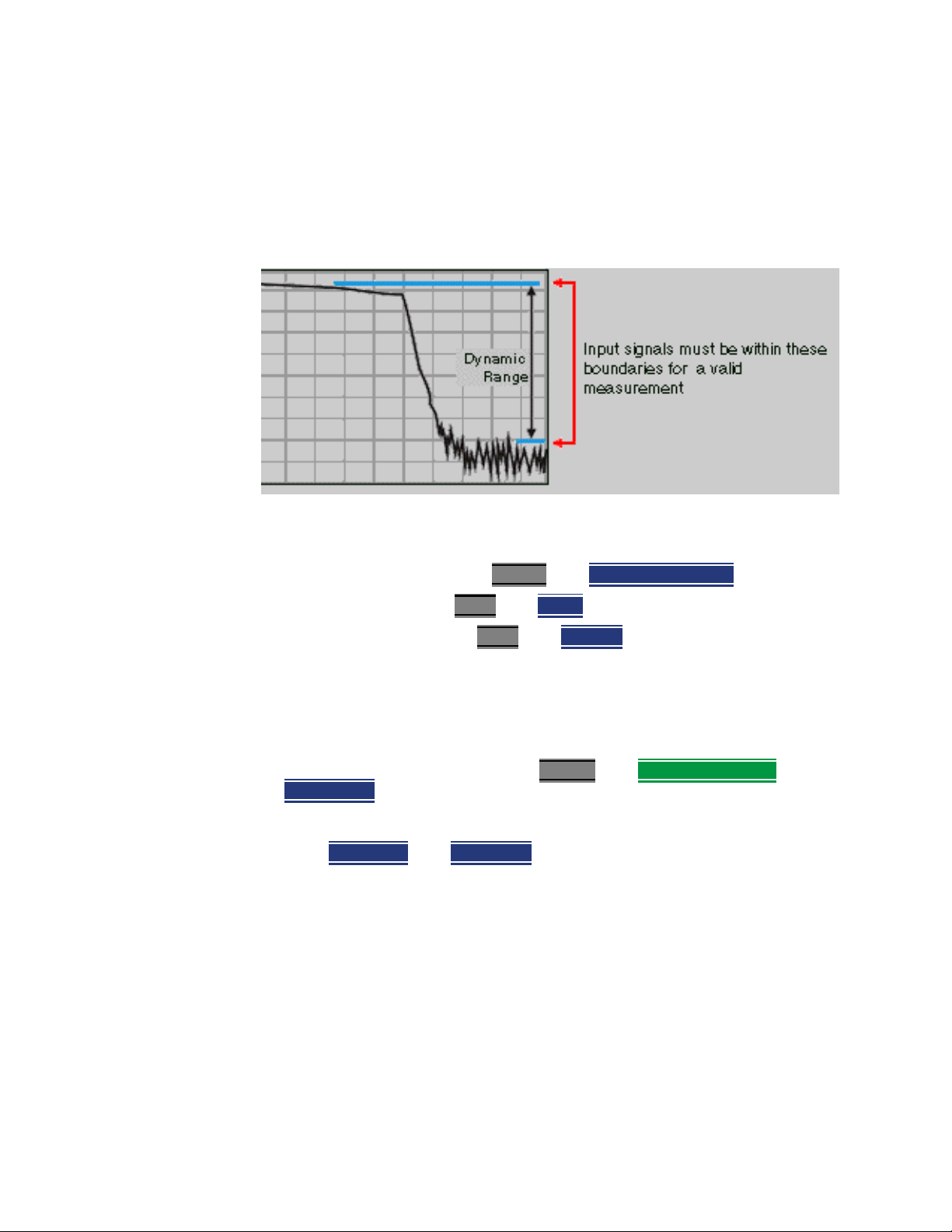
5-
NA (Network Analyzer) Mode
NA Mode Settings
Increase Dynamic Range
Dynamic range is the difference between maximum input power to the
FieldFox receiver (without compressing the receiver), and the minimum
measurable power (noise floor). Measurement accuracy is increased when the
DUT response is at least 10 dB above the noise floor. For a measurement to be
valid, input signals must be within these boundaries.
The following settings will increase the dynamic range of your NA mode
measurement.
— Increase Power Level: Press Meas 4
— Lower the IFBW: Press BW 2
then IF BW.
— Increase Averaging: Press BW 2
then Output Power High.
then Average.
The following procedure MAY increase the dynamic range of your NA mode
measurement. The results you see will depend on the performance of your
DUT.
With an S21 trace active:
1. With RF OUT (port-2) open, press Trace 6
Data->Mem
.
then Math and Memory then
2. Re-connect the DUT.
3. Press Data Math
then Data-Mem.
5- 20 Keysight N9912-90001 User’s Guide
Page 85

Keysight Handheld Analyzers
N9912A User’s Guide
6 Time Domain – Option 010
With NA Mode, Time Domain Reflectometry (Opt 010), frequency information is
used to calculate and display measurements with time as the horizontal
display axis. The response values appear separated in time allowing a different
perspective of the test device's performance and limitations.
NA Mode settings that are NOT unique to Time Domain are documented in
Chapter 5, “NA (Network Analyzer) Mode”, on page 5-1.
In This Chapter
“Overview” on page 6-3
Time Domain (Transform) Settings
“Transform Settings Table” on page 6-4
“Frequency Range and Points” on page 6-4
“Stimulus (Mode)” on page 6-5
“Set Frequency Lowpass” on page 6-5
“Start/Stop Time” on page 6-5
“Distance Units” on page 6-6
“Window Layout” on page 6-6
“Transform Window” on page 6-6
“Line Loss and Velocity Factor” on page 6-7
“Data Chain” on page 6-8
Trace Settings
“Transform Enable” on page 6-9
“Gate Enable” on page 6-9
6- 1
Page 86

6-
Time Domain – Option 010
Gating Settings
“Start, Stop, Center, and Span Gate Times” on
page 6-10
“Gating Type” on page 6-10
6- 2 Keysight N9912-90001 User’s Guide
Page 87
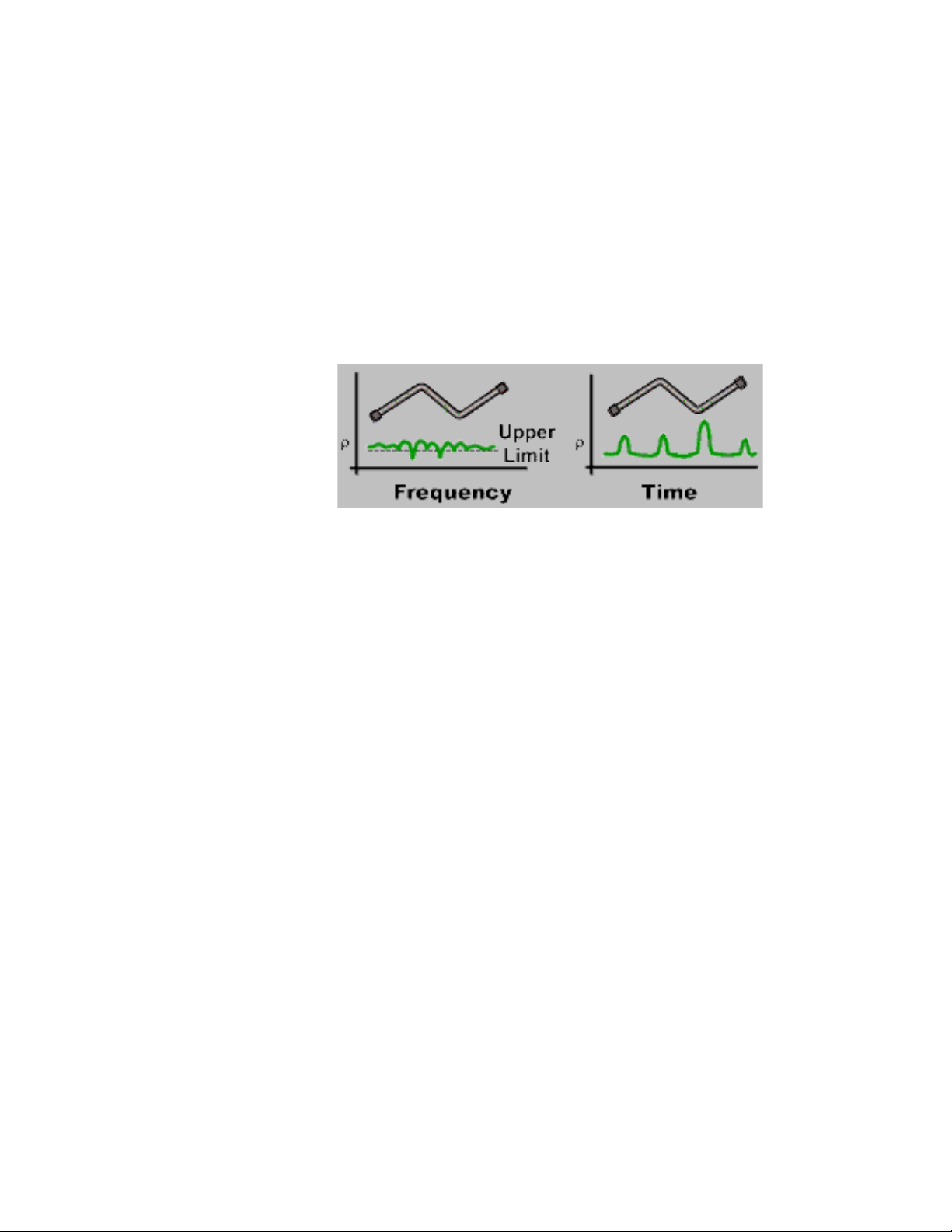
Overview
Time Domain – Option 010
Overview
In normal NA Mode operation, the FieldFox measures the characteristics of a
test device as a function of frequency. With Time Domain (opt 010), frequency
information is used to calculate the inverse Fourier transform and display
measurements with time on the horizontal display axis. The response values
appear separated in time, allowing a different perspective of the test device's
performance and limitations.
The graphic below compares the same cable reflection measurement data in
both the frequency and time domain. The cable has two bends. Each bend
creates a mismatch or change in the line impedance.
The frequency domain of an S11 measurement shows reflections caused by
mismatches in the cable. It is impossible to determine where the mismatches
physically occur in the cable.
The Time Domain response shows both the location and the magnitude of each
mismatch. The responses indicate that the second cable bend is the location of
a significant mismatch. This mismatch can be gated out, allowing you to view
the frequency domain response as if the mismatch were not present. Learn
more about gating in “Gating” on page 6-10.
Markers that are created on a Time Domain trace can be used to pinpoint the
distance of the mismatch from the reference plane.
For more information on Time Domain theory, see
http://literature.cdn.keysight.com/litweb/pdf/5989-5723EN.pdf
Keysight N9912-90001 User’s Guide 6- 3
Page 88
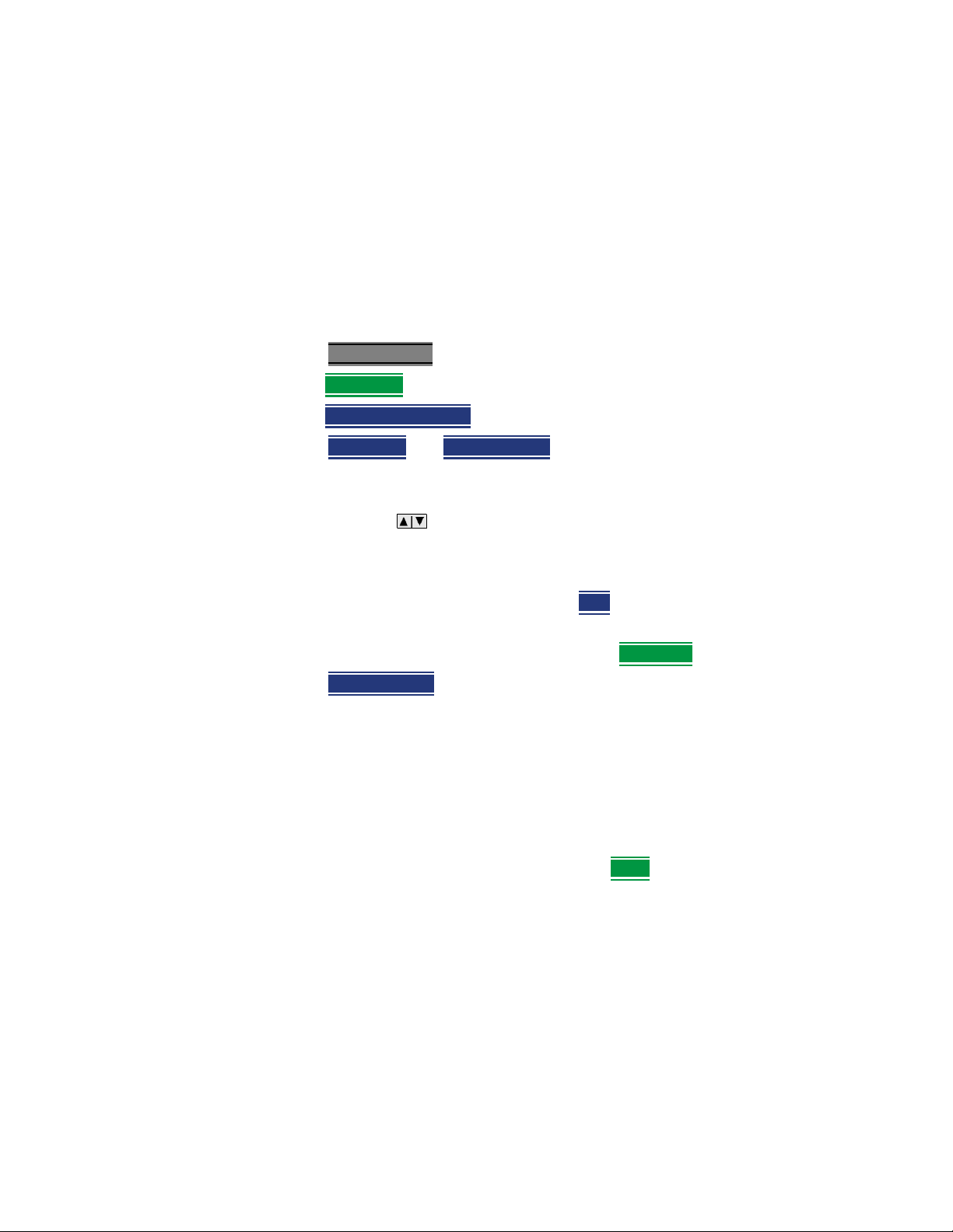
6-
Time Domain – Option 010
Time Domain (Transform) Settings
Time Domain (Transform) Settings
You can set and view most of the Time Domain settings on the Transform
Settings table.
Transform Settings Table
The following settings (from Transform Stimulus Settings to Data Processing)
are listed in the order they appear on the Transform Settings menu selection.
How to make settings on the Transform settings table
—Press Meas Setup 4
—Then Transform
—Then Transform Settings
—Press Next Page
—To change a setting:
— Use the arrows or rotary knob to highlight a setting.
— Numeric settings can be changed by pressing numbers using the
numeric keypad. Then press Enter or select a suffix if available.
— Some settings allow you to press Edit
settings require that you then press a softkey to change the value.
— When finished changing a value, press Done Edit
—Press Dock Window
the trace window. The Dock Window setting persists through a Preset.
Choose from the following:
— Full (Default setting) Only the Settings table is shown on the screen.
The trace window is temporarily not shown.
.
.
.
and Previous Page to view all settings.
to toggle the value. Other
.
to relocate the Settings table to a position relative to
— Left The Settings table is shown to the left of the trace window.
— Bottom The Settings table is shown below the trace window.
— When finished changing ALL settings, press Done
to save your settings.
Frequency Range and Points
Like CAT mode, all Time Domain measurements are made in the frequency
domain and, using Inverse Fourier Transform (IFT), time is calculated. Select
the frequency range from which Time Domain measurements are calculated.
Increasing the data points will improve measurement resolution. However,
more data points will usually result in slower sweep updates.
Set frequency range and points before selecting Stimulus Mode.
6- 4 Keysight N9912-90001 User’s Guide
Page 89
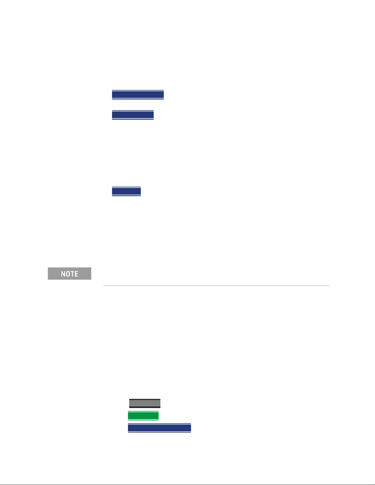
Time Domain – Option 010
Time Domain (Transform) Settings
Stimulus (Mode)
— There are three variations on how the Time Domain transform algorithm is
applied to the frequency domain measurement. Each method has a unique
application.
— Lowpass Impulse
responses in devices that pass low frequencies, such as cables.
— Lowpass Step
in devices that pass low frequencies such as cables.
In both Lowpass modes, frequencies down to DC and negative frequencies are
extrapolated. Therefore, when either Lowpass mode is selected, Set Freq.Low
Pass is automatically applied to adjust the start frequency. Learn more about
Set Frequency Lowpass below.
When the Start Frequency or resolution is changed AFTER selecting a Lowpass
mode, then Stimulus mode is set to Band Pass and Transform is disabled.
— Bandpass
useful for measuring band limited devices such as filters and DC blocked
cables. This mode does NOT show capacitive and inductive reactance. For
the same frequency span and number of points, band pass mode has twice
the impulse width, which hides closely spaced responses degrading the
response resolution.
- Easiest to identify inductive and capacitive discontinuities
- Easiest method - can be used with any frequency sweep. Most
Set Frequency Lowpass
This setting is made automatically when either Lowpass mode is selected.
- Highest resolution. Most useful for seeing small
USE ONLY IN LOW PASS MODES. When this setting is made, the start
frequency is adjusted to be harmonics of the start frequency. Start frequency is
computed by the following formula:
Low Pass Start Frequency = Stop Frequency / Number of points.
Start/Stop Time
The following settings adjust the d isplay resolution, allowing you to zoom IN
or OUT on a response. When the start or stop time is updated, they may be
automatically adjusted to limit the display to one alias-free response on either
side of zero time.
How to set Start and Stop time
—Press Measure 4
—Then Transform
—Then Transform Start Stop
Keysight N9912-90001 User’s Guide 6- 5
.
.
.
Page 90
6-
Time Domain – Option 010
Time Domain (Transform) Settings
— Then choose from:
— Start
— Stop
Zero (0) seconds is always the calibration reference plane. Negative values
are useful if moving the reference plane.
Distance Units
When markers are present on a Time Domain trace, marker X-axis values are
shown both in units of time (seconds) and distance. Select the units in which
the marker distance data is presented.
Distance Units are also used when setting Time Domain Line Loss. Learn more
in “Line Loss and Velocity Factor” on page 6-7.
Choose from: m (meters), or Feet.
Window Layout
This setting is used to create additional traces, or select a new layout for traces
that are already created,
Sets the transform start time that is displayed on the FieldFox
screen.
Sets the transform stop time that is displayed on the FieldFox
screen.
Choose from: x1, x2, x2H, x3H, x4H.
Learn more about “Multi-Trace Configurations” on page 5-4.
Transform Window
There are abrupt transitions in a frequency domain measurement at the start
and stop frequencies, causing overshoot and ringing in a Time Domain
response. The Window setting reduces the abruptness of the frequency domain
transitions. This causes you to make a trade off in the Time Domain response.
6- 6 Keysight N9912-90001 User’s Guide
Page 91
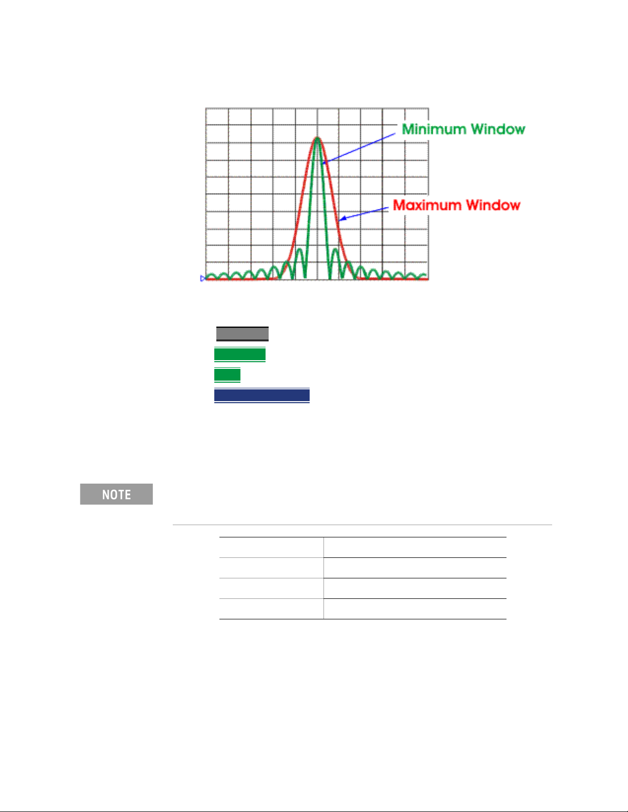
Time Domain – Option 010
Time Domain (Transform) Settings
The Window setting applies to ALL traces.
How to make Window setting
—Press Measure 4.
—Then Transform
—Then More
—Then Transform Window
.
.
.
— A settings table appears that allows you to navigate and select the
following settings. These settings are made exactly like those made on the
Transform Settings table. Learn how in “Transform Settings Table” on
page 6-4.
Any of the following four methods can be used to make this same Window
setting. Impulse Width values are calculated from the frequency span and
Kaiser Beta value.
1. Window Min Medium Max
2. Percent 0 50 100
3. Kaiser Beta 0 6.50 13.00
4. Impulse Width 100.455 ps 168.501 ps 231.284 ps
Line Loss and Velocity Factor
By default, the FieldFox does NOT correct Time Domain measurements to
account for the inherent loss of a cable. However, to make more accurate
measurements, Line Loss and Velocity Factor should be considered.
Keysight N9912-90001 User’s Guide 6- 7
Page 92

6-
Time Domain – Option 010
Time Domain (Transform) Settings
About Velocity Factor and Line Loss
— Velocity Factor is a property of the physical material of a cable. A VF of 1.0
corresponds to the speed of light in a vacuum, or the fastest VF possible. A
polyethylene dielectric cable has VF = 0.66 and a cable with PTFE dielectric
has VF = 0.7.
— Line Loss is specified in dB/m (or ft). In addition to the length of the cable,
loss is also directly proportional to the frequency of the signal that passes
through the cable.
The following is an example showing how Line Loss works:
The DUT is a 100 meter transmission cable. The Line Loss value is.1 dB/meter.
This means that a signal traveling ONE WAY through the cable will lose 10 dB
of power (100 m *.1dB/m). Because the FieldFox performs this measurement
with 1 port, the test signal travels down the cable and then back, for a total
loss of 20 dB.
For the purpose of illustrating this point, connect an OPEN to the end of the
cable – a maximum-sized fault - for 100% reflection of the 300 MHz test
signal.
Without compensation for the loss of the cable, a –20 dB response would be
visible at 100 meters, which is the OPEN at the end of the DUT. This is from 10
dB of loss through the cable in each direction.
With compensation for the loss using the manufacturer’s specification, the
FieldFox compensates the trace as though the signal traveling through 100
meters was increased by +20 dB. Therefore the response will show 0 dB for
100% reflection.
Data Chain
This setting, available only on the Transform Settings Table, reverts to the
default when the FieldFox is Preset. Choose from the following:
— Standard – The normal FieldFox data processing chain. Transform
— 8510 – The data processing chain used by the Keysight 8510 network
calculations are performed AFTER error correction and trace math.
analyzer. Transform calculations are performed BEFORE error correction
and trace math. Learn more at the FieldFox Supplemental Online Help
website:
http://na.support.keysight.com/fieldfox/help/SupHelp/FieldFox.htm
6- 8 Keysight N9912-90001 User’s Guide
Page 93
Trace Settings
Transform Enable
Time Domain – Option 010
Trace Settings
The following two settings apply to specific traces.
Enable Time Domain transform for the specific trace.
— Select the trace.
—Press Measure Setup 4
—Then Transform
— Then choose from:
Gate Enable
Enable Gating for the specific trace.
— Select the trace.
—Press Measure 4
—Then Transform
— Then choose from:
.
.
Trace displays Time Domain data.
— On
— Off
Trace displays frequency domain data.
.
.
Trace displays Time Domain data.
— On
Trace displays frequency domain data.
— Off
Keysight N9912-90001 User’s Guide 6- 9
Page 94
6-
Time Domain – Option 010
Gating
Gating
Perhaps the most beneficial feature of Time Domain transform is the Gating
function. When viewing the Time Domain response of a device, the gating
function can be used to “virtually” remove undesired responses. You can then
simultaneously view a frequency domain trace as if the undesired response did
not exist. This allows you to characterize devices without the effects of external
devices such as connectors or adapters.
Gating is best performed while viewing a Time Domain trace. Then, either
disable Transform, or separately view a frequency domain trace to see the
trace with the gated effects removed.
When a discontinuity in a test device reflects energy, that energy will not
reach subsequent discontinuities. This can “MASK”, or hide, the true
response which would have occurred if the previous discontinuity were not
present. The Gating feature does NOT compensate for this.
How to make Time Domain Gating settings
—Press Measure 4 .
—Then Transform
—Then Gating
— Then choose from:
Gating is being performed.
— On
— Off Gating is NOT being performed.
.
.
Start, Stop, Center, and Span Gate Times
These settings specify the time in the trace to be gated (in or out). The gate
times can be specified using either Start and Stop or Center and Span.
—Press Gating Start Stop
— A settings table appears that allows you to navigate and select the
following settings. These settings are made exactly like those made on the
Transform Settings table. Learn how in “Transform Settings Table” on
page 6-4.
.
Gating Type
This setting defines the type of filtering that will be performed for the gating
function. The gate start and stop flags on the display point toward the part of
the trace you want to keep.
Choose from the following:
— Bandpass
6- 10 Keysight N9912-90001 User’s Guide
KEEPS the responses within the Gating Start and Stop times.
Page 95
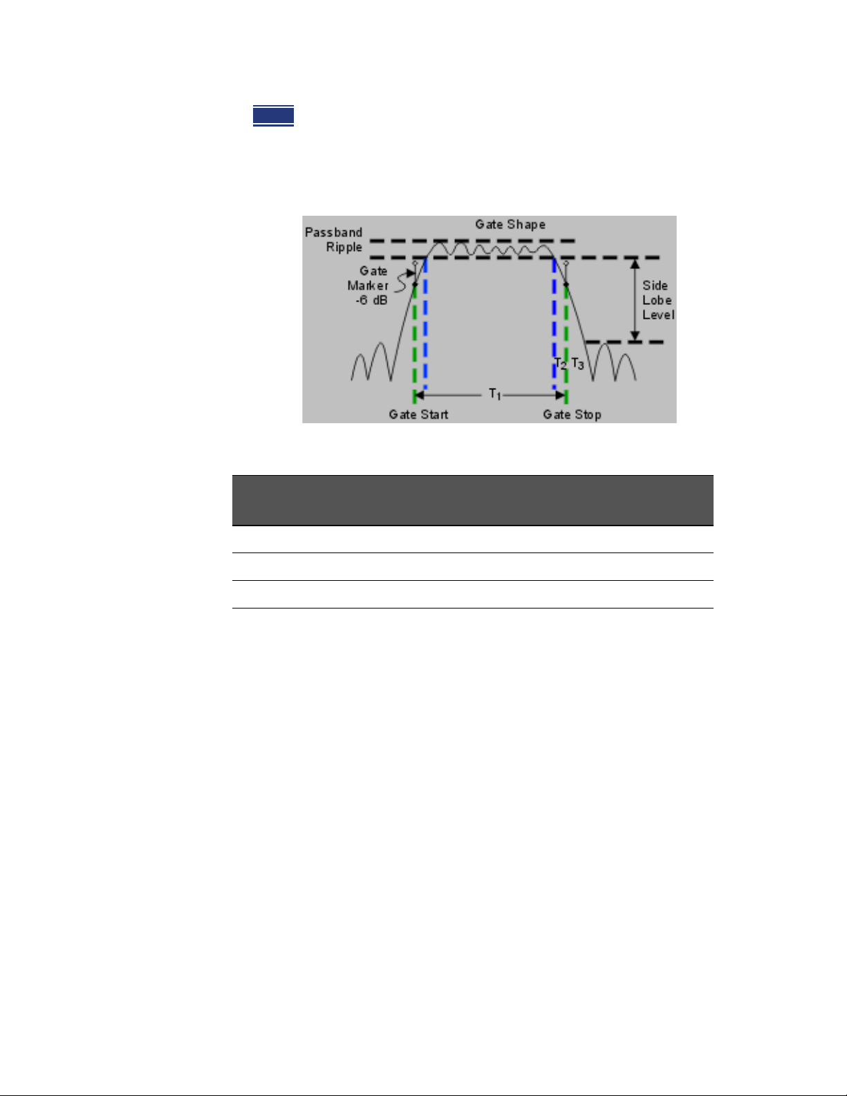
Time Domain – Option 010
Gating
— Notch REMOVES the responses within the Gating Start and Stop times.
Gating Shape
This setting defines the filter characteristics of the gate function. Choose from
Minimum, Normal, Wide, Maximum.
Time domain Gate Shape setting is shown in the graphic above.
Gate Shape Passband
Ripple
Minimum ±0.1 dB -48 dB 1.4/Freq Span 2.8/Freq Span
Normal ±0.1 dB -68 dB 2.8/Freq Span 5.6/Freq Span
Wide ±0.1 dB -57 dB 4.4/Freq Span 8.8/Freq Span
Maximum ±0.01 dB -70 dB 12.7/Freq Span 25.4/Freq Span
Sidelobe
Levels
Cutoff Time Minimum Gate
Span
Cutoff time is the time between the stop time (-6 dB on the filter skirt) and the
peak of the first sidelobe.
is the gate span, which is equal to the stop time minus the start time.
—T
1
—T
is the time between the edge of the passband and the 6 dB point,
2
representing the cutoff rate of the filter.
is the time between the 6 dB point and the edge of the gate stopband.
—T
3
For all filter shapes T
is equal to T3, and the filter is the same on both sides of
2
the center time.
Minimum gate span is twice the cutoff time. Each gate shape has a minimum
recommended gate span for proper operation. This is a consequence of the
finite cutoff rate of the gate. If you specify a gate span that is smaller than the
minimum span, the response will show the following effects:
— distorted gate shape that has no passband
—distorted shape
— incorrect indications of start and stop times
— may have increased sidelobe levels.
Keysight N9912-90001 User’s Guide 6- 11
Page 96

6-
Time Domain – Option 010
Gating
6- 12 Keysight N9912-90001 User’s Guide
Page 97

Keysight Handheld Analyzers
N9912A User’s Guide
7 Calibration for NA, CAT, and VVM Modes
Calibration removes the systematic errors that are associated with
measurements in NA, CAT, and VVM Modes. Key presses are identical in all of
these Modes.
In this Chapter
“Why and When to Calibrate” on page 7-2
“Definitions” on page 7-2
“Preset Calibration (also known as CalReady)” on
page 7-3
“QuickCal” on page 7-3
“O, S, L Cal” on page 7-5
“Normalize” on page 7-6
“Compatible Mode Calibrations” on page 7-8
“Compatible 1-port and 2-port Calibrations” on
page 7-8
“Save the Calibration” on page 7-9
“Verify a Calibration” on page 7-10
“Calibration Method Summary” on page 7-11
ECal and Waveguide Calibrations are NOT supported on the N9912A.
See Also
Learn How to Make 75 ohm Measurements at the FieldFox Supplemental
Online Help:
http://na.support.keysight.com/fieldfox/help/SupHelp/FieldFox.htm
7- 1
Page 98

7-
Calibration for NA, CAT, and VVM Modes
Why and When to Calibrate
Why and When to Calibrate
There are well-defined and understood systematic errors that are measured
and calculated during the calibration process. These errors are caused by
leakage signals inside the FieldFox, by the frequency response of the FieldFox
receivers, and by reflections inside the FieldFox that interact with the DUT.
After calibration, these errors are removed from subsequent measurements.
To maintain highest measurement accuracy, perform a new calibration when
any of the following changes occur:
— When any of the following measurement settings change: Frequency
Range, Power Level, and Resolution. Therefore, make these measurement
settings before calibrating. Increased Averaging and higher Resolution
cause slower sweeps and slower calibration times. Learn about
Interpolation and Questionable Accuracy in page 7-7.
— When the FieldFox temperature changes more than about 10°F (5°C). Learn
— When the connection to the DUT changes, requiring a different jumper
Definitions
DUT (Device Under Test) The cable, antenna, transmission line, or anything
else that is connected to the FieldFox that is to be measured.
Calibration Standards - OPEN, SHORT, LOAD, and THRU
— OPEN, SHORT, and LOAD are calibration standards. These are precision
more in “How to monitor the internal FieldFox temperature:” on page 2-4.
cable or adapter.
components that are used during calibration and to terminate a DUT during
some measurements. When an RF signal ‘hits’ these components, the
signals are reflected in a predictable manner.
— SHORT and OPEN standards both cause 100% of an RF signal to be
reflected. The difference between these two standards is what
happens to the phase of the reflected signal, which is beyond the
scope of this discussion. Although an OPEN standard is a precision
component, simply leaving nothing connected at the end of a cable
can be a reasonable substitute for an OPEN.
— A LOAD standard absorbs almost ALL of the incident signal and very
little signal is reflected back to the source.
Calibration Reference Plane is the point at which cal standards are connected
during a calibration. This can be either the FieldFox RF OUT connector, or at
the end of a jumper cable or adapter.
7- 2 Keysight N9912-90001 User’s Guide
Page 99
Calibration for NA, CAT, and VVM Modes
Why and When to Calibrate
Preset Calibration (also known as CalReady)
CalReady (Preset calibration) only applies to S11 and Return Loss
measurements. CalReady does not apply to S21 or Insertion Loss
measurements. Also, you can interpolate the S11 calibration, but you
cannot interpolate the S21 calibration or S21 normalization.
Every FieldFox is factory calibrated at the RF Out connector over the entire
frequency range of the FieldFox using a number of data points that allows
reasonable interpolation over the FieldFox frequency range.
This CalReady condition allows you to start using your FieldFox immediately if
you are measuring a device that is directly connected to the RF Out test port.
CalReady applies to the entire frequency range of the FieldFox. It can be used
to check the integrity of the jumper cable.
QuickCal
Cal ON
When measuring a DUT using a jumper cable or adapter - NOT a direct
connection to the RF Out connector – then a QuickCal or O,S,L Cal is
recommended.
Learn how to see when your factory CalReady calibration was performed in
“System Information” on page 22.
QuickCal is ideal for a quick and simple calibration of the measurement when
using a jumper cable or adapter to connect the DUT to the FieldFox test ports.
QuickCal corrects for phase shift, time delay, and loss of adapters or jumper
cables.
QuickCal does not require a specific Cal Kit and is a very simple calibration. If
the highest accuracy is required, a mechanical calibration with a high quality
calibration kit is recommended.
If the DUT has 3.5 mm-female or SMA-female connectors, QuickCal is NOT
recommended.
How to perform a QuickCal
is shown on the screen when powered ON or Preset.
Press Esc
— In CAT, NA, or VVM Mode, press Cal 5
— Then (if necessary) press Cal Type
—Press Start Cal
No Connection
— Disconnect the DUT from the FieldFox.
Keysight N9912-90001 User’s Guide 7- 3
at any time durign the QuickCal to stop the calibration.
.
to see [QuickCal].
.
Page 100
7-
Calibration for NA, CAT, and VVM Modes
Why and When to Calibrate
— If a jumper cable or adapter is required to connect the DUT to the FieldFox,
connect those components to the FieldFox RF Out connector NOW. The
effects of those components will be measured and removed during the
calibration, and only the effects of the DUT will be displayed in the
measurement results. These should be high-quality components!
— Do NOT connect anything at the cal reference plane where the DUT
connects.
—Then Press QuickCal
.
Optionally Connect Load(s)
— Connect a Load standard at the point where the DUT will be connected and
press Measure
under the following conditions:
— When a jumper cable has too much loss. If a ‘Cal Failed’ error
appears and you skipped the Load measurement, then perform the
Cal again but include measuring the Load.
— When your DUT has high return loss such as the reject band of a
filter. Then measuring the load improves accuracy. Even with the
optional Load, phase accuracy begins to degrade when the return
loss is greater than about 20dB.
7- 4 Keysight N9912-90001 User’s Guide
 Loading...