

Page 1

Keysight N9911X
Economical Waveguide
Calibration Components
User’s Guide
Page 2

Page 3

User’s Guide N9911-90002
Page 4

Notices
CAUTION
WARNING
© Keysight Technologies 2013, 2014
No part of this manual may be reproduced
in any form or by any means (including
electronic storage and retrieval or translation into a foreign language) without prior
agreement and written consent from Keysight Technologies as governed by United
States and international copyright laws.
Manual Part Number
N9911-90002
Edition
August 2014
Keysight Technologies
1400 Fountaingrove Parkway
Santa Rosa, CA 95403
Warranty
The material contained in this document is provided “as is,” and is subject to being changed, without notice,
in future editions. Further, to the maximum extent permitted by applicable
law, Keysight disclaims all warranties, either express or implied, with
regard to this manual and any information contained herein, including
but not limited to the implied warranties of merchantability and fitness for
a particular purpose. Keysight shall
not be liable for errors or for incidental or consequential damages in connection with the furnishing, use, or
performance of this document or of
any information contained herein.
Should Keysight and the user have a
separate written agreement with
warranty terms covering the material
in this document that conflict with
these terms, the warranty terms in
the separate agreement shall control.
Technology Licenses
The hardware and/or software described in
this document are furnished under a
license and may be used or copied only in
accordance with the terms of such license.
Restricted Rights Legend
52.227-19 (June 1987) or any equivalent
agency regulation or contract clause. Use,
duplication or disclosure of Software is
subject to Keysight Technologies’ standard
commercial license terms, and non-DOD
Departments and Agencies of the U.S. Government will receive no greater than
Restricted Rights as defined in FAR
52.227-19(c)(1-2) (June 1987). U.S. Government users will receive no greater than
Limited Rights as defined in FAR 52.227-14
(June 1987) or DFAR 252.227-7015 (b)(2)
(November 1995), as applicable in any
technical data.
Safety Notices
A CAUTION notice denotes a hazard. It calls attention to an operating procedure, practice, or the like
that, if not correctly performed or
adhered to, could result in damage
to the product or loss of important
data. Do not proceed beyond a
CAUTION notice until the indicated
conditions are fully understood and
met.
A WARNING notice denotes a
hazard. It calls attention to an
operating procedure, practice, or
the like that, if not correctly performed or adhered to, could result
in personal injury or death. Do not
proceed beyond a WARNING
notice until the indicated conditions are fully understood and met.
If software is for use in the performance of
a U.S. Government prime contract or subcontract, Software is delivered and
licensed as “Commercial computer software” as defined in DFAR 252.227-7014
(June 1995), or as a “commercial item” as
defined in FAR 2.101(a) or as “Restricted
computer software” as defined in FAR
Page 5

Printing Copies of Documentation from the
Web
To print copies of documentation from the Web, download the PDF file
from the Keysight web site:
•Go to http://www.keysight.com.
• Enter the product model number (Ex: N9911X) in the Search bar.
• Click Search.
• Click the Manuals hyperlink.
• Click the hyperlink title for the document you want to print - this
downloads the PDF
• Print the document after the PDF has fully downloaded.
User’s Guide N9911-90002
Page 6

User’s Guide N9911-90002
Page 7

Contents
1. General Information
Overview . . . . . . . . . . . . . . . . . . . . . . . . . . . . . . . . . . . . . . . . . . . . . . . . . . . . . . . . . . . . . . . . . . . . . . . . . . . . . . . . . . . . . . . 1-2
Recording the Components Serial Numbers . . . . . . . . . . . . . . . . . . . . . . . . . . . . . . . . . . . . . . . . . . . . . . . . . . . . . . . . . 1-3
Preventive Maintenance. . . . . . . . . . . . . . . . . . . . . . . . . . . . . . . . . . . . . . . . . . . . . . . . . . . . . . . . . . . . . . . . . . . . . . . . . .1-7
When to Calibrate the Analyzer. . . . . . . . . . . . . . . . . . . . . . . . . . . . . . . . . . . . . . . . . . . . . . . . . . . . . . . . . . . . . . . . . . . .1-7
How to Calibrate the Analyzer . . . . . . . . . . . . . . . . . . . . . . . . . . . . . . . . . . . . . . . . . . . . . . . . . . . . . . . . . . . . . . . . . . . . . 1-7
2. Specifications
Environmental Requirements. . . . . . . . . . . . . . . . . . . . . . . . . . . . . . . . . . . . . . . . . . . . . . . . . . . . . . . . . . . . . . . . . . . . . . 2-2
Temperature—What to Watch Out For . . . . . . . . . . . . . . . . . . . . . . . . . . . . . . . . . . . . . . . . . . . . . . . . . . . . . . . . . . .2-2
Typical VSWR Values. . . . . . . . . . . . . . . . . . . . . . . . . . . . . . . . . . . . . . . . . . . . . . . . . . . . . . . . . . . . . . . . . . . . . . . . . . . . . 2-3
Instrument Interface Specifications . . . . . . . . . . . . . . . . . . . . . . . . . . . . . . . . . . . . . . . . . . . . . . . . . . . . . . . . . . . . . . . .2-4
Dimension Specifications. . . . . . . . . . . . . . . . . . . . . . . . . . . . . . . . . . . . . . . . . . . . . . . . . . . . . . . . . . . . . . . . . . . . . . . . .2-5
3. Use, Maintenance, and Care of the Components
Electrostatic Discharge. . . . . . . . . . . . . . . . . . . . . . . . . . . . . . . . . . . . . . . . . . . . . . . . . . . . . . . . . . . . . . . . . . . . . . . . . . . 3-2
Visual Inspection . . . . . . . . . . . . . . . . . . . . . . . . . . . . . . . . . . . . . . . . . . . . . . . . . . . . . . . . . . . . . . . . . . . . . . . . . . . . . . . . 3-3
Cleaning the Mating Plane Surfaces . . . . . . . . . . . . . . . . . . . . . . . . . . . . . . . . . . . . . . . . . . . . . . . . . . . . . . . . . . . . . . . 3-4
Connections . . . . . . . . . . . . . . . . . . . . . . . . . . . . . . . . . . . . . . . . . . . . . . . . . . . . . . . . . . . . . . . . . . . . . . . . . . . . . . . . . . . . 3-5
Aligning Two Precision Flanges. . . . . . . . . . . . . . . . . . . . . . . . . . . . . . . . . . . . . . . . . . . . . . . . . . . . . . . . . . . . . . . . . .3-5
Tightening a Flange Connection . . . . . . . . . . . . . . . . . . . . . . . . . . . . . . . . . . . . . . . . . . . . . . . . . . . . . . . . . . . . . . . . . 3-7
Inspecting a Flange Connection . . . . . . . . . . . . . . . . . . . . . . . . . . . . . . . . . . . . . . . . . . . . . . . . . . . . . . . . . . . . . . . . . 3-7
Connecting a Termination to a Waveguide-to-Coax Adapter . . . . . . . . . . . . . . . . . . . . . . . . . . . . . . . . . . . . . . . . .3-8
Connecting an Offset Shim Between a Flush Short and Waveguide-to-Coax Adapter . . . . . . . . . . . . . . . . . . . 3-8
Connecting a Flush Short to a Waveguide-to-Coax Adapter . . . . . . . . . . . . . . . . . . . . . . . . . . . . . . . . . . . . . . . . . 3-9
Handling and Storage . . . . . . . . . . . . . . . . . . . . . . . . . . . . . . . . . . . . . . . . . . . . . . . . . . . . . . . . . . . . . . . . . . . . . . . . . . . 3-10
4. Troubleshooting
Troubleshooting Process . . . . . . . . . . . . . . . . . . . . . . . . . . . . . . . . . . . . . . . . . . . . . . . . . . . . . . . . . . . . . . . . . . . . . . . . . 4-2
Where to Look for More Information . . . . . . . . . . . . . . . . . . . . . . . . . . . . . . . . . . . . . . . . . . . . . . . . . . . . . . . . . . . . . . . 4-3
Returning a Component to Keysight . . . . . . . . . . . . . . . . . . . . . . . . . . . . . . . . . . . . . . . . . . . . . . . . . . . . . . . . . . . . . . . . 4-3
Contacting Keysight . . . . . . . . . . . . . . . . . . . . . . . . . . . . . . . . . . . . . . . . . . . . . . . . . . . . . . . . . . . . . . . . . . . . . . . . . . . . . 4-4
5. Component Dimensions
Flange Dimensions . . . . . . . . . . . . . . . . . . . . . . . . . . . . . . . . . . . . . . . . . . . . . . . . . . . . . . . . . . . . . . . . . . . . . . . . . . . . . . 5-5
Waveguide-to-Coax Adapter Dimensions . . . . . . . . . . . . . . . . . . . . . . . . . . . . . . . . . . . . . . . . . . . . . . . . . . . . . . . . . .5-10
Termination Dimensions . . . . . . . . . . . . . . . . . . . . . . . . . . . . . . . . . . . . . . . . . . . . . . . . . . . . . . . . . . . . . . . . . . . . . . . . . 5-18
Offset Shim Dimensions . . . . . . . . . . . . . . . . . . . . . . . . . . . . . . . . . . . . . . . . . . . . . . . . . . . . . . . . . . . . . . . . . . . . . . . . .5-26
Flush Short Dimensions . . . . . . . . . . . . . . . . . . . . . . . . . . . . . . . . . . . . . . . . . . . . . . . . . . . . . . . . . . . . . . . . . . . . . . . . . 5-34
User’s Guide N9911-90002
Page 8

Contents
User’s Guide N9911-90002
Page 9

1 General Information
User’s Guide N9911-90002 1- 1
Page 10

General Information
Overview
Overview
N9911X Economical Waveguide Calibration Components are used to calibrate FieldFox analyzers. With the
calibration data properly loaded in the analyzer and a measurement calibration completed, systematic errors
are minimized. For information on components available to purchase, refer to the online document Keysight
N9911X Economical Waveguide Calibration Components Configuration Guide (part number N9911-90003).
1- 2 User’s Guide N9911-90002
Page 11

General Information
Recording the Components Serial Numbers
Recording the Components Serial Numbers
The N9911X Economical Waveguide Components are individually serialized (serial numbers are labeled onto
the body of each component). Record these serial numbers in the appropriate table. Recording the serial
numbers will prevent confusion with similar components.
The N9911X calibration components are manufactured by Flann Microwave. Each component is imprinted
with a Flann logo, part ID number, and serial number. To determine the Keysight option number for a
component, use the cross-references in the following tables.
Table 1-1 Serial Number Record, Waveguide Designators C-Band/WR137/WG14, 5.38 – 8.18 GHz
Description Component
Serial Number
Calibration Components – Metric
Adapter 1, waveguide to type-N (male) coax
Adapter 2, waveguide to type-N (male) coax
Termination
Flush short
¼ wavelength offset shim
Calibration Components – English (Imperial)
Adapter 1, waveguide to type-N (male) coax
Adapter 2, waveguide to type-N (male) coax
Termination
Flush short
¼ wavelength offset shim
Keysight
Option Number
N9911X
N9911X
N9911X
N9911X
N9911X
N9911X
N9911X
N9911X
N9911X
N9911X
–110
–110
–111
–112
–113
–115
–115
–116
–117
–118
Flann
Part ID Number
14091–NM70–6332
14091–NM70–6332
14045–6333
14191–6334
14491–02–6335
14091–NM70–6136
14091–NM70–6136
14045–3703
14191–704
14491–02–3483
User’s Guide N9911-90002 1-3
Page 12

General Information
Recording the Components Serial Numbers
Table 1-2 Serial Number Record, Waveguide Designator X-Band/WR90/WG16, 8.2 – 12.5 GHz
Description Component
Serial Number
Calibration Components – Metric
Adapter 1, waveguide to type-N (male) coax
Adapter 2, waveguide to type-N (male) coax
Termination
Flush short
¼ wavelength offset shim
Calibration Components – English (Imperial)
Adapter 1, waveguide to type-N (male) coax
Adapter 2, waveguide to type-N (male) coax
Termination
Flush short
¼ wavelength offset shim
Keysight
Option Number
N9911X
N9911X
N9911X
N9911X
N9911X
N9911X
N9911X
N9911X
N9911X
N9911X
–210
–210
–211
–212
–213
–215
–215
–216
–217
–218
Flann
Part ID Number
16091–NM70–6336
16091–NM70–6336
16045–6337
16191–6338
16491–02–6339
16091–NM70–6141
16091–NM70–6141
16045–5509
16191–2547
16491–02–2401
1- 4 User’s Guide N9911-90002
Page 13

General Information
Recording the Components Serial Numbers
Table 1-3 Serial Number Record, Waveguide Designator Ku-Band/WR62/WG18, 11.9 – 18 GHz
Description Component
Serial Number
Calibration Components – Metric
Adapter 1, waveguide to type-N (male) coax
Adapter 2, waveguide to type-N (male) coax
Termination
Flush short
¼ wavelength offset shim
Calibration Components – English (Imperial)
Adapter 1, waveguide to type-N (male) coax
Adapter 2, waveguide to type-N (male) coax
Termination
Flush short
¼ wavelength offset shim
Keysight
Option Number
N9911X
N9911X
N9911X
N9911X
N9911X
N9911X
N9911X
N9911X
N9911X
N9911X
–310
–310
–311
–312
–313
–315
–315
–316
–317
–318
Flann
Part ID Number
18091–NM–6340
18091–NM–6340
18045–6341
18191–6342
18491–02–6343
18091–NM–6024
18091–NM–6024
18045–2546
18191–4127
18491–02–4095
User’s Guide N9911-90002 1-5
Page 14

General Information
Recording the Components Serial Numbers
Table 1-4 Serial Number Record, Waveguide Designator K-Band/WR42/WG20, 17.6 – 26.7 GHz
Description Component
Serial Number
Calibration Components – Metric
Adapter 1, waveguide to 3.5 mm (male) coax
Adapter 2, waveguide to 3.5 mm (male) coax
Termination
Flush short
¼ wavelength offset shim
Calibration Components – English (Imperial)
Adapter 1, waveguide to 3.5 mm (male) coax
Adapter 2, waveguide to 3.5 mm (male) coax
Termination
Flush short
¼ wavelength offset shim
Keysight
Option Number
N9911X
N9911X
N9911X
N9911X
N9911X
N9911X
N9911X
N9911X
N9911X
N9911X
–310
–310
–311
–312
–313
–315
–315
–316
–317
–318
Flann
Part ID Number
20091–JM–2371
20091–JM–2371
20045–2376
20191–6349
20491–02–6351
20091–JM–2372
20091–JM–2372
20045–5174
20191–6348
20491–02–6350
1- 6 User’s Guide N9911-90002
Page 15

General Information
Preventive Maintenance
Preventive Maintenance
The best techniques for maintaining the integrity of the components include:
• routine visual inspection
• routine cleaning
• proper connection techniques
All of these are described in Chapter 3. Failure to detect and remove dirt or metallic particles on a mating
plane surface can degrade repeatability and accuracy and can damage any component mated to it. Improper
connections resulting from poor connection techniques, can also damage these components.
When to Calibrate the Analyzer
An analyzer calibration remains valid as long as the changes in the systematic error are insignificant. This
means that changes to the uncorrected leakages (directivity and isolation), mismatches (source match and
load match), and frequency response of the system are small (<10%) relative to accuracy specifications.
Change in the environment (especially temperature) between calibration and measurement is the major
cause in calibration accuracy degradation. The major effect is a change in the physical length of external and
internal cables. Other important causes are dirty and damaged test port connectors and calibration
standards. If the connectors become dirty or damaged, measurement repeatability and accuracy is affected.
Fortunately, it is relatively easy to evaluate the general validity of the calibration. To test repeatability,
remeasure one of the calibration standards. If you can not obtain repeatable measurements from your
calibration standards, maintenance needs to be performed on the test port connectors, cables and
calibration standards. Also, maintain at least one sample of the device under test or some known device as
your reference device.
How to Calibrate the Analyzer
Your analyzer’s calibration user interface prompts you through each step in a 1-port or a 2-port calibration
procedure. For detailed information on using your analyzer, refer to the appropriate user guide. See “Where
to Look for More Information” on page 4-3.
User’s Guide N9911-90002 1-7
Page 16

General Information
Preventive Maintenance
1- 8 User’s Guide N9911-90002
Page 17

2 Specifications
User’s Guide N9911-90002 2- 1
Page 18

Specifications
Environmental Requirements
Environmental Requirements
Table 2-1 Environmental Requirements
Parameter Limits
Temperature
Operating
Storage -20 °C to +70 °C
1. The temperature range over which the calibration components maintain performance to their specifications.
1
+4 °C to +40 °C
Temperature—What to Watch Out For
Changes in temperature can affect electrical characteristics. Therefore, the operating temperature is a
critical factor in performance. During a measurement calibration, the temperature of the calibration
components must be stable and within the range shown in
Tab le 2- 1.
IMPORTANT Avoid unnecessary handling of the components during calibration because your fingers act
as a heat source and may increase the temperature of the component.
2- 2 User’s Guide N9911-90002
Page 19

Specifications
Typical VSWR Values
Typical VSWR Values
Tab le 2- 2 and Tab le 2 - 3 list the typical VSWR values for the N9911X terminations and waveguide-to-coax
adapters.
Tab le 2- 2 Ty p i c a l VS WR Va l u e s f or Ter mi n a t i o ns
Keysight
Option Number
for Termination
N9911X–111
N9911X–116 English
N9911X–211
N9911X–216 English
N9911X–311
N9911X–316 English
N9911X–411
N9911X–416 English
Waveguide Band Designator Thread
Ty p e
Metric
C-Band, WR137, WG14
(Imperial)
Metric
X-Band, WR90, WG16
(Imperial)
Metric
Ku-Band, WR62, WG18
(Imperial)
Metric
K-Band, WR42, WG20
(Imperial)
Frequency VSWR,
Maximum
1.10
5.38 to 8.18 GHz
8.2 to 12.5 GHz 1.02
11.9 to 18 GHz 1.02
17.6 to 26.7GHz 1.03
1.02
Table 2-3 Typical VSWR Values for Waveguide-to-Coax Adapters
Keysight
Option Number
for Adapter
Waveguide Band Designator Thread
Ty p e
Frequency VSWR,
Maximum
N9911X–110
N9911X–115 English
N9911X–210
N9911X–215 English
N9911X–310
N9911X–315 English
N9911X–410
N9911X–415 English
User’s Guide N9911-90002 2-3
C-Band, WR137, WG14
X-Band, WR90, WG16
Ku-Band, WR62, WG18
K-Band, WR42, WG20
Metric
5.38 to 8.18 GHz 1.10
(Imperial)
Metric
8.2 to 12.5 GHz 1.10
(Imperial)
Metric
11.9 to 18 GHz 1.10
(Imperial)
Metric
17.6 to 26.7GHz 1.20
(Imperial)
Page 20

Specifications
Instrument Interface Specifications
Instrument Interface Specifications
Table 2-4 N9911X Instrument Interface Specifications
Waveguide
Band
Designator
C-Band/
WR137/
WG14
X-Band/
WR90/
WG16
Ku-Band/
WR62/
WG18
K-Band/
WR42/
WG20
Thread Type Compatible Flange Type
Metric Flange (UAR 70, PAR 70, CAR 70, UDR 70, RDR 70, PDR 70)
English
(Imperial)
Metric Flange (UBR 100, PBR 100, CBR 100, UDR 100, PDR 100, RDR 100)
English
(Imperial)
Metric Flange (UBR 140, PBR 140, CBR 140, UDR 140, PDR 140, RDR 140)
English
(Imperial)
Metric Flange (UBR 220, PBR 220, CBR 220, UDR 220, PDR 220, RDR 220)
English
(Imperial)
Flange (UG-441/U, UG-344/U, UG-343B/U, UG-440B/U, UG-1733/U, UG-1732/U,
UG-1356/U, UG-1357/U, CPR 137F, CPR 137G)
Flange (UG-39/U, UG-135/U, M3922/53-009, M3922/53-010, M3922/53-015,
M3922/53-016, UG-40B/U, UG-136B/U, M3922/59-013, M3922/59-014,
UG-1736/U, UG-1737/U, UG-1360/U, UG-1361/U, CPR 90F, CPR 90G)
Flange (UG-419A/U, UG-1665/U, M3922/53-011, M3922/53-012, M3922/53-017,
M3922/53-018, UG-541A/U, UG-1666/U)
Flange (UG-595/U, UG-597/U, UG596A/U, UG-598A/U, M3922/70-027,
M3922/70-028)
2- 4 User’s Guide N9911-90002
Page 21

Specifications
Dimension Specifications
Dimension Specifications
Table 2-5 N9911X Dimension Specifications
Component Parameter WR137 WR90 WR62 WR42
Adapter,
waveguide-to-coax
Termination Waveguide aperture
Flush short Shorting face flatness 25 um 25 um 25 um 25 um
1/4 wavelength offset
shim
Waveguide aperture
tolerance
tolerance
Waveguide aperture
tolerance
46 um MAX 25 um MAX 23 um MAX 20 um MAX
46 um MAX 25 um MAX 23 um MAX 20 um MAX
46 um MAX,
14.711 mm
+/– 45 um
25 um MAX,
9.63 mm
+/– 35 um
23 um MAX,
6.668 mm
+/– 30 um
20 um MAX,
4.501 mm
+/– 25 um
NOTE Refer to the Appendix for graphics showing the component dimensions.
User’s Guide N9911-90002 2-5
Page 22

Specifications
Dimension Specifications
2- 6 User’s Guide N9911-90002
Page 23

3 Use, Maintenance, and Care of the Components
User’s Guide N9911-90002 3- 1
Page 24

Use, Maintenance, and Care of the Components
Electrostatic Discharge
Electrostatic Discharge
Protection against electrostatic discharge (ESD) is essential while connecting, inspecting, or cleaning
connectors attached to a static-sensitive circuit (such as those found in test sets).
Static electricity can build up on your body and can easily damage sensitive internal circuit elements when
discharged. Static discharges too small to be felt can cause permanent damage. Devices such as calibration
components and devices under test (DUT), can also carry an electrostatic charge. To prevent damage to the
test set, components, and devices:
• always wear a grounded wrist strap having a 1 MW resistor in series with it when handling components
and devices or when making connections to the test set.
• always use a grounded antistatic mat in front of your test equipment.
• always wear a heel strap when working in an area with a conductive floor. If you are uncertain about the
conductivity of your floor, wear a heel strap.
• always ground yourself before you clean, inspect, or make a connection to a static-sensitive device or
test port. You can, for example, grasp the grounded outer shell of the test port or cable connector briefly.
• always ground the center conductor of a test cable before making a connection to the analyzer test port
or other static-sensitive device. This can be done as follows:
1. Connect a short to one end of the cable to short the center conductor to the outer conductor.
2. While wearing a grounded wrist strap, grasp the outer shell of the cable connector.
3. Connect the other end of the cable to the test port.
• Remove the short from the cable.
Figure 3-1 shows a typical ESD protection setup using a grounded mat and wrist strap.
Figure 3-1 ESD Protection Setup
3- 2 User’s Guide N9911-90002
Page 25

Use, Maintenance, and Care of the Components
Visual Inspection
Visual Inspection
Visual inspection and, if necessary, cleaning should be done every time a connection is made. Inspect
mating surfaces for dirt, dust, foreign particles, or scratches, which can degrade component performance. A
damaged mating surface can damage any good surface connected to it. If necessary, clean all mating
surfaces.
Magnification is helpful when inspecting mating surfaces, but it is not required and may actually be
misleading. Defects and damage that cannot be seen without magnification generally have no effect on
electrical or mechanical performance. Magnification is of great use in analyzing the nature and cause of
damage and in cleaning mating surfaces, but it is not required for inspection.
User’s Guide N9911-90002 3-3
Page 26

Use, Maintenance, and Care of the Components
Cleaning the Mating Plane Surfaces
Cleaning the Mating Plane Surfaces
1. Use Compressed Air or Nitrogen
WARNING Always use protective eyewear when using compressed air or nitrogen.
Use compressed air (or nitrogen) to loosen particles on the mating plane surfaces. Clean air cannot
damage a component or leave particles or residues behind.
You can use any source of clean, dry, low-pressure compressed air or nitrogen that has an effective
oil-vapor filter and liquid condensation trap placed just before the outlet hose.
Ground the hose nozzle to prevent electrostatic discharge, and set the air pressure to less than 414 kPa
(60 psi) to control the velocity of the air stream. High-velocity streams of compressed air can cause
electrostatic effects when directed into a component. These electrostatic effects can damage the
component. Refer to “Electrostatic Discharge” earlier in this chapter for additional information.
WARNING Keep isopropyl alcohol away from heat, sparks, and flame. Store in a tightly closed
container. It is extremely flammable. In case of fire, use alcohol foam, dry chemical, or
carbon dioxide; water may be ineffective.
Use isopropyl alcohol with adequate ventilation and avoid contact with eyes, skin, and
clothing. It causes skin irritation, may cause eye damage, and is harmful if swallowed or
inhaled. It may be harmful if absorbed through the skin. Wash thoroughly after handling.
In case of spill, soak up with sand or earth. Flush spill area with water.
Dispose of isopropyl alcohol in accordance with all applicable federal, state, and local
environmental regulations.
2. Clean the Mating Plane Surfaces
a. Apply a small amount of isopropyl alcohol to a lint-free cleaning swab.
b. Clean the mating plane surfaces.
c. Let the alcohol evaporate, then blow the mating plane surface dry with a gentle stream of clean,
low-pressure compressed air or nitrogen. Always completely dry a component before you reassemble
or use it.
3. Inspect
a. Inspect the mating plane surface to make sure that no particles or residue remain. “Visual
Inspection” on page 3-3.
3- 4 User’s Guide N9911-90002
Page 27

Use, Maintenance, and Care of the Components
Connections
Connections
Good connections require a skilled operator. Slight errors in operator technique can have a significant effect
on measurements and measurement uncertainties. The most common cause of measurement error is poor
connections.
The following procedures illustrate how to make good connections.
IMPORTANT Unlike threaded components, the WR-90, WR-62, WR-42 waveguide mating planes are
flanges that you must carefully screw together. Always connect waveguide in the same
flange orientation. For example, use the label as a reference and always connect
components with the labels facing the same direction.
Aligning Two Precision Flanges
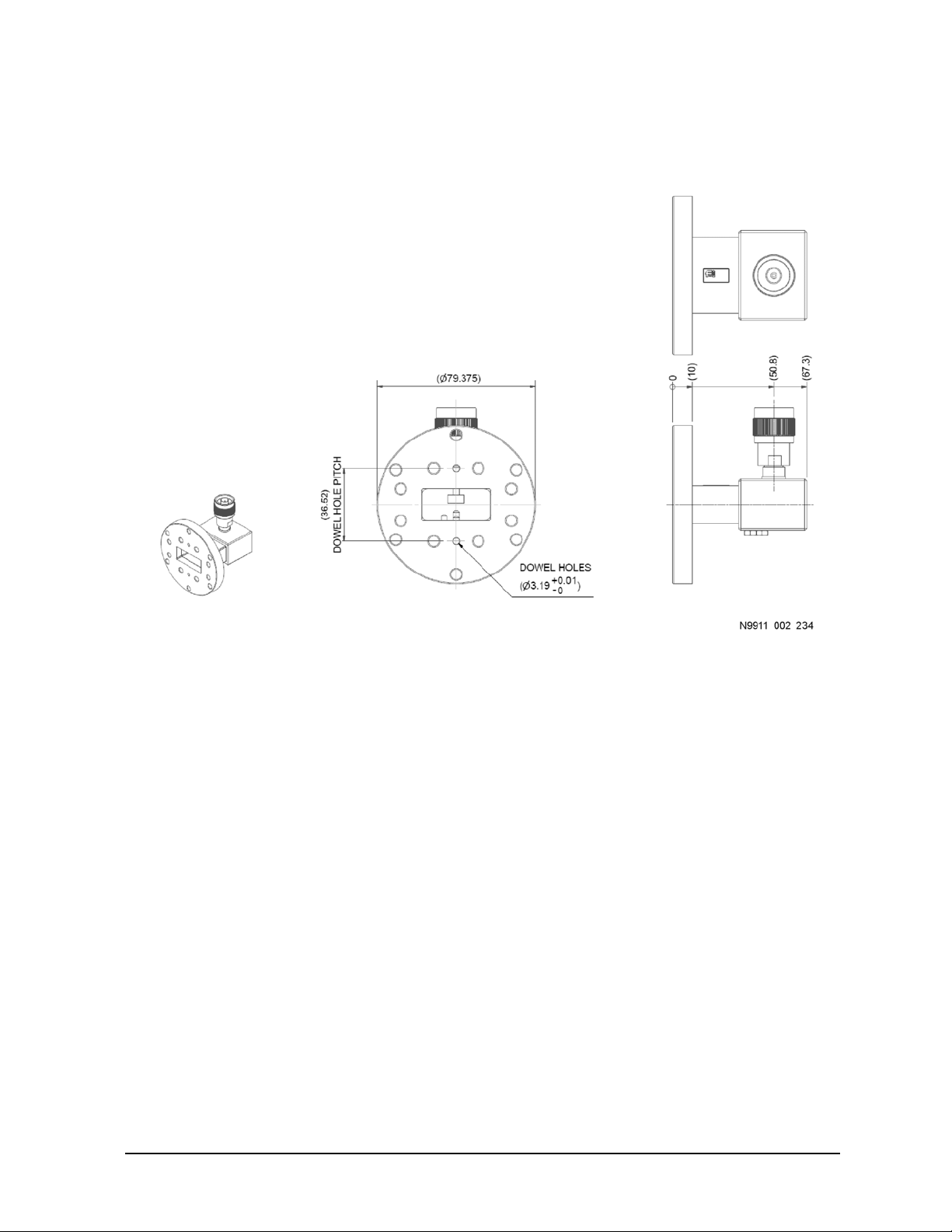
A precision flange has two precision alignment holes, as shown in Figure 3-2. A non-precision flange has
only screw holes.
Figure 3-2 Precision Alignment Holes
User’s Guide N9911-90002 3-5
Page 28
Use, Maintenance, and Care of the Components
Connections
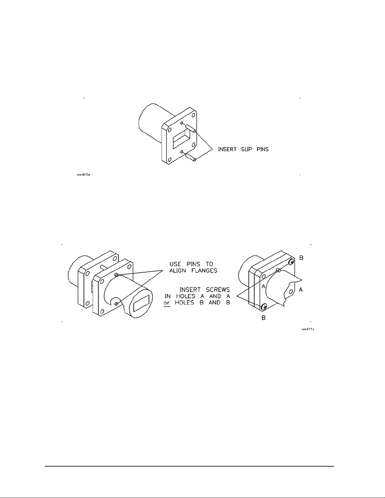
1. Place the slip pins in the top and bottom holes of one flange, as shown in Figure 3-3.
Figure 3-3 Inserting Slip Pins
2. Using the pins as guides for the adapter, offset shim, and waveguide-to-coax adapter, carefully align the
flanges and insert two screws in the diagonal corner holes, as shown in Figure 3-4.
Figure 3-4 Aligning Flanges
3. Place a lock washer and nut on each screw, and finger tighten.
4. Insert the remaining two screws.
5. Place a lock washer and nut on each screw, and finger tighten.
6. Remove the slip pins.
7. Go to “Tightening a Flange Connection” on page 3-7.
3- 6 User’s Guide N9911-90002
Page 29

Use, Maintenance, and Care of the Components
Connections
Tightening a Flange Connection
NOTE The best connection has symmetrical pressure applied as you gradually tighten the screws.
1. In an “X” pattern (for equal compression), tighten all four screws using a hex ball driver. Do not
over-tighten. See Figure 3-5.
2. Visually inspect the connection. Refer to the following section “Inspecting a Flange Connection.”
Figure 3-5 “X” Screw Pattern
Inspecting a Flange Connection
Inspect the flange connection as follows:
1. Place an electric light or white paper behind the connection.
2. Check the flange matings for any gap. A good connection has no gaps between the connected
waveguide flanges, and the waveguide walls are flush. There is no step or offset.
3. Ensure that all four screws are equally tight.
User’s Guide N9911-90002 3-7
Page 30

Use, Maintenance, and Care of the Components
Connections
Connecting a Termination to a Waveguide-to-Coax Adapter
Figure 3-6 Termination and Adapter
Connecting an Offset Shim Between a Flush Short and Waveguide-to-Coax Adapter
Create an offset short by connecting the offset shim between the short and the appropriate adapter, as
shown in Figure 3-7.
Figure 3-7 Shim, Flush Short, and Adapter (Creates an Offset Short)
3- 8 User’s Guide N9911-90002
Page 31

Use, Maintenance, and Care of the Components
Connecting a Flush Short to a Waveguide-to-Coax Adapter
Figure 3-8 Flush Short and Adapter
Connections
User’s Guide N9911-90002 3-9
Page 32

Use, Maintenance, and Care of the Components
Handling and Storage
Handling and Storage
• Install the protective end caps and store the calibration components when not in use.
• Never store components loose in a box, or in a desk or bench drawer. This is the most common cause of
component damage during storage.
• Keep components clean.
• Do not touch mating plane surfaces. Natural skin oils and microscopic particles of dirt are easily
transferred to a component and are very difficult to remove.
• Do not set components contact-end down on a hard surface. The plating and the mating plane surfaces
can be damaged if the interface comes in contact with any hard surface.
3- 10 User’s Guide N9911-90002
Page 33

4 Troubleshooting
User’s Guide N9911-90002 4- 1
Page 34

Troubleshooting
Troubleshooting Process
Troubleshooting Process
If you suspect a bad calibration, or if your analyzer does not pass performance verification, follow the steps
in Figure 4-1
Figure 4-1 Troubleshooting Flowchart
4- 2 User’s Guide N9911-90002
Page 35

Tr ou b le s h oo t in g
Where to Look for More Information
Where to Look for More Information
This manual contains limited information about analyzer system operation. For detailed information on using
a FieldFox analyzer, refer to the appropriate user guide.
To view an online FieldFox user guide, use the following steps:
1. Go to www.keysight.com.
2. Enter your FieldFox model number (Ex: N9928A) in the Search box and click Search.
3. Click Manuals.
4. Click the title/hyperlink for the document PDF you want to view.
If you need additional information, see “Contacting Keysight” on page 4-4.
Returning a Component to Keysight
If an N9911X component requires service, contact Keysight Technologies for information on where to send it
- see “Contacting Keysight” on page 4-4. Please provide the following information:
• your company name and address
• a technical contact person within your company, and the person's complete telephone number
• the Keysight option number, Flann part ID number, and serial number of the component (refer to
“Recording the Components Serial Numbers” on page 1-3)
• the type of service required
•a detailed description of the problem and how the component was being used when the problem
occurred
NOTE When returning a component to Keysight, install the protective end caps on the component.
User’s Guide N9911-90002 4-3
Page 36

Troubleshooting
Contacting Keysight
Contacting Keysight
Assistance with test and measurement needs and information on finding a local Keysight office are
available on the Web at:
www.keysight.com/find/assist
If you do not have access to the Internet, please contact your Keysight field engineer.
NOTE In any correspondence or telephone conversation, refer to the Keysight product by its model
number and full serial number. With this information, the Keysight representative can
determine whether your product is still within its warranty period.
4- 4 User’s Guide N9911-90002
Page 37

5 Component Dimensions
User’s Guide N9911-90002 5- 1
Page 38

Component Dimensions
Table 5-1 List of Figures
Figure Title and Location
“Flange, Waveguide Designators C-Band/WR137/WG14, Metric” on page 5-5
“Flange, Waveguide Designators C-Band/WR137/WG14, English (Imperial)” on
page 5-6
“Flange, Waveguide Designators X-Band/WR90/WG16, Metric” on page 5-6
“Flange, Waveguide Designators X-Band/WR90/WG16, English (Imperial)” on
page 5-7
“Flange, Waveguide Designators Ku-Band/WR62/WG18, Metric” on page 5-7
“Flange, Waveguide Designators Ku-Band/WR62/WG18, English (Imperial)” on
page 5-8
“Flange, Waveguide Designators K-Band/WR42/WG20, Metric” on page 5-8
“Flange, Waveguide Designators K-Band/WR42/WG20, English (Imperial)” on
page 5-9
“Adapter, Waveguide Designators C-Band/WR137/WG14, Metric, Keysight Part
Number N9911X-110” on page 5-10
“Adapter, Waveguide Designators C-Band/WR137/WG14, English (Imperial),
Keysight Part Number N9911X-115” on page 5-11
“Adapter, Waveguide Designators X-Band/WR90/WG16, Metric, Keysight Part
Number N9911X-210” on page 5-12
“Adapter, Waveguide Designators X-Band/WR90/WG16, English (Imperial),
Keysight Part Number N9911X-215” on page 5-13
“Adapter, Waveguide Designators Ku-Band/WR62/WG18, Metric, Keysight Part
Number N9911X-310” on page 5-14
“Adapter, Waveguide Designators Ku-Band/WR62/WG18, English (Imperial),
Keysight Part Number N9911X-315” on page 5-15
“Adapter, Waveguide Designators K-Band/WR42/WG20, Metric, Keysight Part
Number N9911X-410” on page 5-16
“Adapter, Waveguide Designators K-Band/WR42/WG20, English (Imperial),
Keysight Part Number N9911X-415” on page 5-17
“Termination, Waveguide Designators C-Band/WR137/WG14, Metric, Keysight
Part Number N9911X-111” on page 5-18
5- 2 User’s Guide N9911-90002
Page 39

Component Dimensions
Table 5-1 List of Figures
Figure Title and Location
“Termination, Waveguide Designators C-Band/WR137/WG14, English (Imperial),
Keysight Part Number N9911X-116” on page 5-19
“Termination, Waveguide Designators X-Band/WR90/WG16, Metric, Keysight Part
Number N9911X-211” on page 5-20
“Termination, Waveguide Designators X-Band/WR90/WG16, English (Imperial),
Keysight Part Number N9911X-216” on page 5-21
“Termination, Waveguide Designators Ku-Band/WR62/WG18, Metric, Keysight
Part Number N9911X-311” on page 5-22
“Termination, Waveguide Designators Ku-Band/WR62/WG18, English (Imperial),
Keysight Part Number N9911X-316” on page 5-23
“Termination, Waveguide Designators K-Band/WR42/WG20, Metric, Keysight Part
Number N9911X-411” on page 5-24
“Termination, Waveguide Designators K-Band/WR42/WG20, English (Imperial),
Keysight Part Number N9911X-416” on page 5-25
“Offset Shim, Waveguide Designators C-Band/WR137/WG14, Metric, Keysight
Part Number N9911X-113” on page 5-26
“Offset Shim, Waveguide Designators C-Band/WR137/WG14, English (Imperial),
Keysight Part Number N9911X-118” on page 5-27
“Offset Shim, Waveguide Designators X-Band/WR90/WG16, Metric, Keysight Part
Number N9911X-213” on page 5-28
“Offset Shim, Waveguide Designators X-Band/WR90/WG16, English (Imperial),
Keysight Part Number N9911X-218” on page 5-29
“Offset Shim, Waveguide Designators Ku-Band/WR62/WG18, Metric, Keysight
Part Number N9911X-313” on page 5-30
“Offset Shim, Waveguide Designators Ku-Band/WR62/WG18, English (Imperial),
Keysight Part Number N9911X-318” on page 5-31
“Offset Shim, Waveguide Designators K-Band/WR42/WG20, Metric, Keysight Part
Number N9911X-413” on page 5-32
“Offset Shim, Waveguide Designators K-Band/WR42/WG20, English (Imperial),
Keysight Part Number N9911X-418” on page 5-33
“Flush Short, Waveguide Designators C-Band/WR137/WG14, Metric, Keysight
Part Number N9911X-112” on page 5-34
User’s Guide N9911-90002 5-3
Page 40

Component Dimensions
Table 5-1 List of Figures
Figure Title and Location
“Flush Short, Waveguide Designators C-Band/WR137/WG14, English (Imperial),
Keysight Part Number N9911X-117” on page 5-35
“Flush Short, Waveguide Designators X-Band/WR90/WG16, Metric, Keysight Part
Number N9911X-212” on page 5-36
“Flush Short, Waveguide Designators X-Band/WR90/WG16, English (Imperial),
Keysight Part Number N9911X-217” on page 5-37
“Flush Short, Waveguide Designators Ku-Band/WR62/WG18, Metric, Keysight
Part Number N9911X-312” on page 5-38
“Flush Short, Waveguide Designators Ku-Band/WR62/WG18, English (Imperial),
Keysight Part Number N9911X-317” on page 5-39
“Flush Short, Waveguide Designators K-Band/WR42/WG20, Metric, Keysight Part
Number N9911X-412” on page 5-40
“Flush Short, Waveguide Designators K-Band/WR42/WG20, English (Imperial),
Keysight Part Number N9911X-417” on page 5-41
5- 4 User’s Guide N9911-90002
Page 41

Flange Dimensions
NOTE The dimensions shown in the following graphics are in millimeters.
Figure 5-1 Flange, Waveguide Designators C-Band/WR137/WG14, Metric
Component Dimensions
Flange Dimensions
User’s Guide N9911-90002 5-5
Page 42

Component Dimensions
Flange Dimensions
Figure 5-2 Flange, Waveguide Designators C-Band/WR137/WG14, English (Imperial)
Figure 5-3 Flange, Waveguide Designators X-Band/WR90/WG16, Metric
5- 6 User’s Guide N9911-90002
Page 43

Component Dimensions
Figure 5-4 Flange, Waveguide Designators X-Band/WR90/WG16, English (Imperial)
Flange Dimensions
Figure 5-5 Flange, Waveguide Designators Ku-Band/WR62/WG18, Metric
User’s Guide N9911-90002 5-7
Page 44

Component Dimensions
Flange Dimensions
Figure 5-6 Flange, Waveguide Designators Ku-Band/WR62/WG18, English (Imperial)
Figure 5-7 Flange, Waveguide Designators K-Band/WR42/WG20, Metric
5- 8 User’s Guide N9911-90002
Page 45

Component Dimensions
Figure 5-8 Flange, Waveguide Designators K-Band/WR42/WG20, English (Imperial)
Flange Dimensions
User’s Guide N9911-90002 5-9
Page 46

Component Dimensions
Waveguide-to-Coax Adapter Dimensions
Waveguide-to-Coax Adapter Dimensions
NOTE The dimensions shown in the following graphics are in millimeters.
Figure 5-9 Adapter, Waveguide Designators C-Band/WR137/WG14, Metric, Keysight Part Number
N9911X-110
5- 10 User’s Guide N9911-90002
Page 47
Component Dimensions
Waveguide-to-Coax Adapter Dimensions
Figure 5-10 Adapter, Waveguide Designators C-Band/WR137/WG14, English (Imperial), Keysight
Part Number N9911X-115
User’s Guide N9911-90002 5-11
Page 48

Component Dimensions
Waveguide-to-Coax Adapter Dimensions
Figure 5-11 Adapter, Waveguide Designators X-Band/WR90/WG16, Metric, Keysight Part Number
N9911X-210
5- 12 User’s Guide N9911-90002
Page 49

Component Dimensions
Waveguide-to-Coax Adapter Dimensions
Figure 5-12 Adapter, Waveguide Designators X-Band/WR90/WG16, English (Imperial), Keysight Part
Number N9911X-215
User’s Guide N9911-90002 5-13
Page 50

Component Dimensions
Waveguide-to-Coax Adapter Dimensions
Figure 5-13 Adapter, Waveguide Designators Ku-Band/WR62/WG18, Metric, Keysight Part Number
N9911X-310
5- 14 User’s Guide N9911-90002
Page 51

Component Dimensions
Waveguide-to-Coax Adapter Dimensions
Figure 5-14 Adapter, Waveguide Designators Ku-Band/WR62/WG18, English (Imperial), Keysight
Part Number N9911X-315
User’s Guide N9911-90002 5-15
Page 52

Component Dimensions
Waveguide-to-Coax Adapter Dimensions
Figure 5-15 Adapter, Waveguide Designators K-Band/WR42/WG20, Metric, Keysight Part Number
N9911X-410
5- 16 User’s Guide N9911-90002
Page 53

Component Dimensions
Waveguide-to-Coax Adapter Dimensions
Figure 5-16 Adapter, Waveguide Designators K-Band/WR42/WG20, English (Imperial), Keysight Part
Number N9911X-415
User’s Guide N9911-90002 5-17
Page 54

Component Dimensions
Termination Dimensions
Termination Dimensions
NOTE The dimensions shown in the following graphics are in millimeters.
Figure 5-17 Termination, Waveguide Designators C-Band/WR137/WG14, Metric, Keysight Part
Number N9911X-111
5- 18 User’s Guide N9911-90002
Page 55

Component Dimensions
Termination Dimensions
Figure 5-18 Termination, Waveguide Designators C-Band/WR137/WG14, English (Imperial),
Keysight Part Number N9911X-116
User’s Guide N9911-90002 5-19
Page 56

Component Dimensions
Termination Dimensions
Figure 5-19 Termination, Waveguide Designators X-Band/WR90/WG16, Metric, Keysight Part
Number N9911X-211
5- 20 User’s Guide N9911-90002
Page 57

Component Dimensions
Termination Dimensions
Figure 5-20 Termination, Waveguide Designators X-Band/WR90/WG16, English (Imperial), Keysight
Part Number N9911X-216
User’s Guide N9911-90002 5-21
Page 58

Component Dimensions
Termination Dimensions
Figure 5-21 Termination, Waveguide Designators Ku-Band/WR62/WG18, Metric, Keysight Part
Number N9911X-311
5- 22 User’s Guide N9911-90002
Page 59

Component Dimensions
Termination Dimensions
Figure 5-22 Termination, Waveguide Designators Ku-Band/WR62/WG18, English (Imperial),
Keysight Part Number N9911X-316
User’s Guide N9911-90002 5-23
Page 60

Component Dimensions
Termination Dimensions
Figure 5-23 Termination, Waveguide Designators K-Band/WR42/WG20, Metric, Keysight Part
Number N9911X-411
5- 24 User’s Guide N9911-90002
Page 61

Component Dimensions
Termination Dimensions
Figure 5-24 Termination, Waveguide Designators K-Band/WR42/WG20, English (Imperial), Keysight
Part Number N9911X-416
User’s Guide N9911-90002 5-25
Page 62

Component Dimensions
Offset Shim Dimensions
Offset Shim Dimensions
NOTE The dimensions shown in the following graphics are in millimeters.
Figure 5-25 Offset Shim, Waveguide Designators C-Band/WR137/WG14, Metric, Keysight Part
Number N9911X-113
5- 26 User’s Guide N9911-90002
Page 63

Component Dimensions
Offset Shim Dimensions
Figure 5-26 Offset Shim, Waveguide Designators C-Band/WR137/WG14, English (Imperial), Keysight
Part Number N9911X-118
User’s Guide N9911-90002 5-27
Page 64

Component Dimensions
Offset Shim Dimensions
Figure 5-27 Offset Shim, Waveguide Designators X-Band/WR90/WG16, Metric, Keysight Part
Number N9911X-213
5- 28 User’s Guide N9911-90002
Page 65

Component Dimensions
Offset Shim Dimensions
Figure 5-28 Offset Shim, Waveguide Designators X-Band/WR90/WG16, English (Imperial), Keysight
Part Number N9911X-218
User’s Guide N9911-90002 5-29
Page 66

Component Dimensions
Offset Shim Dimensions
Figure 5-29 Offset Shim, Waveguide Designators Ku-Band/WR62/WG18, Metric, Keysight Part
Number N9911X-313
5- 30 User’s Guide N9911-90002
Page 67

Component Dimensions
Offset Shim Dimensions
Figure 5-30 Offset Shim, Waveguide Designators Ku-Band/WR62/WG18, English (Imperial),
Keysight Part Number N9911X-318
User’s Guide N9911-90002 5-31
Page 68

Component Dimensions
Offset Shim Dimensions
Figure 5-31 Offset Shim, Waveguide Designators K-Band/WR42/WG20, Metric, Keysight Part
Number N9911X-413
5- 32 User’s Guide N9911-90002
Page 69

Component Dimensions
Offset Shim Dimensions
Figure 5-32 Offset Shim, Waveguide Designators K-Band/WR42/WG20, English (Imperial), Keysight
Part Number N9911X-418
User’s Guide N9911-90002 5-33
Page 70

Component Dimensions
Flush Short Dimensions
Flush Short Dimensions
NOTE The dimensions shown in the following graphics are in millimeters.
Figure 5-33 Flush Short, Waveguide Designators C-Band/WR137/WG14, Metric, Keysight Part
Number N9911X-112
5- 34 User’s Guide N9911-90002
Page 71

Component Dimensions
Flush Short Dimensions
Figure 5-34 Flush Short, Waveguide Designators C-Band/WR137/WG14, English (Imperial), Keysight
Part Number N9911X-117
User’s Guide N9911-90002 5-35
Page 72

Component Dimensions
Flush Short Dimensions
Figure 5-35 Flush Short, Waveguide Designators X-Band/WR90/WG16, Metric, Keysight Part
Number N9911X-212
5- 36 User’s Guide N9911-90002
Page 73

Component Dimensions
Flush Short Dimensions
Figure 5-36 Flush Short, Waveguide Designators X-Band/WR90/WG16, English (Imperial), Keysight
Part Number N9911X-217
User’s Guide N9911-90002 5-37
Page 74

Component Dimensions
Flush Short Dimensions
Figure 5-37 Flush Short, Waveguide Designators Ku-Band/WR62/WG18, Metric, Keysight Part
Number N9911X-312
5- 38 User’s Guide N9911-90002
Page 75

Component Dimensions
Flush Short Dimensions
Figure 5-38 Flush Short, Waveguide Designators Ku-Band/WR62/WG18, English (Imperial), Keysight
Part Number N9911X-317
User’s Guide N9911-90002 5-39
Page 76

Component Dimensions
Flush Short Dimensions
Figure 5-39 Flush Short, Waveguide Designators K-Band/WR42/WG20, Metric, Keysight Part
Number N9911X-412
5- 40 User’s Guide N9911-90002
Page 77

Component Dimensions
Flush Short Dimensions
Figure 5-40 Flush Short, Waveguide Designators K-Band/WR42/WG20, English (Imperial), Keysight
Part Number N9911X-417
User’s Guide N9911-90002 5-41
Page 78

Component Dimensions
Flush Short Dimensions
5- 42 User’s Guide N9911-90002
Page 79

Index
A
adapter
dimensions
alcohol, isopropyl
precautions for use of
aligning
precision flanges
assistance
contacting keysight
C
calibration
bad
components, overview
frequency
how to perform
when to perform
cleaning
connectors
mating plane surfaces
component
adapter
adapter, waveguide-to-coax
cleaning
connecting
dimensions
flush short
handling
maintenance
offset shim
overview
performance
failure
serial number, record
specifications
electrical
storage
temperature
termination
typical VSWR values
visual inspection
compressed air
for cleaning
connecting
flanges
flush short to adapter
for ESD protection
offset shim between short and
termination to adapter
connector
cleaning
mating plane surfaces
contacting Keysight Technologies
4-4
, 4-2
, 3-8
, 3-10
, 3-5, 3-7
adapter
, 5-10
, 3-4
, 3-5
, 4-4
, 1-2
, 1-7
, 1-7
, 1-7
, 3-4
, 3-4
, 3-8, 3-9
, 3-4
, 3-5
, 5-1
, 3-8, 3-9
, 3-10
, 1-7
, 3-8
, 1-2
, 4-2
, 1-3
, 2-5
, 2-2
, 3-8
, 2-3
, 3-3
, 3-4
, 3-9
, 3-2
, 3-8
, 3-8
, 3-4
, 3-4
, 4-3,
D
damage
caused by electrostatic discharge
deviation from nominal phase
dimensions
E
electrical
electrostatic discharge, See ESD
environmental
ESD
F
flange
flowchart, troubleshooting
flush short
frequency
G
general information
H
handling
how often to calibrate
how to calibrate
I
inspection
instrument interface specifications
isopropyl alcohol
, 5-10
adapter
flange
, 5-5
flush short
offset shim
shim
short
specifications
termination
characteristics, effects of
specifications
typical VSWR values
regulations
requirements
protection
connect
dimensions
dimensions
of calibration
specification
, 5-34
, 5-26
, 5-26
, 5-34
, 2-5
, 5-18
temperature, 2-2
, 2-5
, 3-4
, 2-2
, 3-2
, 3-7
, 5-5
, 5-34
, 1-7
, 2-5
, 1-1
, 3-10
, 1-7
flange connection
, 3-3
visual
precautions for use of
, 3-7
, 2-5
, 2-3
, 4-2
, 1-7
, 3-4
, 3-2
, 2-4
K
Keysight Technologies
contacting
L
load, See termination
M
maintenance, preventive
mat, for ESD protection
mating plane surfaces
cleaning
connector
N
nitrogen, for cleaning
numbers, serial
O
offset shim
dimensions
offset short, creating
oxygen
P
performance, verification
precision flanges
preventive maintenance
procedures
aligning flanges
cleaning
tightening flanges
R
recording component serial numbers
regulations, environmental
requirements
environmental
temperature
return component to Keysight
return loss specification
S
serial numbers
service
shim dimensions
short
dimensions
part numbers
specifications
characteristics
component
deviation from nominal phase
, 4-3, 4-4
, 1-7
, 3-2
, 3-4
, 3-4
, 3-4
, 1-3
, 5-26
, 3-8
, 3-4
, 4-2
, 3-5
, 1-7
, 3-5
, 3-4
, 3-7
1-3
, 3-4
, 2-2
, 2-2
, 4-3
, 2-5
, 1-3
, 4-3
, 5-26
, 5-34
, 1-3, 1-4, 1-5, 1-6
, 2-1
, 2-5
, 2-5
, 2-5
,
User’s Guide N9911-90002 Index-1
Page 80

Index
dimension, 2-5
electrical
frequency
instrument interface
return loss
static electricity
storage
T
table mat, for ESD protection
temperature
cautions about
requirements
termination
dimensions
troubleshooting, flowchart
typical VSWR values
component
, 2-5
, 2-5
, 2-4
, 2-5
, 3-2
, 3-10
, 2-2
, 2-2
, 5-18
, 4-2
, 2-3
, 3-2
V
visual inspection
VSWR typical values
W
when to calibrate the analyzer
wrist strap, for ESD protection
, 3-3
, 2-3
, 1-7
, 3-2
Index-2 User’s Guide N9911-90002A
 Loading...