

Page 1
Keysight
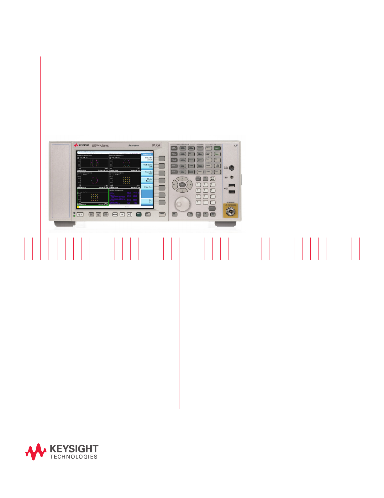
LTE and LTE-Advanced FDD/TDD
X-Series Measurement Application
N9080B and N9082B
Technical Overview
– Perform LTE plus LTE-Advanced FDD and TDD base station
(eNB) and user equipment (UE) transmitter tests
– Accelerate measurements with one-button RF conformance
tests as dened by 3GPP TS 36.141 and 36.521 specication
– Analyze carrier-aggregated signal of up to 5 contiguous/
noncontiguous component carriers
– Use hardkey/softkey manual user interface and SCPI remote
user interface
– Leverage built-in, context-sensitive help
– Extend test assets with transportable licenses between X-Series
(PXA/MXA/EXA) signal analyzers
Page 2
02 | Keysight | LTE and LTE-Advanced FDD/TDD X-Series Measurement Application N9080B and N9082B - Technical Overview
LTE/LTE-Advanced FDD and TDD Measurement
Applications
The LTE/LTE-Advanced FDD and TDD measurement applications transform the X-Series
signal analyzers into 3GPP LTE/LTE-Advanced standard-based RF transmitter testers. The
applications provide fast, one-button RF conformance measurements to help you design,
evaluate, and manufacture your LTE and LTE-Advanced base stations (eNB) and user
equipment (UE). The measurement applications closely follow the 3GPP standard, allowing
you to stay on the leading edge of your design and manufacturing challenges.
X-Series signal analyzers
The Keysight X-Series is an evolutionary approach to signal analysis that spans
instrumentation, measurements, and software. It gives you the exibility to satisfy your
business and technical requirements across multiple products and programs—now and in
the future. Optimize your investment and extend instrument longevity with upgradeable
CPU, memory, disk drives, and I/O ports. Proven algorithms, 100% code-compatibility,
and a common UI across the platform create a consistent measurement framework for
repeatable results and measurement integrity so you can leverage your test system
software through all phases of product development.
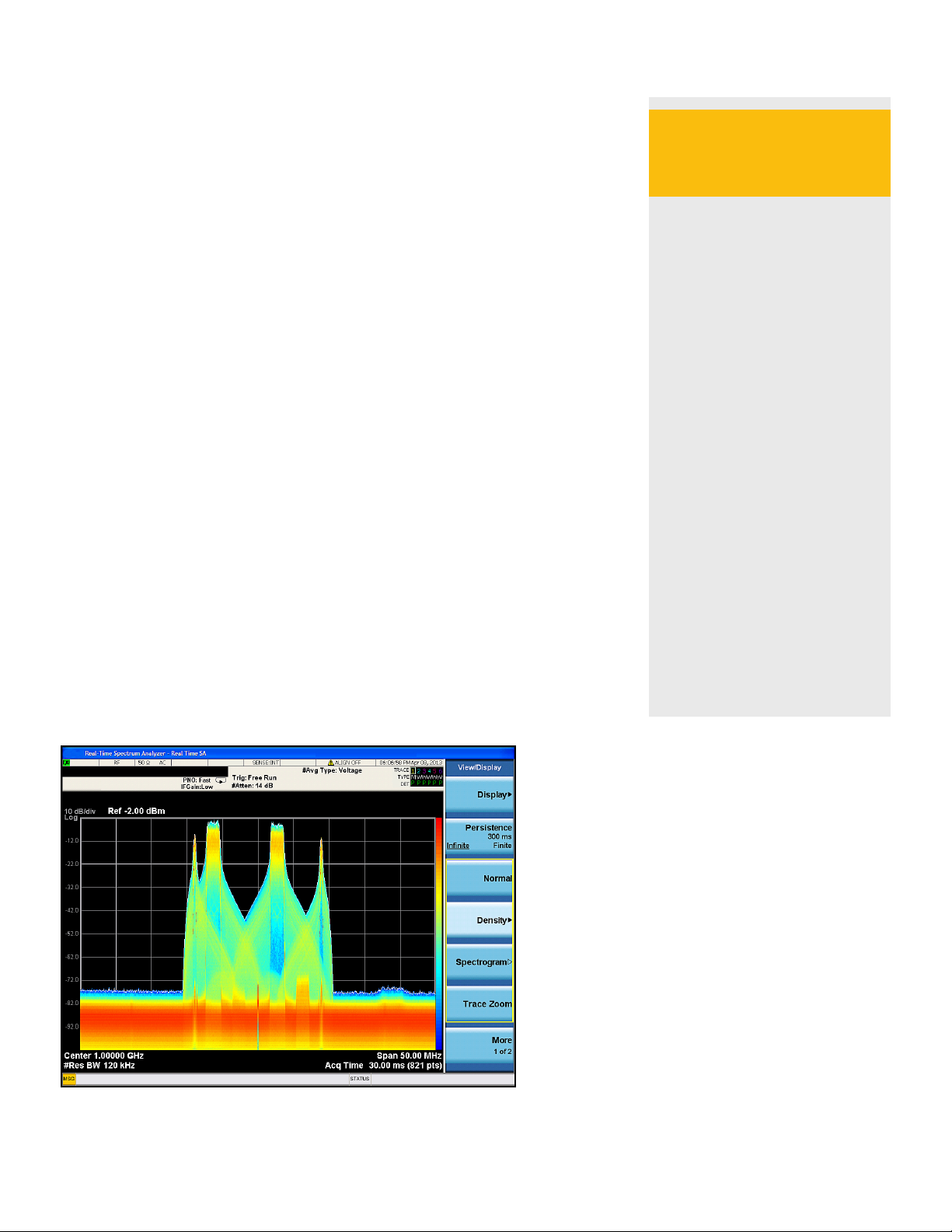
Real-time spectrum
analysis for LTE/LTEAdvanced
Adding real-time spectrum
analysis to a PXA or MXA
signal analyzer addresses
the measurement challenges
associated with dynamic
RF signals such as bursted
transmissions of LTE/LTEAdvanced-TDD, and enables
identication of interference
caused by signals in adjacent
bands or in the case of intraband, non-contiguous carrier
aggregation in adjacent sub-
blocks.
X-Series measurement applications
X-Series measurement applications increase the capability and functionality of Keysight
signal analyzers to speed time to insight. They provide essential measurements for specic
tasks in general-purpose, cellular communications, wireless connectivity and digital
video applications, covering more than 40 standards or modulation types. Applications
are supported on both benchtop and modular, with the only difference being the level
of performance achieved by the hardware you select. Choose the level of performance
necessary for your application and have full assurance that the calculations and algorithms
are the same across your signal analyzers, from development through manufacturing.
Further extend your test assets by transporting these applications across multiple X-Series
analyzers.
– Accurately observe power
changes for an LTE signal
within a 160 MHz real-time
bandwidth.
– Capture random interfering
signals with durations as
short as 3.57 μs.
– Perform fast, wideband
measurements without
compromising EVM, ACPR,
or other RF measurements.
Page 3

03 | Keysight | LTE and LTE-Advanced FDD/TDD X-Series Measurement Application N9080B and N9082B - Technical Overview
LTE/LTE-Advanced FDD and TDD Overview
LTE is the long term evolution of 3GPP’s universal mobile telephone system (UMTS).
The aim of LTE is to provide a new radio access technology focused on packet-switched
data only. Multiple requirements are set to achieve increased downlink and uplink peak
data rates, scalable channel bandwidths, spectral efciency improvements, control/
user-plane latency, and co-existence with legacy standards while evolving towards an
all-IP network. LTE accommodates both paired spectrum for frequency division duplex
(FDD) and unpaired spectrum for time division duplex (TDD) operation. There is a high
degree of commonality between FDD and TDD modes. These two modes are coordinated
in the sense that they both share the same underlying framework including radio access
schemes orthogonal frequency division multiple access (OFDMA) for the downlink, and
single-carrier frequency division multiple access (SC-FDMA) for the uplink. Both modes
share a single radio-access specication, equally applicable to paired and unpaired
spectrum. There are some signicant differences in specications between FDD and
TDD, most notably on the physical layer in the frame structure. There are few differences
on the higher layers.
LTE-Advanced is not a new technology, instead it is an evolution step in the continuing
development of LTE. It was initially specied as part of Release 10 of the 3GPP standard
with continued evolution with additional features in Release 11 and more upcoming
features in Release 12 and beyond. The three key LTE-Advanced technologies that are
essential for meeting the ITU 4G requirements are: carrier aggregation, enhanced uplink
multiple access, and enhanced multiple antenna transmission. Carrier aggregation
is one of the key features of LTE-Advanced and the earliest deployed technologies of
LTE-Advanced. It allows two or more (up to 5) component carriers to be aggregated in
both contiguous and non-contiguous congurations in order to support up to 100 MHz
transmission bandwidth.
Table 1. Physical layer comparisons of LTE and LTE-Advanced FDD/TDD
LTE FDD
(3GPP Rel 8/9)
Radio access mode FDD TDD FDD TDD
Radio frame length 10 ms (20 slots, 10 sub-frames)
Transmission scheme Downlink: OFDMA Downlink: OFDMA
Uplink: SC-FDMA Uplink: SC-FDMA, clustered SC-FDMA
Channel bandwidth
(BW)
Data type Packet switched for both voice and data, no circuit switched
Data modulation Downlink: QPSK, 16 QAM, 64 QAM Downlink: QPSK, 16 QAM, 64 QAM
Peak data rate Downlink: 300 Mbps Downlink: 1 Gbps
MIMO technology Downlink: Up to 4x4 spatial multiplexing; transmit diversity;
Maximum: 20 MHz
1.4 MHz, 3 MHz, 5 MHz, 10 MHz, 15 MHz, 20 MHz
Uplink: QPSK, 16 QAM; 64 QAM for UE category 5 only Uplink: QPSK, 16 QAM; 64 QAM for UE categories 5, 7, and 8
Uplink: 75 Mbps Uplink: 500 Mbps
multi-user (MU) MIMO; beamforming
Uplink: MU-MIMO - more than one UE transmit in the same
time-frequency resource
LTE TDD
(3GPP Rel 8/9)
LTE-Advanced FDD
(3GPP Rel 10/11)
Maximum: 100 MHz with carrier aggregation;
BW per component carrier (CC): 1.4 MHz, 3 MHz, 5 MHz, 10
MHz, 15 MHz, 20 MHz
only
Downlink: Up to 8x8 spatial multiplexing; transmit diversity;
MU-MIMO; beamforming
Uplink: Up to 4x4 spatial multiplexing for data (PUSCH);
transmit diversity for control (PUCCH); MU-MIMO
LTE-Advanced TDD
(3GPP Rel 10/11)
Page 4

04 | Keysight | LTE and LTE-Advanced FDD/TDD X-Series Measurement Application N9080B and N9082B - Technical Overview
RF Transmitter Tests
With the LTE/LTE-Advanced FDD and TDD measurement applications, you can perform
RF transmitter measurements on eNB and UE devices in time, frequency, and modulation
domains. Measurement setups are simplied with automatic detection of downlink
channels and signals. For eNB conformance testing, measurement is simplied by
recalling E-TM presets according to 3GPP TS 36.141 specication.
For LTE-Advanced demodulation measurements, such as EVM and frequency error, the
measurement application uses an automatic sequencing function, instead of a single
wideband capture of the multi-carrier signal, eliminating the need for the wide analysis
bandwidth option on the signal analyzer and thereby reducing the overall test equipment
cost. The measured results of up to 5 CCs for LTE-Advanced can be viewed side-by-
side and represented in multiple domains such as resource block, sub-carrier, slot, or
symbol. Graphical displays with color coding and marker coupling allows you to search
for problems faster and troubleshoot the found problems quicker. For manufacturing,
“conformance EVM” measurement provides signicant speed improvement over the
traditional EVM measurement.
In addition, the measurement applications allow you to test beyond physical layer by
using the transport layer decoding functionality. Troubleshoot transport layer problems
and verif y the channel encoding is correct by accessing data at different points in the
receiver chain such as demapped, deinterleaved, descrambled, deratematched, and
decoded data.
For unwanted emissions, 3GPP Release 11 adds LTE-Advanced RF conformance
requirements for intra-band, non-contiguous carrier aggregation because the spectrum
in the sub-block gap can be deployed by another service provider, perhaps using a
different technology. These new RF requirements are cumulative adjacent channel
leakage power (CACLR), to measure the contributions from carriers on both sides of
the sub-block gap, and cumulative spectrum emissions mask (SEM) measurement
where a new special limit mask is dened for unwanted emissions within a sub-block
gap calculated as the cumulative sum of contribution from each sub-block. The LTE-
Advanced embedded measurement application provides limits for both CACLR and SEM
in non-contiguous carrier aggregation.
Choosing between
X-Series embedded
applications and 89600
VSA software
X-Series measurement
applications provide
embedded format-specic,
one-button measurements
for X-Series analyzers. With
fast measurement speed,
SCPI programmability, pass/
fail testing, and simplicity of
operation, these applications
are ideally suited for design
verication and manufacturing.
89600 VSA software is the
industry-leading measurement
software for evaluating and
troubleshooting signals in R&D.
PC-based and supporting
numerous measurement
platforms, 89600 VSA software
provides exibility and
sophisticated measurement
tools essential to nd and x
signal problems in R&D.
www.keysight.com/nd/89600_
vsa
Page 5

05 | Keysight | LTE and LTE-Advanced FDD/TDD X-Series Measurement Application N9080B and N9082B - Technical Overview
Standard-Based RF Transmitter Tests
The RF transmitter conformance test requirements for LTE/LTE-Advanced FDD and TDD are dened in 3GPP 36.141 (eNB) and
36.521-1 (UE) of the 3GPP standard. Table 2 shows the required eNB RF transmitter tests along with the corresponding measurements
available in the X-Series and 89600 LTE/LTE-Advanced applications. Table 3 shows similar information for UE transmitter tests.
Table 2. Required base station (eNB) RF transmitter measurements and the corresponding
measurements in N9080B/N9082B and 89600 VSA
3G P P TS 3 6 .141
paragraph #
6.2 Base station output power E-TM 1.1 Channel power
6.3.2 Total power dynamic range E-TM 2
6.4 Transmit ON/OFF power
6.5.1
6.5.2 Error vector magnitude E-TM 3.2
6.5.3 Time alignment error (TAE) E-TM 1.1 MIMO summary or cross-carrier
6.5.4 DL RS power E-TM 1.1 RS Tx power (RSTP)
6.6.1 Occupied bandwidth E-TM 1.1 Occupied BW 89600-based solutions offer
6.6.2 Adjacent channel leakage power
6.6.2.6 Cumulative ACLR (LTE-Advanced
6.6.3 Operating band unwanted
6.6.3 Cumulative mask for SEM
6.6.4 Transmitter spurious emission E-TM 1.1 Spurious emissions
6.7 Transmitter intermodulation E-TM 1.1 ACP, SEM, spurious emissions
1. All of the measurements are available for single carrier (LTE) or multiple-carrier LTE-Advanced with up to 5 component carriers. N9080B/N9082B option
1FP is LTE, option 2FP is LTE-Advanced.
2. These are pre-demodulation channel power measurements. Channel power reading is also available af ter demodulation under “Error Summary” trace.
3. For N9080B/N9082B, these measurements are available under “Error Summary” trace in Mod Analysis as well as under “Conformance EVM” measurement.
For 89600, they are available under “Error Summary” trace.
4. For LTE-Advanced, this measurement is supported for contiguous carrier aggregation and requires analysis bandwidth on X-Series signal analy zer wide
enough to cover the aggregated bandwidth.
5. “MIMO Summar y”/”MIMO Info Table” traces are used to measure TAE for MIMO and Tx diversity signals. For carrier aggregation, “Cross-carrier Summary”
trace is used to measure TAE.
Transmitter test E-TM required N9080B (FDD)
N9082B (TDD)
measurement applications
OFDM symbol Tx. power (OSTP) 3OFDM symbol Tx. power
E-TM 3.1
E-TM1.1 Transmit ON/OFF power
(TDD only)
Frequency error E-TM 2
(N9082B only)
Frequency error
E-TM 3.1
3
EVM
E-TM 3.3
5
ratio (ACLR)
only)
emissions (SEM)
(LTE-Advanced only)
E-TM 1.1
E-TM 1.2
E-TM 1.1
E-TM 1.2
E-TM 1.1
E-TM 1.2
E-TM 1.1
E-TM 1.2
summary
ACP
ACP
Spectrum emission mask
Spectrum emission mask
89601B
Option BHD/BHG (FDD)
1
2
Option BHE/BHH (TDD)
Channel power using band power
2
marker
1
3
Not available
4
3
Frequency error
3
EVM
3
MIMO info table or cross-carrier
3
RS Tx power
summary
5
3
modulation-quality measurements;
for one-button, non-demodulation
measurements such as ACLR and
spectrum emission mask, the embedded
application should be used
Page 6

06 | Keysight | LTE and LTE-Advanced FDD/TDD X-Series Measurement Application N9080B and N9082B - Technical Overview
Standard-Based RF Transmitter Tests (continued)
For uplink, LTE-Advanced added transmitter RF conformance test for carrier aggregation (CA) and uplink MIMO (UL-MIMO) as shown
in Table 3. Even though demodulation of UL-MIMO spatial multiplexing is not supported in the N9080B and N9082B embedded
applications, the transmitter conformance test for UL-MIMO only requires testing the DUT at each antenna port using UL RMC (same
as LTE), so the applications can also be used for UL-MIMO RF conformance test.
Table 3. Required user equipment (UE) RF transmitter measurements and the corresponding measurements in N9080B/N9082B and 89600 VSA
3GPP TS 36.521-1 paragraph # Transmitter test N9080B (FDD) N9082B (TDD)
measurement applications
LTE Rel 8
and up
LTEAdvanced
CA
LTEAdvanced
UL-MIMO
6.2.2 6.2.2A 6.2.2B UE maximum output power (MOP)
6.2.3 6.2.3A 6.2.3B Maximum power reduction (MPR)
6.2.4 6.2.4A 6.2.4B Additional maximum power
Channel power
6.2.5
6.2.5A 6.2.5B
reduction (A-MPR)
Congured UE transmitted output
power
6.3.2 6.3.2A 6.3.2B Minimum output power
6.3.3 6.3.3A 6.3.3B Transmit off power Channel power or transmit on/off
power
6.3.4 6.3.4A 6.3.4B
On/off time mask Transmit on/off power Not available
6.3.5 6.3.5A 6.3.5B Power control Not available Not available
6.5.1 6.5.1A 6.5.1B Frequency error Frequency error 1 and frequency
error per slot 2
EVM
1
1
6.5.2.1 6.5.2A.1 6.5.2B.1 Error vector magnitude (EVM) EVM
6.5.2.1A N/A N/A PUSCH-EVM with exclusion
period
6.5.2.2 6.5.2A.2 6.5.2B.2 Carrier leakage IQ offset 1 and IQ offset per slot 2IQ offset & IQ offset per slot
6.5.2.3 6.5.2A.3 6.5.2B.3 In-band emissions for non-
allocated RB
6.5.2.4 N/A 6.5.2B.4 EVM equalizer spectrum
atness
In-band emissions 2 (not available
for CA)
Equalizer channel frequency
response per slot
3
6.6.1 6.6.1A 6.6.1B Occupied bandwidth Occupied BW 89600-based solutions offer
6.6.2.1 6.6.2.1A 6.6.2.1B Spectrum emission mask (SEM) SEM
6.6.2.2 6.6.2.2A 6.6.2.2B Additional SEM SEM
6.6.2.3 6.6.2.3A 6.6.2.3B Adjacent channel leakage power
ACP
ratio (ACLR)
6.6.3.1 6.6.3.1A 6.6.3B.1 Transmitter spurious emission Spurious emissions
6.6.3.2 6.6.3.2A 6.6.3B.2 Spurious emission band UE
Spurious emissions
co-existence
6.6.3.3 6.6.3.3A 6.6.3B.3 Additional spurious emissions Spurious emissions
6.7 6.7A 6.7B Transmit intermodualtion ACP
N/A N/A 6.8B Time alignment Time offset
1. These values are found in “Error Summary” table under Mod Analysis measurement or under Conformance EVM measurement for N9080B and N9082B.
2. These measurements are part of the Mod Analysis measurement. Once in Mod Analysis, they are found under [Trace/Detector] -> {Data} > {Demod Error}.
3. This measurement is part of the Mod Analysis measurement. Once in Mod Analysis, it is found under [Trace/Detector] -> {Data} > {Response}.
1
89601B Option BHD/BHG (FDD)
Option BHE/BHH (TDD)
Channel power using band power
marker
Frequency error and frequency
error per slot trace
EVM
EVM
In-band emissions (not available
for CA)
Per slot equalizer channel
frequency response
modulation-quality measurements.
For one-button, non-demodulation,
measurements such as ACLR and
spectrum emission mask, the
embedded application should be
used.
Time offset
Page 7

07 | Keysight | LTE and LTE-Advanced FDD/TDD X-Series Measurement Application N9080B and N9082B - Technical Overview
Standard-Based RF Transmitter Tests (continued)
Measurement details
All of the RF transmitter measurements as dened by the 3GPP standard, as well as a wide range of additional measurements and
analysis tools are available with a press of a button (Table 4 and 5). These measurements are fully remote controllable via the IEC/IEEE
bus or LAN, using SCPI commands.
Analog baseband measurements for LTE/LTE-Advanced are available on a PXA or MXA signal analyzer equipped with BBIQ hardware.
Supported baseband measurements include all of the modulation quality plus I/Q waveform measurement.
It is important to note that the measurements shown in Tables 4-5 for LTE FDD and TDD are available for a single carrier, while the
measurements for LTE-Advanced FDD and TDD columns are available for multiple carriers with up to 5 component carriers.
Measurement details for eNB transmitter test
Table 4. List of eNB measurements provided by N9080B and N9082B measurement applications
Technology LTE FDD LTE-Advanced FDD LTE TDD LTE-Advanced TDD
X-Series measurement application N90 80B-1FP N9080B-2FP N9082B-1FP N9082B-2FP
X-Series signal analyzer PXA, MXA, EXA
Modulation quality (error summary table)
– EVM (RMS, peak, data, RS)
– Channel power
– RS Tx. power (RSTP)
– OFDM symbol Tx. power (OSTP)
– RS Rx. power (RSRP)
– RS SI
– RS Rx. quality (RSRQ)
– Frequenc y error
– Common tracking error
– Symbol clock error
– T ime of f se t
– IQ (Offset, gain imbalance, quad error, timing skew)
Conformance EVM
Demodulated error traces
– EVM vs. frequency (sub-carrier)
– EVM vs. time (symbol)
– EVM vs. resource block
– EVM vs. slot
– Frequency error per slot
– Power vs. resource block
– Power vs. slot
Symbols table
– Numerical values of demodulated symbols (encoded)
Decoded symbol table
– Numerical values of demodulated data include demapped,
deinterleaved, descrambled, deratematched, and decoded
data
Downlink decode table
– Decode information from PBCH, PDCCH, PHICH, and PCFICH
Frame summary table
– EVM, power, modulation format, and number of allocated RB
and RNTI for all active channels and signals
Cross-carrier summary
– Time alignment error (TAE) and channel power summary of each
CC relative to the selected reference CC
• • • •
• • • •
• • • •
• • • •
• • • •
• • • •
• • • •
• • • •
• • • •
• • • •
• • • •
• • • •
• • • •
• • • •
• • • •
• • • •
• • • •
• • • •
• • • •
• • • •
• • • •
• • • •
• • • •
• • • •
• •
Page 8

08 | Keysight | LTE and LTE-Advanced FDD/TDD X-Series Measurement Application N9080B and N9082B - Technical Overview
Standard-Based RF Transmitter Tests (continued)
Table 4. List of eNB measurements provided by N9080B and N9082B measurement applications
(continued)
Technology LTE FDD LTE-Advanced FDD LTE TDD LTE-Advanced TDD
X-Series measurement application N90 80B-1FP N9080B-2FP N9082B-1FP N9082B-2FP
X-Series signal analyzer PXA, MXA, EXA
TX diversity MIMO (up to 4 Tx antenna) traces
– Info table
– RS power
– RS EVM
– RS CTE
– RS timing
– RS phase
– RS symbol clock
– RS frequency
– IQ gain imbalance
– IQ quadrature error
– IQ time skew
– Channel frequency response
– Channel frequency response difference
– Equalizer impulse response
– Common tracking error
Detected allocations trace (resource block vs. symbol)
Response
– Equalizer channel frequency response
– Instantaneous equalizer channel frequency response
– Equalizer channel frequency response difference
– Instantaneous equalizer channel frequency response difference
– Equalizer impulse response
Channel power
ACP
Cumulative ACLR (CACLR)
Transmit on/off power
Spectrum emission mask (SEM)
Cumulative SEM
Spurious emissions
Occupied bandwidth
CCDF
Monitor spectrum
I/Q waveform
• • • •
• • • •
• • • •
• • • •
• • • •
• • • •
• • • •
• • • •
• • • •
• • • •
• • • •
• • • •
• • • •
• • • •
• • • •
• • • •
• • • •
• • • •
• • • •
• • • •
• • • •
• • • •
• •
• •
• • • •
• •
• • • •
• • • •
• • • •
• • • •
• • • •
Page 9

09 | Keysight | LTE and LTE-Advanced FDD/TDD X-Series Measurement Application N9080B and N9082B - Technical Overview
Standard-Based RF Transmitter Tests (continued)
Table 5. List of UE measurements provided by N9080B and N9082B measurement applications
Technology LTE FDD LTE-Advanced FDD LTE TDD LTE-Advanced TDD
X-Series measurement application N90 80B-1FP N9080B-2FP N9082B-1FP N9082B-2FP
X-Series signal analyzer PXA, MXA, EXA
Modulation quality (error summary trace)
– EVM (RMS, peak, data, RS)
– Fre quenc y error
– Common tracking error
– Symbol clock error
– T ime of f se t
– IQ (offset, gain imbalance, quad error, timing skew)
– Channel power
– In-band emissions result
– Spectral atness result
Conformance EVM
In-band emissions
Spectrum atness (eq. ch freq response per slot)
Demodulated error traces
– EVM vs. frequency (sub-carrier)
– EVM vs. time (symbol)
– EVM vs. resource block
– EVM vs. slot
– IQ offset per slot
– Frequency error per slot
– Power vs. resource block
– Power vs. slot
Symbols table
– Numerical values of demodulated symbols (encoded)
Decoded symbol table
– Numerical values of demodulated data and descrambled
data for PUSCH
Frame summary table
– EVM, power, modulation format and number of allocated
RB for all active channels and signals
Detected allocations trace (resource block vs. symbol)
Response
– Equalizer channel frequency response
– Instantaneous equalizer channel frequency response
– Equalizer channel frequency response difference
– Instantaneous equalizer channel frequency response
difference
– Equalizer impulse response
– Equalizer channel frequency response per slot
Channel power
ACP
Transmit on/off power
Spectrum emission mask (SEM)
Spurious emissions
Occupied bandwidth
CCDF
Monitor spectrum
I/Q waveform
• • • •
• • • •
• • • •
• • • •
• • • •
• • • •
• • • •
•
Not available for CA
• • • •
• • • •
•
Not available for CA
• • • •
• • • •
• • • •
• • • •
• • • •
• • • •
• • • •
• • • •
• • • •
• • • •
• • • •
• • • •
• • • •
• • • •
• • • •
• • • •
• • • •
• • • •
• • • •
• • • •
• • • •
• • • •
• • • •
• • • •
• • • •
• • • •
• • • •
• • • •
•
•
•
Not available for CA
•
Not available for CA
•
•
Page 10
10 | Keysight | LTE and LTE-Advanced FDD/TDD X-Series Measurement Application N9080B and N9082B - Technical Overview
Standard-Based RF Transmitter Tests (continued)
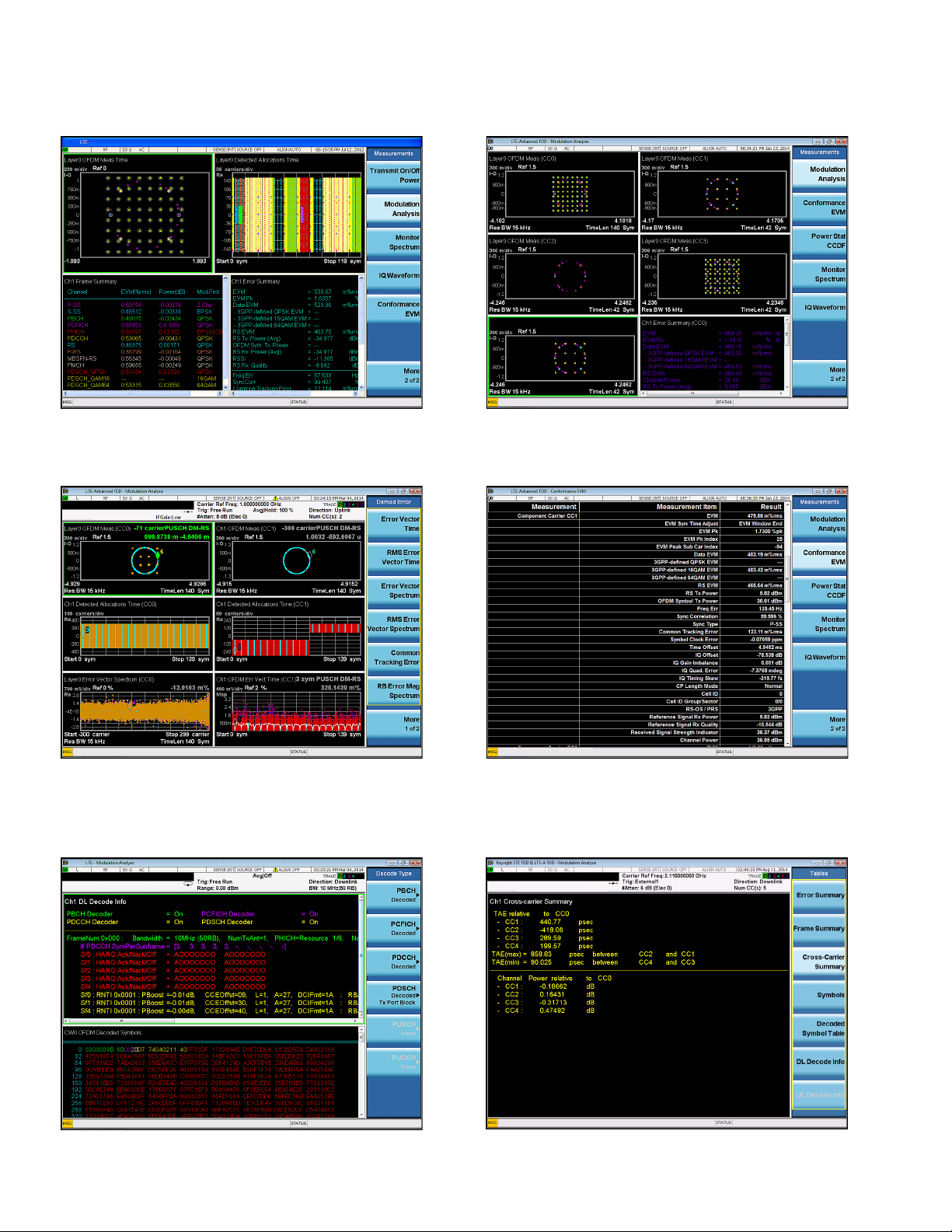
Figure 1. LTE downlink modulation analysis measurement showing
constellation, detected allocation, frame summary, and error summary
information. Measurements are color-coded based on channel type for
ease of troubleshooting.
Figure 3. Uplink modulation analysis measurement showing constellation,
EVM vs. subcarrier, detected allocation, and EVM vs. symbol information
for two component carriers. Measurements are color-coded based
on channel t ype and up to 12 markers with marker coupling between
measurements are available for easier troubleshooting.
Figure 2. LTE-Advanced downlink modulation analysis showing
constellation of ve component carriers side-by-side.
Figure 4. Conformance EVM measurement showing all required
modulation quality metrics. This measurement is optimized for
manufacturing because of its fast measurement speed.
Figure 5. Downlink transpor t layer channel decoding measurement
showing decoded information for PBCH, PDCCH, PCFICH, and PHICH
channels. Similar capability is also available for uplink.
Figure 6. LTE-Advanced cross-carrier summary trace showing
time alignment error (TAE) and channel power of each CC relative
to CC0.
Page 11
11 | Keysight | LTE and LTE-Advanced FDD/TDD X-Series Measurement Application N9080B and N9082B - Technical Overview
Standard-Based RF Transmitter Tests (continued)
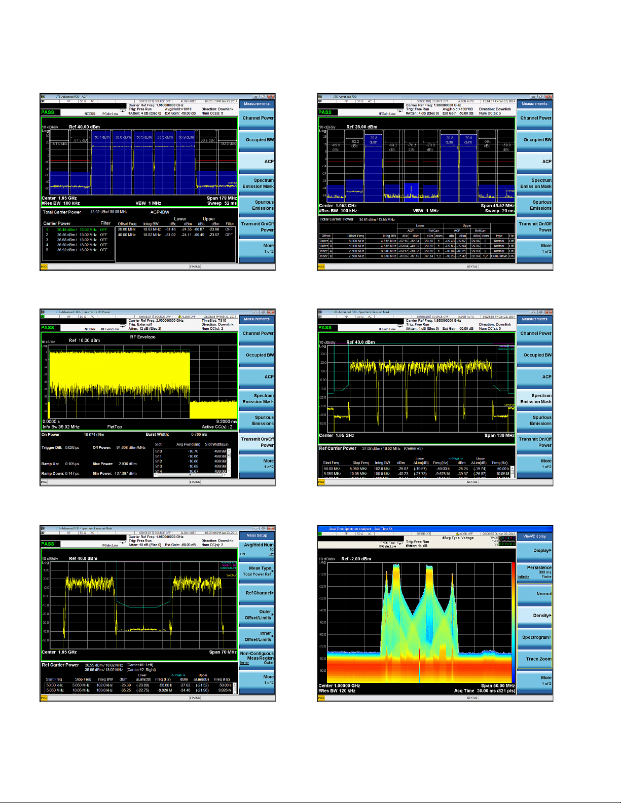
Figure 7. LTE-Advanced ACLR measurement with 5 contiguous
component carriers.
Figure 9. Transmit ON/OFF power measurement of an LTE-Advanced TDD
downlink signal with two component carriers.
Figure 8. LTE-Advanced cumulative ACLR (CACLR) for non-contiguous
carrier aggregation.
Figure 10. SEM measurement can be made on single carrier LTE or up to
5 component carrier LTE-Advanced signal.
Figure 11. LTE-Advanced non-contiguous carrier aggregation SEM
measurement with special cumulative mask inside the sub-block gap.
Figure 12. Real-time view of LTE-Advanced FDD uplink with simultaneous
PUCCH and frequency hopped PUSCH signal conguration using the
RTSA option on a PX A or MXA signal analyzer.
Page 12

12 | Keysight | LTE and LTE-Advanced FDD/TDD X-Series Measurement Application N9080B and N9082B - Technical Overview
Key Specications
Denitions
– Specications describe the performance of parameters covered by the product warranty.
– The specications apply to single carrier case only, unless otherwise stated.
– 95th percentile values indicate the breadth of the population (≈2σ) of performance tolerances expected to be met in 95% of cases
with a 95% condence. These values are not covered by the product warranty.
– Typical values are designated with the abbreviation "typ." These are performance beyond specication that 80% of the units
exhibit with a 95% condence. These values are not covered by the product warranty.
– Nominal values are designated with the abbreviation "nom." These values indicate expected performance, or describe product
performance that is useful in the application of the product, but is not covered by the product warranty.
Note: Data subject to change.
Supported devices and standards
Device type LTE FDD/TDD N9080B-1FP/ N9082B-1FP LTE-Advanced FDD/TDD N9080B-2FP/ N9082B-2FP
3GPP standards supported 36.211 V9.1.0 (March 2010)
36.212 V9.4.0 (September 2011)
36.213 V9.3.0 (September 2010)
36.214 V9.2.0 (June 2010)
36.141 V9.10.0 (July 2012)
36.521-1 V9.8.0 (March 2012)
Signal structure FDD Frame Structure Type 1
TDD Frame Structure Type 2
Special subframe congurations 0-8
Signal direction Uplink and downlink
UL/DL congurations 0-6
Signal bandwidth 1.4 MHz (6 RB), 3 MHz (15 RB), 5 MHz (25 RB), 10 MHz
(50 RB), 15 MHz (75 RB), 20 MHz (100 RB)
Number of component carriers 1 1, 2, 3, 4, or 5
Physical signals
– Dow nlink PBCH, PCFICH, PHICH, PDCCH, PDSCH, PMCH
– Uplink PUCCH, PUSCH, PRACH
Physical channels
– Dow nlink P-SS, S-SS, C-RS, UE-RS, P-PS (positioning), MBSFN-RS P-SS, S-SS, C-RS, UE-RS, P-PS (positioning), MBSFN-RS,
– Uplink PUCCH-DMRS, PUSCH-DMRS, S-RS (sounding) PUCCH-DMRS, PUSCH-DMRS, S-RS (sounding)
36.211 V10.7.0 (March 2013)
36.212 V10.7.0 (December 2012)
36.213 V10.9.0 (March 2013)
36.214 V10.12.0 (March 2013)
36.141 V11.4.0 (March 2013)
36.521-1 V10.5.0 (March 2013)
FDD Frame Structure Type 1
TDD Frame Structure Type 2
Special subframe congurations 0-9
Uplink and downlink
UL/DL congurations 0-6
Bandwidth per component carrier:
1.4 MHz (6 RB), 3 MHz (15 RB), 5 MHz (25 RB),
10 MHz (50 RB), 15 MHz (75 RB), 20 MHz (100 RB)
CSI-RS
For a complete list of specications refer to the appropriate specications guide.
PXA: http://www.keysight.com/nd/pxa_specications
MXA: http://www.keysight.com/nd/mxa_specications
EXA: http://www.keysight.com/nd/exa_specications
Page 13

13 | Keysight | LTE and LTE-Advanced FDD/TDD X-Series Measurement Application N9080B and N9082B - Technical Overview
Key Specications (continued)
Description PXA MXA EXA
Channel power
Minimum power at RF input –50 dBm (nom)
Power accuracy ± 0.63 dB ± 0.82 dB ± 1.04 dB
Power accuracy (95% condence) ± 0.19 dB ± 0.23 dB ± 0.27 dB
Measurement oor (@ 10 MHz BW) –81.7 dBm (nom) –79.7 dBm (nom) –76.7 dBm (nom)
Transmit on/off power (only applies to N9082B)
Burst type Trafc, UpPTS, DwPTS, SRS, PRACH
Measurement time Up to 20 slots
Dynamic range for 5 MHz BW
Adjacent channel power
Minimum power at RF input —36 dBm (nom)
Accuracy
Radio Offset frequency
MS Adjacent ± 0.07 dB (5 MHz)
BTS Adjacent ± 0.23 dB (5 MHz)
BTS Alternate ± 0.11 dB (5 MHz)
Dynamic range E-UTRA
Offset Channel BW
Adjacent 5 MHz 83.5 dB (nom)
Adjacent 10 MHz 82.1 dB (nom)
Adjacent 20 MHz Not available 71.7 dB (nom)
Alternate 5 MHz 86.7 dB (nom)
Alternate 10 MHz 83.7 dB (nom)
Alternate 20 MHz Not available 72.1 dB (nom)
Dynamic range UTRA
Offset Channel BW
2.5 MHz 5 MHz 86.2 dB (nom)
2.5 MHz 10 MHz 84.2 dB (nom)
2.5 MHz 20 MHz Not available 75.0 dB (nom)
7.5 MHz 5 MHz 87.3 dB (nom)
7.5 MHz 10 MHz 87.0 dB (nom)
7.5 MHz 20 MHz Not available 78.1 dB (nom)
1
124.5 dB (nom) 124.5 dB (nom) 122.5 dB (nom)
± 0.11 dB (10 MHz)
± 0.21 dB (20 MHz)
± 0.13 dB (5 MHz)
± 0.20 dB (10 MHz)
± 0.38 dB (20 MHz)
± 0.16 dB (5 MHz)
± 0.24 dB (10 MHz)
± 0.41 dB (20 MHz)
(ACPR range –33 to –27 dBc with Opt ML)
± 0.33 dB (10 MHz)
± 0.52 dB (20 MHz)
± 0.57 dB (5 MHz)
± 0.82 dB (10 MHz)
± 1.19 dB (20 MHz)
± 1.03 dB (5 MHz)
± 1.29 dB (10 MHz)
± 2.04 dB (20 MHz)
(ACPR range –48 to –42 dBc with Opt ML)
± 0.21 dB (10 MHz)
± 0.40 dB (20 MHz)
± 0.21 dB (5 MHz)
± 0.35 dB (10 MHz)
± 0.65 dB (20 MHz)
± 0.24 dB (5 MHz)
± 0.39 dB (10 MHz)
± 0.74 dB (20 MHz)
(ACPR range –48 to –42 dBc with Opt ML)
(Opt ML –8.5 dBm)
(Opt ML –8.3 dBm)
74.2 dB (nom)
(Opt ML –18.4 dBm)
73.8 dB (nom)
(Opt ML –18.4 dBm)
70.0 dB (nom)
(Opt ML –16.5 dBm)
69.3 dB (nom)
(Opt ML –16.5 dBm)
68.4 dB (nom)
(Opt ML –8.5 dBm)
(Opt ML –8.3 dBm)
(Opt ML –18.2 dBm)
77.6 dB (nom)
(Opt ML –18.6 dBm)
75.1 dB (nom)
(Opt ML –18.4 dBm)
(Opt ML –16.3 dBm)
75.8 dB (nom)
(Opt ML –16.6 dBm)
73.2 dB (nom)
(Opt ML –16.3 dBm)
70.3 dB (nom)
(Opt ML –8.5 dBm)
(Opt ML –8.3 dBm)
(Opt ML –18.2 dBm)
75.9 dB (nom)
(Opt ML –18.5 dBm)
76.2 dB (nom)
( Opt ML –18.4 dBm)
(Opt ML –16.3 dBm)
70.5 dB (nom)
(Opt ML –16.6 dBm)
70.5 dB (nom)
(Opt ML –16.4 dBm)
71.4 dB (nom)
(Opt ML –8.7 dBm)
(Opt ML –8.4 dBm)
(Opt ML –18.2 dBm)
78.4 dB (nom)
(Opt ML –18.5 dBm)
78.6 dB (nom)
(Opt ML –18.4 dBm)
(Opt ML –16.3 dBm)
76.5 dB (nom)
(Opt ML –16.6 dBm)
76.5 dB (nom)
(Opt ML –16.4 dBm)
75.7 dB (nom)
(Opt ML –18.2 dBm)
(Opt ML –16.3 dBm)
1. This dynamic range is for the case of 5 MHz information bandwidth. For other information bandwidths, the dynamic range can be derived using the following
equation: Dynamic Range = Dynamic Range for 5 MHz – 10*log10 (Info BW/5.0e6).
Page 14

14 | Keysight | LTE and LTE-Advanced FDD/TDD X-Series Measurement Application N9080B and N9082B - Technical Overview
Key Specications (continued)
Description PXA MXA EXA
Spectrum emission mask
Dynamic range
– 5 MHz
– 10 MH z
– 20 MHz
Sensitity –98.5 (–101.5 dBm typ) –94.5 (–99.5 dBm typ) –92.5 (–96.5 dBm typ)
Accuracy
– Rel ati ve
– Ab solute
Spurious emissions
Dynamic range, relative 88.8 (92.1 dB typ) 81.3 (82.2 dB typ) 76.9 (77.4 dB typ)
Sensitivity, absolute –88.5 (–91.5 dBm typ) –84.5 (–89.5 dBm typ) –82.5 (–86.5 dBm typ)
Accuracy (attenuation = 10 dB) ± 0.19 dB (95%) ± 0.29 dB (95%) ± 0.38 dB (95%)
– Frequency range 20 Hz to 3.6 GHz 20 Hz to 3.6 GHz 9 kHz to 3.6 GHz
– Frequency range ± 1.08 dB (95%)
– Frequency range ± 1.48 dB (95%)
Occupied bandwidth
Minimum power at RF input –30 dBm (nom)
Frequency accuracy ± 10 kHz (RBW = 30 kHz, Number of points = 1001, Span = 10 MHz)
Modulation analysis
Input range Signal level within one range step of overload
OSTP/RSTP
1
Absolute accuracy ± 0.21 dB (nom) ± 0.27 dB (nom) ± 0.30 dB (nom)
EVM oor for downlink (OFDMA)
2
Signal bandwidth
– 5 MHz 0.34% (–49.3 dB)
– 10 MH z 0.35% (–49.1 dB)
– 20 MHz 0.39% (–48.1 dB)
EVM oor for downlink (OFDMA) with Option BBA
Signal bandwidth
– 5 MHz 0.18% (–54.8 dB) nom 0.18% (–54.8 dB) nom
– 10 MH z 0.18% (–54.8 dB) nom 0.18% (–54.8 dB) nom
– 20 MHz 0.18% (–54.8 dB) nom 0.18% (–54.8 dB) nom
EVM accuracy for Downlink (OFDMA)
EVM range: 0 to 8% ± 0.3% nom ± 0.3% nom ± 0.3% nom
EVM oor for uplink (SC-FDMA)
2
Signal bandwidth
– 5 MHz 0.31% (–50.1 dB)
– 10 MH z 0.32% (–49.8 dB)
– 20 MHz 0.35% (–49.1 dB)
1. The accuracy specication applies when EVM is less than 1% and no power boost is applied on reference signal.
2. For MXA and EX A instruments with serial number prex ≥ MY/SG/US5233 and ≥ MY/SG/US5340, which ship standard with N9020A-EP2 and N9010A-EP3.
Refer to the LTE section in the MXA and EX A specication guides for more information: www.keysight.com/nd/mxa_specications; www.keysight.com/
nd/exa_specications.
3. The accuracy specication applies when the EVM to be measured is well above the measurement oor. When the EVM does not greatly exceed the oor, the
errors due to the oor add to the accuracy errors. Refer to specication guide for information on calculating the errors due to the oor.
82.9 (86.8 dB typ) 76.2 (82.9 dB typ) 72.6 (79.4 dB typ)
86.6 (90.7 dB typ) 77.8 (83.8 dB typ) 73.5 (80.3 dB typ)
84.3 (89.7 dB typ) 78.2 (84.9 dB typ) 73.4 (80.6 dB typ)
± 0.06 dB ± 0.13 dB ± 0.13 dB
± 0.62 (± 0.20 dB 95%) ± 0.88 (± 0.27 dB 95%) ± 1.15 (± 0.31 dB 95%)
3.5 GHz to 8.4 GHz
8.3 GHz to 13.6 GHz
± 1.17 dB (95%)
3.5 GHz to 8.4 GHz
± 1.54 dB (95%)
8.3 GHz to 13.6 GHz
± 1.22 dB (95%)
3.5 GHz to 7.0 GHz
± 1.59 dB (95%)
6.9 GHz to 13.6 GHz
0.36% (–48.8 dB) 0.68% (–43.3 dB)
0.28% (–51.2 dB) nom
0.36% (–48.8 dB) 0.68% (–43.6 dB)
0.31% (–50.3 dB) nom
0.40% (–47.9 dB) 0.72% (–43.0 dB)
0.34% (–49.5 dB) nom
3
0.35% (–49.1 dB) 0.66% (–43.6 dB)
0.21% (–53.5 dB) nom
0.35% (–49.1 dB) 0.66% (–43.6 dB)
0.21% (–53.5 dB) nom
0.40% (–47.9 dB) 0.70% (–43.0 dB)
0.22% (–53.2 dB) nom
Page 15

15 | Keysight | LTE and LTE-Advanced FDD/TDD X-Series Measurement Application N9080B and N9082B - Technical Overview
Key Specications (continued)
Description PXA MXA EXA
Frequency error
Lock range ± 2.5 x subcarrier spacing = 37.5 kHz for default 15 kHz subcarrier spacing (nom)
Accuracy ± 1 Hz + tfa 1 (nom)
Time offset
Absolute frame offset accuracy ± 20 ns ± 20 ns ± 20 ns
Relative frame offset accuracy ± 5 ns (nom) ± 5 ns (nom) ± 5 ns (nom)
MIMO RS timing accuracy ± 5 ns (nom) ± 5 ns (nom) ± 5 ns (nom)
1. tfa = transmitter frequency x frequency reference accuracy.
2. The accuracy specication applies when EVM is less than 1% and no power boost is applied for resource elements.
2
Page 16

16 | Keysight | LTE and LTE-Advanced FDD/TDD X-Series Measurement Application N9080B and N9082B - Technical Overview
Ordering Information
Software licensing and conguration
Choose from two license types:
Try Before You Buy!
– Fixed, perpetual license:
This allows you to run the application in the X-Series analyzer in which it is initially
installed.
– Transportable, perpetual license:
This allows you to run the application in the X-Series analyzer in which it is initially
installed, plus it may be transferred from one X-Series analyzer to another.
Free 30-day trials of X-Series
measurement applications
provide unrestricted use of
each application’s features and
functionality on your X-Series
analyzer. Redeem a trial license
on-line today:
www.keysight.com/nd/XSeries_trial
You Can Upgrade!
Options can be added af ter your
initial purchase.
All of our X-Series application
options are license-key
upgradeable.
The table below contains information on our xed, perpetual licenses. For more information, please visit the product web pages.
N9080B LTE/LTE-Advanced FDD measurement application
Model-Option Description Additional information
N9080B-1FP LTE FDD measurement application, xed perpetual license
N9080B-1TP LTE FDD measurement application, transportable perpetual license
N9080B-2FP LTE-Advanced FDD measurement application, xed perpetual license Requires 1FP
N9080B-2TP LTE-Advanced FDD measurement application, transportable perpetual license Requires 1TP
Note: N9080B application requires Windows 7 operating system in X-Series signal analyzers. For more information, see hardware conguration below.
N9082B LTE/LTE-Advanced TDD measurement application
Model-Option Description Additional information
N9082B -1FP LTE TDD measurement application, xed perpetual license
N9082B -1TP LTE TDD measurement application, transportable perpetual license
N9082B-2FP LTE-Advanced TDD measurement application, xed perpetual license Requires 1FP
N9082B-2TP LTE-Advanced TDD measurement application, transportable perpetual license Requires 1TP
Note: N9082B application requires Windows 7 operating sys tem in X-Series signal analyzer s. For more information, see hardware conguration below.
Page 17

17 | Keysight | LTE and LTE-Advanced FDD/TDD X-Series Measurement Application N9080B and N9082B - Technical Overview
Hardware conguration
N9030A PXA signal analyzer
Description Model-Option Additional information
3.6, 8.4, 13.6, 26.5, 43, 44, or 50 GHz frequency
range
Operating system, Windows Embedded Standard 7 N9030A-W7X Required; ships standard on new instruments
Analog baseband IQ (BBIQ) inputs N9030A-BBA Required for analog baseband measurement
25, 40, 85, or 160 MHz analysis bandwidth N9030A-B25, -B40, -B85, -B1X One required; LTE-Advanced demodulation is sequential
Precision frequency reference N9030A-PFR Recommended
Electronic attenuator, 3.6 GHz N9030A-EA3 Recommended
Preamplier, 3.6, 8.4, 13.6, 26.5, 43, 44, or 50 GHz N9030A-P03, -P08, -P13, -P26,
N9020A MXA signal analyzer
Description Model-Option Additional information
3.6, 8.4, 13.6, or 26.5 GHz frequency range N9020A-503, -508, -513, or -526 One required
Operating system, Windows Embedded Standard 7 N9020A-W7X Required; ships standard on new instruments
Analog baseband IQ (BBIQ) inputs N9020A-BBA Required for analog baseband measurement
25, 40, 85, 125, or 160 MHz analysis bandwidth N9020A-B25, -B40, -B85, -B1A,
Precision frequency reference N9020A-PFR Recommended
Electronic attenuator, 3.6 GHz N9020A-EA3 Recommended
Preamplier, 3.6, 8.4, 13.6, or 26.5 GHz N9020A-P03, -P08, -P13, or -P26 One recommended
N9030A-503, -508, -513, -526,
-543, -544, or -550
-P43, -P44, or -P50
-B1X
One required
so > 25 MHz bandwidth is not required; LTE-Advanced
TDD transmit on/off power measurement is the only
measurement that requires bandwidth wide enough to
cover the full aggregated bandwidth
One recommended
One required; LTE-Advanced demodulation is sequential
so > 25 MHz bandwidth is not required; LTE-Advanced
TDD transmit on/off power measurement is the only
measurement that requires bandwidth wide enough to
cover the full aggregated bandwidth
N9010A EXA signal analyzer
Description Model-Option Additional information
3.6, 7.0, 13.6, 26.5, 32, or 44 GHz frequency range N9010A-503, -507, -513, -526 , 532,
or 544
Operating system, Windows Embedded Standard 7 N9010A-W7X Required; ships standard on new instruments
25, 40 MHz analysis bandwidth N9010A-B25, B40 One required; LTE-Advanced demodulation is sequential
Precision frequency reference N9010A-PFR Recommended
Electronic attenuator, 3.6 GHz N9010A-EA3 Recommended
Preamplier, 3.6, 7.0, 13.6, 26.5, 32, or 44 GHz N9010A-P03, -P07, -P13, -P26 -P32,
or -P44
One required
so > 25 MHz bandwidth is not required; LTE-Advanced
TDD transmit on/off power measurement is the only
measurement that requires bandwidth wide enough to
cover the full aggregated bandwidth
One recommended
Page 18

18 | Keysight | LTE and LTE-Advanced FDD/TDD X-Series Measurement Application N9080B and N9082B - Technical Overview
Related Literature
Description Publication number
N9080B LTE/LTE-Advanced FDD Measurement Application Measurement
Guide
N9082B LTE/LTE-Advanced TDD Measurement Application Measurement
Guide
3GPP Long Term Evolution: System Overview, Product Development, and Test
Challenges, Application Note
Introducing LTE-Advanced, Application Note 5990-6706EN
Stimulus-Response Testing for LTE Components, Application Note 5 990-5149EN
Measuring ACLR Performance in LTE Transmitters, Application Note 5990-5089EN
TD-LTE E-UTRA Base Station Transmit ON/OFF Power Measurement Using a
Keysight X-Series Signal Analyzer, Application Note
User’s and Programmer’s Reference Guide is available in the library section of
the N9080A, W9080A, N9082A and W9082A product pages.
N9080-90008
N9082-90004
5989-8139EN
5990-5989EN
Web
Product pages:
– www.keysight.com/nd/N9080B
– www.keysight.com/nd/N9082B
X-Series measurement applications:
– www.keysight.com/nd/X-Series_Apps
X-Series signal analyzers:
– www.keysight.com/nd/X-Series
Application pages:
– www.keysight.com/nd/lte
– www.keysight.com/nd/lteadvanced
Page 19

19 | Keysight | LTE and LTE-Advanced FDD/TDD X-Series Measurement Application N9080B and N9082B - Technical Overview
myKeysight
www.keysight.com/find/mykeysight
A personalized view into the information most relevant to you.
Three-Year Warranty
www.keysight.com/find/ThreeYearWarranty
Keysight’s commitment to superior product quality and lower total cost
of ownership. The only test and measurement company with three-year
warranty standard on all instruments, worldwide.
Keysight Assurance Plans
www.keysight.com/find/AssurancePlans
Up to five years of protection and no budgetary surprises to ensure your
instruments are operating to specification so you can rely on accurate
measurements.
www.keysight.com/quality
Keysight Technologies, Inc.
DEKRA Certified ISO 9001:2008
Quality Management System
Keysight Channel Partners
www.keysight.com/find/channelpartners
Get the best of both worlds: Keysight’s measurement expertise and product
breadth, combined with channel partner convenience.
For more information on Keysight
Technologies’ products, applications or
services, please contact your local Keysight
office. The complete list is available at:
www.keysight.com/find/contactus
Americas
Canada (877) 894 4414
Brazil 55 11 3351 7010
Mexico 001 800 254 2440
United States (800) 829 4444
Asia Pacic
Australia 1 800 629 485
China 800 810 0189
Hong Kong 800 938 693
India 1 800 112 929
Japan 0120 (421) 345
Korea 080 769 0800
Malaysia 1 800 888 848
Singapore 1 800 375 8100
Taiwan 0800 047 866
Other AP Countries (65) 6375 8100
Europe & Middle East
Austria 0800 001122
Belgium 0800 58580
Finland 0800 523252
France 0805 980333
Germany 0800 6270999
Ireland 1800 832700
Israel 1 809 343051
Italy 800 599100
Luxembourg +32 800 58580
Netherlands 0800 0233200
Russia 8800 5009286
Spain 0800 000154
Sweden 0200 882255
Switzerland 0800 805353
Opt. 1 (DE)
Opt. 2 (FR)
Opt. 3 (IT)
United Kingdom 0800 0260637
For other unlisted countries:
www.keysight.com/find/contactus
(BP-07-10-14)
This information is subject to change without notice.
© Keysight Technologies, 2014
Published in USA, August 28, 2014
5991-4368EN
www.keysight.com
 Loading...