

Page 1
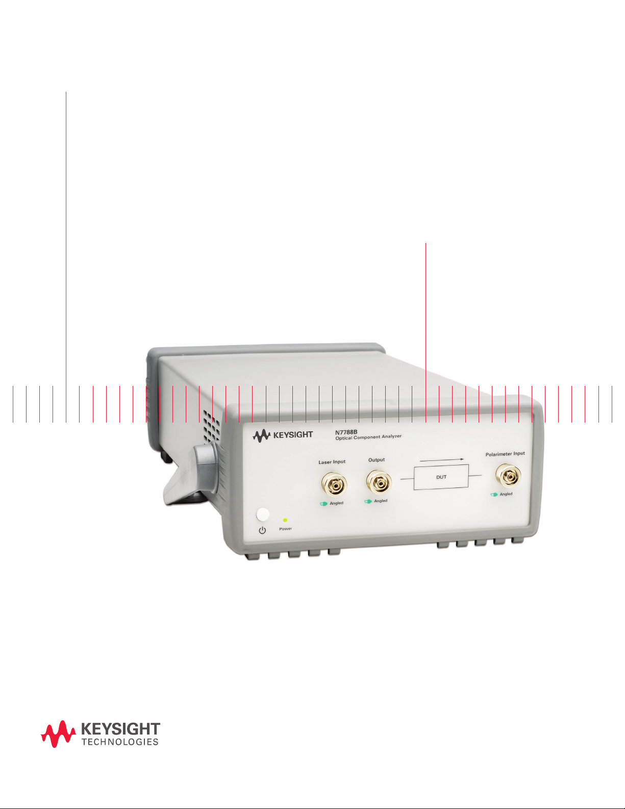
Keysight N7788B
Optical Component Analyzer
Data Sheet
N7788B optical
component analyzer
Page 2

Introduction
Keysight Technologies. Inc. pushes the limits of component measurements with the N7788B component analyzer. Its proprietary technology is comparable with the well-known Jones-Matrix-Eigenanalysis (JME) which is the standard method for measuring polarization mode dispersion (PMD)
or differential group delay (DGD) of optical devices.
For spectral measurements of polarization dependent loss and dispersion, the N7788B is combined
with a Keysight swept-wavelength tunable laser, such as the 81600B or 81960A (not included) and
the Polarization Navigator software application for single-scan measurements. Compared to the
JME, Keysight’s powerful single scan technology offers a range of advantages:
A complete set of parameters:
– DGD/PMD
– PDL
– Power/loss
– TE/TM-loss
– Jones matrices
– Mueller matrices
– 2nd-order PMD (depolarization + PCD)
Key Benets
– Highest accuracy in a single sweep: no averaging over multiple sweeps required.
– High measurement speed: Complete measurement across C/L-band in less than 10 seconds
(no need to wait for many averages).
– Robustness against ber movement/vibration and drif t: Fixing bers with sticky tape on the
table or even operation on isolated optical table is not required! The single-scan measurement
fully characterizes each wavelength point in 0.3 ms rather than after multiple sweeps over
many seconds.
– No limitation on optical path length of component.
– The internal referencing scheme guarantees reliable and accurate measurements.
Page 3
DUT
Wavelength [nm]
TE/TM loss [dB]
03 | Keysight | N7788B Optical Component Analyzer - Data Sheet
Applications
– Fiber characterization: SMF, PMF, DCF.
– Passive component testing: lters, isolators,
circulators.
– Dynamic component/module testing: OADM/
ROADM.
– Active component testing: EDFAs, SOAs,VOAs.
– Link test: in-channel measurements across
ampliers.
Designed for the
manufacturing oor
High throughput
A complete analysis across the C and the L band is performed in less than 10 seconds!
Software drivers
A range of software drivers is available for external control
of the system. This allows easy integration in common ERP
systems.
Remote control
The N7788B has USB and GPIB interfaces and can be programmed directly or operated manually or automatically
via the included Polarization Navigator software.
Keysight N7788B instrument setup
and application examples
Laser in
PMF
Power in
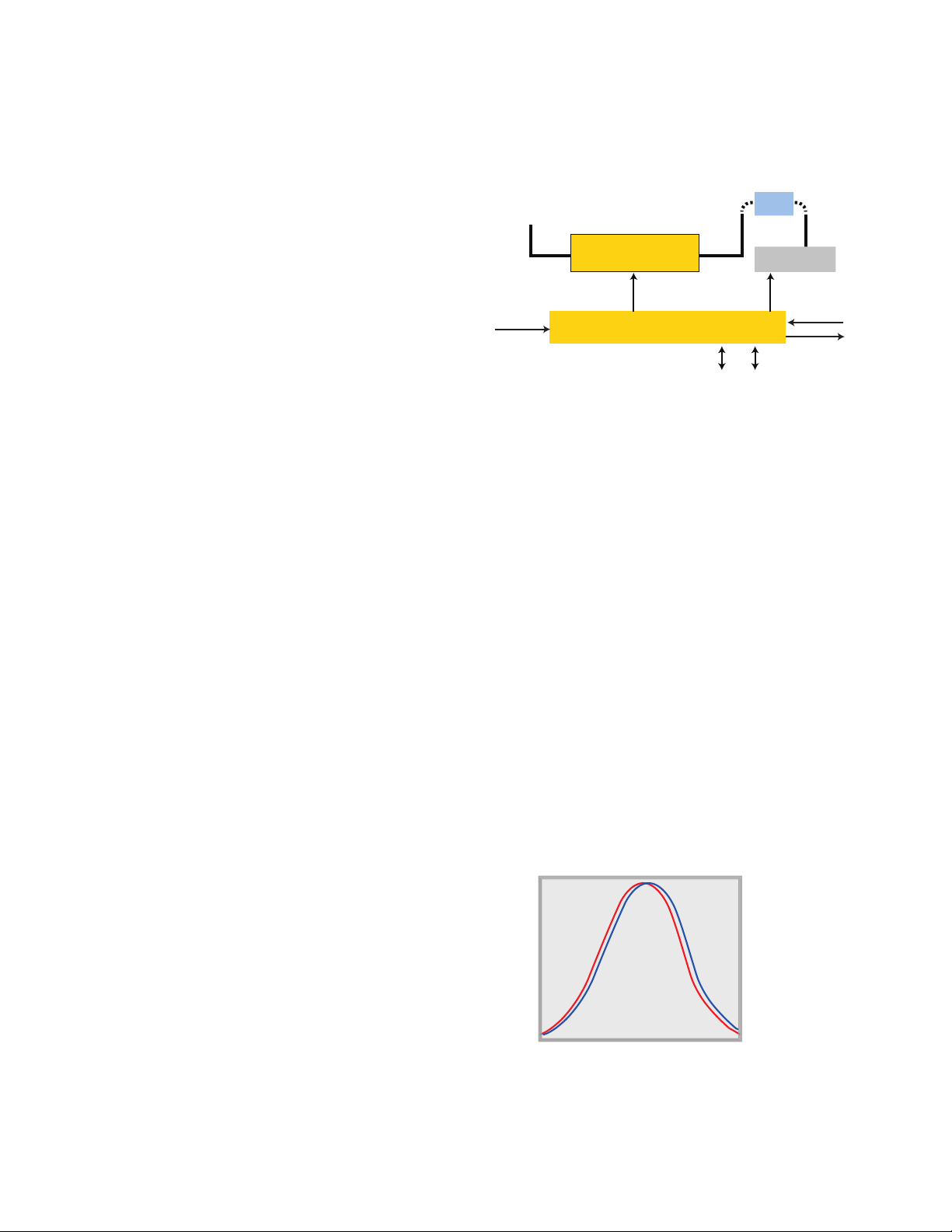
Figure 2. N7788B instrument setup.
The instrument setup is shown in the Figure 2. A LiNbO3
polarization controller deterministically varies the input
polarization to the DUT. As the tunable laser source
sweeps over the desired wavelength range, a polarimeter
analyzes the output state of polarization while the input
polarization is being modied. The result is a highly accurate device characterization with respect to DGD/PDL/
loss, etc. Furthermore, the internal optical switch provides
continuous self calibration for excellent repeatability.
LiNbOз
polarization controller
Microcontroller board
SMF
Polarimeter
Trigger in
Trigger out
USBGPIB
Resolving TE/TM insertion loss
Report generation
Generating PDF reports is supported. The content includ-
ing layout is congurable by the user.
Real time power readout
High throughput measurement of non-connectorized
components is supported by providing a real time power
readout which enables ber coupling of the new device.
Barcode scanner
Barcode scanning is supported for quick transfer of the
DUT serial number.
The TE/TM-function allows accurate determination of the
minimum and maximum loss of the DUT at each wavelength and permits determination of the polarization-
dependent frequency Pdf of lter passbands.
Due to birefringence, optical lters tend to show differ-
ent transmission functions depending on the polarization
state. As shown in Figure 3, these functions are typically
shifted in wavelength depending on the amount of birefringence.
0
-10
-20
-30
-40
-50
1559
Figure 3. Polarization-dependent wavelength shift (PD-λ) of a lter.
1560 1561
Page 4
0
Insertion loss [dB]
DGD
Wavelength
pdf DGD
Wavelength
Time
DGD
GPIB
USB or GPIB
Trig Out
InputOutput
DUT
Trig In
Optical connections
Electrical connections
Controller PC
Controller PC
TLS (81600B
or 81940/81980A)
N7788B
04 | Keysight | N7788B Optical Component Analyzer - Data Sheet
The capability of performing quick PMD-measurements
makes this measurement system well-suited to collecting
long-term PMD data. The PC software allows continuous
collection and saving of spectral PMD data. The data can
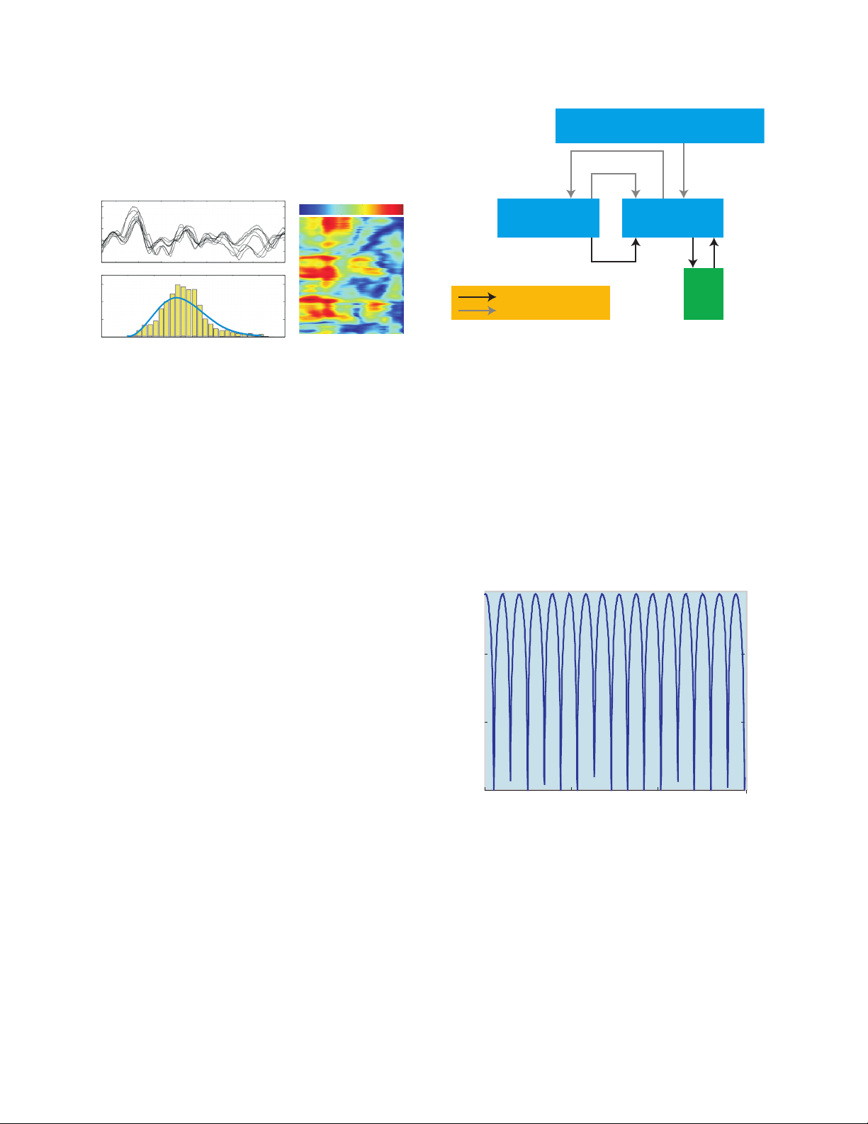
then be visualized as a pseudo-color plot (see Figure 4).
Figure 4. Long term DGD measurements.
The internal reference path allows measurement of
insertion loss spectra with excellent accuracy, further
minimizing the inuence of environmental disturbance to
the results.
Conguration for swept-wavelength
measurements
Figure 5. Schematic instrument conguration for swept-wavelength DGD/
PMD, PDL and IL measurements using the N7788B.
Due to the excellent spectral resolution, the Keysight
N7788B is best suited for intra-channel DGD/PDL
characterization.
The all-parameter-JME algorithm allows exible
adjustments of the wavelength resolution without the need
to repeat the measurement. This allows the user to easily
nd the optimum trade-off between PDL/DGD accuracy
and wavelength resolution.
The N7788B is congured so that a polarized source
like a tunable laser can be input and the polarizationcontrolled signal is then output to the front panel. It can
then be applied to a DUT and the DUT output signal is
then returned to the polarization analyzer input of the
instrument. Internal switching for automatic referencing is
also included. This setup is especially used for measuring
-10
wavelength dependent differential group delay, DGD and
PMD, together with PDL and IL with a single wavelength
sweep. The Polarization Navigator is the user interface for
the N778x-series polarization instruments and includes
-20
an application engine for this setup. This has now been
integrated into the N7700A suite and is free. Installation
requires the N7700A Main package and the Polarization
Navigator package.
-30
1521.2 1521.3 1521.4 1521.5
Wavelength [nm]
Figure 6. Loss cur ve of a DPSK demodulator.
Page 5

05 | Keysight | N7788B Optical Component Analyzer - Data Sheet
Specications 1 N7788B Optical Component Analyzer
Wavelength
Specication wavelength range 1270 nm to 1375 nm (Opt. 300, O-Band)
1270 nm to 1375 nm, 1460 nm to 1620 nm (Opt. 400, O/C/L-Band)
Operating wavelength range
2
Differential group delay
DGD uncertainty
DGD measurement range
PMD uncertainty
3
3
4
PMD repeatability (typical) ± 3 fs
PMD measurement range
4
Loss
PDL uncertainty
5
PDL repeatability (typical) ± 0.005 dB
Insertion loss uncertainty (typical)
3
Insertion loss dynamic range (typical)
Polarization analysis
SOP uncertainty (typical)
DOP uncertainty
6, 7
6
DOP uncertainty after user calibration
6, 8
(typical)
Maximum sampling rate 1 MHz
Optical power measurement
Relative power uncertainty
6
Input power range -50 dBm to +7 dBm
Maximum safe optical input power +12 dBm
1460 nm to 1620 nm (Opt. 500, C/L-Band)
1260 nm to 1640 nm
Resolution 2.0 nm ± (30 fs + 3.0% * DGD)
Resolution 0.1 nm ± (30 fs + 3.0% * DGD)
0 ps to 1000 ps
± (30 fs + 2.0% * DGD)
0 ps to 300 ps
C-Band ± (0.05 dB + 4% * PDL)
O-Band ± (0.10 dB + 4% * PDL)
C/L-B an d ± 0.03 dB
O-Band ± 0.07 dB
3
> 41 dB (for higher TLS power levels, increase value accordingly)
1.5°
± 2.0 %
± 0.5 %
C/L-Band: ± -.03 dB (± 0.02 dB typical)
O-Band: ± 0.07 dB (± 0.04 dB typical)
Polarization control
SOP switching time < 10 μs
PDL (typical) C/L-B an d < 0.2 dB
O-Band < 0.5 dB
Insertion loss < 3.5 dB (< 3 dB, typical)
Maximum safe input power +20 dBm
1. Ambient temperature change max ± 0.5 °C since normalization. Valid for 8160 0B Tunable Laser Source Family. TLS power set to -6 dBm.
Sweep over specication wavelength range. Specication does not include instability in test device. Specied loss ranges include loss of
test device and any additional switches or connections in the optical path. Specication valid on day of calibration.
2. SOP/DOP measurements are only possible outside the specication wavelength range if the user performs a manual calibration.
3. DUT properties: Insertion loss < 30 dB, PDL < 1 dB, DGD < 150 ps. Specication is typical for DGD > 150 ps.
4. DUT properties: Insertion loss < 41 dB, PDL < 3 dB, PMD < 50 ps. Applies for highly mode-coupled devices such as single mode bers. Speci-
cation applies for PMD being averaged DGD over a wavelength span of 100 nm. Specication is typical for PMD > 50 ps.
5. DUT properties: Insertion loss < 25 dB, PDL < 6 dB. Note: DUT connectors are considered as being part of the DUT. Thus, angled connectors
will add to the device PDL.
6. 6. Input power > -30 dBm
7. 7. DOP > 95%
8. 8. User calibration requires a source with 100% DOP and is valid for a xed wavelength.
Page 6

06 | Keysight | N7788B Optical Component Analyzer - Data Sheet
Specications 1 N7788B Optical Component Analyzer (continued)
Ordering instructions
Optical connector options for laser input port
N7788B-021 Straight contact connector
N7788B-022 Angled contact connector
Optical connector options for DUT ports
N7788B-031 Straight contact connector
N7788B-032 Angled contact connector
Wavelength options
N7788B-300 1270 to 1375 nm
N7788B-400 1270 to 1375 nm and 1460 to 1620 nm
N7788B-500 1460 to 1620 nm
Connector interface
The N7788B should usually be ordered with three 81000xI connector interfaces, depending on desired connector type (not included).
Accessories
5063-9240 Rack mount kit for 1 unit with ller panel
5063-9212 + 5061-9694 Rack mount parts for 2 units side-by-side
Warranty
Select coverage
Included 3-year warranty (return to Keysight), standard
R-51B-001-5Z 5-year warranty assurance plan (return to Keysight):
Priority warranty service includes one-time coverage for an EOS/ESD failure.
Calibration
Select Keysight calibration plan
R-50C-011-3 3-year calibration assurance plan (return to Keysight):
Priority calibration service covering all calibration costs for 3 years; 15% cheaper than buying
stand-alone calibrations.
R-50C-011-5 5-year calibration assurance plan (return to Keysight):
Priority calibration service covering all calibration costs for 5 years; 20% cheaper than buying stand-alone calibrations.
General characteristics
Dimensions (D x W x H) 380 mm x 213 mm x 88 mm (excluding front and back rubber cushions and handle)
Weight Approx. 4 kg
Recommended recalibration period 24 months
Operating temperature +5 °C to +40 °C
Operating humidity 0% to 80%, non-condensing
Altitude The maximum operating altitude is 2000 m.
Pollution protection Pollution degree 2.
Warm-up time 20 minutes
Interfaces The instruments can be controlled via USB or GPIB interfaces
Power consumption Line power: AC 100 to 240 V ± 10%, 50/60 Hz, 60 VA max.
Page 7

07 | Keysight | N7788B Optical Component Analyzer - Data Sheet
myKeysight
www.keysight.com/find/mykeysight
A personalized view into the information most relevant to you.
www.axiestandard.org
AdvancedTCA® Extensions for Instrumentation and Test (AXIe) is an
open standard that extends the AdvancedTCA for general purpose and
semiconductor test. Keysight is a founding member of the AXIe consortium.
ATCA®, AdvancedTCA®, and the ATCA logo are registered US trademarks of
the PCI Industrial Computer Manufacturers Group.
www.lxistandard.org
LAN eXtensions for Instruments puts the power of Ethernet and the
Web inside your test systems. Keysight is a founding member of the LXI
consortium.
www.pxisa.org
PCI eXtensions for Instrumentation (PXI) modular instrumentation delivers a
rugged, PC-based high-performance measurement and automation system.
Three-Year Warranty
www.keysight.com/find/ThreeYearWarranty
Keysight’s commitment to superior product quality and lower total cost
of ownership. The only test and measurement company with three-year
warranty standard on all instruments, worldwide.
Keysight Assurance Plans
www.keysight.com/find/AssurancePlans
Up to five years of protection and no budgetary surprises to ensure your
instruments are operating to specification so you can rely on accurate
measurements.
www.keysight.com/quality
Keysight Technologies, Inc.
DEKRA Certified ISO 9001:2008
Quality Management System
Keysight Channel Partners
www.keysight.com/find/channelpartners
Get the best of both worlds: Keysight’s measurement expertise and product
breadth, combined with channel partner convenience.
For more information on Keysight
Technologies’ products, applications or
services, please contact your local Keysight
office. The complete list is available at:
www.keysight.com/find/contactus
Americas
Canada (877) 894 4414
Brazil 55 11 3351 7010
Mexico 001 800 254 2440
United States (800) 829 4444
Asia Pacic
Australia 1 800 629 485
China 800 810 0189
Hong Kong 800 938 693
India 1 800 112 929
Japan 0120 (421) 345
Korea 080 769 0800
Malaysia 1 800 888 848
Singapore 1 800 375 8100
Taiwan 0800 047 866
Other AP Countries (65) 6375 8100
Europe & Middle East
Austria 0800 001122
Belgium 0800 58580
Finland 0800 523252
France 0805 980333
Germany 0800 6270999
Ireland 1800 832700
Israel 1 809 343051
Italy 800 599100
Luxembourg +32 800 58580
Netherlands 0800 0233200
Russia 8800 5009286
Spain 0800 000154
Sweden 0200 882255
Switzerland 0800 805353
Opt. 1 (DE)
Opt. 2 (FR)
Opt. 3 (IT)
United Kingdom 0800 0260637
For other unlisted countries:
www.keysight.com/find/contactus
(BP-07-10-14)
This information is subject to change without notice.
© Keysight Technologies, 2013 - 2014
Published in USA, August 3, 2014
5989-8116EN
www.keysight.com
 Loading...