

Page 1
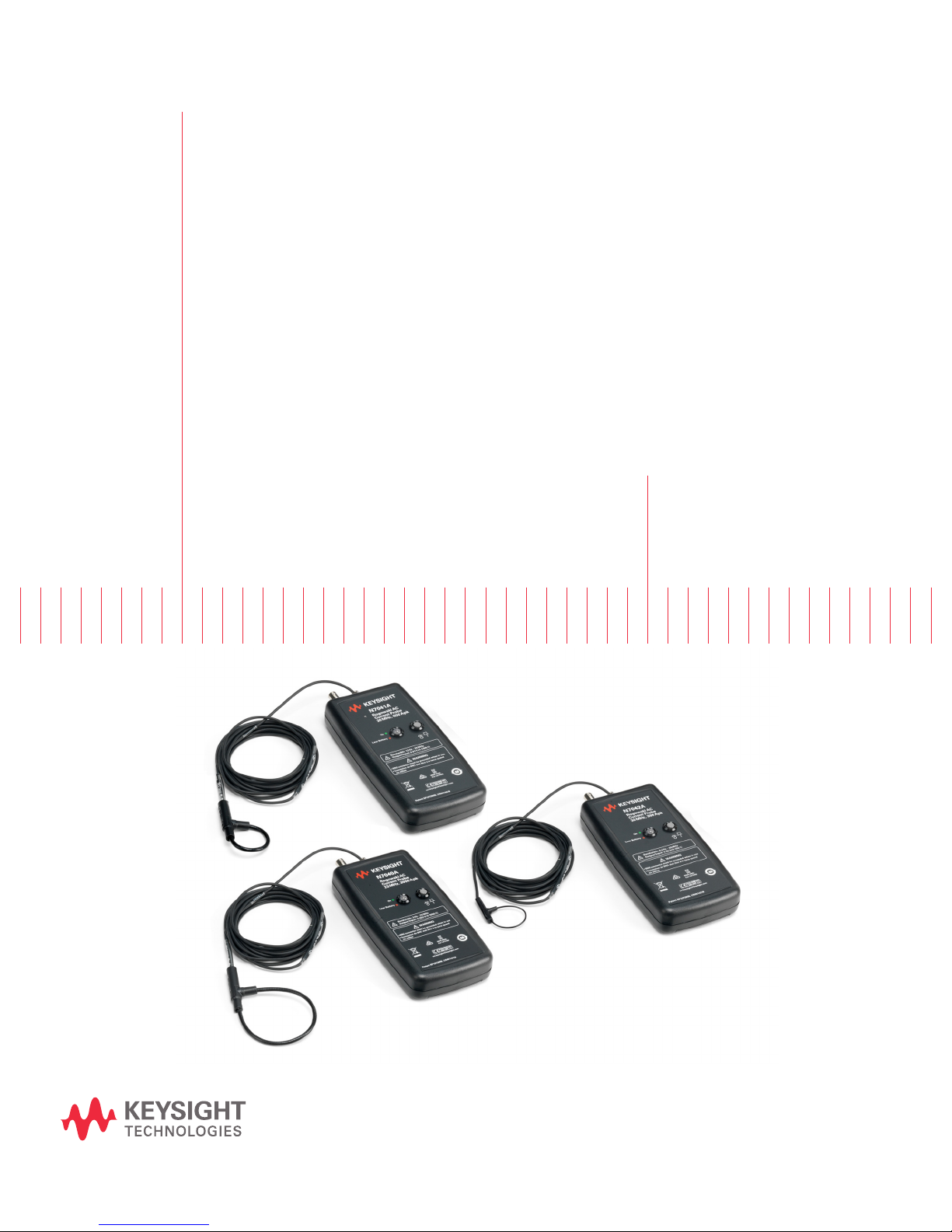
Keysight N7040A/1A/2A
Rogowski AC Current
Probes
User Guide
Page 2

Notices
CAUTION
WARNING
© Keysight Technologies 2017
No part of this manual may be reproduced in
any form or by any means (including electronic storage and retrieval or translation
into a foreign language) without prior agreement and written consent from Keysight
Technologies as governed by United States
and international copyright laws.
Manual Part Number
N7040-97000
Edition
First Edition, October 2017
Available in electronic format only
Warranty
THE MATERIAL CONTAINED IN THIS
DOCUMENT IS PROVIDED "AS IS," AND IS
SUBJECT TO BEING CHANGED, WITHOUT
NOTICE, IN FUTURE EDITIONS. FURTHER,
TO THE MAXIMUM EXTENT PERMITTED BY
APPLICABLE LAW, KEYSIGHT DISCLAIMS
ALL WARRANTIES, EITHER EXPRESS OR
IMPLIED WITH REGARD TO THIS MANUAL
AND ANY INFORMATION CONTAINED
HEREIN, INCLUDING BUT NOT LIMITED TO
THE IMPLIED WARRANTIES OF
MERCHANTABILITY AND FITNESS FOR A
PARTICULAR PURPOSE. KEYSIGHT SHALL
NOT BE LIABLE FOR ERRORS OR FOR
INCIDENTAL OR CONSEQUENTIAL
DAMAGES IN CONNECTION WITH THE
FURNISHING, USE, OR PERFORMANCE OF
THIS DOCUMENT OR ANY INFORMATION
CONTAINED HEREIN. SHOULD KEYSIGHT
AND THE USER HAVE A SEPARATE WRITTEN
AGREEMENT WITH WARRANTY TERMS
COVERING THE MATERIAL IN THIS
DOCUMENT THAT CONFLICT WITH THESE
TERMS, THE WARRANTY TERMS IN THE
SEPARATE AGREEMENT WILL CONTROL.
Technology Licenses
The hardware and/or software described in
this document are furnished under a license
and may be used or copied only in accordance with the terms of such license.
U.S. Government Rights
The Software is "commercial computer software," as defined by Federal Acquisition
Regulation ("FAR") 2.101. Pursuant to FAR
12.212 and 27.405-3 and Department of
Defense FAR Supplement ("DFARS")
227.7202, the U.S. government acquires
commercial computer software under the
same terms by which the software is customarily provided to the public. Accordingly,
Keysight provides the Software to U.S. government customers under its standard commercial license, which is embodied in its
End User License Agreement (EULA), a copy
of which can be found at http://www.key-
sight.com/find/sweula. The license set
forth in the EULA represents the exclusive
authority by which the U.S. government may
use, modify, distribute, or disclose the Software. The EULA and the license set forth
therein, does not require or permit, among
other things, that Keysight: (1) Furnish technical information related to commercial
computer software or commercial computer
software documentation that is not customarily provided to the public; or (2) Relinquish
to, or otherwise provide, the government
rights in excess of these rights customarily
provided to the public to use, modify, reproduce, release, perform, display, or disclose
commercial computer software or commercial computer software documentation. No
additional government requirements beyond
those set forth in the EULA shall apply,
except to the extent that those terms, rights,
or licenses are explicitly required from all
providers of commercial computer software
pursuant to the FAR and the DFARS and are
set forth specifically in writing elsewhere in
the EULA. Keysight shall be under no obligation to update, revise or otherwise modify
the Software. With respect to any technical
data as defined by FAR 2.101, pursuant to
FAR 12.211 and 27.404.2 and DFARS
227.7102, the U.S. government acquires no
greater than Limited Rights as defined in
FAR 27.401 or DFAR 227.7103-5 (c), as
applicable in any technical data. 52.227-14
(June 1987) or DFAR 252.227-7015 (b)(2)
(November 1995), as applicable in any technical data.
Safety Notices
A CAUTION notice denotes a hazard. It
calls attention to an operating procedure, practice, or the like that, if not
correctly performed or adhered to,
could result in damage to the product
or loss of important data. Do not proceed beyond a CAUTION notice until
the indicated conditions are fully
understood and met.
A WARNING notice denotes a hazard.
It calls attention to an operating procedure, practice, or the like that, if not
correctly performed or adhered to,
could result in personal injury or
death. Do not proceed beyond a
WARNING notice until the indicated
conditions are fully understood and
met.
2 N7040A/1A/2A Rogowski AC Current Probes User Guide
Page 3

Contents
1 N7040A/1A/2A - Overview
2 Safety and Regulatory Information
Introduction 6
Usage 8
Features 9
Specifications and Characteristics 11
Probe Dimensions 13
Inspecting the Probe 14
Cleaning the Probe 15
Probe Handling Precautions 16
Precautions while Clipping / Unclipping the Coil 16
General Coil Handling Precautions 17
Pre-Use Safety Checks and Warnings 20
Instrument Markings 22
3 Setting up and Using the Probe
Step 1 - Connect to a Compatible Keysight Oscilloscope 24
Compatibility with Oscilloscopes 24
Step 2 - Connect to a De-energized Conductor Under Test 26
Step 3 - Power Up 27
Replacing Batteries 27
Step 4 - Switch ON the Probe 28
Step 5 - Configure the Probe Settings in the Oscilloscope Software GUI 29
On an Infiniium Oscilloscope 29
On an InfiniiVision Oscilloscope 31
4 Making Measurements
Positioning the Rogowski Coil Accurately 34
Frequency Content above the Probe Bandwidth 35
Handling Probe’s Sensitivity to External Currents and Voltages 36
Choosing an Appropriate Output Cable 37
Measurements Supported 38
N7040A/1A/2A Rogowski AC Current Probes User Guide 3
Page 4

Contents
5 Returning the Probe for Repair or Service
Contacting Keysight Technologies 39
4 N7040A/1A/2A Rogowski AC Current Probes User Guide
Page 5

N7040A/1A/2A Rogowski AC Current Probes
User Guide
1 N7040A/1A/2A - Overview
Introduction / 6
Usage / 8
Features / 9
Specifications and Characteristics / 11
Inspecting the Probe / 14
Cleaning the Probe / 15
Probe Handling Precautions / 16
This chapter introduces the three models available under Keysight Rogowski AC Current probing
range and lists their features, usage, characteristics, and specifications.
Page 6
1 Overview
Rogowski Coil
Free end of
the Coil
Ferrule
Batteries
Output Cable
Connecting Cable
BNC Output
Socket
External Power
Adapter Socket
Power Button
Status Indicator
LED
Power Supply
Adapter
Introduction
The N7040A/1A/2A Rogowski AC Current probes allow you to monitor AC current flowing through a
conductor. These probes provide accurate, non-contact measurement of AC currents over a broad
frequency range thereby ensuring high bandwidth performance with minimal disruption to the circuit
under test.
These probes have a thin, lightweight, flexible, and simple to use clip-around Rogowski coil that
enables currents to be measured in the most difficult to reach parts and confined spaces of a circuit
under test. The coil size is independent of the magnitude of the current to be measured provided the
di/dt ratings for the probes are not exceeded.
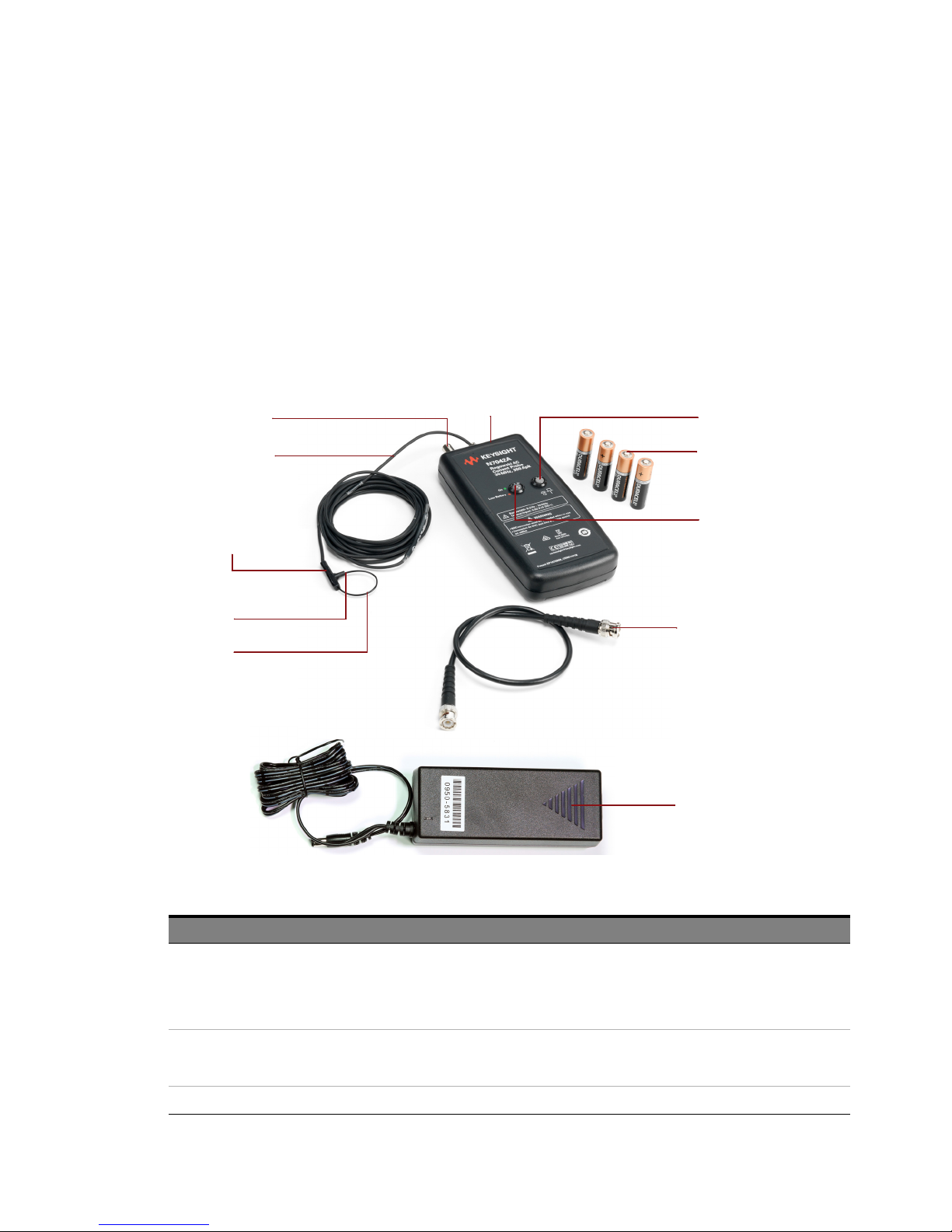
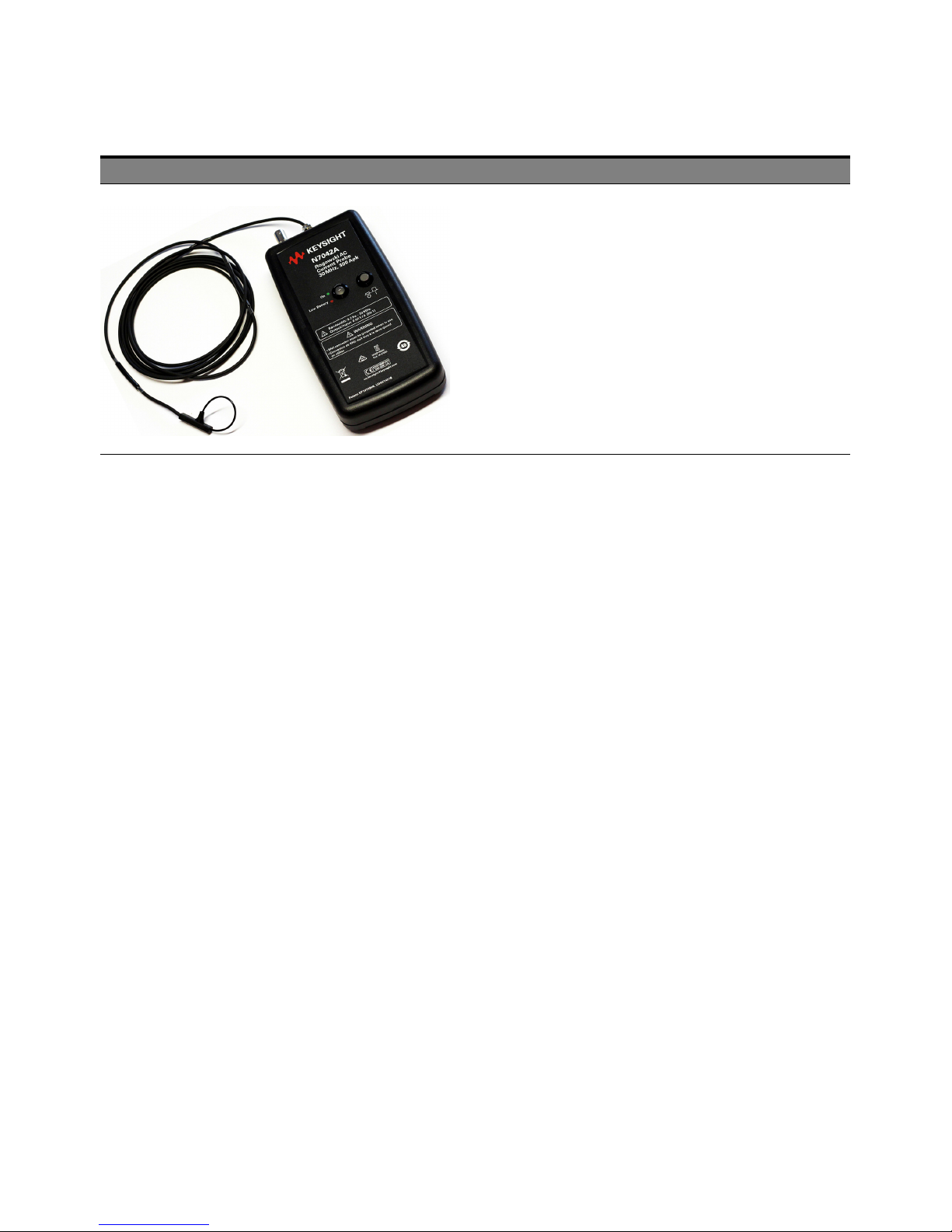
Figure 1 N7040A/1A/2A Probe Components (The figure shows the N7042A probe)
Component Description
Rogowski Coil The sensor loop of the probe that is clipped around a conductor under test. This coil is thin and delicate
Free end of the Coil Use this free end to clip / unclip the coil.
Ferrule Insert the free end of the coil into the ferrule while clipping / unclipping the coil.
6 N7040A/1A/2A Rogowski AC Current Probes User Guide
and must be handled with care. Refer to the topic “Probe Handling Precautions" on page 16 to know
more.
Refer to the Table on page 13 for the Rogowski coil’s length (circumference) and thickness applicable for
the three models.
Refer to the topic “Probe Handling Precautions" on page 16 to know about the correct insertion and
handling techniques while clipping / unclipping the coil.
Page 7
Component Description
Overview 1
Output Cable 0.5m BNC to BNC 50Ω cable to establish connectivity between the probe and oscilloscope.
Connecting Cable The cable connecting the Rogowski coil and Integrator. Refer to the Table on pag e 13 for the cable length
External Power Adapter (DC) Socket 5.5mm Jack socket to connect to an external adapter to power the probe using an external DC supply.
Power Button The push button to switch the probe ON / OFF.
Status Indicator LED The LED adjacent to the Power button to indicate the current status of the probe.
BNC Output Socket Use this socket to connect the BNC output cable to the probe.
Batteries Four standard 1.5V AA alkaline batteries. Battery Life is 25 hours (typical).
Power Supply Adapter The power supply adapter (part number 0950-5831) is also included with the probe to power the probe
In order to maintain safety, the BNC terminal must be connected to an equipment that is separated from
hazardous voltages by at least double insulation.
applicable for the three models.
Refer to the topic “Step 3 - Power Up" on page 27 to know more.
•Green - Indicates that the probe is switched ON. Also indicates that the batteries used in the probe
are charged.
•Red - Indicates that the batteries used in the probe are depleted and must be replaced.
•Off - Indicates that the probe is switched OFF.
Refer to the topic “Step 3 - Power Up" on page 27 to know more.
using an external DC supply.
Refer to the topic “Step 3 - Power Up" on page 27 to know more.
N7040A/1A/2A Rogowski AC Current Probes User Guide 7
Page 8

1 Overview
Usage
• For Power converter development and diagnostics. Following are some examples:
• In MOSFET or IGBT devices as small as TO-220 or TO-247 in case of the N7042A probe.
• In MOSFET or IGBT devices as small as TO-247 or around the terminals of large power
modules in case of the N7040A / N7041A probes.
• In bond wires in power devices
• To measure power losses in semiconductors
• To monitor currents in small inductors, capacitors, snubber circuits, etc
• To measure small AC current on a conductor with high DC current or in the presence of a high DC
magnetic field. An example can be monitoring capacitor ripple.
• To measure high frequency sinusoidal, pulsed, or transient currents from power frequency to rf
applications
• To measure current in motor drives and in particular power quality measurements in VSD, UPS or
SMPS circuits
• To evaluate switching performance of power switches (double pulse tester)
• To measure high order harmonics
8 N7040A/1A/2A Rogowski AC Current Probes User Guide
Page 9
Features
N7040A
Overview 1
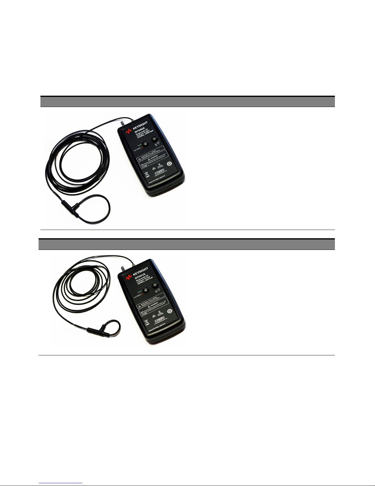
Keysight provides three models (N7040A, N7041A, and N7042A) under the Rogowski AC Current
probes. The following tables list the key features of each of these models.
• 4.5mm thick miniature clip-around Rogowski coil with 5kV peak
insulation.
• A novel electrostatic shielded Rogowski coil providing excellent immunity
to interference from fast local dV/dt transients or large 50/60Hz voltages
• Peak current rating upto 3.0kA
• -3dB high frequency bandwidth upto 23MHz
• -3dB low frequency bandwidth 3Hz
• Peak di/dt capability upto 80kA/µs
• Wide operating temperature from -40
• Terminated into 1MΩ scope input
• Positional accuracy typically ±2%
o
C to +125oC
N7041A
• 4.5mm thick miniature clip-around Rogowski coil with 5kV peak
insulation.
• A novel electrostatic shielded Rogowski coil providing excellent immunity
to interference from fast local dV/dt transients or large 50/60Hz voltages
• Peak current rating upto 0.6kA
• -3dB high frequency bandwidth upto 30MHz
• -3dB low frequency bandwidth 12Hz
• Peak di/dt capability up to 40kA/µs
• Wide operating temperature from -40
• Terminated into 1M
• Positional accuracy typically ±2%
Ω scope input
o
C to +125oC
N7040A/1A/2A Rogowski AC Current Probes User Guide 9
Page 10
1 Overview
N7042A
• 1.7mm thick ultra thin miniature clip-around Rogowski coil with 1.2kV peak
insulation.
• Peak current rating upto 300A
• -3dB high frequency bandwidth upto 30MHz
• -3dB low frequency bandwidth 9.2Hz
• Peak di/dt capabilities upto 20kA/µs
• Wide operating temperature range -40oC to +125oC
• Terminated into 1MΩ scope input
• Positional accuracy typically ±2%
• Non-intrusive and loads the circuit under test by only a few pH
10 N7040A/1A/2A Rogowski AC Current Probes User Guide
Page 11
Specifications and Characteristics
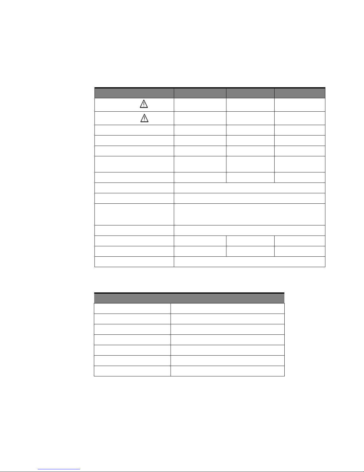
Table 1 Electrical Characteristics
Characteristic N7040A N7041A N7042A
LF (-3dB) Bandwidth 3.0 Hz 12 Hz 9.2 Hz
HF (-3dB) Bandwidth 23 MHz 30 MHz 30 MHz
Peak Current 3000 A 600 A 300 A
Droop Peak Current 2.8 %/ms 11 %/ms 9 %/ms
Peak di/dt 80kA/µs 40kA/µs 20kA/µs
Overview 1
Absolute Maximum di/dt Ratings 100kA/µs (peak) /
1.2kA/µs (rms)
Sensitivity 2mV/A (500:1) 10mV/A (100:1) 20mV/A (50:1)
Output Load >=100kohm (1Mohm scope input)
Calibration Calibrated to ±0.2% reading with conductor positioned central in the coil loop
Positional Accuracy +/-2% variation of accuracy
(Refer to the topic “Positioning the Rogowski Coil Accurately" on page 34 to know
more about how positional accuracy can help you obtain best measurements.)
Linearity ±0.05% of reading
Max Noise 8 mVp-p 10 mVp-p 15 mVp-p
Coil insulation 5kV Peak 5kV Peak 1.2kV Peak
DC Offset ±3mV maximum at 25oC
Table 2 External DC Power Supply Characteristics
Characteristic N7040A / N7041A / N7042A
DC Supply Voltage 12Vdc (+/-10%)
DC Quiescent Current 60mA @12VDC – standard alkali battery supplied with probe
DC Socket Type 5.5mm Jack Socket – Centre Positive Tip
100kA/µs (peak) /
1.2kA/µs (rms)
70kA/µs (peak) /
1.2kA/µs (rms)
Adapter Supply Voltage 100 – 240VAC
Adapter Supply Frequency 50 - 60Hz
Adapter Supply Current 450mA Max @ 100VAC Input
Supply Voltage Fluctuation up to 10%
N7040A/1A/2A Rogowski AC Current Probes User Guide 11
Page 12
1 Overview
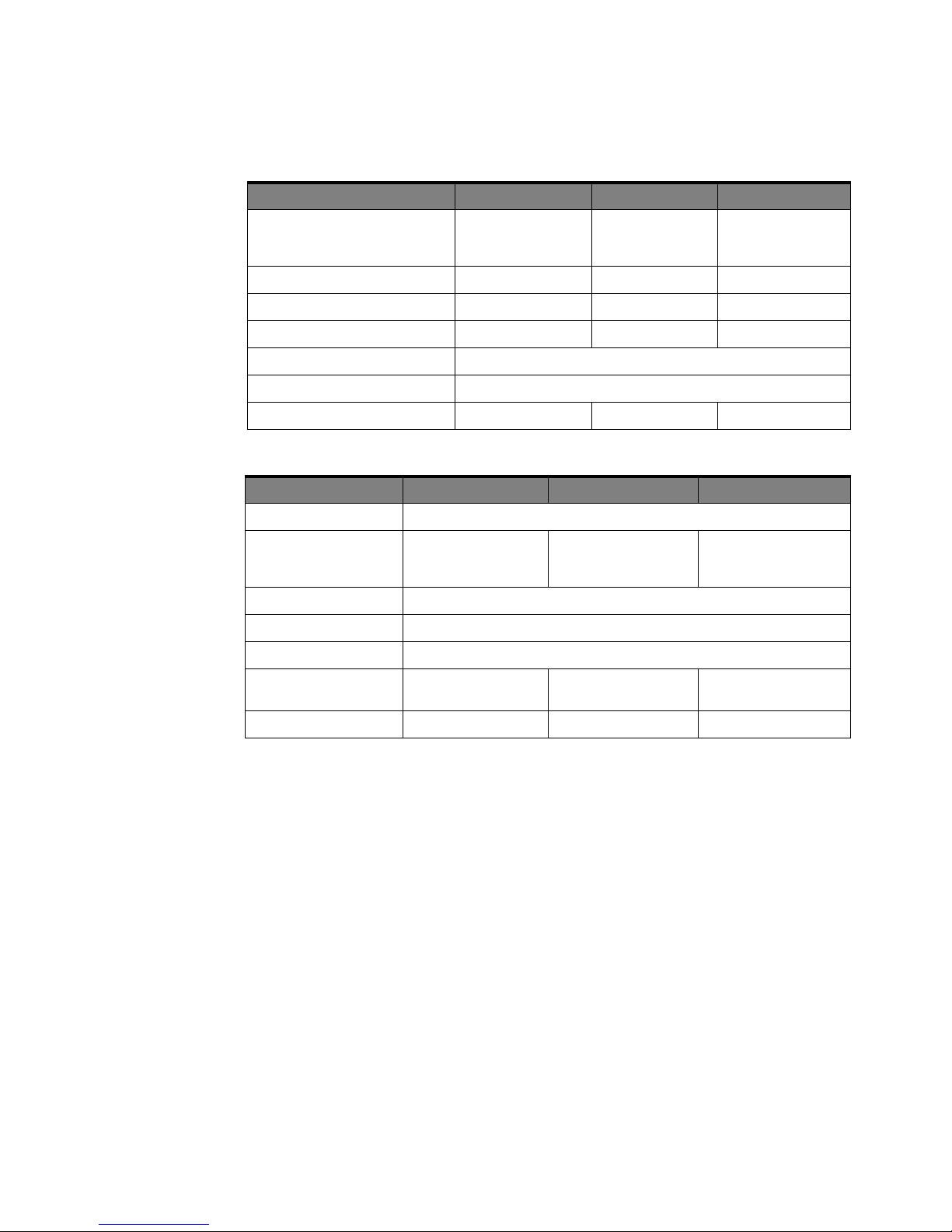
Table 3 Mechanical Characteristic
Characteristic N7040A N7041A N7042A
Weigh t
Includes Integrator, connecting cable, and
Rogowski coil (without batteries)
Rogowski Coil Length (Circumference) 200mm 100mm 80mm
Rogowski Coil Thickness 4.5mm 4.5mm 1.7mm
Coil to Integrator Cable Length 4m 2.5m 2.5m
Output BNC Cable Length 0.5m
Integrator Enclosure Dimensions Refer to “Probe Dimensions" on page 13
Minimum Bend Radius of the Coil 14mm 14mm 10mm
Table 4 Environmental Characteristics
Characteristic N7040A N7041A N7042A
Use For indoor use only
Temperature
(operating)
Altitude (operating) 4000m
Altitude (non-operating) 15000m
Maximum relative humidity 80% for temperatures up to 31°C decreasing linearly to 50% relative humidity at 40°C
Coil and Cable: -40°C to
Integrator: 0°C to +40°C
+125°C
10.8 Ounces
(306.1 g)
10.0 Ounces
(283.4 g)
Coil and Cable: -40°C to
+125°C
Integrator: 0°C to +40°C
9.6 Ounces
(272 g)
Coil and Cable: -20°C to
+125°C
Integrator: 0°C to +40°C
Installation Category Installation Category III,
Pollution Degree 2.
Overvoltage Transient Cat III 600V Cat III 600V Cat II 600V
Installation Category III,
Pollution Degree 2.
Installation Category II,
Pollution Degree 2.
12 N7040A/1A/2A Rogowski AC Current Probes User Guide
Page 13
Probe Dimensions
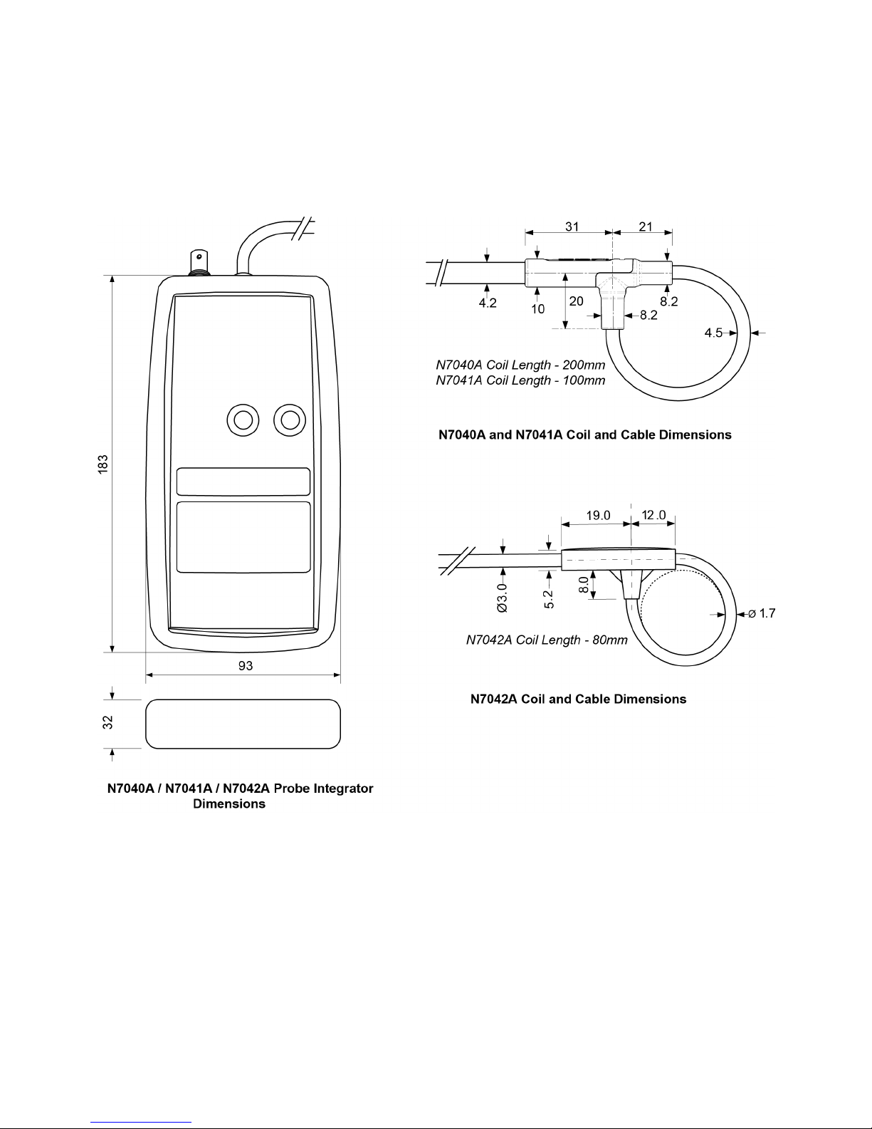
The N7040A / N7041A / N7042A probe dimensions shown below are in millimeters.
Overview 1
Refer to Tab le on page 13 to get information on mechanical characteristics of these probes.
N7040A/1A/2A Rogowski AC Current Probes User Guide 13
Page 14

1 Overview
Inspecting the Probe
• Inspect the shipping container for damage.
• Check the accessories. If the contents are incomplete or damaged, notify your Keysight
• Inspect the probe. If there is mechanical damage or defect, or if the probe does not operate
• If the shipping container is damaged, or the cushioning materials show signs of stress, notify the
Keep the damaged shipping container or cushioning material until the contents of the shipment
have been checked for completeness and the probe has been checked mechanically and
electrically.
Technologies Sales Office.
properly or pass calibration tests, notify your Keysight Technologies Sales Office.
carrier as well as your Keysight Technologies Sales Office. Keep the shipping materials for the
carrier’s inspection. The Keysight Technologies office will arrange for repair or replacement at
Keysight Technologies’ option without waiting for claim settlement.
14 N7040A/1A/2A Rogowski AC Current Probes User Guide
Page 15

Cleaning the Probe
WARNING
Overview 1
You should inspect the Rogowski coil and cable regularly to prevent any surface contamination.
If the coil or cable requires cleaning:
1 Disconnect the probe from the oscilloscope, external power supply, and any circuit under test.
2 Turn the probe OFF.
3 Gently clean the cable and coil with a soft cloth dampened with a mild soap and water solution.
4 Wipe with clean water to remove the detergent and then dry thoroughly with a clean cloth.
Do not try to clean the probe using cleaners containing organic solvents such
as benzine, alcohol, acetone, ether, ketones, thinners, or gasoline. These may
cause discoloration or damage. Make sure the probe is completely dry before
reconnecting it for use.
N7040A/1A/2A Rogowski AC Current Probes User Guide 15
Page 16
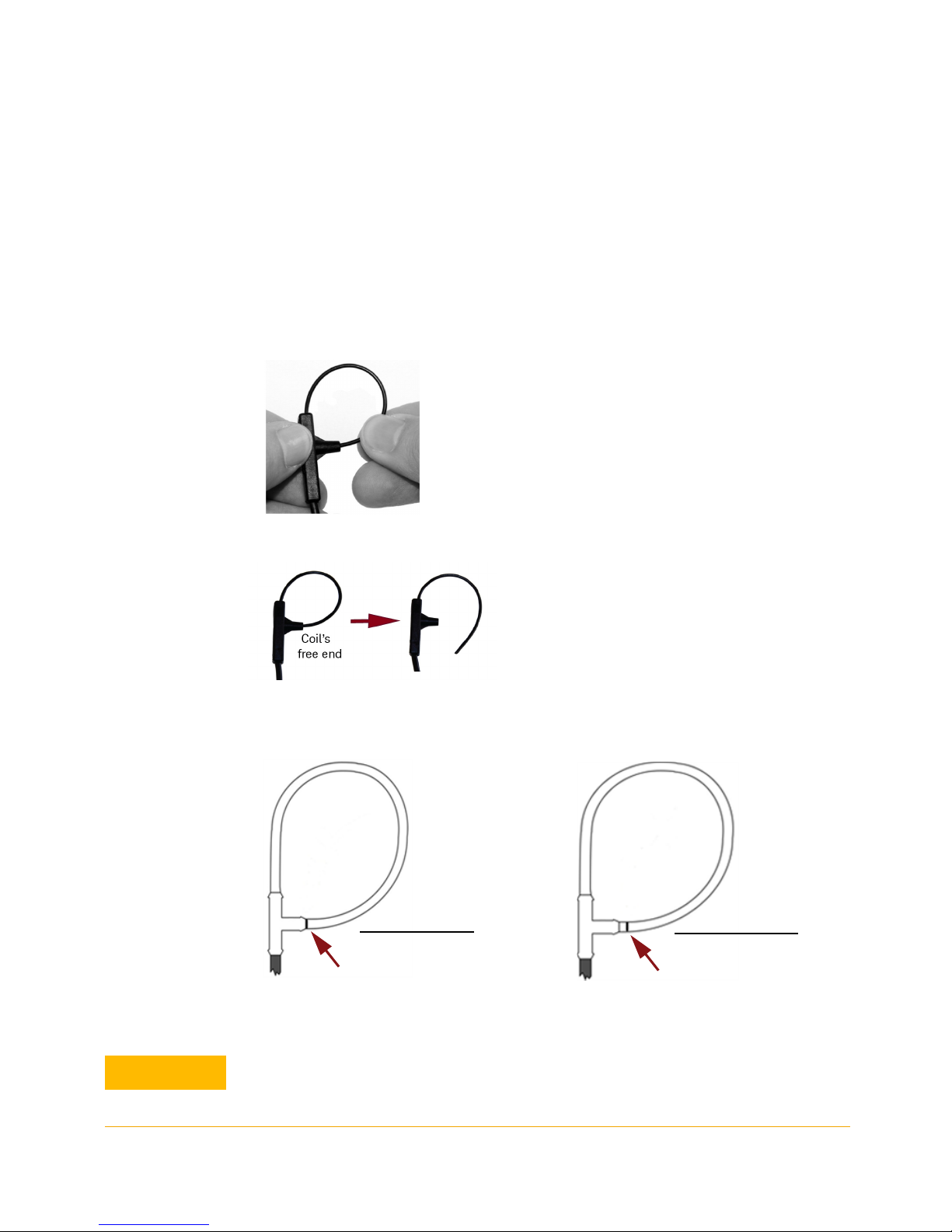
1 Overview
Incorrect Coil Insertion
Marker line on the coil is
visible outside the ferrule
Correct Coil Insertion
Coil is inserted into the ferrule upto
the black marker line on the free
end of the coil
CAUTION
Probe Handling Precautions
The extremely thin and flexible qualities of the Rogowski coil makes it delicate and fragile and
necessitates that it should be handled with care to prolong its life. The following sections provide
instructions for proper handling of the coil and list some precautions that should be taken to avoid
damage to the coil.
Precautions while Clipping / Unclipping the Coil
• Hold the probe’s ferrule as shown in the picture below while clipping / unclipping the coil.
• Unclip the coil from its free end as shown in the picture below.
• For the N7040A / N7041A probes, ensure that the coil is correctly and fully inserted inside the
probe’s ferrule as illustrated in the figure below.
• For the N7042A probe, the coil has a friction fit. It is considered fully inserted into the ferrule when
you can no further ease the coil’s free end into the ferrule.
If the coil is inserted correctly inside the ferrule, the coil will remain in place until released.
If the coil is inserted incorrectly, the coil is likely to spring open while in use. Also, the
accuracy of measurements will be greatly impacted.
16 N7040A/1A/2A Rogowski AC Current Probes User Guide
Page 17
General Coil Handling Precautions
CAUTION
CAUTION
NOTE
Overview 1
- Never force the free end of the coil into the ferrule. This may damage the
coil insulation.
- Take care not to put any force onto the cable attached to the coil. This may
damage the coil.
While bending the coil around a conductor, keep the minimum bend radius
of the coil into consideration to avoid damage to the coil.
N7040A - 14 mm
N7041A - 14 mm
N7042A - 10 mm
It is recommended to store the coil in its protective case when not in use.
N7040A/1A/2A Rogowski AC Current Probes User Guide 17
Page 18

1 Overview
18 N7040A/1A/2A Rogowski AC Current Probes User Guide
Page 19

N7040A/1A/2A Rogowski AC Current Probes
User Guide
2 Safety and Regulatory Infor-
mation
Pre-Use Safety Checks and Warnings / 20
Instrument Markings / 22
These probes have been designed and tested in accordance with accepted industry standards, and have
been supplied in a safe condition. These probes conform to international standards including IEC
61010-1 and IEC 61010-2-032.
Throughout this manual and specifically in this chapter, there are information and warnings that must be
followed by the user to ensure safe operation and to maintain the product in a safe condition. If the probe
is used in a manner not specified by the manufacturer, the protection provided by the equipment may be
impaired.
Page 20
2 Safety and Regulatory Information
WARNING
CAUTION
WARNING
WARNING
WARNING
WARNING
Pre-Use Safety Checks and Warnings
Indoor Use Only. Do not operate in wet / damp environments. Keep product
surfaces dry and clean.
Do not operate in an explosive environment.
The intended use of these probes is for the measurement of AC current.
Keysight Technologies accepts no responsibility for any damage resulting
from careless use, or failure to observe these instructions.
If HAZARDOUS LIVE voltages are present and accessible in the installation,
appropriate protective measures must be taken to avoid electric shock.
The integrity of the insulation around the Rogowski coil must be VISUALLY
INSPECTED before and after each use, and the probe must NOT BE USED if
there are signs of coil damage.
Be extremely careful when using the coil of the probe on uninsulated
conductors. The power of the uninsulated conductor must be turned off
when applying or removing the probe’s coil from this conductor.
In addition, make sure that the probe is never used at voltages greater than
its voltage rating (safe PEAK working voltage) which is clearly labeled on
the probe cable adjacent to the coil. For N7040A and N7041A, it is 5kV peak
and for N7042A, it is 1.2kV peak.
Voltage ratings are only valid if the ‘free end’ of the coil is fully inserted into
the probe’s ferule, and remains fully inserted during use. Refer to the topic
“Probe Handling Precautions" on page 16 to know more.
20 N7040A/1A/2A Rogowski AC Current Probes User Guide
Page 21
Safety and Regulatory Information 2
WARNING
CAUTION
WARNING
CAUTION
The voltage ratings are appropriate for intermittent use of the probe as a
test instrument and not for continuous use in a permanent installation.
The ratings are derived from the following standard test:
- N7042A coil (rated for 1.2kV peak) is flash tested for one minute at
3.0kVrms using a 50Hz sine-wave voltage.
- N7040A and N7041A coils (rated for 5kV peak) are flash tested for one
minute at 8kVrms using a 50Hz sine-wave voltage.
Though these probes are capable of handling huge current overloads
without damaging or saturating the probes, it is crucial that the absolute
maximum rated di/dt for the probe is not exceeded. Refer to the Table on
page 13 to know these ratings.
These probes and the oscilloscope must be properly grounded when used.
Making the connection between the oscilloscope and probe using the BNC
cable grounds the BNC input for the probe.
Properly connecting the oscilloscope’s three prong power cord to the power
outlet grounds the oscilloscope. See the oscilloscope user manual for more
information on proper oscilloscope grounding.
Ensure that the signals are within the LF and HF Bandwidth range of the
probes. Refer to the Table on page 13 to know about the supported
bandwidth range for your probe.
N7040A/1A/2A Rogowski AC Current Probes User Guide 21
Page 22
2 Safety and Regulatory Information
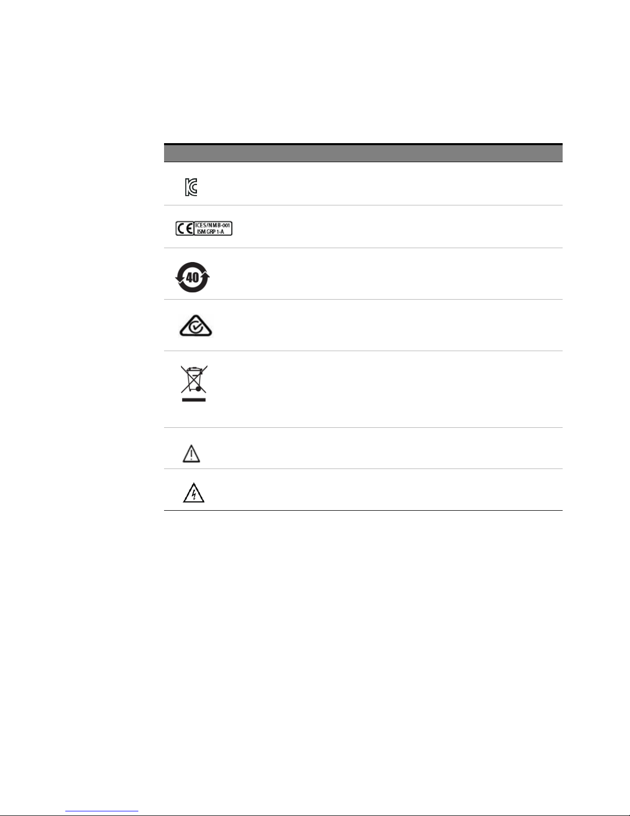
Instrument Markings
Marking Description
KC certification mark to demonstrate compliance with the South Korean EMC requirements.
South Korean Class A EMC declaration This equipment is Class A suitable for professional use and is for
use in electromagnetic environments outside of the home.
The CE mark is a registered trademark of the European Community. ISM GRP 1-A denotes the instrument
is an Industrial Scientific and Medical Group 1 Class A product. ICES/NMB-001 indicates product
compliance with the Canadian Interference-Causing Equipment Standard.
This symbol indicates the Environmental Protection Use Period (EPUP) for the product’s toxic substances
for the China RoHS requirements.
A registered trademark of the Spectrum Management Agency of Australia. This signifies compliance with
the Australia EMC Framework regulations under the terms of the Radio Communication Act of 1992.
Notice for the European Community: This product complies with the WEEE Directive (2002/96/EC)
marking requirements. The affixed label indicates that you must not discard this electrical/electronic
product in domestic household waste.
Product Category: With reference to the requirement types in the WEEE Directive Annex I, this product is
classed as a “Monitoring and Control Instrumentation” product.
Do not dispose in domestic household waste.
To return unwanted products, contact your local Keysight office.
The product is marked with this symbol when it is necessary for the user to refer to the instructions in the
documentation.
This symbol indicates a risk of electric shock. Refer to this manual for more information.
22 N7040A/1A/2A Rogowski AC Current Probes User Guide
Page 23

N7040A/1A/2A Rogowski AC Current Probes
User Guide
3 Setting up and Using the
Probe
Step 1 - Connect to a Compatible Keysight Oscilloscope / 24
Step 2 - Connect to a De-energized Conductor Under Test / 26
Step 3 - Power Up / 27
Step 4 - Switch ON the Probe / 28
Step 5 - Configure the Probe Settings in the Oscilloscope Software GUI / 29
Page 24
3 Overview
NOTE
WARNING
Step 1 - Connect to a Compatible Keysight Oscilloscope
Compatibility with Oscilloscopes
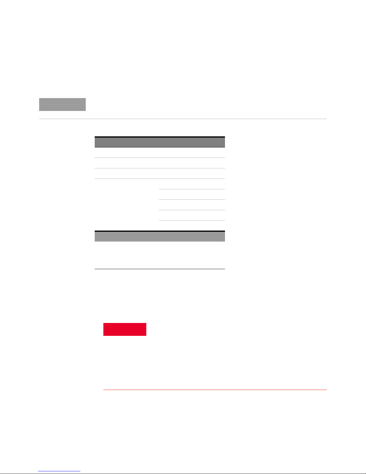
You can use these probes with any Keysight Infiniium or InfiniiVision oscilloscope that has the
1MΩ BNC input.
Infiniium Oscilloscopes InfiniiVision Oscilloscopes
S-Series 6000L Series
9000 Series 6000 X-Series
9000 H-Series 4000 X Series
3000 X Series
3000T X Series
2000 X Series
1000 X Series
1000 Series
Infiniium Software Version InfiniiVision Software Version
Compatible with all Infiniium
software versions
Recommended version: 6.10 or
higher
Compatible with all InfiniiVision
software versions
To connect to a compatible Keysight oscilloscope
Before you start setting up the probe, ensure that all safety warnings and precautions listed in the
topic “Pre-Use Safety Checks and Warnings" on page 20 and 19 are followed.
1 Connect the probe’s BNC output connector to the oscilloscope’s BNC input connector using the
BNC cable provided with the probe.
Grounding is critical to the safe operation of the probe. This connection
using the BNC cable grounds the probe and coil to a properly grounded
oscilloscope.
This connection must always be made BEFORE the coil is wrapped
around the conductor under test and must not be removed until the coil
has been removed from around the conductor under test.
Extreme caution needs to be taken not to damage coil insulation when
placing or removing coil around sharp conductors.
24 N7040A/1A/2A Rogowski AC Current Probes User Guide
Page 25

Overview 3
CAUTION
When disconnecting the BNC cable from the oscilloscope, be sure to
release the lock, then pull the connector. Forcibly pulling the connector
without releasing the lock, or pulling on the cable will result in damage to
the connector.
N7040A/1A/2A Rogowski AC Current Probes User Guide 25
Page 26
3 Overview
WARNING
CAUTION
Step 2 - Connect to a De-energized Conductor Under Test
Visually inspect the Rogowski coil to check for the integrity of the
insulation around the coil. The probe must NOT BE USED if there are any
signs of damage.
1 Unclip the coil from its free end as described in the “Probe Handling Precautions" on page 16.
2 Make a loop of the Rogowski coil around the de-energized conductor to be measured.
When bending the Rogowski coil around a conductor, avoid tight bends
and sharp edges that could damage the coil.
See Table 3 on page 12 for information on minimum bend radius for the
coil.
The positioning of the coil around the conductor can impact the accuracy of your measurements.
Refer to the topic “Positioning the Rogowski Coil Accurately" on page 34 to know more.
3 Insert the free end of the coil fully inside the probe’s ferrule as described in the “Probe Handling
Precautions" on page 16. Ensure that the loop is closed properly.
4 Re-energize the conductor under test.
26 N7040A/1A/2A Rogowski AC Current Probes User Guide
Page 27
Step 3 - Power Up
CAUTION
CAUTION
NOTE
NOTE
Overview 3
Before applying power, ensure that all connections to the probe have been
made. Also, verify that all safety precautions have been taken.
You can power up the N7040A/41A/42A probes by using:
• External DC power supply - The DC voltage must be 12V (±10%).
The external power supply adapter (Keysight part number - 0950-5831)
provided with the probe must be used.
• Batteries - Four standard 1.5V alkaline AA batteries provided with the probe.
When the external DC supply is present, the batteries are inoperative and
the external DC voltage powers the probe.
When operating with the external power supply adapter, refer to Table 2, “External DC Power Supply
Characteristics,”
Replacing Batteries
The Status Indicator LED adjacent to the Power button on the probe glows Red indicating low
battery. To replace the battery, switch off the probe, remove the battery cover, and replace with
standard AA alkaline batteries.
It is recommended that the circuit under test is de-energised or the probe is
removed from the test circuit before replacing the batteries.
N7040A/1A/2A Rogowski AC Current Probes User Guide 27
Page 28
3 Overview
NOTE
Step 4 - Switch ON the Probe
1 Use the Power push-button on the probe to switch OFF/ON the probe by pressing and releasing
this button. The Status LED adjacent to the Power button turns Green indicating that the probe is
switched ON.
2 To switch OFF the probe, depress the Power button fully.
After you switch ON the probe, wait for upto 2 minutes before you start
making any measurements. This is to allow the probe to warm up so that
accurate measurements can be taken.
28 N7040A/1A/2A Rogowski AC Current Probes User Guide
Page 29
Step 5 - Configure the Probe Settings in the Oscilloscope Software GUI
After making hardware connections, perform the following steps in the Infiniium / InfiniiVision
Oscilloscope software GUI to configure probe settings such as identifying the type of probe attached
to the oscilloscope and setting the appropriate input impedance and attenuation ratio etc. These
settings are required to get accurate measurement results.
On an Infiniium Oscilloscope
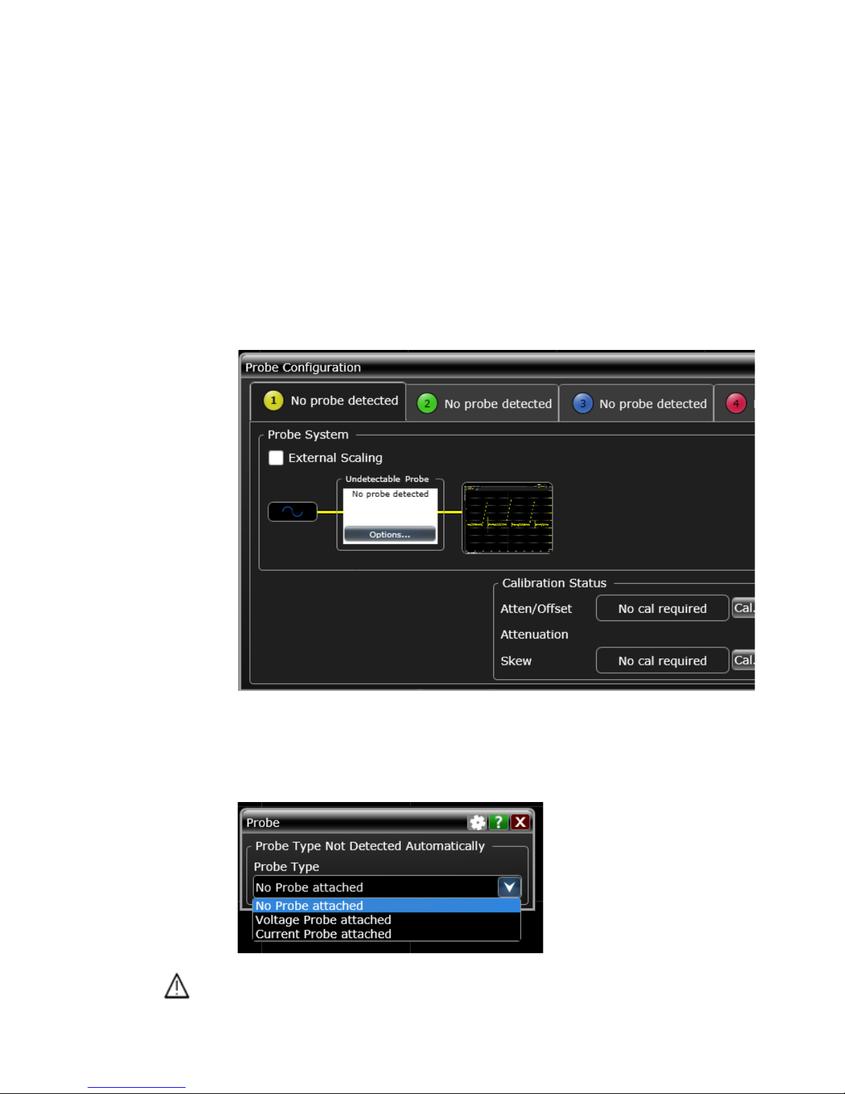
1Choose Setup > Probe Configuration... to open the Probe Configuration dialog box. The
N7040A/41A/42A probe is not automatically identified by the oscilloscope and therefore not
displayed as connected to the scope’s channel.
Overview 3
2 To manually identify the type of probe and configure its settings, click Options... displayed in the
Probe System section of the scope channel to which the current probe is connected. In the above
screen, the settings for the N7042A probe connected to Channel 1 are being configured.
3The Probe dialog box is displayed. Select the Current Probe attached option from the Probe Type
drop-down listbox.
4From the Current Probe drop-down listbox, select the attenuation ratio for your current probe to
match the Output/Input ratio (in V/A) (printed on the label on the front side of the probe).
N7040A/1A/2A Rogowski AC Current Probes User Guide 29
Page 30
3 Overview
• N7040A.................... 0.002 V/A (500:1)
• N7041A.....................0.01 V/A (100:1)
• N7042A.................... 0.02 V/A (50:1)
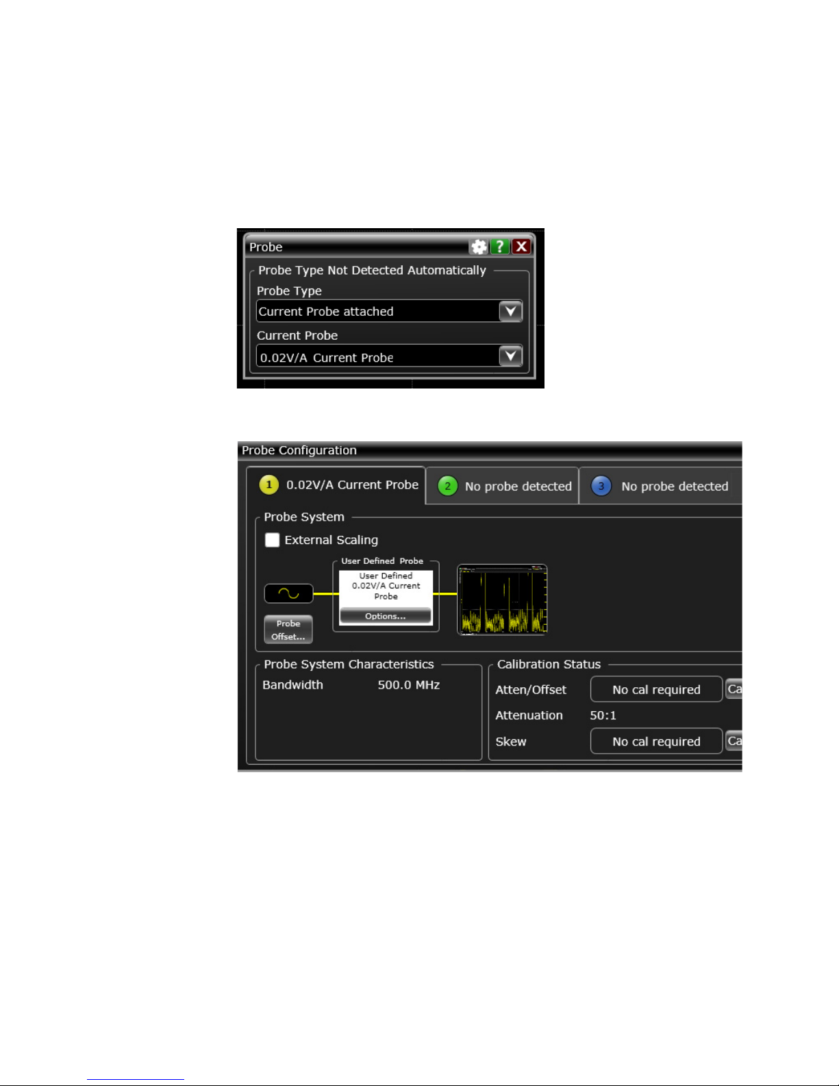
In the example below, the 0.02 V/A has been selected for the N7042A probe.
On identifying the probe type, the current probe is now displayed in the Probe configuration
dialog box.
5 Configure the scope channel settings to which the current probe is attached. To do so, access the
Channel dialog box by clicking Setup > Channel <N> option from the menu on the top.
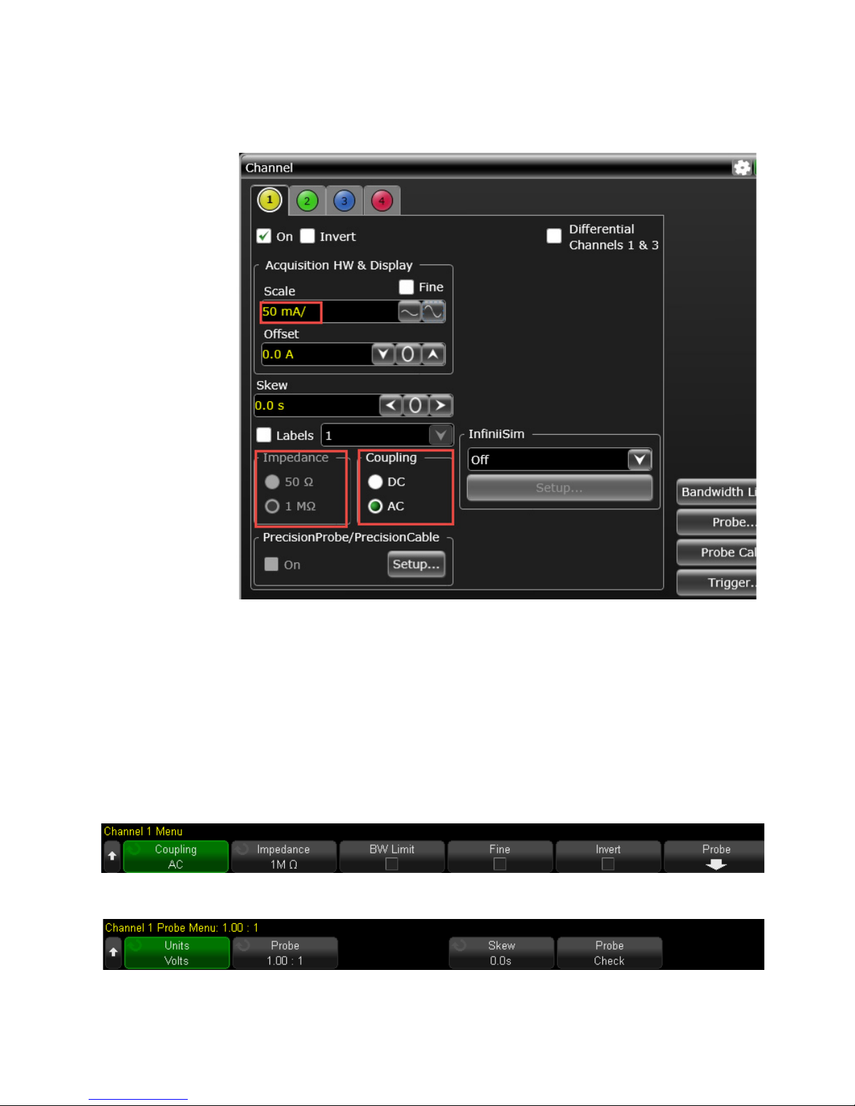
6 In the Channel dialog box, confirm that the following settings are configured correctly for the
channel.
• The Vertical scale unit of the oscilloscope should be set to Amps. In the Scale field, select the
desired Amps per division scale for a waveform.
•The Input Impedance of the oscilloscope channel must be set to 1 MΩ to make accurate
measurements.
• Set the oscilloscope’s Input Coupling to AC to remove any DC offset voltage from the waveform.
These settings are highlighted in the following screen.
30 N7040A/1A/2A Rogowski AC Current Probes User Guide
Page 31
Overview 3
7 Measure the current and observe the waveform on the oscilloscope. Remember that the actual
current will be greater or less than the oscilloscope waveform if the probe attenuation has not
been set accurately.
On an InfiniiVision Oscilloscope
The N7040A/41A/42A probe is not automatically identified by the oscilloscope and therefore you
need to manually set the attenuation factor and units for the probe.
1 Press the channel key to which the current probe is attached to display the Channel <N> menu.
2 Press the Coupling softkey to set the oscilloscope’s Input Coupling to AC to remove any DC offset
voltage from the waveform.
3 Press the Impedance softkey to set the input impedance of the oscilloscope channel to 1 MΩ to
make accurate measurements.
4 Press the Probe softkey to display the channel’s probe menu.
5 Press the Units softkey to select Amps as the measurement unit for the connected probe.
N7040A/1A/2A Rogowski AC Current Probes User Guide 31
Page 32
3 Overview
6 Press the Probe softkey until you have selected how you want to specify the attenuation factor,
choosing either Ratio or Decibels.
7 Rotate the Entry knob to set the attenuation factor for your current probe. The attenuation
factor must match the Output/Input ratio (in V/A) (printed on the label on the front side of the
probe).
• N7040A.................... 0.002 V/A (500:1)
• N7041A.....................0.01 V/A (100:1)
• N7042A.................... 0.02 V/A (50:1)
8 Measure the current and observe the waveform on the oscilloscope. Remember that the actual
current will be greater or less than the oscilloscope waveform if the probe attenuation has not
been set accurately.
32 N7040A/1A/2A Rogowski AC Current Probes User Guide
Page 33

N7040A/1A/2A Rogowski AC Current Probes
User Guide
4 Making Measurements
Positioning the Rogowski Coil Accurately / 34
Frequency Content above the Probe Bandwidth / 35
Handling Probe’s Sensitivity to External Currents and Voltages / 36
Choosing an Appropriate Output Cable / 37
Measurements Supported / 38
This chapter provides guidelines that you would find useful in obtaining the best measurements accuracy
using the N7040A/41A/42A probes. It also provides an overview of some relevant measurements that you
can make using these probes on a compatible Keysight oscilloscope.
Page 34
4 Overview
Positioning the Rogowski Coil Accurately
You can achieve the maximum accuracy in your measurement results by ensuring that the Rogowski
coil is positioned properly around the conductor under test.
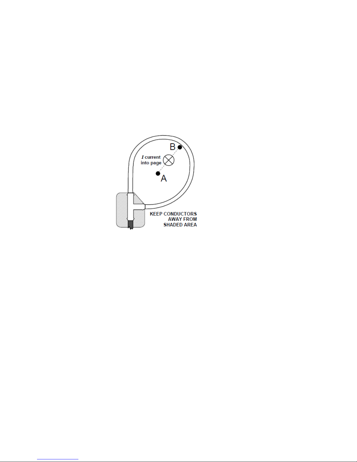
• Position the Rogowski coil in such a manner that the conductor under test is encircled by the coil
but is not adjacent to the ferrule or the probe cable attachment as illustrated by the shaded area
in the picture below.
• The N7040A/41A/42A probes have been calibrated with the conductor near the center (indicated
by position A in the picture below).
• The picture also shows the direction a positive current should pass through the coil loop to obtain
a positive output voltage. For the best high frequency performance, the center of the current
should lie on the dotted line shown from A to B, where A represents the center of the coil and B
represents half way around the circumference of the coil.
34 N7040A/1A/2A Rogowski AC Current Probes User Guide
Page 35

Frequency Content above the Probe Bandwidth
Attempting to make measures on signal sources which include higher frequency components will
result in measurement accuracy issues. To make the most accurate measurements, the signals to be
measured should not have frequency content above the probe’s bandwidth and should have rise
times greater than 20 ns.
Overview 4
N7040A/1A/2A Rogowski AC Current Probes User Guide 35
Page 36

4 Overview
Handling Probe’s Sensitivity to External Currents and Voltages
The sensitivity of the N7040A/41A/42A probes to currents that are outside the closed loop of the
Rogowski coil is very small, provided that the external currents are less than the current rating of the
probe or that such currents are relatively distant from the coil.
Following are some of the recommendations to handle probe’s sensitivity to external currents and
voltages.
• In the vicinity of a multi-turn conductor, the effects are far stronger than from a single conductor
carrying the same current, and such positions should be avoided.
• If there is a surface with a high voltage very close to the coil and the voltage is subject to high
rates of change (for example, 1kV/ìs) or high frequency oscillations in the MHz range, then
measurement errors can arise due to capacitive coupling to the coil.
• To check for any unwanted response to adjacent fields, it is recommended to quantify the output
of the probe when close to (but not encircling) the conductor under test. This will reveal the
magnitude of any unwanted responses to currents close to, but outside, the coil.
36 N7040A/1A/2A Rogowski AC Current Probes User Guide
Page 37

Choosing an Appropriate Output Cable
The N7040A/41A/42A probes are shipped with a 0.5m BNC to BNC 50 Ω cable to establish
connectivity between the probe and oscilloscope.
If needed, you may use a longer cable that meets the requirement of a 50 Ω single screened coaxial
cable type.
Also, though the use of extension cables may not be problematic from the noise viewpoint but
consideration should be given to the routing of very long cables.
Overview 4
N7040A/1A/2A Rogowski AC Current Probes User Guide 37
Page 38
4 Overview
NOTE
Measurements Supported
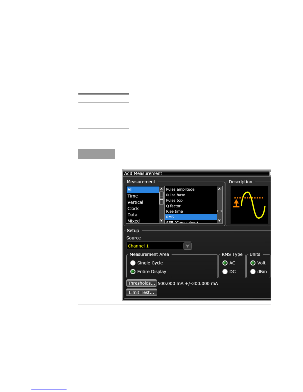
There are a number of measurements available in the Infiniium / InfiniiVision GUI that are relevant for
AC current measurement using these probes. Some of these measurements are listed below. You
can find a detailed description of each of the supported measurement in the online help for the
Infiniium / InfiniiVision GUI.
Peak
Peak-Peak Contrast
RMS
Rise Time
Frequency
For measurements such as RMS, there are two types available - AC and DC.
Ensure that you select the type as AC for such measurements.
38 N7040A/1A/2A Rogowski AC Current Probes User Guide
Page 39

N7040A/1A/2A Rogowski AC Current Probes
WARNING
User Guide
5 Returning the Probe for Repair
or Service
If the probe is found to be defective, it is recommended to send it to a Keysight authorized service
center for all repair and service needs.
If the probe is under warranty, normal warranty services apply. If the probe is not under warranty,
repair costs will be applied.
Do not install substitute parts or perform any unauthorized modification to
the instrument.
Only Keysight service centers should perform repair/maintenance on the
equipment.
Only Keysight approved accessories should be used.
Perform the following steps before shipping the probe back to Keysight Technologies for repair /
service.
1 Contact your nearest Keysight sales office for any additional details.
2 Write the following information on a tag and attach it to the malfunctioning equipment.
• Name and address of owner
• Product model number (for example, N7040A)
• Product Serial Number (for example, MYXXXXXXXX)
• Description of failure or service required
3 Protect the probe by wrapping in plastic or heavy paper. Use original packaging or comparable.
4 Pack the probe in the original carrying case or if not available, use bubble wrap or packing
peanuts.
5 Place securely in sealed shipping container and mark container as "FRAGILE".
If any correspondence is required, refer to the product by serial number and model number.
Contacting Keysight Technologies
For technical assistance, contact your local Keysight Call Center.
• In the Americas, call 1 (800) 829-4444
• In other regions, visit http://www.keysight.com/find/assist
Before returning an instrument for service, you must first call the Call Center.
Page 40

5 Returning the N7004A for Repair or Service
40 N7040A/1A/2A Rogowski AC Current Probes User Guide
Page 41

N7040A/1A/2A Rogowski AC Current Probes User Guide 41
Page 42
This information is subject to
change without notice.
© Keysight Technologies 2017
Edition 1, October 2017
N7040-97000
www.keysight.com
 Loading...