

Page 1
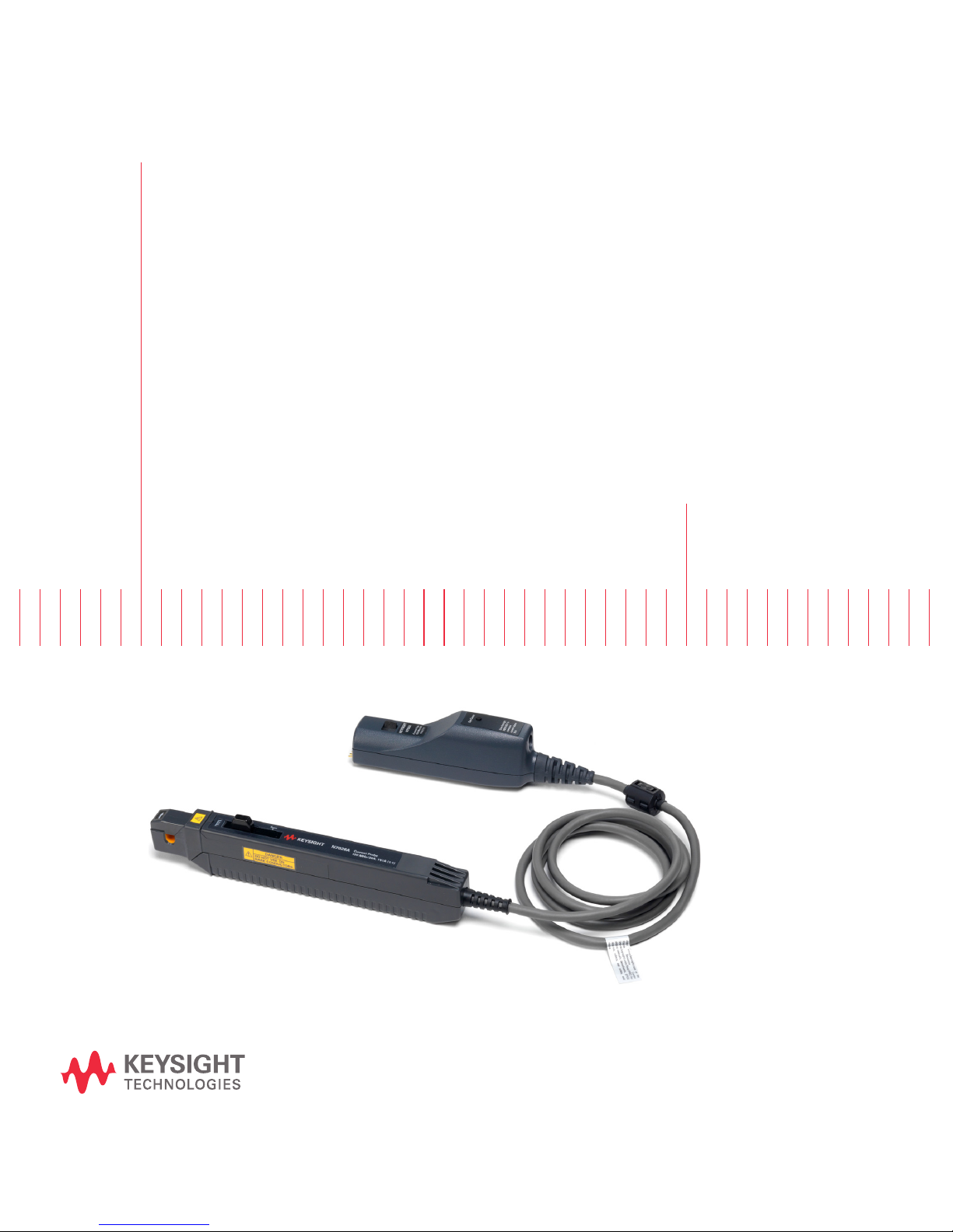
Keysight N7026A 150 MHz
AC/DC High Sensitivity
Current Probes
User’s
Guide
Page 2
Notices
CAUTION
WARNING
DANGER
© Keysight Technologies, Inc. 2017, 2018
No part of this manual may be reproduced in
any form or by any means (including electronic storage and retrieval or translation into
a foreign language) without prior agreement
and written consent from Keysight Technologies, Inc. as governed by United States and
international copyright laws.
Manual Part Number
N7026-97001
Edition
Second Edition, July 2018
Published by:
Keysight Technologies, Inc.
1400 Fountaingrove Parkway
Santa Rosa, CA, 95403
Warranty
The material contained in this document is
provided “as is,” and is subject to being
changed, without notice, in future editions.
Further, to the maximum extent permitted
by applicable law, Keysight disclaims all
warranties, either express or implied, with
regard to this manual and any information
contained herein, including but not limited
to the implied warranties of merchantability
and fitness for a particular purpose. Keysight shall not be liable for errors or for incidental or consequential damages in
connection with the furnishing, use, or performance of this document or of any information contained herein. Should Keysight
and the user have a separate written agreement with warranty terms covering the
material in this document that conflict with
these terms, the warranty terms in the separate agreement shall control.
Technology Licenses
The hardware and/or software described in
this document are furnished under a license
and may be used or copied only in accordance with the terms of such license.
U.S. Government Rights
The Software is "commercial computer software," as defined by Federal Acquisition Regulation ("FAR") 2.101. Pursuant to FAR
12.212 and 27.405-3 and Department of
Defense FAR Supplement ("DFARS")
227.7202, the U.S. government acquires
commercial computer software under the
same terms by which the software is customarily provided to the public. Accordingly,
Keysight provides the Software to U.S. government customers under its standard commercial license, which is embodied in its End
User License Agreement (EULA), a copy of
which can be found at
sight.com/find/sweula
forth in the EULA represents the exclusive
authority by which the U.S. government may
use, modify, distribute, or disclose the Software. The EULA and the license set forth
therein, does not require or permit, among
other things, that Keysight: (1) Furnish technical information related to commercial computer software or commercial computer
software documentation that is not customarily provided to the public; or (2) Relinquish
to, or otherwise provide, the government
rights in excess of these rights customarily
provided to the public to use, modify, reproduce, release, perform, display, or disclose
commercial computer software or commercial computer software documentation. No
additional government requirements beyond
those set forth in the EULA shall apply, except
to the extent that those terms, rights, or
licenses are explicitly required from all providers of commercial computer software pursuant to the FAR and the DFARS and are set
forth specifically in writing elsewhere in the
EULA. Keysight shall be under no obligation
to update, revise or otherwise modify the
Software. With respect to any technical data
http://www.key-
. The license set
as defined by FAR 2.101, pursuant to FAR
12.211 and 27.404.2 and DFARS 227.7102,
the U.S. government acquires no greater than
Limited Rights as defined in FAR 27.401 or
DFAR 227.7103-5 (c), as applicable in any
technical data.
Safety Notices
A CAUTION notice denotes a hazard. It
calls attention to an operating procedure, practice, or the like that, if not
correctly performed or adhered to, could
result in damage to the product or loss
of important data. Do not proceed
beyond a CAUTION notice until the indicated conditions are fully understood
and met.
A WARNING notice denotes a hazard. It
calls attention to an operating procedure, practice, or the like that, if not
correctly performed or adhered to,
could result in personal injury or death.
Do not proceed beyond a WARNING
notice until the indicated conditions
are fully understood and met.
A DANGER notice that incorrect operation presents extreme danger of accident resulting in death or serious injury
to the user.
2 N7026A 150 MHz AC/DC High Sensitivity Current Probes User Guide
Page 3

Contents
Introduction / 5
AutoProbe Interface / 5
External Power Supply / 5
Operating Modes / 5
Auto Demagnetization (Degauss) and Calibration / 5
N7026A Kit Components / 7
Characteristics and Specifications / 10
Compatibility with Oscilloscopes / 12
Inspecting the Probe / 13
Cleaning the Probe / 14
Cleaning the Sensor Head / 14
Safety Information / 15
Powering the Probe / 17
Using the External DC Power Supply / 17
N7026A 150 MHz AC/DC High Sensitivity Current Probes User Guide 3
Setting up the Probe / 19
Obtaining the Best Measurement Accuracy / 23
Installing and Removing Bushing / 24
Performing Demagnetization and Zero Offset / 26
Protecting the Probe Against Damage Resulting from Excessive
Input / 28
Built-in Safety Function / 28
Performance Verification for N7026A / 30
Procedure / 30
Plots / 35
Page 4

Contents
Product Markings and Labels / 38
Service Strategy / 39
To return the Probe to Keysight Technologies for Service / 39
Index
4 N7026A 150 MHz AC/DC High Sensitivity Current Probes User’s Guide
Page 5

Introduction
AutoProbe Interface
N7026A 150 MHz AC/DC High Sensitivity Current Probes
User’s Guide
The N7026A is a wide-band, DC to 150 MHz, clamp-on active current probe. It is ideal for
acquiring high transient time signals such as those found in motor controllers, in switching
power supplies, and in current amplifiers driving inductive loads.
This high bandwidth, high sensitivity (1V/A), and low noise probe enables you to achieve a
high degree of precision even while measuring very low-current waveforms.
The following sections briefly describe the key features of this probe.
The probe’s output connector has the AutoProbe interface that allows it to connect directly
to a Keysight InfiniiVision or Infiniium oscilloscope that has 1 MΩ AutoProbe connector. The
oscilloscope’s AutoProbe interface provides the probe power, probe offset, and auto
configuration of probe type and attenuation setting on connection.
External Power Supply
The probe also comes with an external power supply adapter that allows you to use this
probe to measure large amplitude currents (upto ± 30A
RMS
Operating Modes
The probe can operate in the following two modes as per the attenuation setting
automatically configured and switched by the oscilloscope.
- High-sensitivity mode - The probe’s attenuation is 1V/A with 10x gain amplifiers to enable
higher sensitivity current measurements. The oscilloscope automatically switches the
probe’s attenuation to high-sensitivity if the Amps/division scale of the channel is equal
to or less than 200mA/div.
- Low-sensitivity mode - The probe’s attenuation is 0.2V/A without any modifications to the
signal. The oscilloscope automatically switches the probe’s attenuation to
low-sensitivity if the Amps/division scale of the channel is greater than 200mA/div.
Auto Demagnetization (Degauss) and Calibration
The probe’s auto demagnetization (degauss) and calibration features remove any residual
magnetism and unwanted DC offset in the probe.
).
5
Page 6

N7026A Probe
The probe has the following operating regions that provide a wide, flat frequency response.
- In the DC to low frequency AC region, the probe operation is based on the negative
feedback system that includes the thin film Hall element as a detector.
- In the high frequency region, the probe operates as a current transformer.
To use this probe effectively and to ensure a long operational life, read this user’s guide
carefully and retain it for future reference.
6 N7026A 150 MHz AC/DC High Sensitivity Current Probes User’s Guide
Page 7
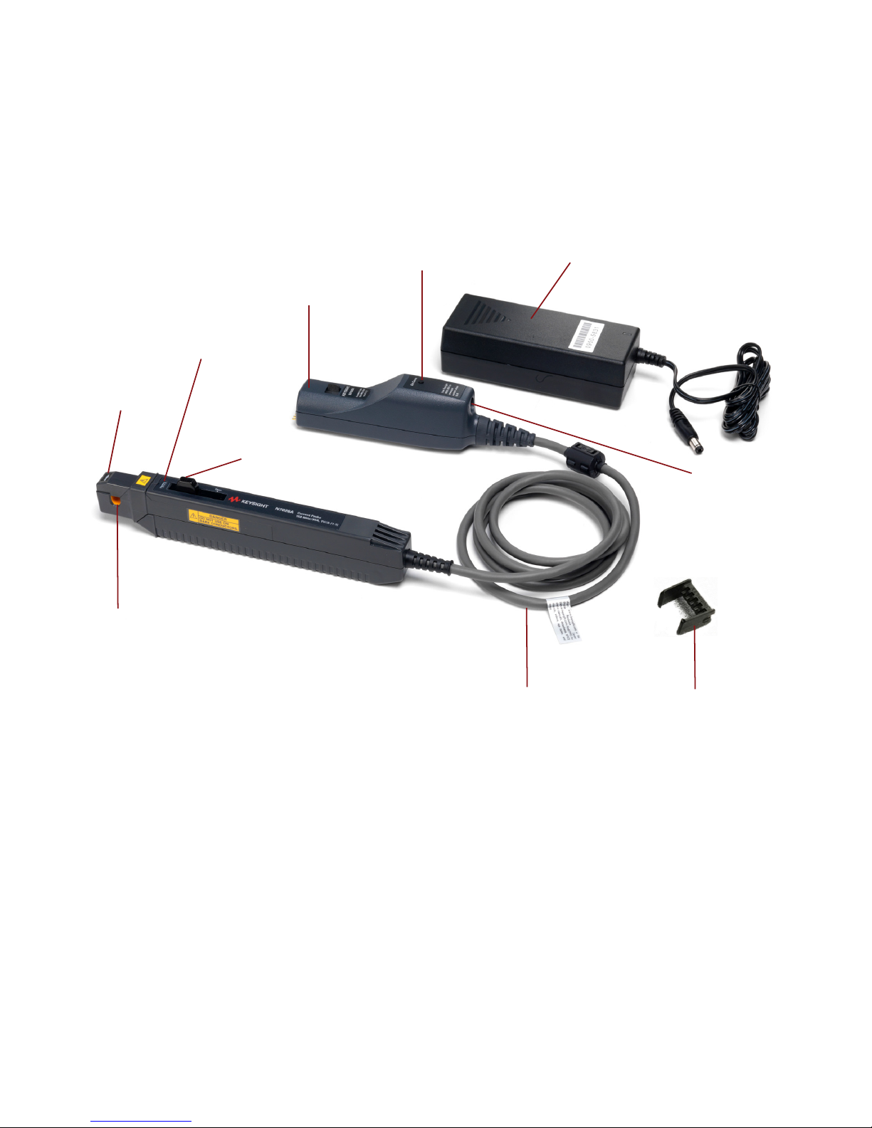
N7026A Kit Components
Sensor Head
Current Direction
Indication
Opening Lever
UNLOCK Indication
Sensor Cable
Output Connector
(with AutoProbe Interface)
Bushing
De-Gauss Button
External Power Supply Adapter
External Power Adapter
Socket
N7026A Probe
N7026A 150 MHz AC/DC High Sensitivity Current Probes User’s Guide 7
Figure 1 N7026A Kit Components
Page 8

N7026A Probe
CAUTION
Component Description
Sensor Head The sensor head clamps the conductor being measured, detects the current, and carries
out the current measurement. It is a precision assembly including a molded component, a
ferrite core, and a Hall effect element.
The sensor head may be damaged if subjected to sudden changes in
ambient temperature, or mechanical strain or shock. Care should be
exercised when handling the sensor head.
Current Direction Indication Indicates the direction of the current flow through the conductor under test.
UNLOCK Indication When you pull the probe’s opening lever to open the sensor head, the UNLOCK indication
is displayed on the sensor head. It means that the sensor head is currently in the unlocked
/ open state.
When you slide the opening lever towards the front of the sensor head and the UNLOCK
indication disappears, it means that the sensor head is currently in the locked / closed
state.
Opening Lever Operating lever for opening the sensor head. Always use this lever to open the sensor
head to avoid damaging the open-close mechanism of the sensor head.
Output Connector The pod with the AutoProbe interface to connect the probe to one of the channels of a
compatible oscilloscope.
De-Gauss Button The button to demagnetize the core if it has been magnetized by switching the power on
and off, or by an excessive input. Always carry out demagnetization before making
measurements. The probe should be connected to the oscilloscope for the demagnetizing
process. This process takes about one second. During demagnetizing, a demagnetizing
waveform is output.
Refer to ““Performing Demagnetization and Zero Offset" on page 26" to know more.
External Power Supply Adapter The power supply adapter (part number 0950-5831) is included with the probe to power
the probe using an external DC supply.
Refer to the topic “Powering the Probe" on page 17 to know more.
8 N7026A 150 MHz AC/DC High Sensitivity Current Probes User’s Guide
Page 9
N7026A Probe
CAUTION
Component Description
External Power Adapter Socket Jack DC socket to connect the probe to the power supply adapter shipped with the probe.
You use this option to power the probe using an external DC supply which allows the
probe to measure ± 30A
Refer to the topic “Powering the Probe" on page 17 to know when to use the external
power supply for the probe.
Bushing Recommended for use in the probe’s sensor aperture to minimize the measurement
variation caused by the position variation of the conductor under test within the sensor
aperture.
Refer to the topic “Installing and Removing Bushing" on page 24 to know more.
Sensor Cable The cable that connects the probe’s sensor to the output pod.
To avoid damaging the cable, do not tightly bend or pull the cable.
RMS
.
N7026A 150 MHz AC/DC High Sensitivity Current Probes User’s Guide 9
Page 10
N7026A Probe
Characteristics and Specifications
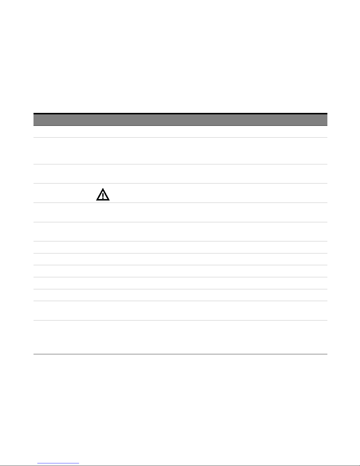
Table 1 Measurement Characteristics
Item Characteristic
a
Probe Bandwidth (-3 dB) DC to 150 MHz
Amplitude Accuracy
b
±1% of reading ±1mV (DC or 45 Hz to 66 Hz, with calibrated gain factor)
± 1% of reading. ±5 mA to 30 A
(including calibration scale factor of oscilloscope
rms
measured at DC or 45 to 66 Hz.)
Rise Time (calculated, 10% to
90%)
Maximum Continuous
Current
Maximum Non-continuous Peak
~
Current (for Pulse Widths
10µs)
2.67 ns
(Rise time is calculated as: Tr = 0.4/Bandwidth)
, 30 A
30A
DC
5ADC, 5 A
40 A
peak
15 A
peak
(when powering the probe using the external power adapter)
rms
(when the external power supply is NOT used)
rms
(when powering the probe using the external power adapter)
(when the external power supply is NOT used)
Probe Sensitivity 1 V/A and 0.2 V/A
(automatically configured and switched by the oscilloscope)
Noise ~ 250 µA
(for 20 MHz bandwidth measuring instrument)
rms
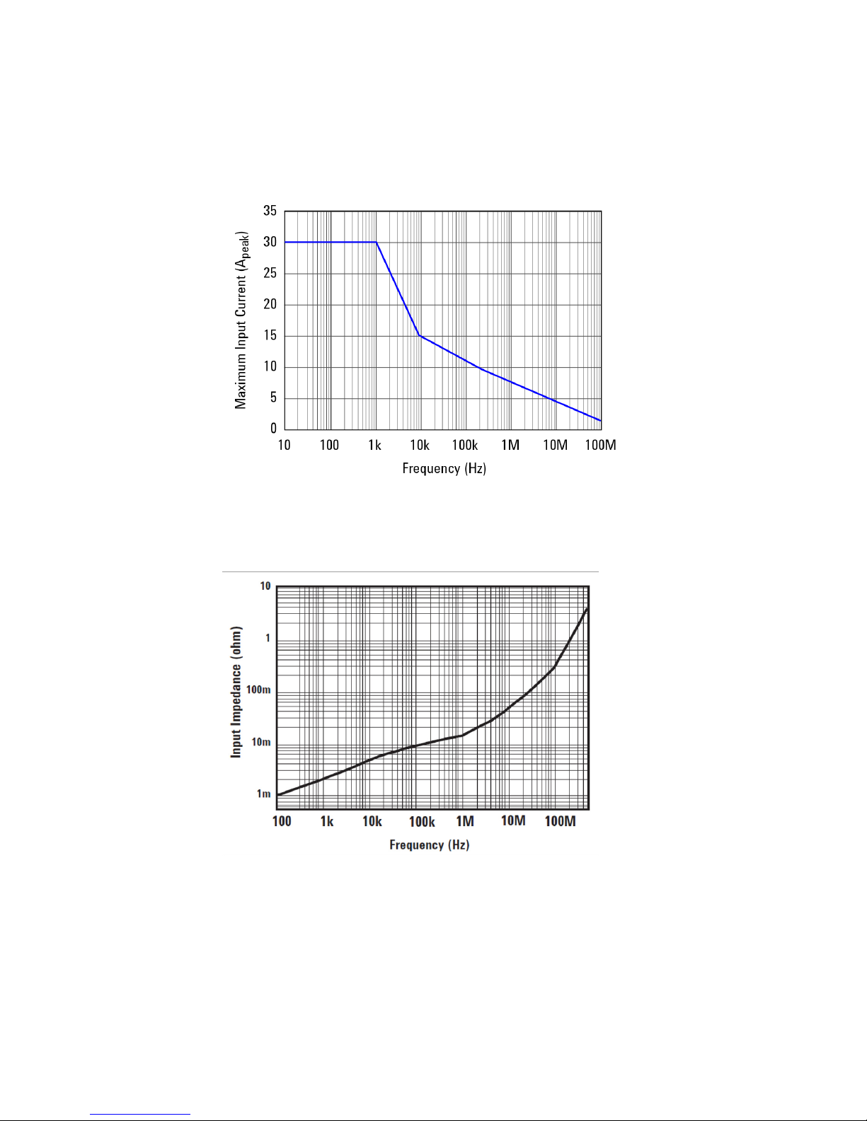
Insertion Impedance See Figure 16 on page 36.
Temperature Coefficient ±2% or less (within a range of 0°C to 40°C or 32 to 104 °F)
Effect of External Magnetic Fields Equivalent to a maximum of 20 mA (in a DC to 60 Hz, 400 A/m magnetic field)
Maximum Rated Power 3 VA (with rated current)
Minimum oscilloscope vertical
1 mA/div
scale
Maximum Number of Probes
Supported
2 (for use with 3000XT series oscilloscopes without external power adapter)
4 (for use with 3000XT series oscilloscopes with external power adapter)
2 (for use with 9000 series oscilloscopes)
4 (for use with 4000X, 6000X, S-Series oscilloscopes)
aRequires 1MΩ termination. Valid for 23°C ±3°C (73°F ±5°F), at least 30 minutes after power on.
b This is a specification and is guaranteed at 23°C ±3°C (73°F ±5°F.
10 N7026A 150 MHz AC/DC High Sensitivity Current Probes User’s Guide
Page 11
N7026A Probe
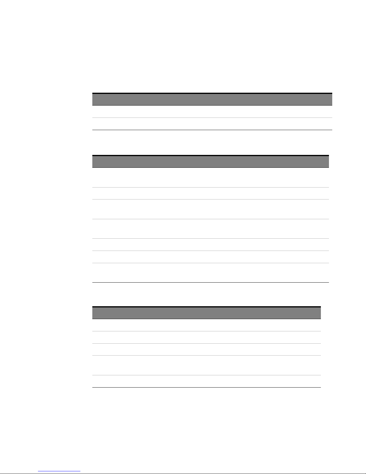
Table 2 Power Supply Characteristics
Item Characteristics
DC Supply Voltage Requirements ±12Vdc ±1V
Probe Power Consumption Increases with measured current. 3 VA when measuring 15A
Table 3 Mechanical Characteristics
Item Characteristics
Maximum Diameter of Measurable
Conductors
Sensor Cable Length 1.5 m (59.0 in.)
Dimensions (Sensor) 175 mm x 18 mm x 40 mm
Dimensions (Output Pod) 28 mm x 39 mm x 145 mm
Probe Interface AutoProbe Interface (1 MΩ terminated)
Weight 275 g (9.7 oz.)
Accessories Supplied Storage case, calibration certificate, power supply adapter,
5 mm (0.2 in.)
6.89 in. x 0.71 in. x 1.6 in.
1.1 in. x 1.5 in. x 5.7 in.
bushing kit
Table 4 Environmental Characteristics
Item Characteristics
Use Indoor
Operating Temperature Range 0°C to 40°C (32°F to 104°F)
Storage Temperature Range –10°C to 50°C (14°F to 122°F)
Maximum Relative Humidity
(Operating or Storage)
Maximum Altitude 2000m
N7026A 150 MHz AC/DC High Sensitivity Current Probes User’s Guide 11
80% (no condensation)
Page 12
N7026A Probe
NOTE
Compatibility with Oscilloscopes
You can use these probes with any Keysight Infiniium or InfiniiVision
oscilloscope that has the following features.
- Minimum input impedance of 1MΩ
- AutoProbe connector
Infiniium Oscilloscopes InfiniiVision Oscilloscopes
S-Series 3000T X Series
9000 Series 3000A X-Series
9000H Series 4000 X Series
6000 X-Series
Infiniium Software Version InfiniiVision Software Version
Compatible with Infiniium
software version 6.10 or higher
Compatible with InfiniiVision
software version 7.20 or higher
12 N7026A 150 MHz AC/DC High Sensitivity Current Probes User’s Guide
Page 13

Inspecting the Probe
- Inspect the shipping container for damage.
- Keep the damaged shipping container or cushioning material until the contents of the
shipment have been checked for completeness and the probe has been checked
mechanically and electrically.
- Check the accessories. If the contents are incomplete or damaged, notify your Keysight
Technologies Sales Office.
- Inspect the probe. If there is mechanical damage or defect, or if the probe does not
operate properly or pass calibration tests, notify your Keysight Technologies Sales
Office.
- If the shipping container is damaged, or the cushioning materials show signs of stress,
notify the carrier as well as your Keysight Technologies Sales Office. Keep the shipping
materials for the carrier’s inspection. The Keysight Technologies office will arrange for
repair or replacement at Keysight Technologies’ option without waiting for claim
settlement.
N7026A Probe
N7026A 150 MHz AC/DC High Sensitivity Current Probes User’s Guide 13
Page 14

N7026A Probe
WARNING
Cleaning the Probe
You should inspect and clean the probe regularly to prevent any surface contamination. If
the probe requires cleaning:
1 Disconnect the probe from the oscilloscope, external power supply, and any circuit under
test.
2 Gently clean the probe with a soft cloth dampened with a mild soap and water solution.
3 Wipe with clean water to remove the detergent and then dry thoroughly with a clean cloth.
Do not try to clean the probe using cleaners containing organic solvents such as benzine, alcohol,
acetone, ether, ketones, thinners, or gasoline. These may cause discoloration or damage. Make sure
the probe is completely dry before reconnecting it for use.
Cleaning the Sensor Head
The presence of foreign substances such as dust on the mating surfaces of the probe’s
sensor head can cause acoustic resonance and degraded measurements, Therefore, keep
these mating surfaces clean by gently wiping with a soft cloth.
14 N7026A 150 MHz AC/DC High Sensitivity Current Probes User’s Guide
Page 15
Safety Information
WARNING
WARNING
DANGER
DANGER
WARNING
WARNING
This manual provides information and warnings essential for operating this equipment in a
safe manner and for maintaining it in safe operating condition. Before using this equipment,
be sure to carefully read the following safety notes.
This equipment is designed according to IEC 61010-1 Safety Standards, and has been tested for
safety prior to shipment. Incorrect measurement procedures could result in injury or death, as well as
damage to the equipment. Please read this manual carefully and be sure that you understand its
contents before using the equipment. The manufacturer disclaims all responsibility for any accident or
injury except that resulting due to defect in its product.
Do not install substitute parts or perform any unauthorized modification to the instrument. Only
Keysight service centers should perform repair/maintenance on the equipment.
N7026A Probe
To avoid short circuits and accidents that could result in injury or death, use the probe only
with insulated power lines carrying 300V or less.
Never use this sensor on uninsulated conductors. The core and shield case are not
insulated. Before clamping the insulated conductor being measured, make sure that the
insulation on the conductor is undamaged. Any damage to the insulation can cause an
electric shock.
Ensure that the input does not exceed the maximum rated current to avoid device damage,
short circuiting, and electric shock.
Do not subject the unit to vibrations or shocks during transport or handling. Be especially careful to
avoid dropping the unit.
N7026A 150 MHz AC/DC High Sensitivity Current Probes User’s Guide 15
Page 16

N7026A Probe
WARNING
WARNING
WARNING
WARNING
WARNING
Do not store the unit where it will be exposed to direct sunlight, high temperature, high humidity, or
condensation. If exposed to such conditions, the unit may be damaged, the insulation may deteriorate,
and the unit may no longer satisfy its specifications.
This unit is not constructed to be dustproof, so do not use it in a very dusty environment.
The sensor head is a precision assembly including a molded component, a ferrite core, and a Hall
effect element. It may be damaged if subjected to sudden changes in ambient temperature, or
mechanical strain or shock, and therefore great care should be exercised in handling it.
To avoid scratching the surfaces of the Hall effect elements, keep the core section of the sensor
closed, except when clamping it around the insulated conductor to be measured.
Before turning on the instrument, you must connect the protective earth terminal of the instrument to
the protective conductor of the (mains) power cord. The mains plug shall only be inserted in a socket
outlet provided with a protective earth contact. You must not negate the protective action by using an
extension cord (power cable) without a protective conductor (grounding).
16 N7026A 150 MHz AC/DC High Sensitivity Current Probes User’s Guide
Page 17
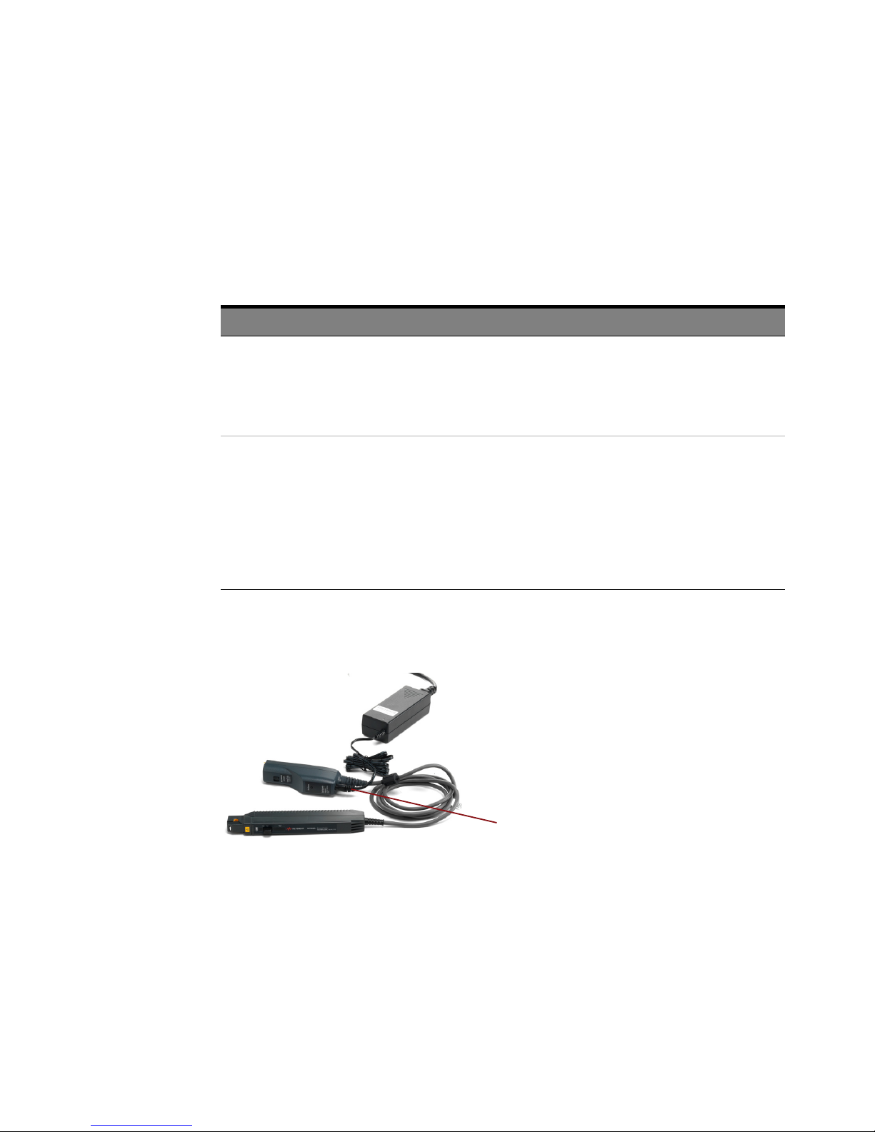
Powering the Probe
External power supply
plugged into N7026A
You can power the N7026A probe in the following two ways:
Table 5 Powering the N7026A Probe
Powering Option When to Use This Powering Option
N7026A Probe
Using the oscilloscope’s AutoProbe
interface
Using the external DC power supply The probe has an external power supply socket and it ships with
The probe’s output connector has the AutoProbe 1 interface that
allows the probe to automatically receive ± 12V power supplies
from the oscilloscope on connection.
With this powering option, the maximum peak current that you
can measure is ± 15A.
a power supply adapter to allow you to use an external power
supply to power the probe.
An external power supply is needed if you want to use the probe
to measure currents larger than the maximum peak current you
can measure when powering the probe from the oscilloscope.
With an external power supply, you can measure the maximum
current of ± 30A
Using the External DC Power Supply
RMS
.
When the external power supply is plugged into the probe, the power supply received from
the oscilloscope is automatically disconnected and the external power supply is used. If the
AC adapter output voltage is incorrect, the probe will automatically switch to oscilloscope
power.
N7026A 150 MHz AC/DC High Sensitivity Current Probes User’s Guide 17
Page 18

N7026A Probe
CAUTION
When the external power supply is connected or removed, it causes a degauss operation
that can influence the DUT. It is therefore recommended that you:
- disconnect the probe from the circuit when inserting or removing the DC jack from the
probe’s external power supply socket.
- plug the power cord into the outlet and the external power supply adapter prior to
inserting the jack into the probe’s power supply socket.
18 N7026A 150 MHz AC/DC High Sensitivity Current Probes User’s Guide
Page 19
Setting up the Probe
WARNING
NOTE
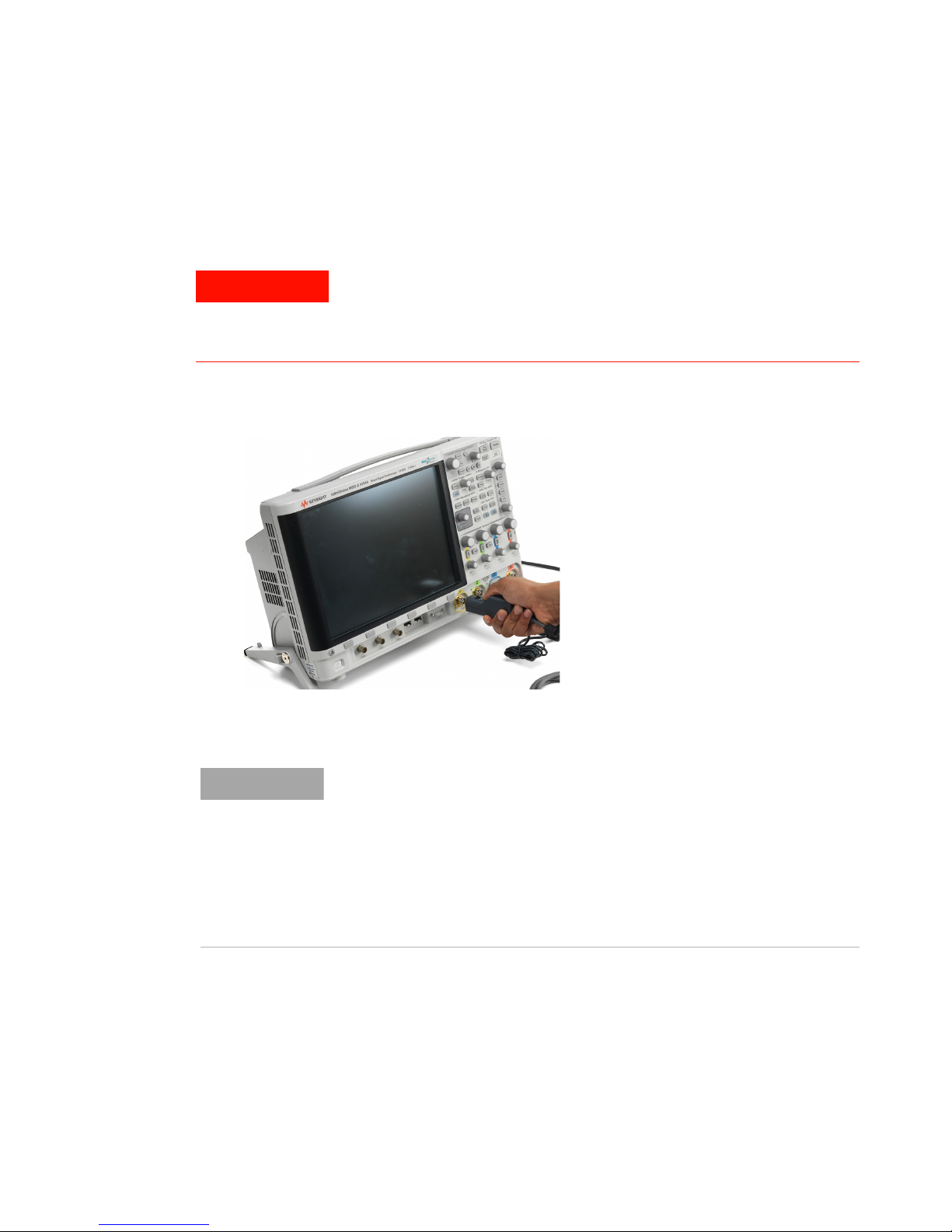
1 Power on the oscilloscope.
2 Connect the probe to one of the oscilloscope’s channels.
N7026A Probe
Ensure all safety warnings and precautions are followed. Before using the probe,
read the warnings and precautions in “Safety Information" on page 15.
Also, take precautions mentioned in “Protecting the Probe Against Damage
Resulting from Excessive Input" on page 28.
Figure 2 Connecting the Probe to the Oscilloscope
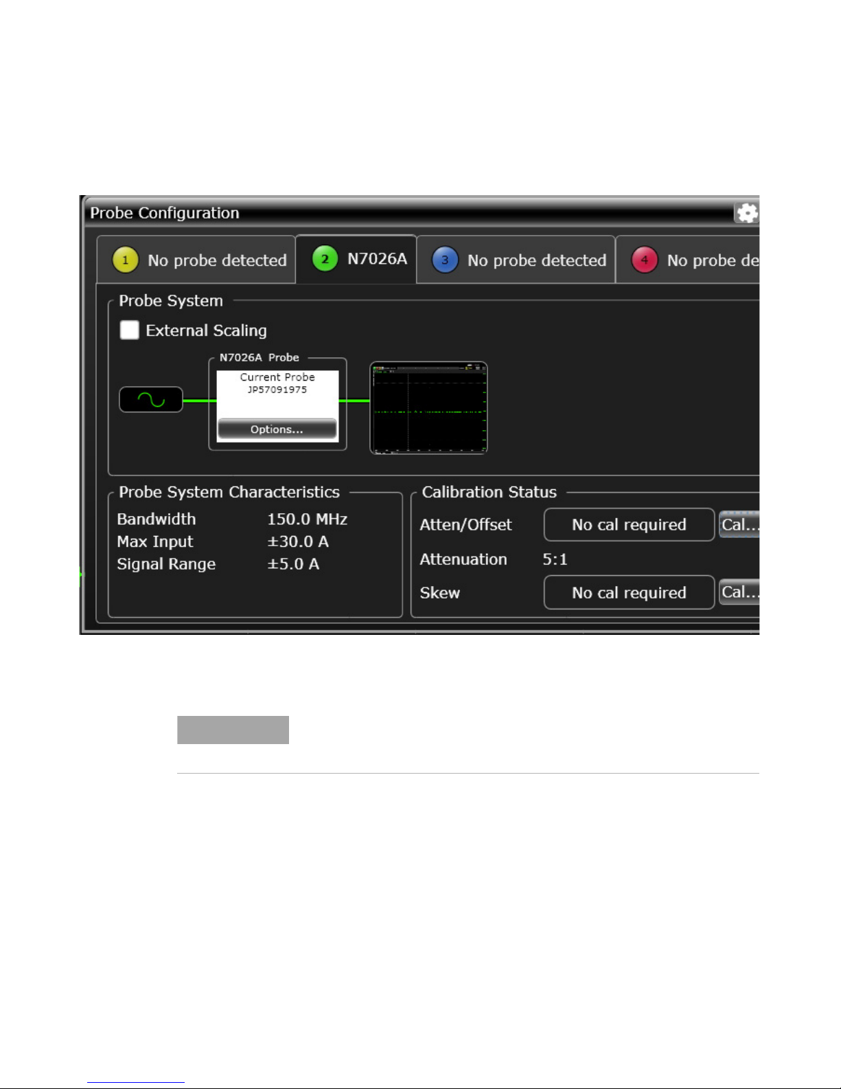
( When the probe is connected to an oscilloscope channel, the AutoProbe interface
recognizes the probe as an N7026A and automatically configures several settings on
the channel to which the probe is connected.
For instance, the 1 MΩ input impedance will be automatically selected on the
oscilloscope, as the probe is plugged into the AutoProbe interface. (With an input
impedance of 50Ω, accurate measurements are not possible.)
Also, the probe output sensitivity 0.2 V/A or 1V/A will be automatically selected, as the
probe is plugged into the AutoProbe interface.
N7026A 150 MHz AC/DC High Sensitivity Current Probes User’s Guide 19
Page 20
N7026A Probe
NOTE
Figure 3 N7026A probe auto-recognized on an Infiniium oscilloscope on connection
Immediately after powering on, this probe may be subject to an appreciable offset drift
due to the effect of self-heating. To counteract this, allow the probe to warm up for
about 30 minutes before carrying out measurements.
3 If you want to measure larger currents, connect the probe to an external power supply. Plug
the external power adapter shipped with the probe into the external power supply socket on
the probe’s output connector.
20 N7026A 150 MHz AC/DC High Sensitivity Current Probes User’s Guide
Page 21
N7026A Probe
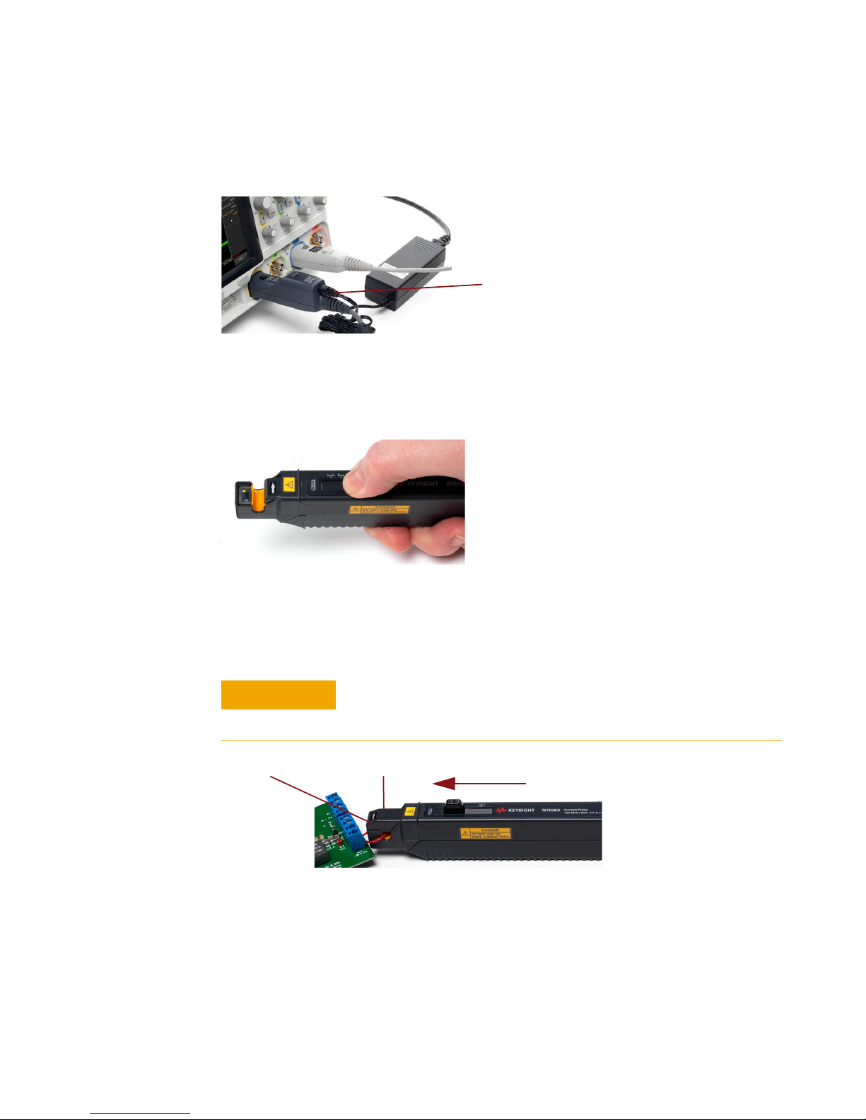
External power supply
plugged into N7026A
CAUTION
Slide the lever forward until
the UNLOCK indication disappears
Do Not Press Here!
Upper Core
4 Perform the steps described in “Performing Demagnetization and Zero Offset" on page 26.
Always carry out demagnetization before making measurements.
5 Pull the probe’s opening lever to open the sensor head. The UNLOCK indication is displayed
on the sensor head. Keep sliding the lever backwards into the Open position.
6 With the probe’s sensor head around the insulated conductor to be measured, slide the
opening lever of the probe towards the front of the sensor head into the Lock position. While
doing so, ensure that the UNLOCK indication disappears which indicates that the sensor
head is properly closed. If the sensor head is not closed properly, accurate measurements
will not be possible.
Always use the opening lever when opening/closing the probe’s
sensor head. If the upper core is forced to open when the sensor head
is locked, the open-close mechanism can be damaged.
Figure 4 Use the Opening Lever
N7026A 150 MHz AC/DC High Sensitivity Current Probes User’s Guide 21
Page 22

N7026A Probe
NOTE
Under certain circumstances, oscillation may occur if the probe is connected to the
AutoProbe interface while the oscilloscope is on. This does not indicate a
malfunction. Oscillation can be stopped and operation can be restored to normal by
opening and closing the sensor head.
22 N7026A 150 MHz AC/DC High Sensitivity Current Probes User’s Guide
Page 23
Obtaining the Best Measurement Accuracy
NOTE
NOTE
To obtain the best measurement accuracy, ensure that:
- The current direction indicator on the sensor aligns with the actual current direction in
the insulated conductor.
- The sensor opening lever is in the Locked position and the sensor head is properly
closed.
- The conductor under test is positioned in such a way that it is in the center of the sensor
head aperture.
- Bushing is installed on the probe’s sensor aperture if the diameter of the conductor
under test including its insulation is less than 1.65mm. Refer to the topic “Installing and
Removing Bushing" on page 24 to know more.
- At high frequencies, common mode noise may affect measurements taken on the high
voltage side of circuits. If this occurs, reduce the frequency range of the measuring
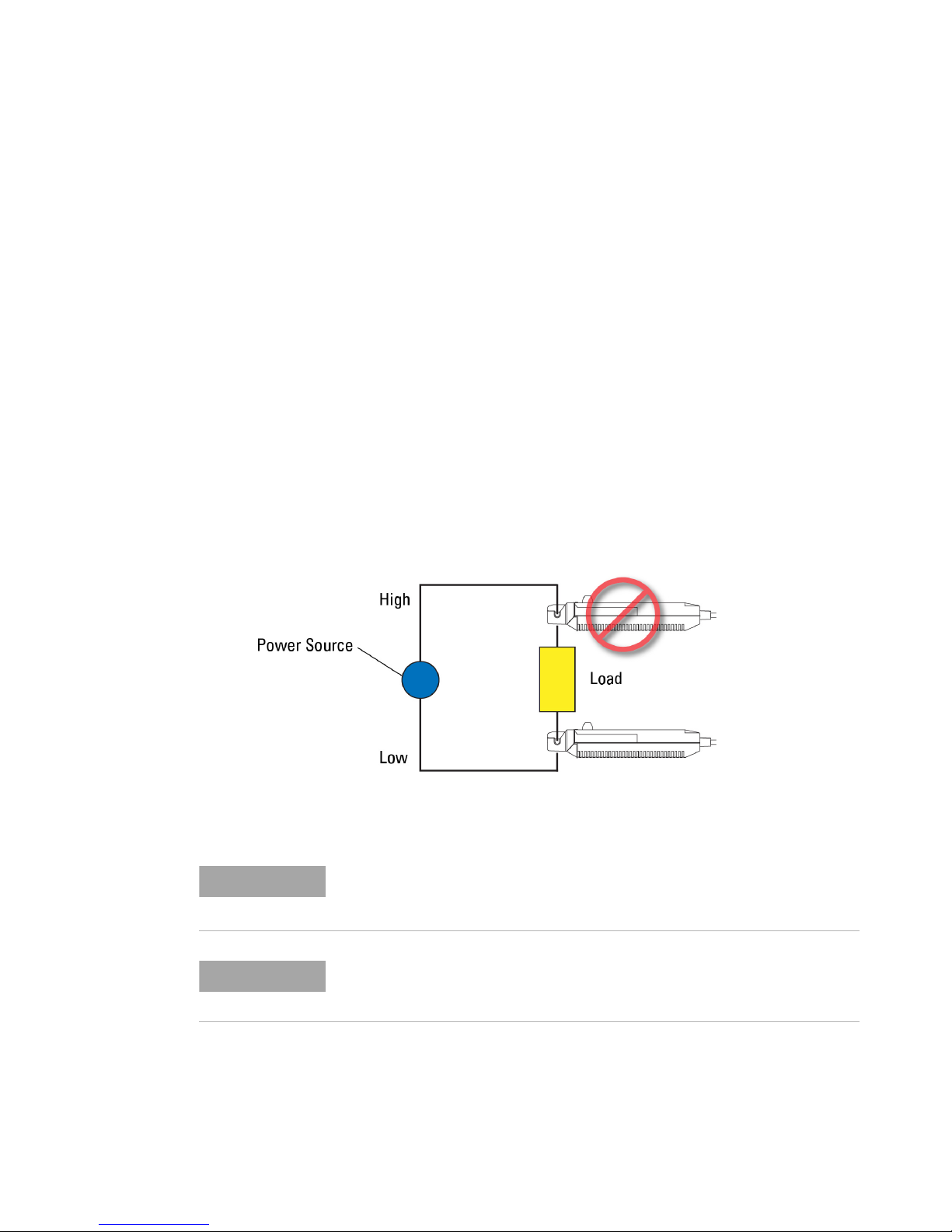
instrument or clamp onto the low-voltage side of the circuit as shown in Figure 5, as
appropriate.
N7026A Probe
Figure 5 Clamp Onto the Low-Voltage Side of Circuit
N7026A 150 MHz AC/DC High Sensitivity Current Probes User’s Guide 23
Accurate measurement may be impossible in locations subject to strong external
magnetic fields, such as transformers and high-current conductors, or in locations
subject to strong external electric fields, such as radio transmission equipment.
When performing continuous measurements, it is necessary to be aware that the zero
offset voltage will drift if the ambient temperature changes.
Page 24
N7026A Probe
NOTE
CAUTION
Bushing
Installing and Removing Bushing
At some frequencies, some sound may be produced by resonance. This has no effect
on measurements.
Variation in the position of the conductor under test within the probe’s sensor aperture can
cause variation in the measurement results. To achieve measurement accuracy, the position
of the conductor under test within the sensor aperture should not vary and should lie in the
center of the aperture. If the diameter of your conductor under test (including the insulation
around it) is less than 1.65mm, it is recommended that you use bushing on the probe’s
sensor aperture. This minimizes measurement variations that may be caused due to the
variation in the position of the conductor under test.
Bushing (Keysight part number N7026-41201) is shipped with the N7026A probe.
Avoid touching the sensor's core surfaces while installing or removing the bushing.
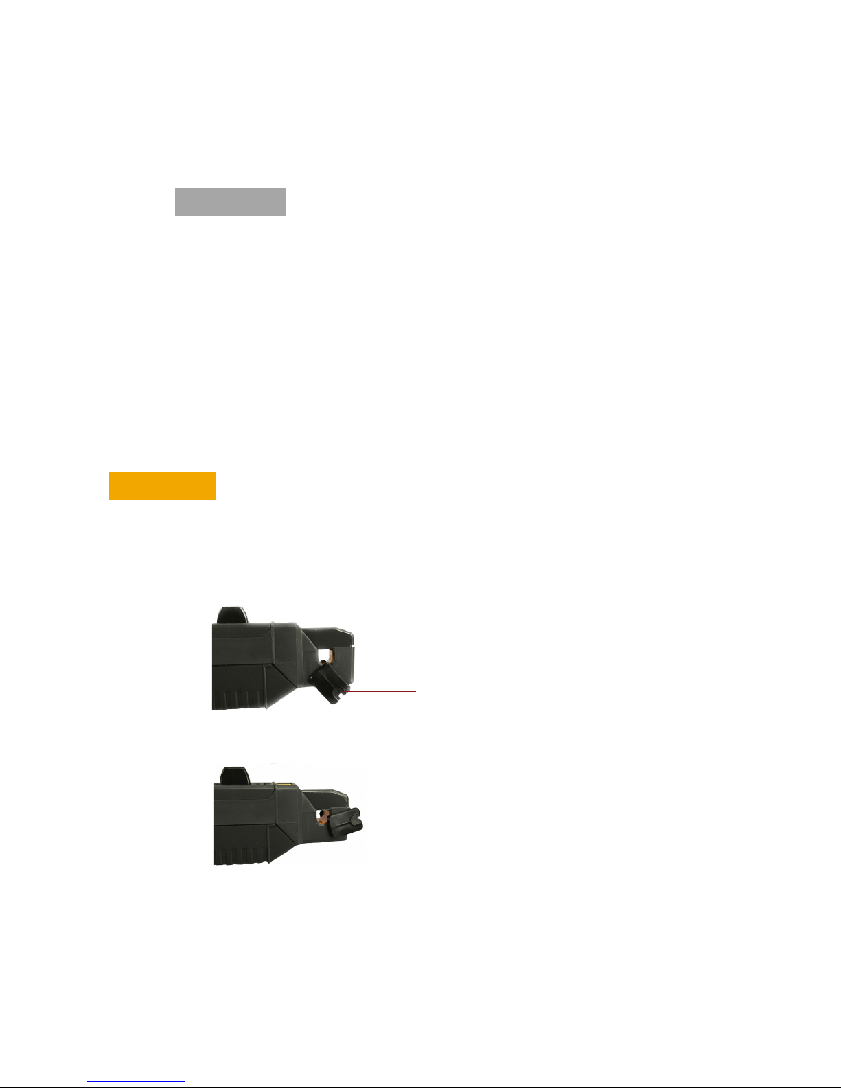
To install bushing on the sensor aperture
1 Push the open end of the bushing over the bottom of the probe’s sensor head.
2 Turn around the bushing to bring it to the front of the sensor head.
3 Slide the probe’s opening lever to open its sensor head.
4 Continue turning around the bushing and then gently push it down so as to place it
correctly inside the sensor aperture.
24 N7026A 150 MHz AC/DC High Sensitivity Current Probes User’s Guide
Page 25
N7026A Probe
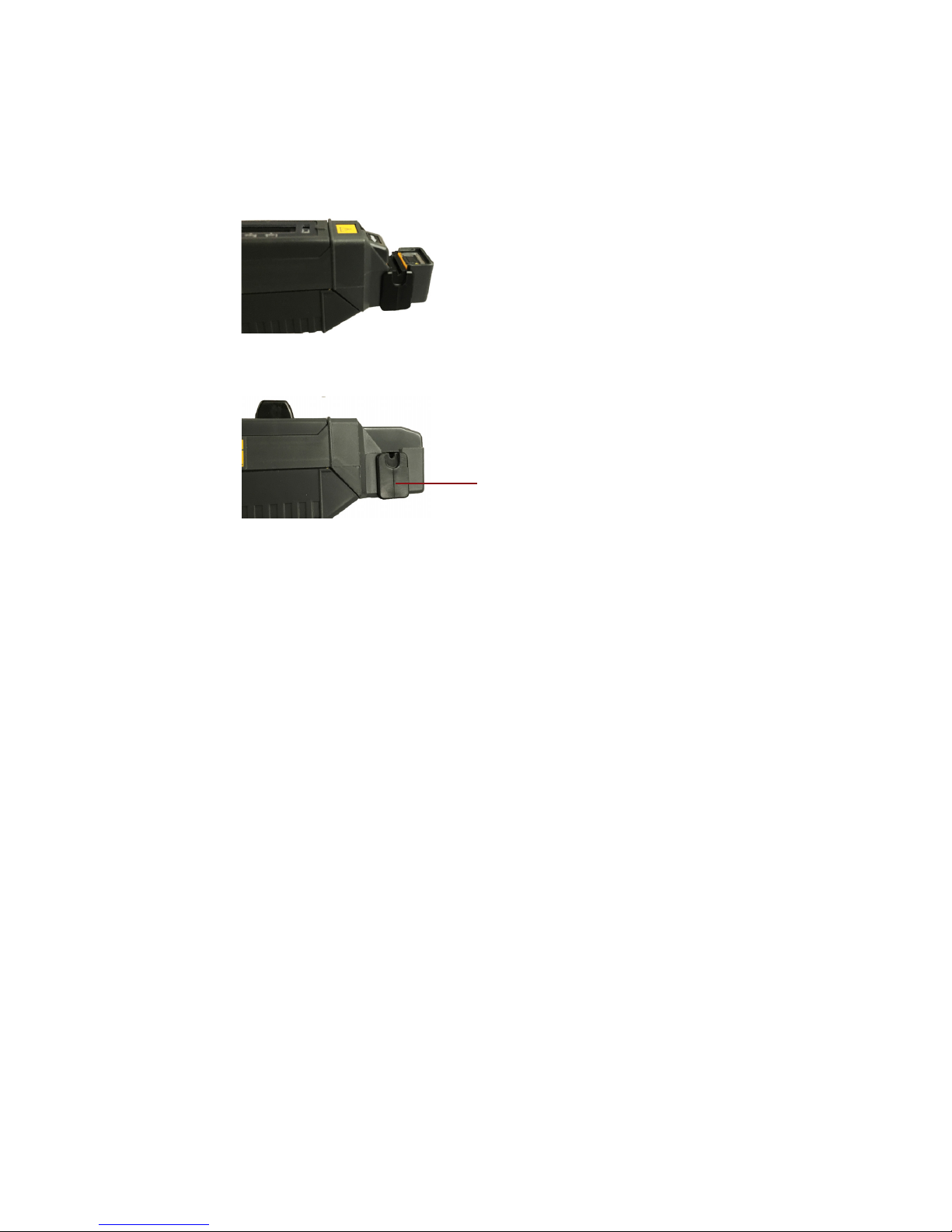
Bushing installed
A correctly installed bushing is displayed in the following picture.
To remove bushing from the sensor aperture
1 Slide the probe’s opening lever to open its sensor head.
2 Gently pull the bushing straight up and away from its installed position on the sensor
aperture.
N7026A 150 MHz AC/DC High Sensitivity Current Probes User’s Guide 25
Page 26
N7026A Probe
NOTE
WARNING
Performing Demagnetization and Zero Offset
Before you Start
Allow both the oscilloscope and probe to warm up for at least 30 minutes
before making these adjustments.
DO NOT press the De-Gauss button to perform demagnetization while the
conductor being measured is clamped. Doing so can damage the circuitry or
cause an accident.
1 Set the channel offset to 0V for the oscilloscope channel to which the probe is connected.
2 Ensure that the probe sensor is NOT clamped around a conductor.
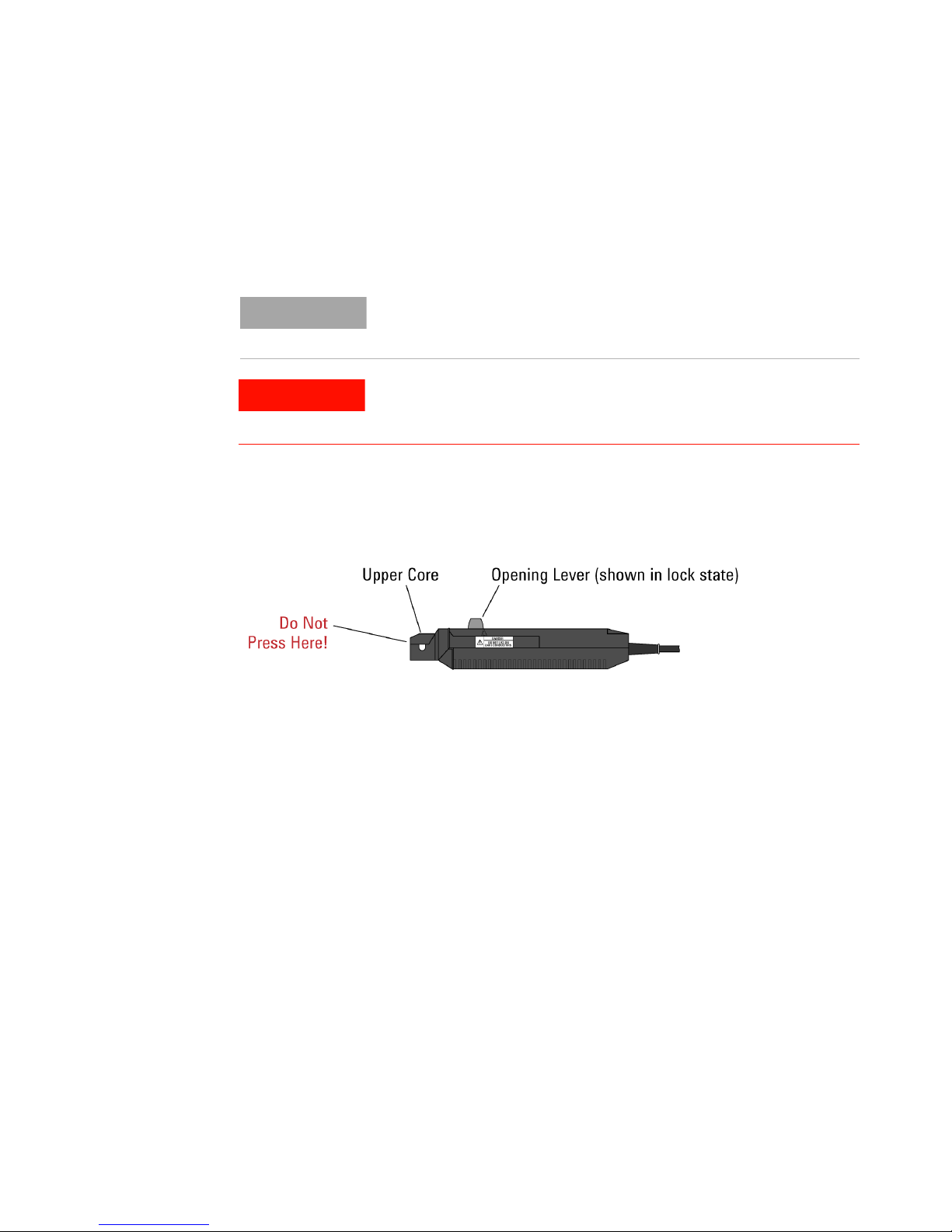
3 Slide the probe’s Opening Lever forward into the Lock position as shown in the figure below.
The UNLOCK indication on the sensor head disappears when the probe is locked properly.
Figure 6 Lock the sensor head
To perform demagnetization
1 Press the probe’s De-Gauss button shown in Figure 1 on page 7. A demagnetization
waveform will be displayed for a short time on the channel to which the probe is connected.
Wait until this waveform is no longer displayed.
To perform zero offset operation
You can use one of the following methods for the zero offset (Auto Zero routine):
- Press and hold the De-Gauss button on the probe for approximately three seconds. This
initiates a degauss operation and then triggers the oscilloscope to perform a zero offset
operation.
- Or use the Probe menu in the Infiniium / InfiniiVision software GUI to automatically
initiate the demagnetization followed by the zero offset operation.
26 N7026A 150 MHz AC/DC High Sensitivity Current Probes User’s Guide
Page 27

N7026A Probe
On Infiniium oscilloscopes:
a Click Setup > Probe Calibration.
b In the displayed dialog box, click the AutoZero button to automatically start the
demagnetization followed by the zero offset routine. Follow the on-screen
instructions.
On InfiniiVision oscilloscopes:
a Press the scope’s channel button (1, 2, 3, or 4) to which the probe is
connected.
b Click the Probe softkey (under the display) and then press the key to automatically
start the demagnetization followed by the zero offset routine. Follow the on-screen
instructions.
N7026A 150 MHz AC/DC High Sensitivity Current Probes User’s Guide 27
Page 28

N7026A Probe
WARNING
WARNING
WARNING
Protecting the Probe Against Damage Resulting from Excessive
Input
The steps and guidelines provided in this topic must be followed to ensure that your
probe is protected against any damage caused due to the input current that exceeds
the maximum continuous input range for the probe.
The maximum continuous input range is based on heat that is internally generated during
measurement. This range varies according to the frequency of the current being measured.
See Figure 15 on page 36 to know about the maximum continuous input range for the
N7026A probe. It is recommended not to exceed this range.
Built-in Safety Function
In the following situations, the generated heat activates a built-in safety function in
the probe that blocks normal output to prevent probe damage resulting from heating.
- If the input current exceeds the maximum continuous input range.
- Continuous input for an extended period of time (even if the input current does not
exceed the rated continuous maximum).
- At high ambient temperatures, the built-in safety function may activate even at
current input levels below the rated continuous maximum.
In such situations, when the built-in safety function is activated:
1 Remove the input immediately (unclamp the sensor from the conductor being measured or
reduce the input current to zero).
2 Wait until the sensor on the probe had the sufficient time to cool before resuming
operation.
When the input current is dropped to within the allowed current range and the probe is
allowed to cool down, the normal operation of the probe is restored.
If there is continuous input of current exceeding the rated maximum or repeated
activation of the built-in safety function, it may result in damage to the probe.
28 N7026A 150 MHz AC/DC High Sensitivity Current Probes User’s Guide
Page 29
N7026A Probe
WARNING
Do NOT measure current such that the total probe current consumption exceeds the
allowable AutoProbe interface current consumption. The excess current
consumption causes a temporary shutdown of the oscilloscope’s power supply for
safety. Quit the measurement and cycle the power of the oscilloscope, if the
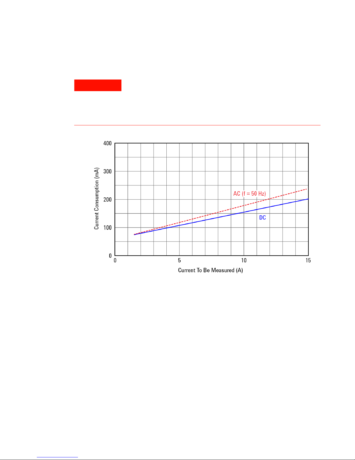
shutdown occurs. The typical probe current consumption from the AutoProbe
interface is shown in Figure 7.
Figure 7 Typical Probe Consumption
N7026A 150 MHz AC/DC High Sensitivity Current Probes User’s Guide 29
Page 30
N7026A Probe
Performance Verification for N7026A
Use the following procedure to test the warranted Accuracy specifications for the N7026A
probe (as listed on page 10). The recommended test interval to warrant performance of this
probe is once a year. However, you can also test the probe’s performance as and when
required using the recommended test equipment and by following the procedure
documented in this chapter.
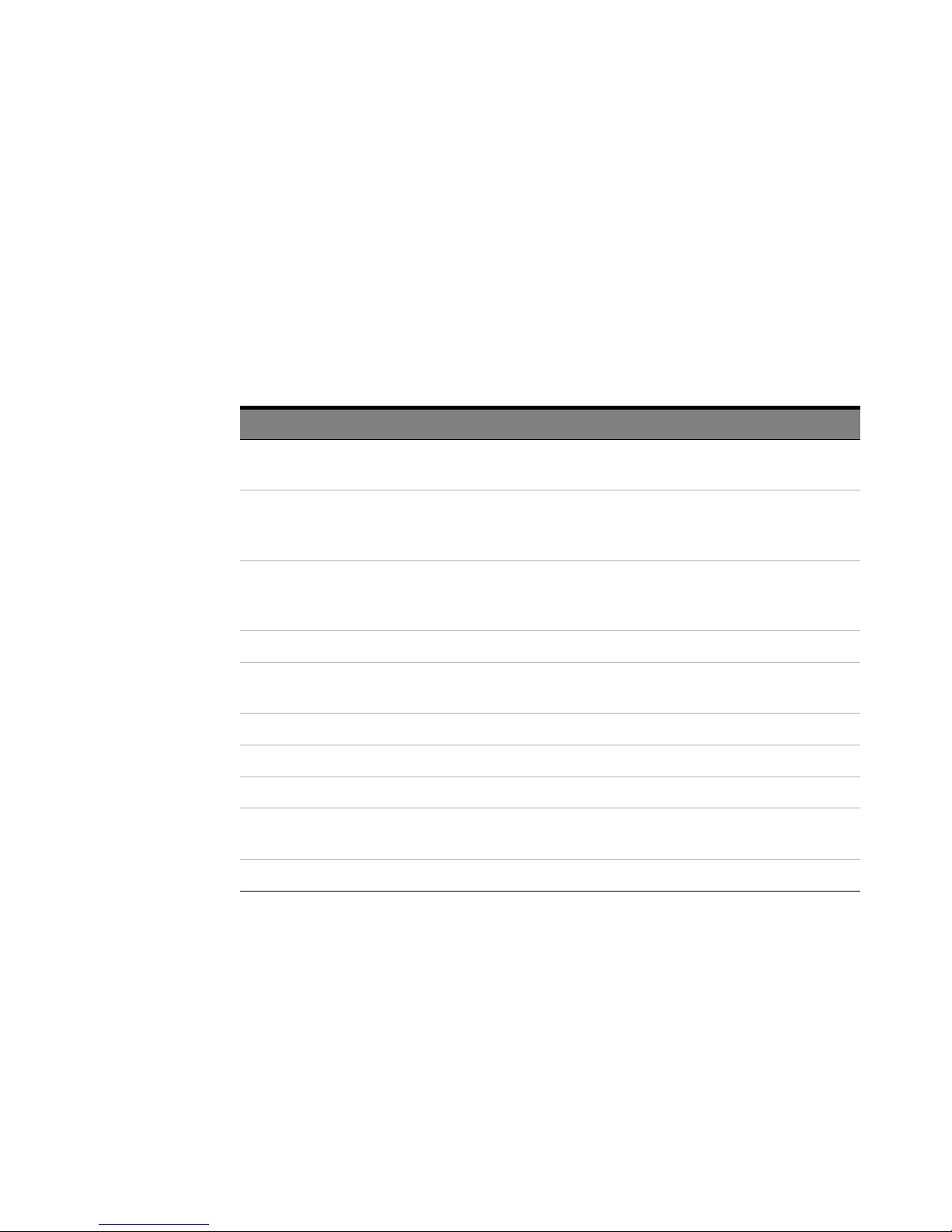
Table 6 Required Test Equipment
Description Minimum Requirements Recommended Test Equipment
Oscilloscope Bandwidth ≥ 250 MHz
Amplitude accuracy: ≤ 0.4%
Two Digital Multimeters - Keysight U1251B Handheld
AC Current Generator AC 10 A
wave
Amplitude accuracy: ≤0.3%
Probe Adapter - Keysight N1022B Probe Adapter
Power Supply - Keysight 1143A Probe Offset
Test Cables (with banana jacks) - -
BNC Cable - -
BNC (F) to Banana Adapter - -
NMD 3.5mm (M) to 3.5mm (F)
adapter
3.5mm (M) to BNC (F) adapter - -
--
, 50 or 60 Hz, sine
rms
Infiniium or InfiniiVision with
1MΩ input
Digital Multimeter or equivalent
DVM/DMM
Keysight AC6800 or Wavetek
9100
Control and Power Module
Procedure
1 Turn on the oscilloscope and then connect the N7026A probe to the oscilloscope.
2 Set A/div to 10mA/div.
3 On an Infiniium oscilloscope, choose Setup > Probe Configuration.... to access the Probe
Configuration dialog box and then record the Attenuation scale factor. On an InfiniiVision
oscilloscope, use th
30 N7026A 150 MHz AC/DC High Sensitivity Current Probes User’s Guide
e Probe softkey to record the attenuation scale factor of the probe.
Page 31
N7026A Probe
The
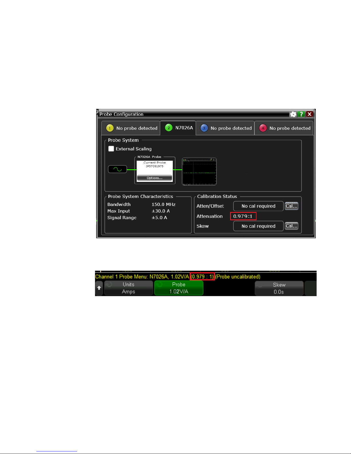
attenuation scale factor should be 1 ±10%. If the scale factor is beyond 1
±10%, then return the probe for service. Examples of correct attenuation scale
factor are shown below.
Figure 8 Attenuation scale factor on an Infiniium oscilloscope
Figure 9 Attenuation scale factor on an InfiniiVision oscilloscope
4 Remove the N7026A probe from the oscilloscope.
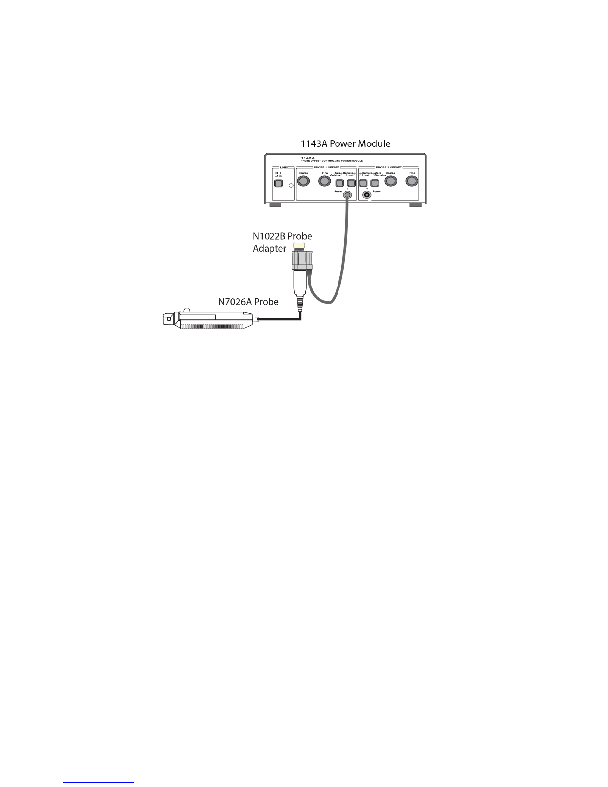
5 To provide power to the N7026A probe, connect the power cord of the N1022B probe
adapter to the Power connector on the front panel of the 1143A power module. Then
connect the N7026A probe’s output to the N1022B probe adapter’s input.
N7026A 150 MHz AC/DC High Sensitivity Current Probes User’s Guide 31
Page 32
N7026A Probe
Figure 10 Providing power to the N7026A probe
6 Turn on the equipment.
7 Wait for 20 minutes to allow the probe to warm up.
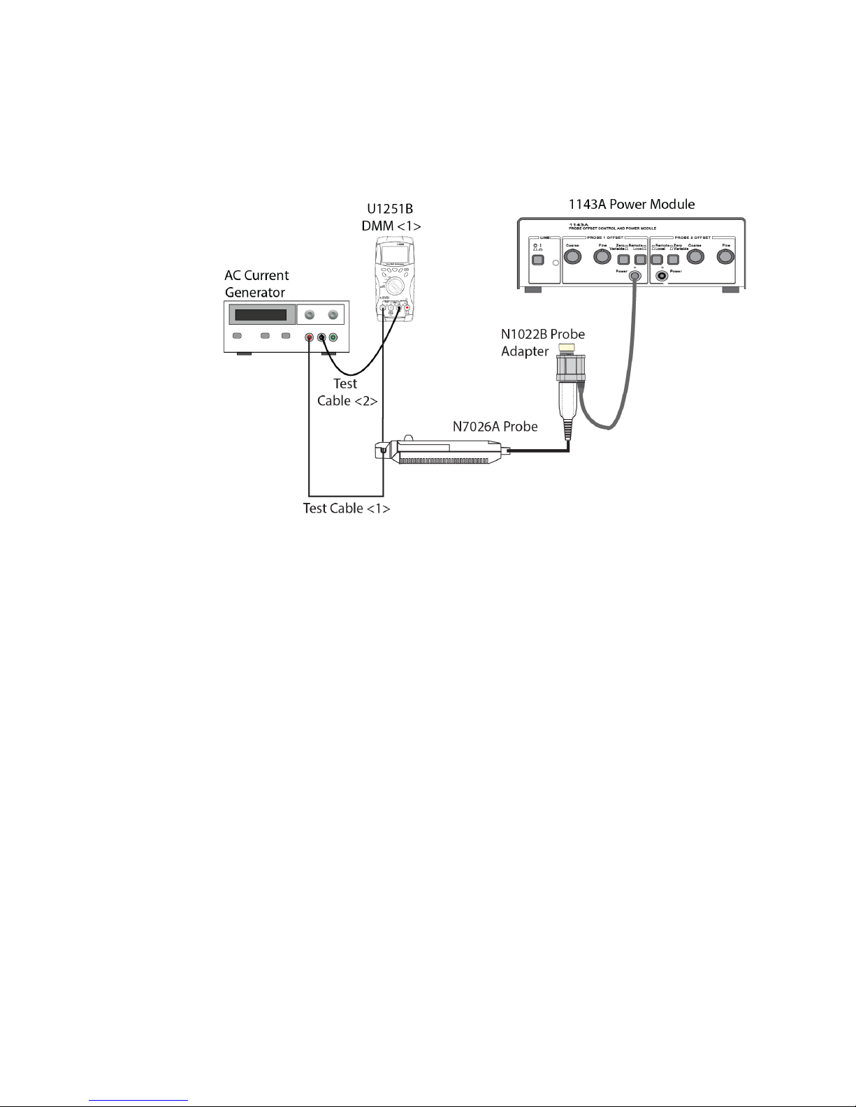
8 Connect the test setup as shown in Figure 11 as per the following substeps.
a Clamp the N7026A probe around the test cable <1> and lock the sensor head of the
probe.
b Press the De-Gauss button on the probe.
c Set the digital multimeter (DMM <1>) to A
rms
mode.
d Connect the test cable <1> to the positive terminal of the AC current generator's
OUTPUT terminal block and to the current input of the DMM <1>.
e Connect the test cable <2> to the negative terminal of the AC current generator's
OUTPUT terminal block and to negative input of the DMM <1>.
f Using the DMM <1>, set the output current of AC current generator to 1A
rms
.
32 N7026A 150 MHz AC/DC High Sensitivity Current Probes User’s Guide
Page 33
N7026A Probe
Figure 11 Setting up AC Current Generator
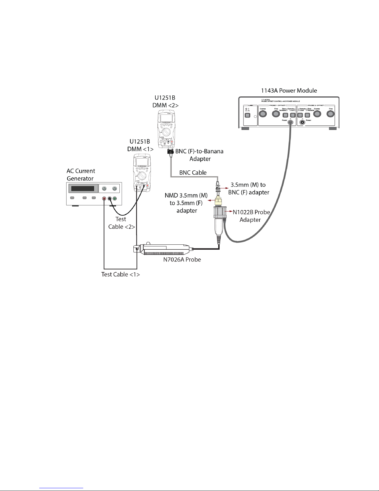
9 Set the DMM <2> to V
10 As displayed in Figure 12, connect a BNC cable to the:
a N1022B adapter’s output using the NMD 3.5mm (M) to 3.5mm (F) adapter and 3.5mm (M)
to BNC (F) adapter.
b DMM <2> using a BNC (F)-to-banana adapter.
This completes the test setup.
rms
mode.
N7026A 150 MHz AC/DC High Sensitivity Current Probes User’s Guide 33
Page 34
N7026A Probe
.
Figure 12 Complete Test Setup
11 Measure the current and record V
12 Calculate gain as follows:
Gain = V
Gain should be between 0.99 and 1.01 (+/-1% gain accuracy).
13 Remove the test cable and AC current generator from the N7026A probe.
* scale factor
rms
output of the probe as displayed on the DMM <2>.
rms
34 N7026A 150 MHz AC/DC High Sensitivity Current Probes User’s Guide
Page 35
Plots
N7026A Probe
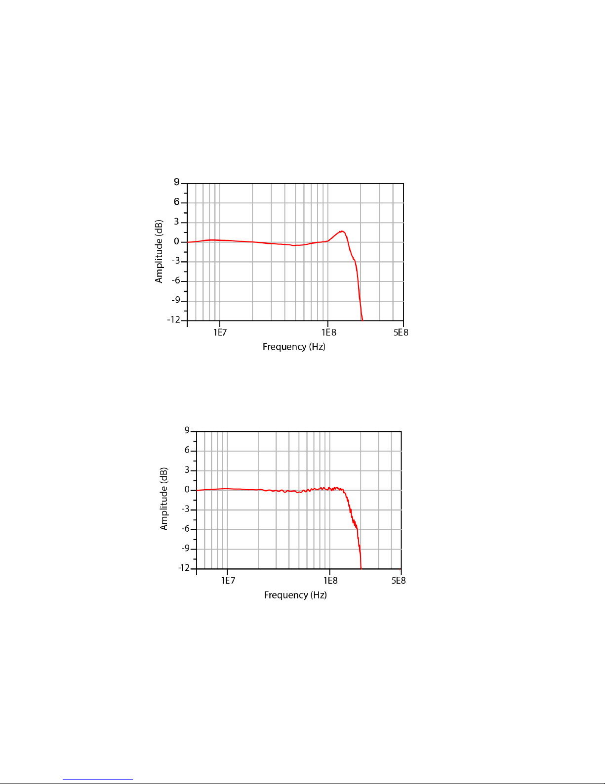
Figure 13 Frequency Response of N7026A for 1x Attenuation Mode
Figure 14 Frequency Response of N7026A for 5x Attenuation Mode
N7026A 150 MHz AC/DC High Sensitivity Current Probes User’s Guide 35
Page 36
N7026A Probe
Figure 15 Continuous Maximum Input Rating of N7026A
Figure 16 Insert Impedance of N7026A
36 N7026A 150 MHz AC/DC High Sensitivity Current Probes User’s Guide
Page 37
N7026A Probe
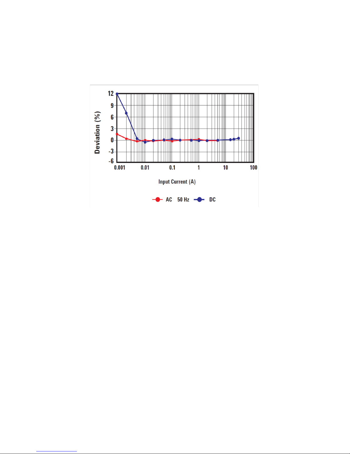
Figure 17 Amplitude Accuracy Characteristic of N7026A
N7026A 150 MHz AC/DC High Sensitivity Current Probes User’s Guide 37
Page 38
N7026A Probe
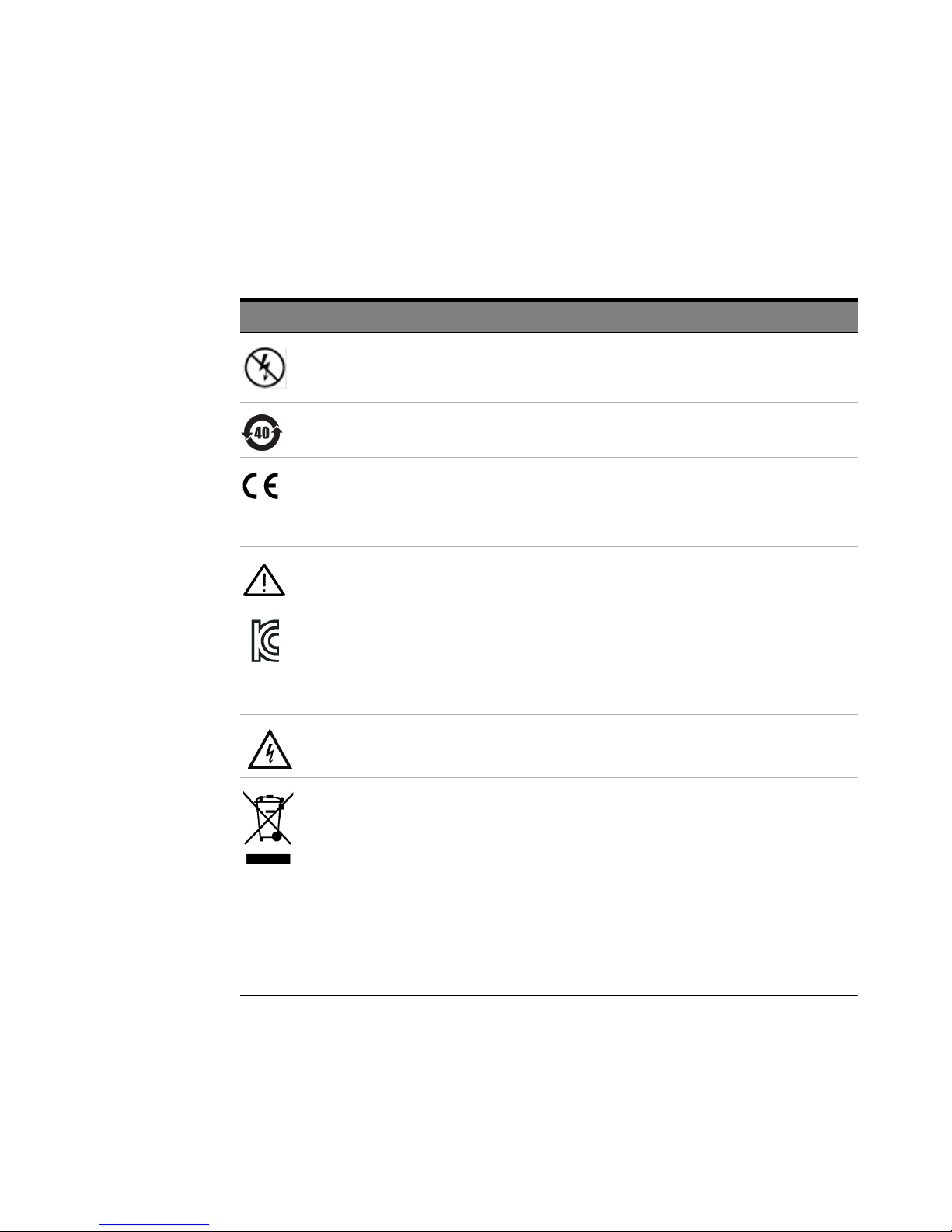
Product Markings and Labels
Table 7 Instrument Markings
Marking Description
Indicates that only insulated conductors suited to the voltage of the circuit
under test can be measured.
DO NOT use with an uninsulated conductor.
This symbol indicates the Environmental Protection Use Period (EPUP) for
the product’s toxic substances for the China RoHS requirements.
The CE mark is a registered trademark of the European Community.
ISM GRP 1-A denotes the instrument is an Industrial Scientific and Medical
Group 1 Class A product. ICES/NMB-001 indicates product compliance
with the Canadian Interference-Causing Equipment Standard.
The product is marked with this symbol when it is necessary for the user to
refer to the instructions in the documentation.
KC certification mark to demonstrate compliance with the South Korean
EMC requirements.
South Korean Class A EMC declaration This equipment is Class A suitable
for professional use and is for use in electromagnetic environments outside
of the home.
Indicates a risk of electric shock. Refer to the manual for more
information.
Notice for the European Community: This product complies with
the WEEE Directive (2002/96/EC) marking requirements. The
affixed label indicates that you must not discard this
electrical/electronic product in domestic household waste.
Product Category: With reference to the requirement types in the
WEEE Directive Annex I, this product is classed as a “Monitoring
and Control Instrumentation” product.
Do not dispose in domestic household waste.
To return unwanted products, contact your local Keysight office.
38 N7026A 150 MHz AC/DC High Sensitivity Current Probes User’s Guide
Page 39

Service Strategy
For calibration testing, return the probe to a Keysight Service Center. If the probe is under
warranty, normal warranty services apply. If the probe is not under warranty, repair costs
will be applied.
To return the Probe to Keysight Technologies for Service
Call (800) 829-4444 for further details and the location of your nearest Keysight
Technologies Service Office or go to www.keysight.com/find/assist for contact information.
1 Write the following information on a tag and attach it to the probe.
- Name and address of the owner
- Probe model number
- Description of service required or failure indications
2 Retain all accessories.
3 Return the probe in its case or pack the probe in foam or other shock-absorbing material
and place it in a strong shipping container. You can use the original shipping materials or
order materials from an Keysight Technologies Sales Office. If neither are available, place 3
to 4 inches of shock-absorbing material around the instrument and place it in a box that
does not allow movement during shipping.
4 Seal the shipping container securely.
5 Mark the shipping container as FRAGILE. In all correspondence, refer to the instrument by
model number and full serial number.
N7026A Probe
N7026A 150 MHz AC/DC High Sensitivity Current Probes User’s Guide 39
Page 40

N7026A Probe
40 N7026A 150 MHz AC/DC High Sensitivity Current Probes User’s Guide
Page 41

Index
Index
A
AC accuracy, 30
accuracy, 10
AutoProbe, 19
B
bushing, 23, 24
C
cable diameter, 11
calibration, 30
characteristics and specifications, 10
China RoHS requirements, 38
current direction indicator, 23
D
DC supply voltage requirements, 11
degauss, 26
demag, 26
demagnetizing switch, 8
dimensions (sensor), 11
dimensions output pod, 11
M
maximum altitude, 11
maximum cable diameter, 11
maximum current, 10
maximum peak current, 10
maximum rated power, 10
maximum relative humidity, 11
measurement procedure, 19
N
noise, 10
O
opening lever, 8
opening sensor head, 21
operating temperature range, 11
ow-sensitivity mode, 5
P
probe bandwidth, 10
probe power consumption, 11
probe sensitivity, 10
U
use, 11
using, 21
V
vertical scale, 10
W
weight, 11
Z
zero offset, 26
H
high frequencies, 23
high transient time signals, 5
high-sensitivity mode, 5
I
IEC 61010-1 Safety Standards, 15
impedance, insertion, 10
insertion impedance, 10
inspection, 13
instrument markings, 38
ISM1-A, 38
L
labels, 38
R
risetime, 10
S
safety warnings, 15
sensitivity, 10
sensor cable length, 11
sensor head, 8
service, 39
storage temperature range, 11
T
temperature coefficient, 10
temperature range, 11
N7026A 150 MHz AC/DC High Sensitivity Current Probes User’s Guide 41
Page 42

Index
42 N7026A 150 MHz AC/DC High Sensitivity Current Probes User’s Guide
 Loading...