

Page 1
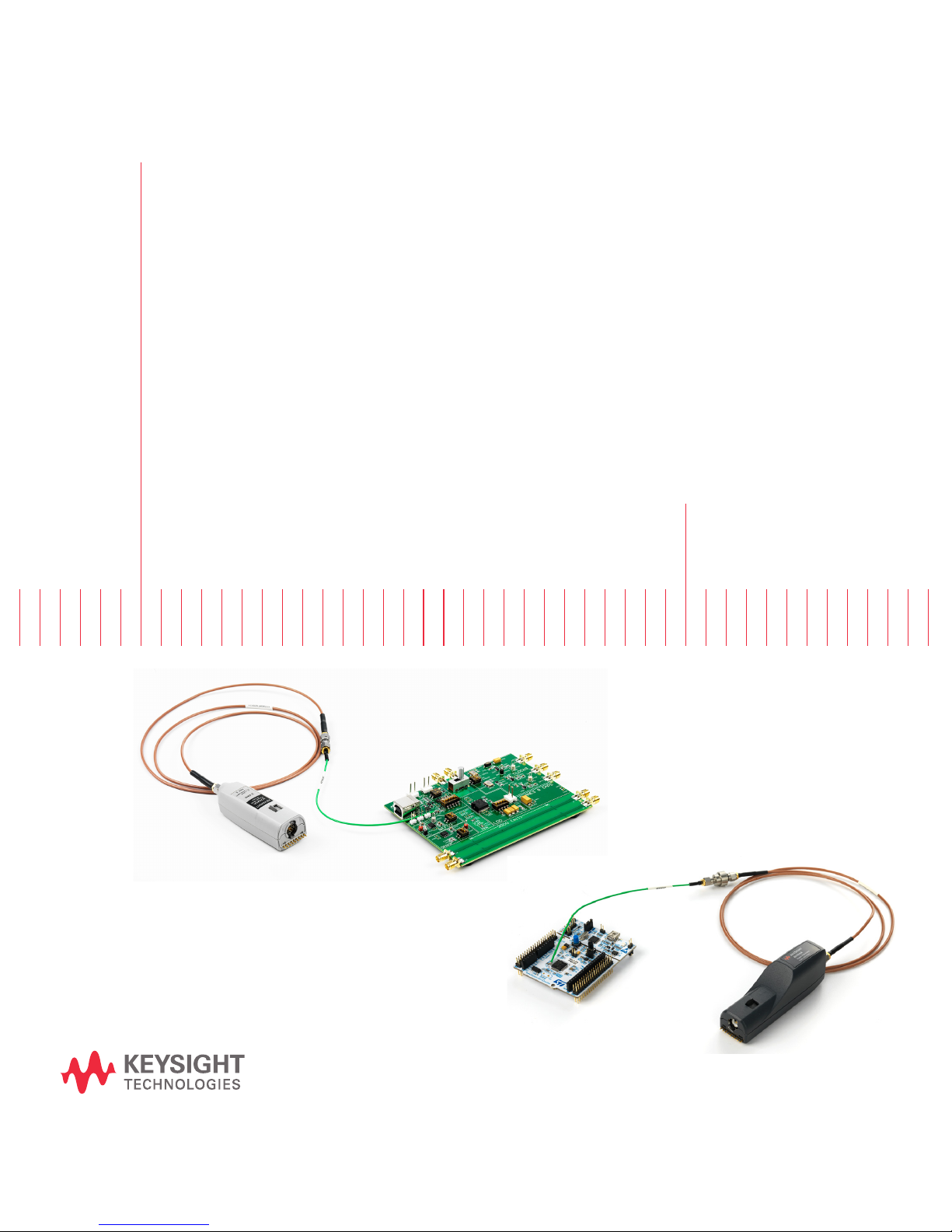
Keysight N7020A & N7024A
Power Rail Probes
User’s Guide
Page 2

Notices
CAUTION
WARNING
© Keysight Technologies 2014, 2015, 2017,
2018
No part of this manual may be reproduced in
any form or by any means (including electronic storage and retrieval or translation into
a foreign language) without prior agreement
and written consent from Keysight Technologies, Inc. as governed by United States and
international copyright laws.
Manual Part Number
N7020-97005
Edition
Sixth edition, August 2018
Published by:
Keysight Technologies
1400 Fountaingrove Parkway
Santa Rosa, CA, 95403
Warranty
The material contained in this document is
provided “as is,” and is subject to being
changed, without notice, in future editions.
Further, to the maximum extent permitted
by applicable law, Keysight disclaims all
warranties, either express or implied, with
regard to this manual and any information
contained herein, including but not limited
to the implied warranties of merchantability
and fitness for a particular purpose. Keysight shall not be liable for errors or for incidental or consequential damages in
connection with the furnishing, use, or performance of this document or of any information contained herein. Should Keysight
and the user have a separate written agreement with warranty terms covering the
material in this document that conflict with
these terms, the warranty terms in the separate agreement shall control.
Technology Licenses
The hardware and/or software described in
this document are furnished under a license
and may be used or copied only in accordance with the terms of such license.
U.S. Government Rights
The Software is "commercial computer software," as defined by Federal Acquisition Regulation ("FAR") 2.101. Pursuant to FAR
12.212 and 27.405-3 and Department of
Defense FAR Supplement ("DFARS")
227.7202, the U.S. government acquires
commercial computer software under the
same terms by which the software is customarily provided to the public. Accordingly,
Keysight provides the Software to U.S. government customers under its standard commercial license, which is embodied in its End
User License Agreement (EULA), a copy of
which can be found at
http://www.keysight.com/find/sweula. The
license set forth in the EULA represents the
exclusive authority by which the U.S. government may use, modify, distribute, or disclose
the Software. The EULA and the license set
forth therein, does not require or permit,
among other things, that Keysight: (1) Furnish technical information related to commercial computer software or commercial
computer software documentation that is not
customarily provided to the public; or (2)
Relinquish to, or otherwise provide, the government rights in excess of these rights customarily provided to the public to use,
modify, reproduce, release, perform, display,
or disclose commercial computer software or
commercial computer software documentation. No additional government requirements beyond those set forth in the EULA
shall apply, except to the extent that those
terms, rights, or licenses are explicitly
required from all providers of commercial
computer software pursuant to the FAR and
the DFARS and are set forth specifically in
writing elsewhere in the EULA. Keysight shall
be under no obligation to update, revise or
otherwise modify the Software. With respect
to any technical data as defined by FAR
2.101, pursuant to FAR 12.211 and 27.404.2
and DFARS 227.7102, the U.S. government
acquires no greater than Limited Rights as
defined in FAR 27.401 or DFAR 227.7103-5
(c), as applicable in any technical data.
52.227-14 (June 1987) or DFAR
252.227-7015 (b)(2) (November 1995), as
applicable in any technical data.
Safety Notices
A CAUTION notice denotes a hazard.
It calls attention to an operating
procedure, practice, or the like that,
if not correctly performed or
adhered to, could result in damage
to the product or loss of important
data. Do not proceed beyond a
CAUTION notice until the indicated
conditions are fully understood and
met.
A WARNING notice denotes a hazard. It calls attention to an operating procedure, practice, or the like
that, if not correctly performed or
adhered to, could result in personal
injury or death. Do not proceed
beyond a WARNING notice until the
indicated conditions are fully
understood and met.
2 N7020A and N7024A Power Rail Probes User’s Guide
Page 3

Contents
1 N7020A / N7024A Probes - Overview / 5
Introduction / 6
Probe Accessories / 9
Oscilloscope Compatibility / 16
2 General Information / 19
Inspecting the Probe / 20
Handling the Probe / 21
Cleaning the Probe / 22
Returning the Probe for Service / 23
Contacting Keysight Technologies / 24
3 Specifications and Characteristics / 25
N7020A Probe Specifications and Characteristics / 26
N7024A Probe Specifications and Characteristics / 30
4 Safety and Regulatory Information / 35
5 Using the Power Rail Probe / 39
Requirements for Optimum Probe Performance / 41
Connecting to the DUT / 44
Replacing N7023A Probe Browser Tips / 52
Avoiding Costly Repairs / 53
Common Types of Power Integrity Measurements / 55
6Calibrating/57
N7020A / N7024A Probe’s DC Attenuation/Offset Calibration Using N7022A
Main Cable / 58
N7020A and N7024A Power Rail Probes User’s Guide 3
Page 4

Contents
N7020A / N7024A Probe’s DC Attenuation/Offset Calibration Using
N7023A Probe Browser / 59
7Performance Plots/61
N7020A Performance Plots / 62
N7020A Input Impedance Equivalent Model / 66
N7024A Performance Plots / 68
N7024A Input Impedance Plots / 70
8 Performance Verification / 77
DC Input Resistance Performance Verification / 78
Bandwidth Performance Verification for N7024A Probe / 81
Index
4 N7020A and N7024A Power Rail Probes User’s Guide
Page 5

Keysight N7020A and N7024A Power Rail Probes
User’s Guide
1 N7020A / N7024A Probes -
Overview
Introduction 6
Probe Accessories 9
Oscilloscope Compatibility 16
5
Page 6
1 N7020A / N7024A Probes - Overview
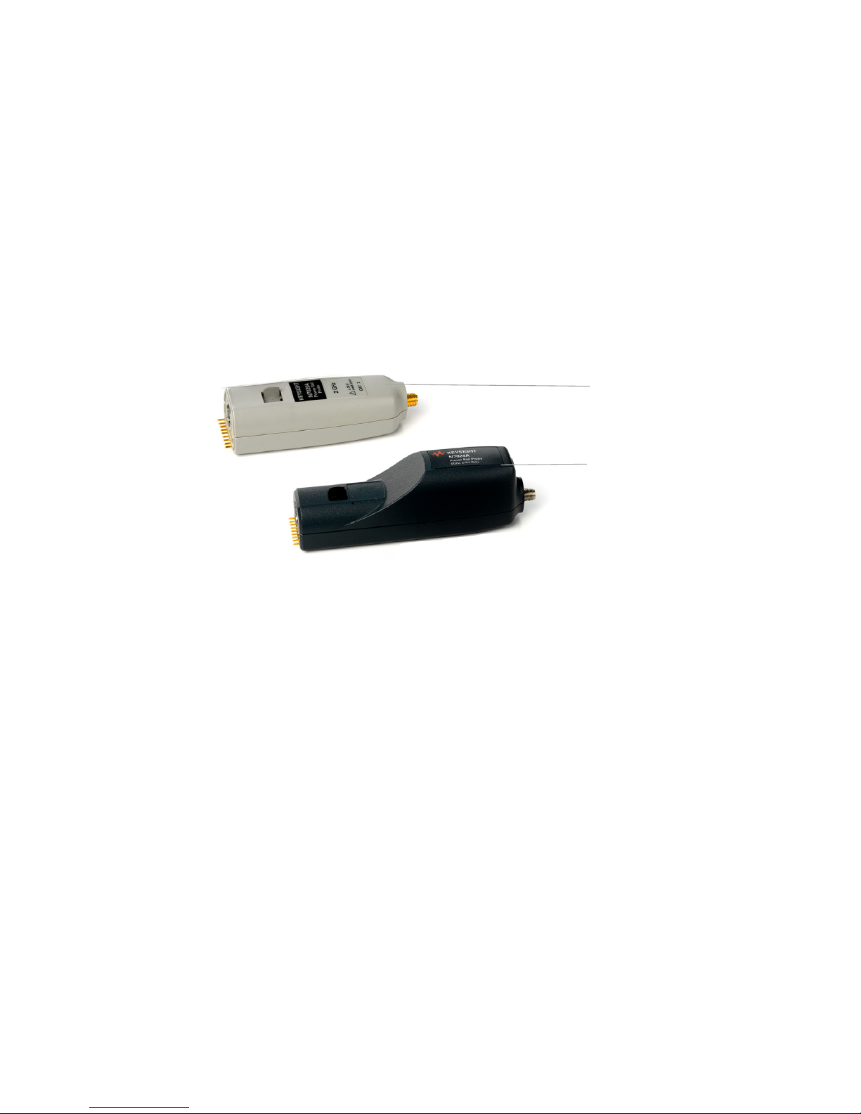
N7024A Probe
N7020A Probe
Introduction
In this guide, the following two probes in the power rail probing category are
described.
• N7020A 2 GHz Power Rail Probe
• N7024A 6 GHz Power Rail Probe
These probes are designed for power integrity measurements such as Periodic and
Random Disturbances (PARD), static and dynamic load response, and
programmable power-rail response.
These probes have an output connector with the Keysight AutoProbe 1 interface
that allows these probes to connect directly to a compatible Keysight oscilloscope
(see page 16). The oscilloscope’s AutoProbe interface provides the probe power,
probe offset, and auto configuration of probe type and attenuation setting on
connection.
A variety of accessories are shipped with these probes to suit various DUT
connection scenarios and to make the connection to DUT possible in the most
difficult to reach situations as well (see page 44).
These probes provide the following advantages:
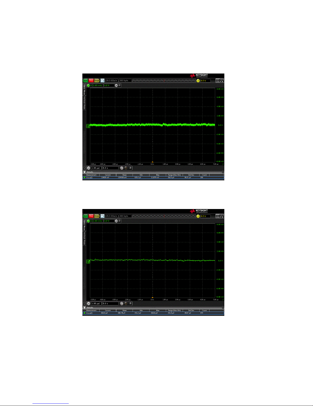
• Low noise due to a low attenuation ratio and 50Ω output. See Figure 1 and
Figure 2 on page 8.
• A large probe offset range. The offset allows small signals (~1 mV), that exist on
top of a DC supply, to be centered on an oscilloscope screen for maximum
vertical sensitivity.
• Low DC loading due to a 50 kΩ input impedance at DC.
6 N7020A and N7024A Power Rail Probes User’s Guide
Page 7
N7020A / N7024A Probes - Overview 1
NOTE
CAUTION
• Large active signal range in addition to the offset range
While the N7020A and N7024A probes have a number of features in common, the N7024A
probe is an extension to the capabilities and performance of the N7020A probe. When
compared to the N7020A probe, the N7024A probe provides enhanced features such as:
> higher bandwidth (upto 6 GHz)
> compatibility with high-end Keysight oscilloscopes (V-series and Z-series)
> improved usability and browsing capabilities
> unique s parameters stored in each N7024A probe for maximum accuracy
Before using these probes, refer to “Safety and Regulatory Information" on page 35.
Handle the probes with care and refer to the safety notices in this manual. Avoid any
mechanical shocks to these products to guarantee accurate performance and protection.
N7020A and N7024A Power Rail Probes User’s Guide 7
Page 8
1 N7020A / N7024A Probes - Overview
Figure 1 Example of Measured Mean Noise at 2 GHz BW: 1.04369 mV
Figure 2 Example of Measured Mean Noise at 20 MHz BW: 443.74 mV
p-p
p-p
8 N7020A and N7024A Power Rail Probes User’s Guide
Page 9
Probe Accessories
Standard Accessories
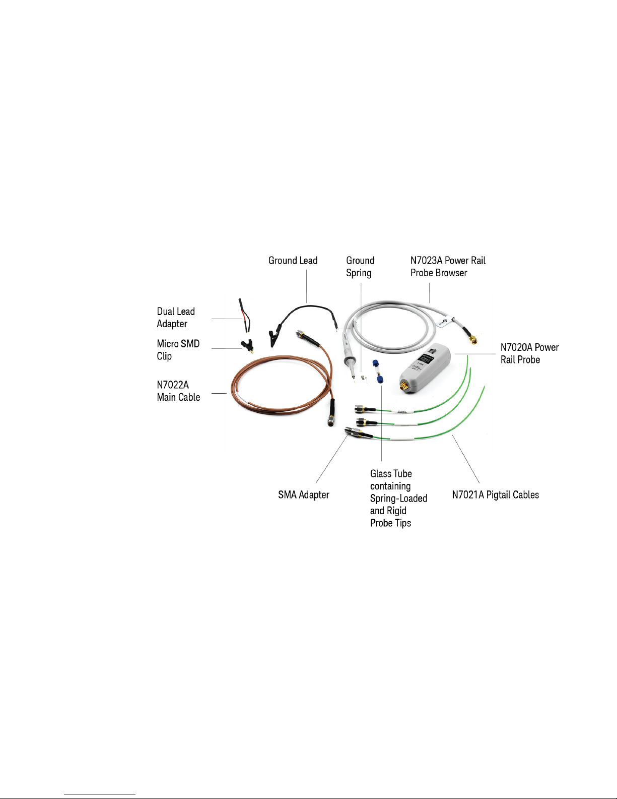
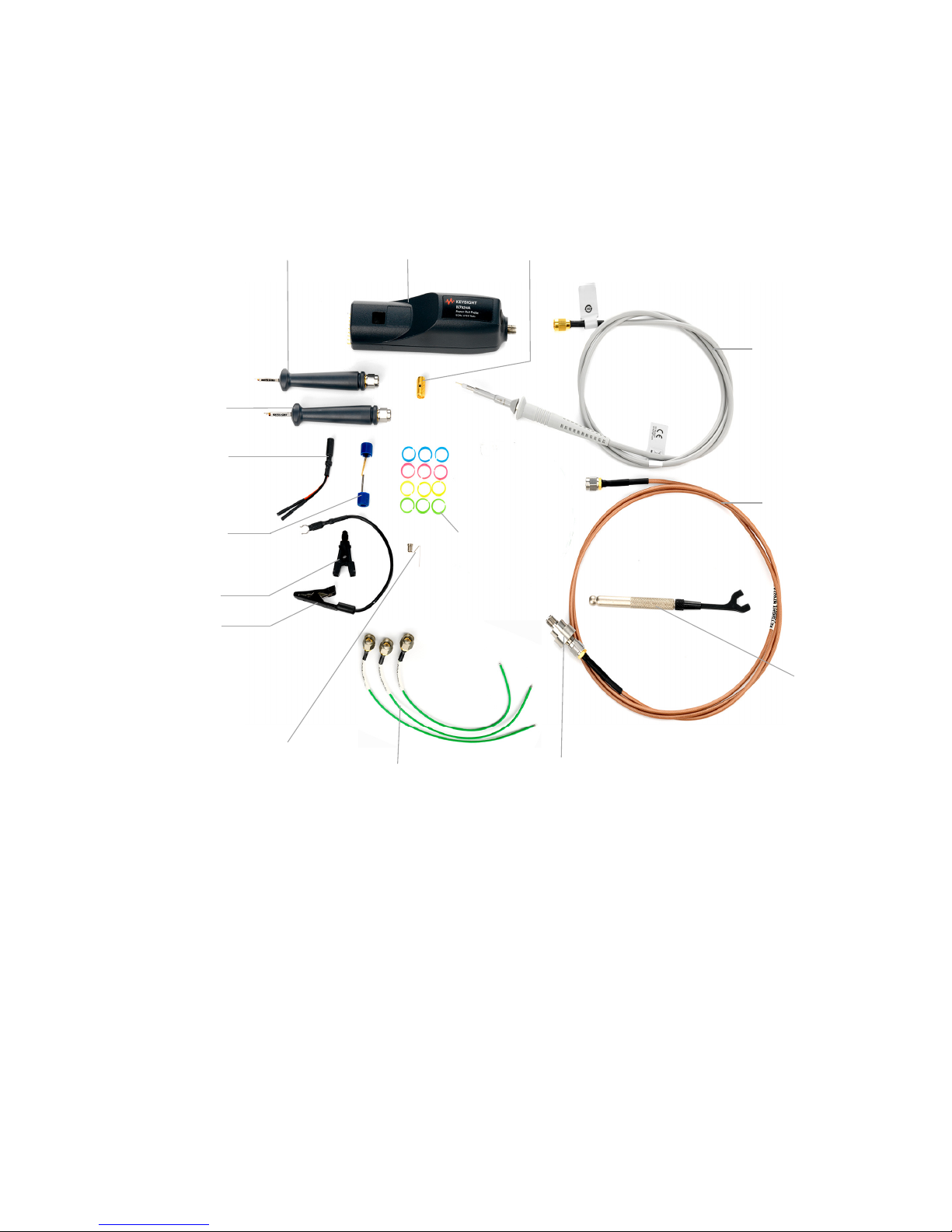
The N7020A and N7024A probes are shipped with the accessories shown in
Figure 3 and Figure 4 respectively. These standard accessories are described in
Table 1.
N7020A / N7024A Probes - Overview 1
Figure 3 N7020A Probe with Standard Accessories
N7020A and N7024A Power Rail Probes User’s Guide 9
Page 10
1 N7020A / N7024A Probes - Overview
N7024A Probe
N7033A Probe
Browser
N7032A Probe
Browser
Dual Lead Adapter
N7021A Pigtail
Cables
N7022A Main
Cable
Wrench
N7023A Probe
Browser
Ground Lead
Micro SMD Clip
Rotating
Adapter
Ground
Spring
SMA Adapter
Glass Tube containing
Spring-loaded and
Rigid Probe Tips
Color Coding
Rings
10 N7020A and N7024A Power Rail Probes User’s Guide
Figure 4 N7024A Probe with Standard Accessories
Page 11
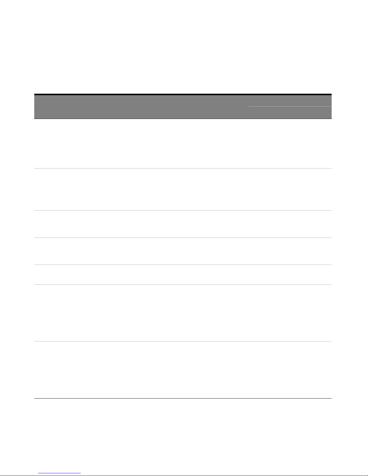
Table 1 Standard Accessories
N7020A / N7024A Probes - Overview 1
Accessories Quantity
Supplied
N7021A Pigtail Cables 3 Coaxial cables designed to be soldered onto the
DUT and connected to the probe via the main
cable.
Refer to the topic “Using the N7021A Pigtail
Cable and N7022A Main Cable" on page 46 to
know more.
N7022A Main Cable 1 Coaxial cable that you can use to establish
connectivity between the probe and DUT in
multiple ways such as direct connection to DUT,
connection via pigtail cables, or connection via
N7033A / N7034A probe browsers.
SMA Adapter 1 Used to connect the main cable to:
- the pigtail cable.
- the N7032A / N7033A probe browser.
Rotating Adapter 1 Used to connect the main cable to:
- the pigtail cable.
- the N7032A / N7033A probe browser.
Wrench 1 Used to effectively grip and tighten the smaller
side of the rotating adapter.
Description Shipped with
N7020A Probe N7024A Probe
✓✓
✓✓
✓✓
✓
✓
N7032A Power Rail
Probe Browser
N7033A Power Rail
Probe Browser
1 Browser based on .086" semi-rigid coax that has
an approximate fixed span of .055" for probing
0603 and 0805 SMT parts.
NOTE: Though this browser is not shipped as a
standard accessory with the N7020A probe, you
can order it separately for use with the N7020A
probe.
1 Browser based on .047" semi-rigid coax that has
an approximate fixed span of .035" for probing
0201 and 0402 SMT parts.
NOTE: Though this browser is not shipped as a
standard accessory with the N7020A probe, you
can order it separately for use with the N7020A
probe.
✓
✓
N7020A and N7024A Power Rail Probes User’s Guide 11
Page 12
1 N7020A / N7024A Probes - Overview
Table 1 Standard Accessories
Accessories Quantity
Supplied
N7023A Power Rail
Probe Browser
N7023A Browser Accessories
(N7023A bowser is shipped with the following accessories.)
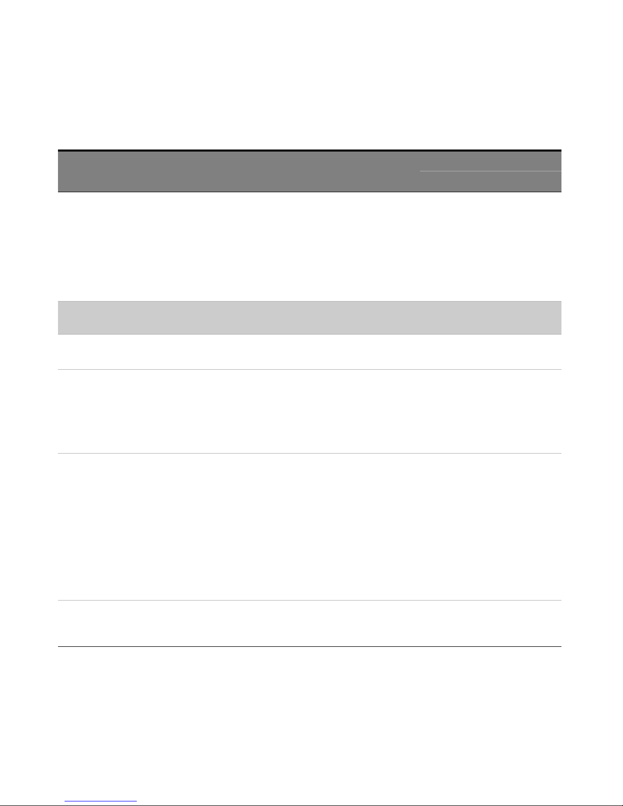
Ground Spring 2.5 mm 1 Provides the highest performance connection for
Ground Lead 15 cm 1 Used to reach grounding locations that are
1 Provides a convenient way to probe the power
rails with a number of accessories available for
connection to DUT. The trade-off for this
convenience is the lower signal fidelity than the
N7021A pigtail cables or the N7022A main cable
or other two supported browsers. Mechanically,
this browser is similar to a traditional passive
probe and is used in the same manner.
the N7023A probe browser.
farther away from the probing location than can
be reached by the ground spring. However, the
longer lead means it has a larger inductance in
the ground return path which corresponds to a
lower performance than using the ground spring.
Description Shipped with
N7020A Probe N7024A Probe
✓✓
✓✓
✓✓
Spring-loaded Probe
Tips
Rigid Probe Tips 2 Replaceable probe tips. To know how to replace
3 Allows you to probe signals with less
susceptibility to vibration or movement than
traditional rigid tips. The spring loaded tips work
when they are either partially or fully compressed
and are protected against over compression
damage.
Note: One spring-loaded tip is pre-installed by
Keysight into the N7023A browser.
These tips are replaceable. To know how to
replace these tips, refer to “Replacing N7023A
Probe Browser Tips" on page 52.
these tips, refer to “Replacing N7023A Probe
Browser Tips" on page 52.
✓✓
✓✓
12 N7020A and N7024A Power Rail Probes User’s Guide
Page 13
Table 1 Standard Accessories
N7020A / N7024A Probes - Overview 1
Accessories Quantity
Supplied
Dual Lead Adapter 1 Allows you to easily connect the N7023A browser
to the popular 0.1” pin headers with 0.025”
square pins. This dual lead adapter has no
shorting hazards since all external metal surfaces
are insulated.
Micro SMD Clip
(Surface Mount Grabber)
Protection Cap 2.5 mm 1 Provides a protective cover to the browser when
Color Coding Rings 3x4 colors Used to keep track of which probe is connected to
1 Provides fast and convenient hands-free probing
of surface mount capacitors. The Micro SMD clip
is used in conjunction with the dual lead adapter.
It is a best practice to twist the leads off the dual
lead adapter to reduce coupling of external noise
into the probe.
not in use.
which channel input on your oscilloscope. Place
one ring on the probe cable near the oscilloscope
input and place another ring of the same color
near the probe head. This ensures that you can
pick up a probe and immediately know which
channel it is connected to without having to track
the cable back to the oscilloscope channel input.
Description Shipped with
N7020A Probe N7024A Probe
✓✓
✓✓
✓✓
✓✓
N7020A and N7024A Power Rail Probes User’s Guide 13
Page 14
1 N7020A / N7024A Probes - Overview
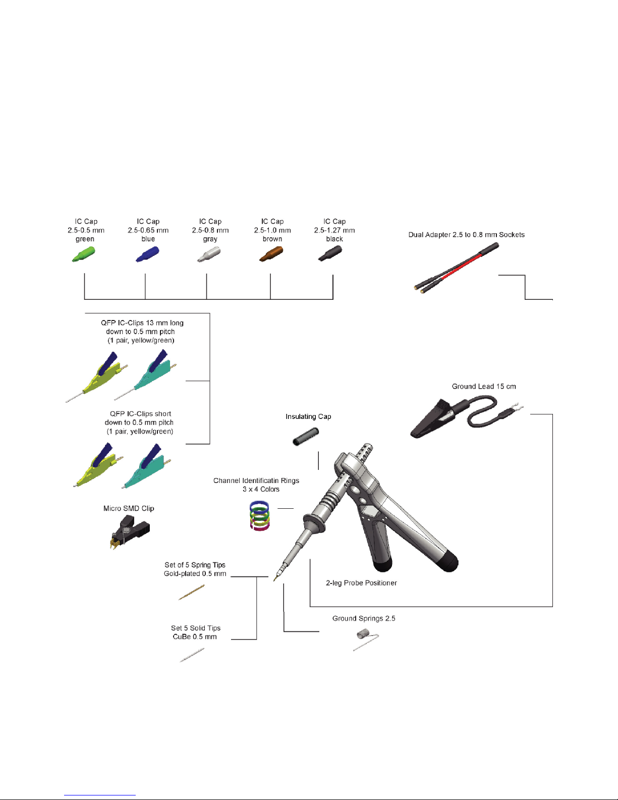
Optional Orderable Accessories
Besides the standard accessories that are shipped with the probes, a number of
optional accessories are also available that you can order separately. These
optional accessories are shown in this picture and briefly described in Table 2 on
page 15.
14 N7020A and N7024A Power Rail Probes User’s Guide
Page 15
N7020A / N7024A Probes - Overview 1
Table 2 Orderable Accessories
Optional Accessory Quantity Accessory P/N Keysight Product
Number
IC Cap 2.5 - 0.5 mm green 3 0960-2983 -
IC Cap 2.5 - 0.65 mm blue 3 0960-2984 -
IC Cap 2.5 - 0.8 mm gray 3 0960-2988 -
IC Cap 2.5 - 1.0 mm brown 3 0960-2989 -
IC Cap 2.5 - 1.27 mm black 3 0960-2986 -
Insulating Cap 2.5 mm 1 0960-2985 -
Ground Spring 2.5 mm 3 0960-2980 N4838A
Set of 5 Spring Tips Gold-plated 0.5 mm1 0960-2981 -
Set of 5 Solid tips CuBe 0.5 mm 1 0960-2979 -
Dual adapter 2.5 to
0.8 mm sockets
QFP IC-Clips 13 mm long down o
0.5 mm pitch (1 pair yellow/green)
QFP IC-Clips short down to 0.5 mm
pitch (1 pair yellow/green)
Ground Lead 15 cm 1 0960-2906 N4837A
2-leg Probe Positioner 1 N2786-60001 N2786A
Micro SMD Clip 1 1400-3652 -
1 0960-2898 N4836A
2 0960-2992 -
2 0960-2995 -
N7020A and N7024A Power Rail Probes User’s Guide 15
Page 16
1 N7020A / N7024A Probes - Overview
NOTE
Oscilloscope Compatibility
The N7020A and N7024A probes are designed for Keysight oscilloscopes with 50Ω
AutoProbe-interface channel inputs.
The N7020A and N7024A probes are compatible with the Keysight oscilloscopes
shown in Table 3 and Table 4. The tables also list the minimum required firmware
version to support these probes.
Table 3 Compatible Oscilloscopes for the N7020A Probe
Oscilloscopes Required
S-Series ≥ 5.20
9000 Series ≥ 5.20
9000A ≥ 5.20
6000 X-Series ≥ 6.10
Firmware Version
4000 X-Series ≥ 4.00
3000T X-Series ≥ 4.00
3000A-X-Series ≥ 2.39
Table 4 Compatible Oscilloscopes for the N7024A Probe
Infiniium Oscilloscopes Required
Firmware Version
S-Series ≥ 06.20.00803
V-Series
(with N5442A adapter)
Z-Series
(with N5442A adapter)
16 N7020A and N7024A Power Rail Probes User’s Guide
Page 17

N7020A / N7024A Probes - Overview 1
Is Your Oscilloscope Software Up-to-Date? Keysight periodically releases software
updates to support your probe, fix known defects, and incorporate product
enhancements. To download the latest firmware, go to www.keysight.com and
search for your oscilloscope’s topic. Click on the “Drivers, Firmware & Software”
tab.
N7020A and N7024A Power Rail Probes User’s Guide 17
Page 18

1 N7020A / N7024A Probes - Overview
18 N7020A and N7024A Power Rail Probes User’s Guide
Page 19

Keysight N7020A and N7024A Power Rail Probes
User’s Guide
2 General Information
Inspecting the Probe 20
Handling the Probe 21
Cleaning the Probe 22
Returning the Probe for Service 23
Contacting Keysight Technologies 24
19
Page 20

2 General Information
WARNING
CAUTION
Inspecting the Probe
• Inspect the shipping container for damage.
Keep the damaged shipping container or cushioning material until the contents
of the shipment have been checked for completeness and the probe has been
checked mechanically and electrically.
• Check the accessories.
• If the contents are incomplete or damaged, notify your Keysight Technologies
Sales Office.
• Inspect the probe. If there is mechanical damage or defect, or if the probe does
not operate properly or pass calibration tests, notify your Keysight Technologies
Sales Office.
If the shipping container is damaged, or the cushioning materials show signs of
stress, notify the carrier as well as your Keysight Technologies Sales Office. Keep
the shipping materials for the carrier’s inspection. The Keysight Technologies
office will arrange for repair or replacement at Keysight Technologies’ option
without waiting for claim settlement.
Must be Grounded. Before making connections to the input leads of this probe, ensure
that the probe’s output connector is attached to the channel input of the oscilloscope
and the oscilloscope is properly grounded.
To protect against electrical shock, use only the accessories supplied with this probe or in
the accessory kit.
20 N7020A and N7024A Power Rail Probes User’s Guide
Page 21
Handling the Probe
CAUTION
WARNING
CAUTION
Handle the probe with care to avoid injury, especially when it is fitted with the
extra thin and sharp spring contact tip.
The browser cable is a sensitive part of the N7023A power rail probe browser and,
therefore, you should be careful not to damage it through excessive bending or pulling.
You should also avoid any mechanical shocks to this product in order to guarantee
accurate performance and protection.
Periodically inspect the probe wires and cables to check for any damage. The probe
must NOT BE USED if there are any signs of damage.
If the N7022A main cable is damaged, it may cause the N7024A probe to not meet its
warranted bandwidth specification of 6 GHz. It is recommended to verify the cable using
the procedure described in “To verify if the N7022A main cable is damaged" on page 87.
General Information 2
N7020A and N7024A Power Rail Probes User’s Guide 21
Page 22

2 General Information
Cleaning the Probe
If the probe requires cleaning:
1 Disconnect the probe from the oscilloscope, external power supply, and any circuit
under test.
2 Gently clean the probe with a soft cloth dampened with a mild soap and water
solution.
3 Wipe with clean water to remove the detergent and then dry thoroughly with a
clean cloth.
4 Make sure that the probe is completely dry before reconnecting it to an
oscilloscope.
22 N7020A and N7024A Power Rail Probes User’s Guide
Page 23
Returning the Probe for Service
NOTE
NOTE
If the probe is found to be defective we recommend sending it to an authorized
service center for all repair and calibration needs. Perform the following steps
before shipping the probe back to Keysight Technologies for service.
1 Contact your nearest Keysight sales office for information on obtaining an RMA
number and return address.
2 Write the following information on a tag and attach it to the malfunctioning
equipment.
• Name and address of owner
• Product model number (for example, N7024A)
• Product Serial Number (for example, MYXXXXXXXX)
• Description of failure or service required.
Include probing and browsing heads if you feel the probe is not meeting performance
specifications or a yearly calibration is requested.
General Information 2
3 Protect the probe by wrapping in plastic or heavy paper.
4 Pack the probe in the original carrying case or if not available use bubble wrap or
packing peanuts.
5 Place securely in sealed shipping container and mark container as "FRAGILE".
If any correspondence is required, refer to the product by serial number and model number.
N7020A and N7024A Power Rail Probes User’s Guide 23
Page 24

2 General Information
Contacting Keysight Technologies
For technical assistance, contact your local Keysight Call Center.
• In the Americas, call 1 (800) 829-4444
• In other regions, visit http://www.keysight.com/find/assist
• Before returning an instrument for service, you must first call the Call Center at
1 (800) 829-4444.
24 N7020A and N7024A Power Rail Probes User’s Guide
Page 25

Keysight N7020A and N7024A Power Rail Probes
NOTE
User’s Guide
3 Specifications and
Characteristics
N7020A Probe Specifications and Characteristics 26
N7024A Probe Specifications and Characteristics 30
The tables in this chapter list the specifications and characteristics for the N7020A
and N7024A probes.
All entries included in this chapter are characteristics unless otherwise
noted.
Input Impedance DC is the only warranted specification for the N7020A
probe.
Bandwidth (for the probe) and Input Impedance DC are the only
warranted specifications for the N7024A probe.
25
Page 26
3 Specifications and Characteristics
N7020A Probe Specifications and Characteristics
Table 5 N7020A Environmental Specifications
Attribute Specification
With N7021A Pigtail Cable / N7022A Main Cable
Use For indoor use only
Temperature Operating: –10 °C to +55 °C (probe pod)
Non-operating: –40 °C to +70 °C (probe pod)
Operating: –40 °C to +85 °C (main cable/pigtail
cable)
Non-operating: –40 °C to +85 °C (main
cable/pigtail cable)
Altitude Operating: 3,000 m (9,842 feet)
Non-operating: 15,300 m (50,196 feet)
Humidity Operating: 25 – 85% room humidity
Non-operating: 25 – 85% room humidity
Pollution Degree Pollution Degree 2
With N7023A / N7032A / N7033A Browser
Operating: –10 °C to +55 °C (browser)
Non-operating: –40 °C to +70 °C (browser)
Operating: 3,000 m (9,842 feet)
Non-operating: 15,300 m (50,196 feet)
Operating: 80% room humidity for
temperatures up to 31 °C, decreasing linearly to
Non-operating: 95% room humidity for
temperatures up to 40 °C
Specification
40% at 50 °C
26 N7020A and N7024A Power Rail Probes User’s Guide
Page 27
NOTE
A few electrical specifications and characteristics of the probe vary based on the connection
mechanism used to connect the probe to DUT. This variation is listed in the table below. To
know about these connection mechanisms, see “Connecting to the DUT" on page 44.
Table 6 N7020A Electrical Characteristics and Specifications
Characteristics (based on probe’s connection configuration)
Specifications and Characteristics 3
Attribute
Probe Bandwidth (–3 dB) 2 GHz 2 GHz 350 MHz (using
Maximum Input Voltage
(non-destructive)
Attenuation Ratio 1.1:1
Offset Range ± 24V
Input Impedance at DC
Active Signal Range ± 850 mV (about offset voltage)
Probe Noise (at 2 GHz) 10% increase in the noise of the connected oscilloscope
Output Termination 50 Ω scope input
Probe Type Single Ended
* Warranted specification.All other characteristics are typical.
*
With N7022A
Main Cable
With N7021A
Pigtail Cable &
N7022A Main
Cable
With N7023A
Browser
the included
ground spring)
±30V peak input
(mains isolated)
50 kΩ ±2%
With N7032A
Browser &
N7022A Main
Cable
2 GHz 2 GHz
With N7033A
Browser &
N7022A Main
Cable
Table 7 Mechanical Characteristics of N7020A Probe and Browsers
Description N7020A Probe N7023A Browser N7032A Browser N7033A Browser
Weight 50 g 26 g 10 g 10 g
Dimensions See Figure 5 on page 29 for dimensions.
N7020A and N7024A Power Rail Probes User’s Guide 27
Page 28

3 Specifications and Characteristics
Table 8 Safety Specifications of N7020A Power Rail Probe
Specification
IEC61010-031
For a description of safety markings and symbols on the probe, refer to the
chapter “Safety and Regulatory Information" on page 35.
28 N7020A and N7024A Power Rail Probes User’s Guide
Page 29
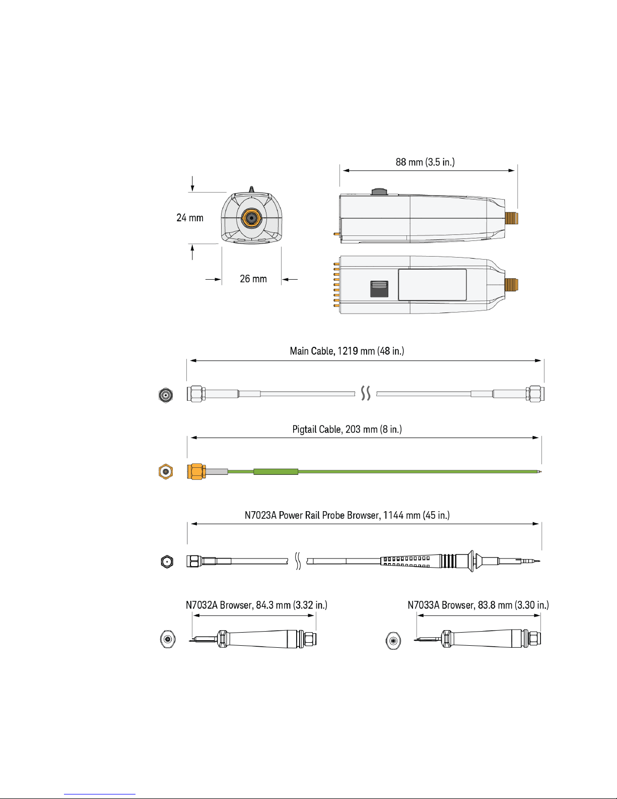
Specifications and Characteristics 3
N7020A Probe, Browsers, and Cables Dimensions
Figure 5 N7020A Probe, Browsers, and Accessory Cables Dimensions
N7020A and N7024A Power Rail Probes User’s Guide 29
Page 30
3 Specifications and Characteristics
N7024A Probe Specifications and Characteristics
Table 9 N7024A Environmental Specifications
Attribute Specification
With N7022A Main Cable / N7021A Pigtail Cable
Use For indoor use only
Temperature Operating: –10 °C to +55 °C (probe pod)
Non-operating: –40 °C to +70 °C (probe pod)
Operating: –40 °C to +85 °C (main cable/pigtail
cable)
Non-operating: –40 °C to +85 °C (main
cable/pigtail cable)
Altitude Operating: 4600 m (15,092 feet)
Non-operating: 15,300 m (50,196 feet)
Humidity Operating: 25 – 85% room humidity
Non-operating: 25 – 85% room humidity
Pollution Degree Pollution Degree 2
With N7023A / N7032A / N7033A Browser
Operating: –10 °C to +55 °C (browser)
Non-operating: –40 °C to +70 °C (browser)
Operating: 4600 m (15,092 feet)
Non-operating: 15,300 m (50,196 feet)
Operating: 80% room humidity for
temperatures up to 31 °C, decreasing linearly to
Non-operating: 95% room humidity for
Specification
40% at 50 °C
temperatures up to 40 °C
30 N7020A and N7024A Power Rail Probes User’s Guide
Page 31
NOTE
A few electrical specifications and characteristics of the probe vary based on the connection
mechanism used to connect the probe to DUT. This variation is listed in the table below. To
know about these connection mechanisms, refer “Connecting to the DUT" on page 44.
Table 10 N7024A Probe Electrical Characteristics and Specifications
Characteristics (based on probe’s connection configuration)
Specifications and Characteristics 3
For the
Attribute
Probe Bandwidth (–3 dB) 6 GHz * 6 GHz 5 GHz 350 MHz 4 GHz 5 GHz
Maximum Input Voltage
(non-destructive)
Attenuation Ratio 1.3:1
Risetime (10 to 90%)
Calculated as:
tr = .435/bandwidth
Risetime (20 to 80%)
Calculated as:
tr = .676 * 10/90 tr
Offset Range ± 15.25V
Input Impedance at DC
Active Signal Range ± .6V (1.2Vpp)
N7024A
Probe Only
*
Probe with
N7022A Main
Cable
73pS 87pS 1.24nS 109pS 87pS
49pS 59pS .84nS 74pS 59pS
Probe with
N7021A Pigtail
Cable &
N7022A Main
Cable
±15V peak input
(mains isolated)
50 kΩ ±2%
Probe with
N7023A
Browser
Probe with
N7032A
Browser &
N7022A
Main Cable
Probe with
N7033A
Browser &
N7022A
Main Cable
Probe + Oscilloscope
Noise
Output Termination 50 Ω scope input
Probe Type Single Ended
* Warranted specification. All other characteristics are typical.
N7020A and N7024A Power Rail Probes User’s Guide 31
30% increase in the noise of the connected oscilloscope
Page 32
3 Specifications and Characteristics
Table 11 Mechanical Characteristics of the N7024A Probe and Browsers
Description N7024A Probe N7023A Browser N7032A Browser N7033A Browser
Weight 155 g 26 g 10 g 10 g
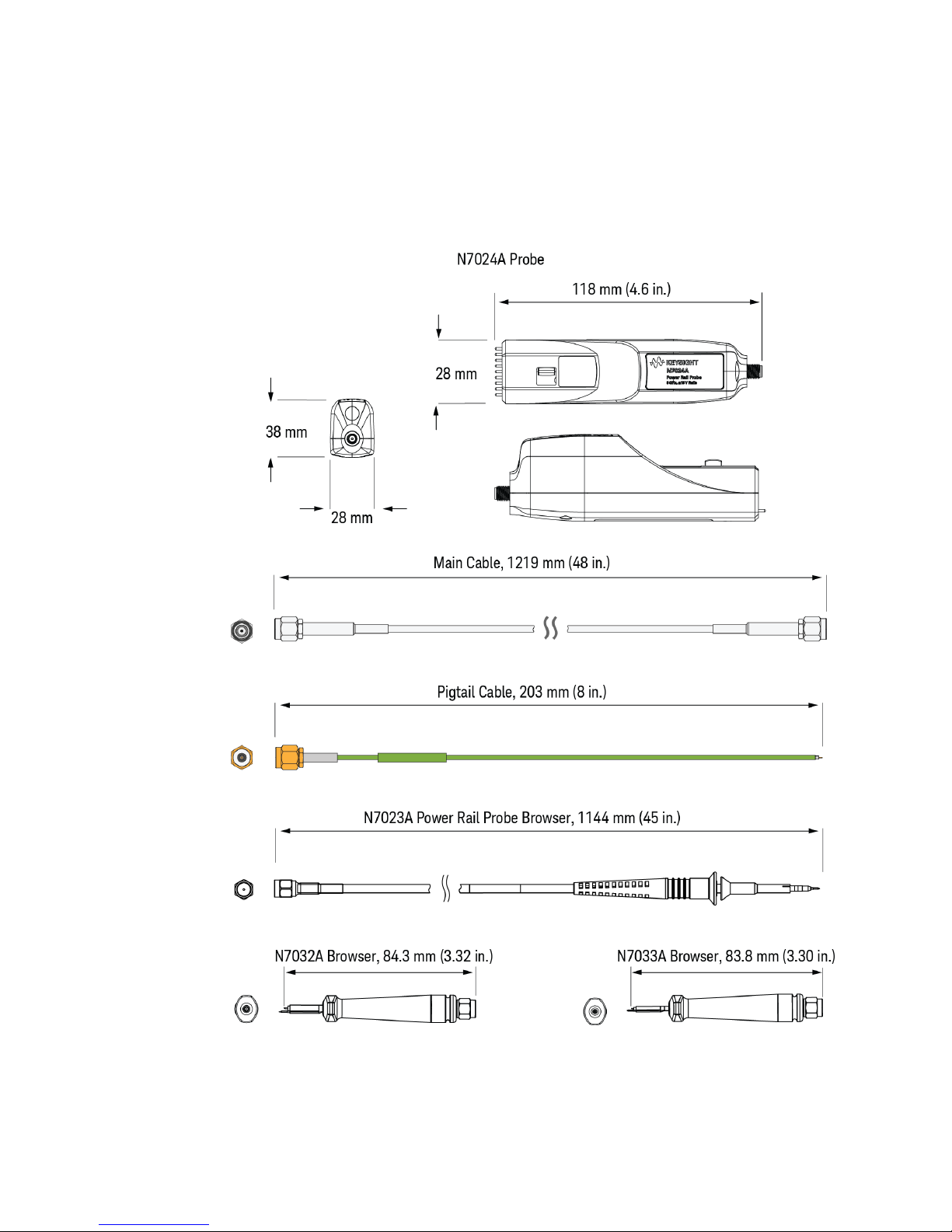
Dimensions See Figure 6 on page 33 for dimensions.
Table 12 Safety Specifications of N7024A Probe
Specification
IEC61010-031
For a description of safety markings and symbols on the probe, refer to the
chapter “Safety and Regulatory Information" on page 35.
32 N7020A and N7024A Power Rail Probes User’s Guide
Page 33
Specifications and Characteristics 3
N7024A Probe, Cables, and Browsers Dimensions
Figure 6 N7024A Probe, Browsers, and Accessory Cables Dimensions
N7020A and N7024A Power Rail Probes User’s Guide 33
Page 34

3 Specifications and Characteristics
34 N7020A and N7024A Power Rail Probes User’s Guide
Page 35
Keysight N7020A and N7024A Power Rail Probes
WARNING
CAUTION
WARNING
User’s Guide
4 Safety and Regulatory
Information
These probes have been designed and tested in accordance with accepted
industry standards, and have been supplied in a safe condition.
Throughout this manual and specifically in this chapter, there are warnings,
cautions, and notes that must be followed by the user to ensure safe operation
and to maintain the product in a safe condition. If the probe is used in a manner
not specified by the manufacturer, the protection provided by the equipment may
be impaired.
Also, note the external markings on the probe that are described in this document.
To avoid personal injury and to prevent fire or damage to this product or
products connected to it, review and comply with the following safety
precautions. Be aware that if you use this probe assembly in a manner not
specified, the protection this product provides may be impaired.
These probes are for use only on circuits that are not directly connected to mains.
Do not use the probe for measurements on mains circuits.
Use Only Grounded Instruments.
Do not connect the probe’s ground lead to a potential other than earth ground.
Always make sure the probe and oscilloscope are grounded properly. Before
making connections to the input leads of this probe, ensure that the probe’s
output connector is attached to the channel input of the oscilloscope and the
oscilloscope is properly grounded.
35
Page 36
4 Safety and Regulatory Information
WARNING
WARNING
WARNING
WARNING
WARNING
WARNING
WARNING
WARNING
Connect and Disconnect Properly.
Connect the probe to the oscilloscope and connect the ground lead to earth ground
before connecting the probe to the circuit under test. Disconnect the probe input and
the probe ground lead from the circuit under test before disconnecting the probe from
the oscilloscope.
Do Not Operate Without Covers. To avoid electrical shock or fire hazard, do not operate
this probe with the covers removed.
Avoid Exposed Circuit. To avoid injury, remove jewelry such as rings, watches, and other
metallic objects. Do not touch exposed connections and components when power is
present.
For Indoor Use Only. Do not operate in wet / damp environments to avoid electric shock.
Keep product surfaces dry and clean. Do not operate in an explosive environment.
Do Not Operate With Suspected Failures. If you suspect there is damage to this probe,
have it inspected by a qualified service personnel.
Periodically inspect the probe wires and cables to check for any damage. The probe
must NOT BE USED if there are any signs of damage.
Concerning the Oscilloscope or Voltage Measuring Instrument to Which
the Probe is Connected
Whenever it is likely that the ground protection is impaired, you must make the
instrument inoperative and secure it against any unintended operation.
If you energize the instrument by an auto transformer (for voltage reduction or mains
isolation), the ground pin of the input connector terminal must be connected to the
earth terminal of the power source.
36 N7020A and N7024A Power Rail Probes User’s Guide
Page 37
WARNING
Before turning on the instrument, you must connect the protective earth terminal of the
WARNING
instrument to the protective conductor of the (mains) power cord. The mains plug shall
only be inserted in a socket outlet provided with a protective earth contact. You must
not negate the protective action by using an extension cord (power cable) without a
protective conductor (grounding). Grounding one conductor of a two-conductor outlet
is not sufficient protection.
Capacitors inside the instrument may retain a charge even if the instrument is
disconnected from its source of supply.
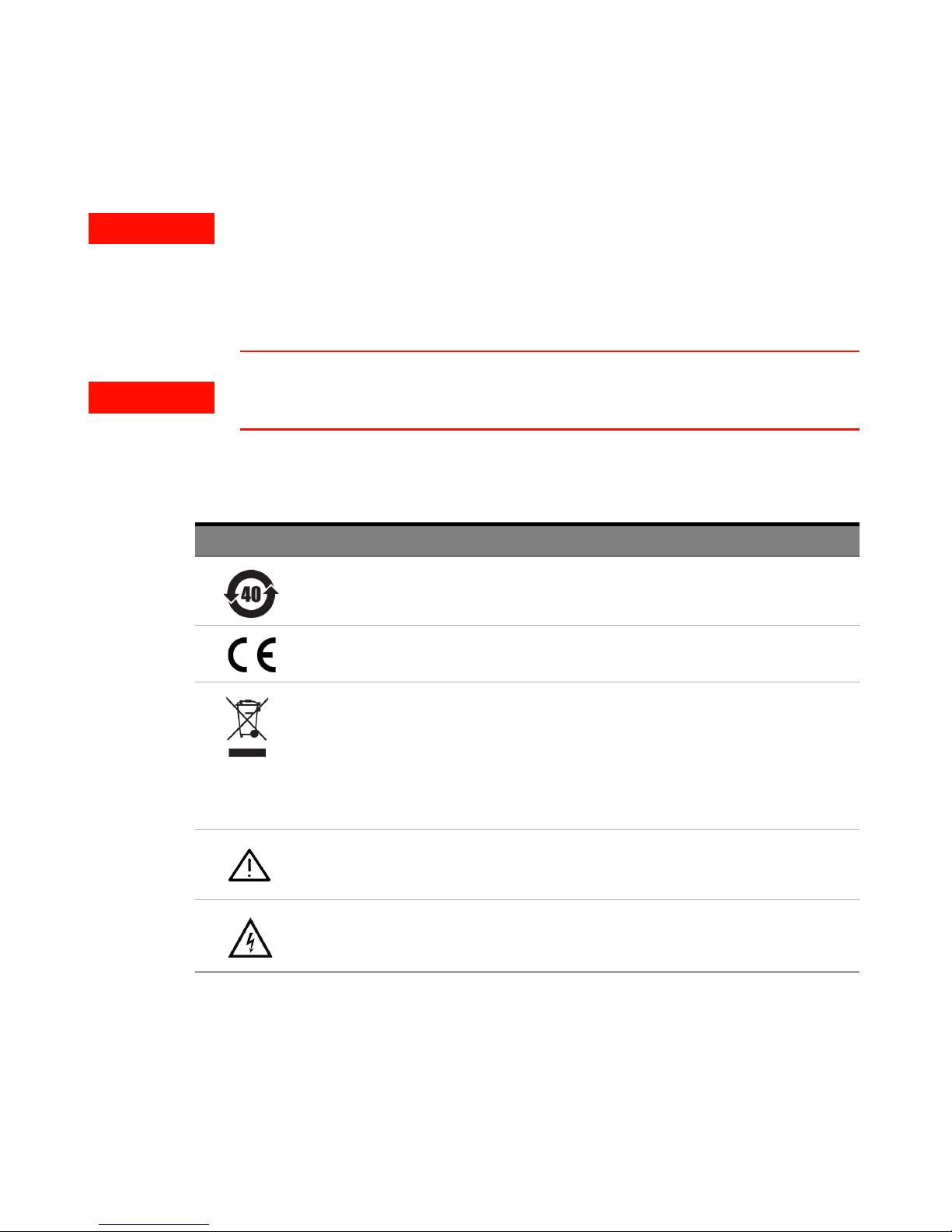
Instrument Markings and Symbols
Marking Description
This symbol indicates the Environmental Protection Use Period (EPUP) for the product’s
toxic substances for the China RoHS requirements.
Safety and Regulatory Information 4
The CE mark is a registered trademark of the European Community.
This product complies with the WEEE Directive (2002/96/EC) marking requirements. The
affixed label indicates that you must not discard this electrical/electronic product in
domestic household waste. Product Category: With reference to the equipment types in
the WEEE Directive Annex I, this product is classed as a “Monitoring and Control
instrumentation” product. Do not dispose in domestic household. To return unwanted
products, contact your local Keysight office, or refer to www.keysight.com for more
information.
The product is marked with this symbol when it is necessary for the user to refer to the
instructions in the documentation.
This symbol indicates a risk of electric shock. Refer to this manual for more information.
N7020A and N7024A Power Rail Probes User’s Guide 37
Page 38

4 Safety and Regulatory Information
38 N7020A and N7024A Power Rail Probes User’s Guide
Page 39
Keysight N7020A and N7024A Power Rail Probes
CAUTION
NOTE
User’s Guide
5 Using the Power Rail Probe
Requirements for Optimum Probe Performance 41
Low Source Impedance Required 41
Minimize Probe Ground Impedance for the Best Signal Fidelity 42
Connecting to the DUT 44
Replacing N7023A Probe Browser Tips 52
Avoiding Costly Repairs 53
Common Types of Power Integrity Measurements 55
This chapter describes requirements for ensuring optimum probe performance,
how to connect the probe to the DUT, and how to protect the oscilloscope and
probe from damage due to ESD.
Always wear an ESD wrist strap when working with active probes. Not doing so can result
in damage to the probe and to the oscilloscope’s input channel.
If the N7020A input is connected to an S-series oscilloscope at vertical settings at or below
20 mV/div with more than 200 mV of applied offset with no signal on the probe input, the
probe output may be indeterminate. Upon zeroing the offset, increasing the vertical setting, or
connecting the probe input to a low impedance (power rail), the output will be correctly
restored.
39
Page 40

5 Using the Power Rail Probe
NOTE
Connect the N7020A probe to a powered-on oscilloscope for at least 20 minutes before any
testing to allow the probe to warm up.
Connect the N7024A probe to an oscilloscope that has been powered-on for at least 20
minutes to allow the oscilloscope to warm up before any testing.
Ensure that the environmental conditions do not exceed the probe’s specified limits in
Chapter 3, “Specifications and Characteristics".
40 N7020A and N7024A Power Rail Probes User’s Guide
Page 41
Requirements for Optimum Probe Performance
Low Source Impedance Required
The N7020A and N7024A are designed explicitly for measuring DC power
supplies. In order to maintain a flat frequency response across the probe's
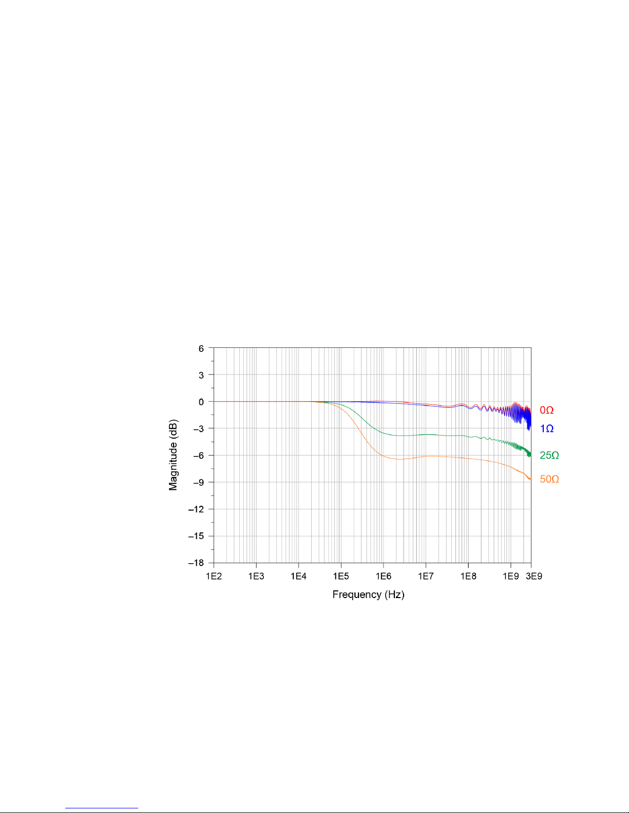
bandwidth, the DUT must have extremely low source impedance, like that of a
power rail. The probes have a non-flat input impedance that transitions from
50 kΩ at DC to 50Ω at 1 MHz and above. Therefore, if the DUT impedance is not
low, it will divide with the probe's impedance unequally across frequency, causing
a non-flat measurement. The recommended DUT impedance should be much less
than 1 ohm. At 1 ohm, the DC-to-AC non-flatness is about 2%. Figure 7 shows the
non-flatness for DUT impedances of 0Ω, 1Ω, 25Ω, and 50Ω.
Using the Power Rail Probe 5
Figure 7 Frequency Response (N7020A Probe with N7022A Main Cable) Versus DUT Im-
N7020A and N7024A Power Rail Probes User’s Guide 41
pedance
Page 42
5 Using the Power Rail Probe
To the DC component of a supply voltage, the probe presents a high impedance
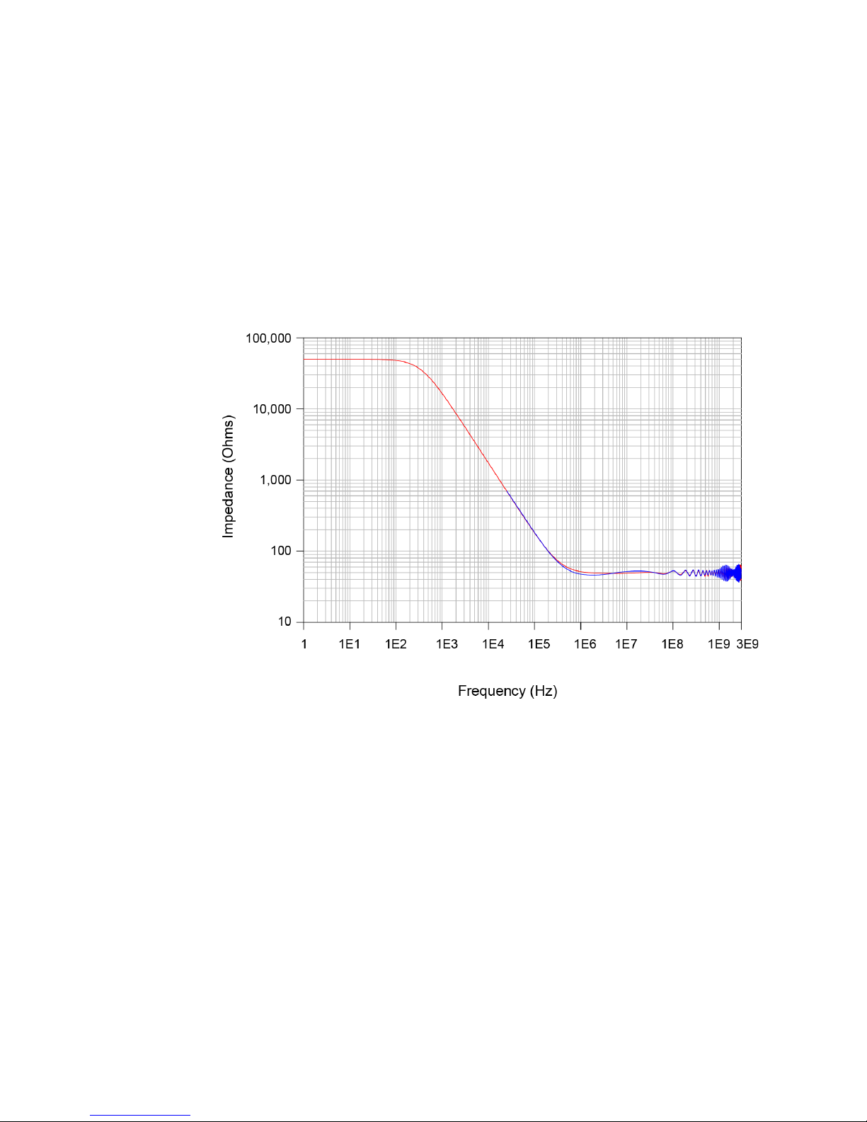
and thus low loading (about 50 kΩ). To the AC component of the supply voltage,
the probe presents a low 50Ω impedance. This probe’s low input impedance,
reduces noise on the probe’s output to the oscilloscope thus increasing
measurement range and accuracy.
The following graph shows the probe’s input impedance versus frequency.
Figure 8 Input Impedance Versus Frequency, Z
Minimize Probe Ground Impedance for the Best Signal Fidelity
The N7020A and N7024A probes are single-ended probes that are designed for
measuring small signals riding on large DC voltages. By using the oscilloscope’s
offset knob to offset the DC voltage, you can analyze a power rail using maximum
vertical sensitivity. With no added noise other than a 10% increase to the
oscilloscope channel's noise, due to low attenuation, these probes have very low
input noise. For example, at maximum sensitivity on an S-series oscilloscope, the
input-referred AC
42 N7020A and N7024A Power Rail Probes User’s Guide
(N7020A with N7022A Main Cable)
noise is 140 µV
rms
for N7020A.
rms
Measured, Zin Modeled
in
Page 43

Using the Power Rail Probe 5
To achieve the best signal fidelity, it is vital that the physical connection and
ground impedance of the probe be minimized. Any unnecessary length in either
the probe's signal or ground can potentially cause capacitive coupling and
inductive pick-up larger than the signal of interest. These probes support three
connection methods, well-suited for high fidelity measurements:
• The N7022A main cable, connected directly to an SMA port on the DUT,
provides the highest fidelity since the ground and signal are intimately mated
with an SMA connector. Connectors other than SMA such as SMB and SMC
can be used with an appropriate adapter. The adapters are not supplied with
the probe.
• The N7021A is a prepared coaxial-cable pigtail that allows the probe to be
soldered to the DUT. It is recommended that the coaxial shield be soldered
directly to ground, thus minimizing the ground impedance.
• The N7032A browser or N7033A browser with hand-held probing.
As with any single-ended probe, there may be a concern of creating a ground loop
by the connection of the DUT ground to the probe/scope ground. This generally
does not cause a measurement issue as long as the DUT ground is not radically
different than the scope ground. You can test this by connecting the probe’s
ground and signal contacts to the DUT ground. You should not see any significant
signal on the oscilloscope’s screen.
N7020A and N7024A Power Rail Probes User’s Guide 43
Page 44
5 Using the Power Rail Probe
NOTE
Connecting to the DUT
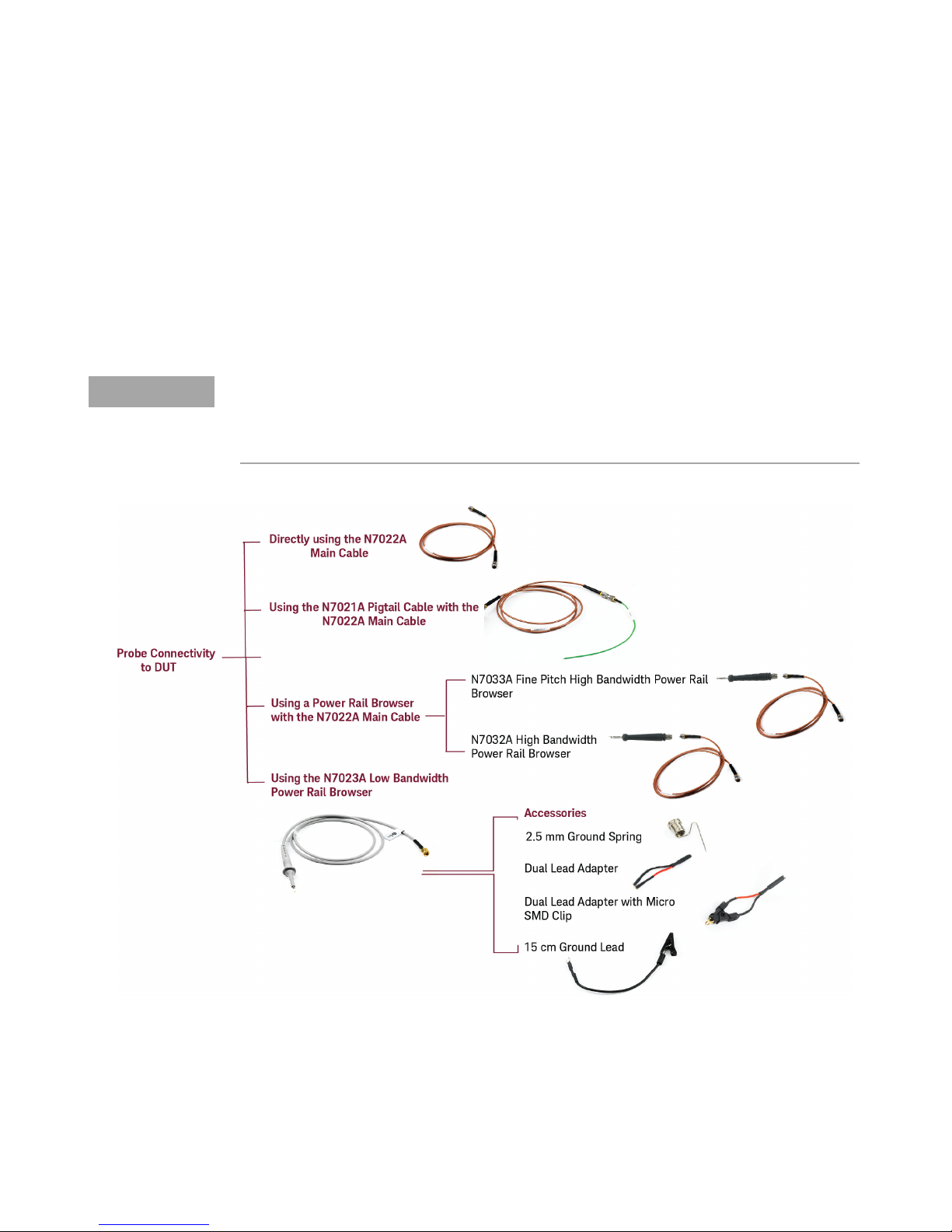
You can connect the N7020A / N7024A probe to the DUT in a number of ways
using various connection accessories shipped with these probes. The following
figure illustrates these connection methods and the correct combination of
accessories to be used for the most accurate measurements.
The compatible Keysight oscilloscopes include S-parameter correction for the
supplied N7021A and N7022A cables. Therefore, you should always use these
cables as per the combinations shown in the figure below for the most accurate
measurements.
These methods are described in the sections that follow.
44 N7020A and N7024A Power Rail Probes User’s Guide
Page 45
NOTE
Once you have made the hardware connection using the appropriate probe connection
accessory (cables/browsers), ensure that the same hardware connection mechanism is
reflected in the oscilloscope’s Infiniium software GUI. You do this using the Probe
Configuration dialog box. This ensures that you get accurate measurements as per the
connection mechanism.
For instance, if you are using the N7022A main cable with the N7024A probe, then ensure that
the Probe Configuration dialog box has N7022A:N7024A Main Cable as the selected head in
the Probe Head section.
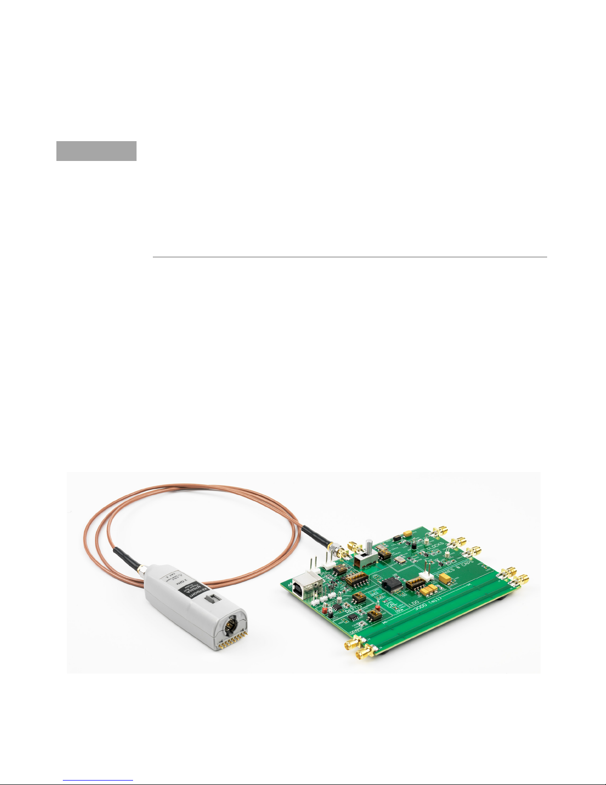
Direct Connection using the N7022A Main Cable
This connection mechanism allows you to directly probe DUTs that are located up
to 1.2 meters from the probe thereby ensuring an easy connection to the target.
The N7022A main cable is flexible and durable while still providing high signal
fidelity.
The highest BW configuration for the N7024A Voltage Rail probe system is when
the user has a 50 ohm line from a voltage rail on their DUT to an RF connector and
this is connected to the N7022A coax and N7024A probe amp combination.
Using the Power Rail Probe 5
You can achieve the highest bandwidth configuration for the N7024A probe by
connecting the N7022A main cable to an RF connector that connects to the DUT’s
power rail on a 50Ω line.
N7020A and N7024A Power Rail Probes User’s Guide 45
Page 46
5 Using the Power Rail Probe
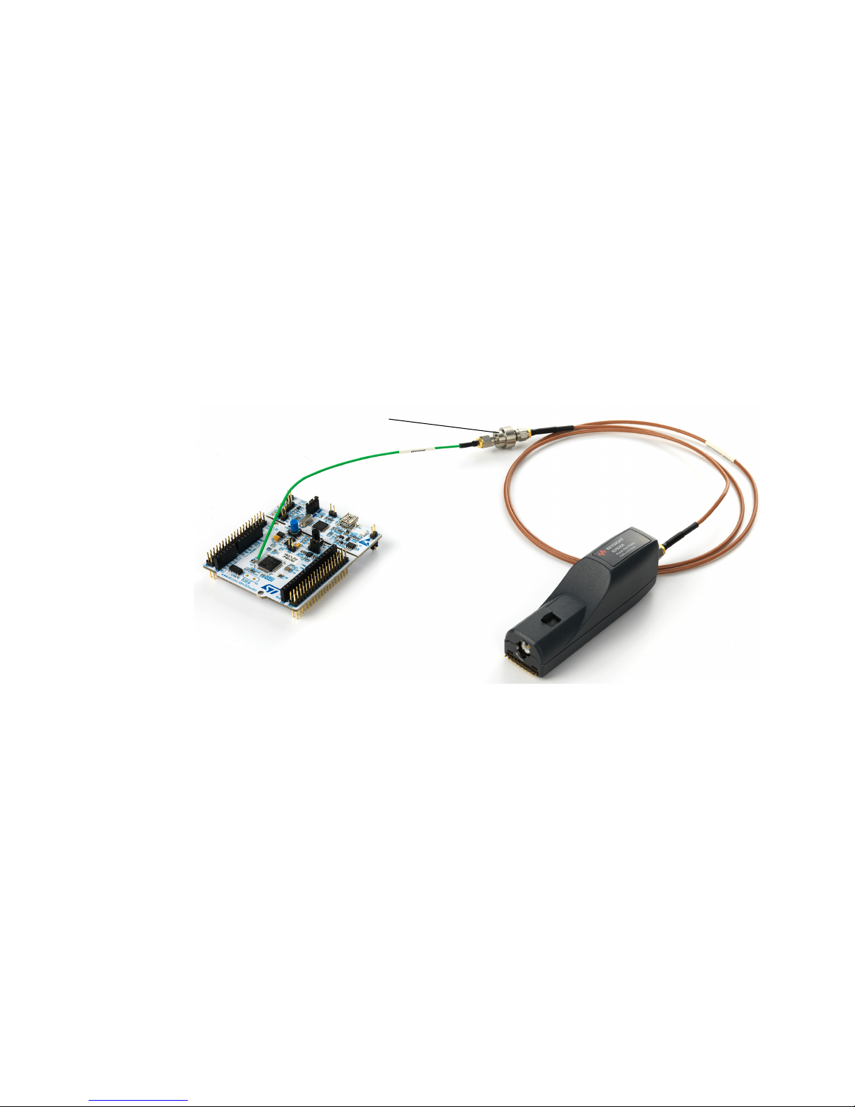
Rotating adapter used to
connect the cables
Using the N7021A Pigtail Cable and N7022A Main Cable
N7021A Pigtail cables are flexible and durable and have a small diameter to
minimize intrusions into target systems. The typical probing point will often be
across a bypass capacitor with the cable’s outside conductor soldered to ground.
1 Connect the probe to the N7022A main cable
2 Connect the main cable to the N7021A pigtail cable.
3 Use the supplied SMA adapter or Rotating adapter to connect the two cables.
4 Solder the pigtail cable to the DUT.
46 N7020A and N7024A Power Rail Probes User’s Guide
Page 47
Using the Power Rail Probe 5
CAUTION
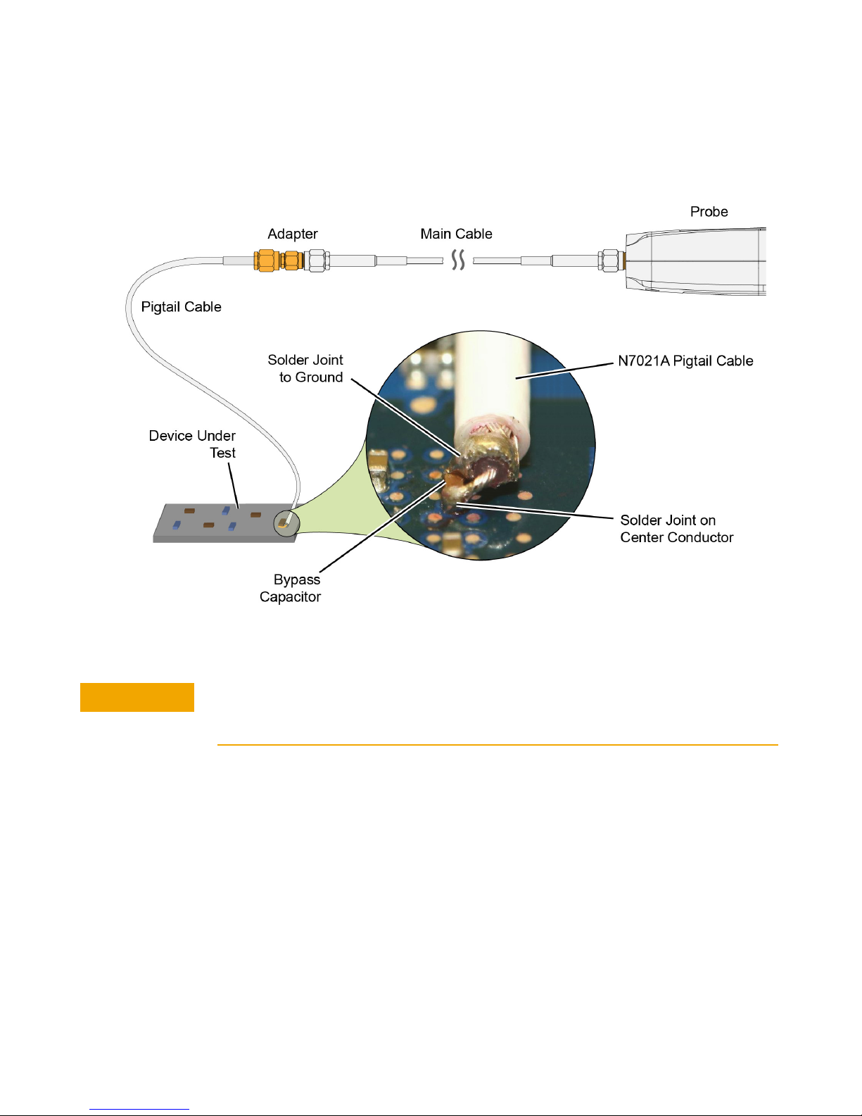
The figure below shows how to solder the end of a N7021A pigtail cable to a DUT.
Figure 9 Soldering the Probing End of The N7021A Cable Across a Bypass Capacitor
To avoid accidentally shorting the circuit via the cable’s exposed ground, place a small
strip of non-conductive tape onto the board before attaching the coax. To avoid undue
stress to the solder joints, tape the cable to the DUT.
N7020A and N7024A Power Rail Probes User’s Guide 47
Page 48
5 Using the Power Rail Probe
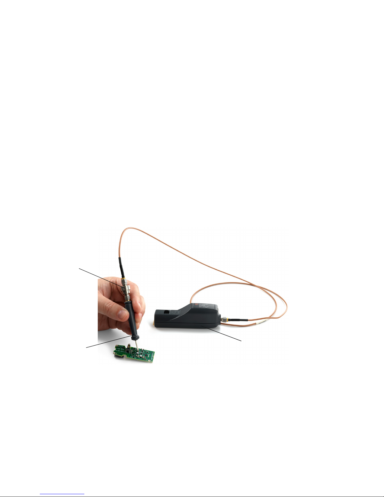
N7024A Probe
N7033A Browser
N7024A Probe
Rotating Adapter
Using a Power Rail Browser
The following browsers are available for use with the N7020A/N7024A probes.
Based on your bandwidth requirements, you can choose the browser that you
want to use. Refer to Chapter 3, “Specifications and Characteristics" to know the
capabilities of each of these browsers.
• N7023A Low Bandwidth Browser
• N7032A High Bandwidth Browser
• N7033A Fine Pitch High Bandwidth Browser
N7032A / N7033A Browser
Use the N7022A main cable to connect the probe to the N7032A / N7033A
browser. Use the supplied SMA adapter or Rotating adapter to make this
connection between the probe and browser.
Hands-free probing with N7032A / N7033A browser
For hands-free stability, you can mount these browsers on the N2787A probe
Positioner as displayed in the following figure.
48 N7020A and N7024A Power Rail Probes User’s Guide
Page 49
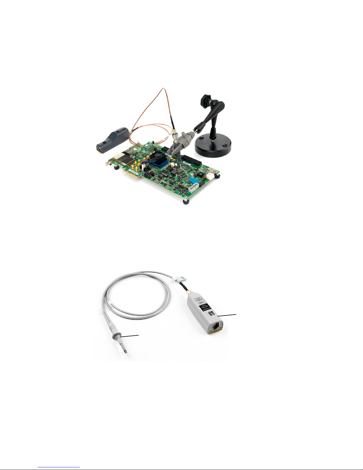
N7023A Browser
N7020A Probe
N7023A Browser
Using the Power Rail Probe 5
1 Remove the N7022A main cable (if attached to the probe)
2 Replace this cable with the N7023A browser cable to make the connection
between the probe and browser.
3 From the set of N7023A browser accessories, choose the accessory that best suits
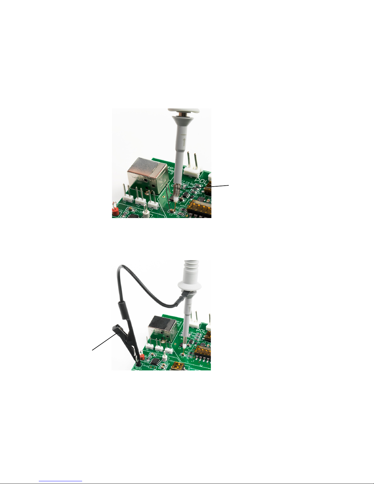
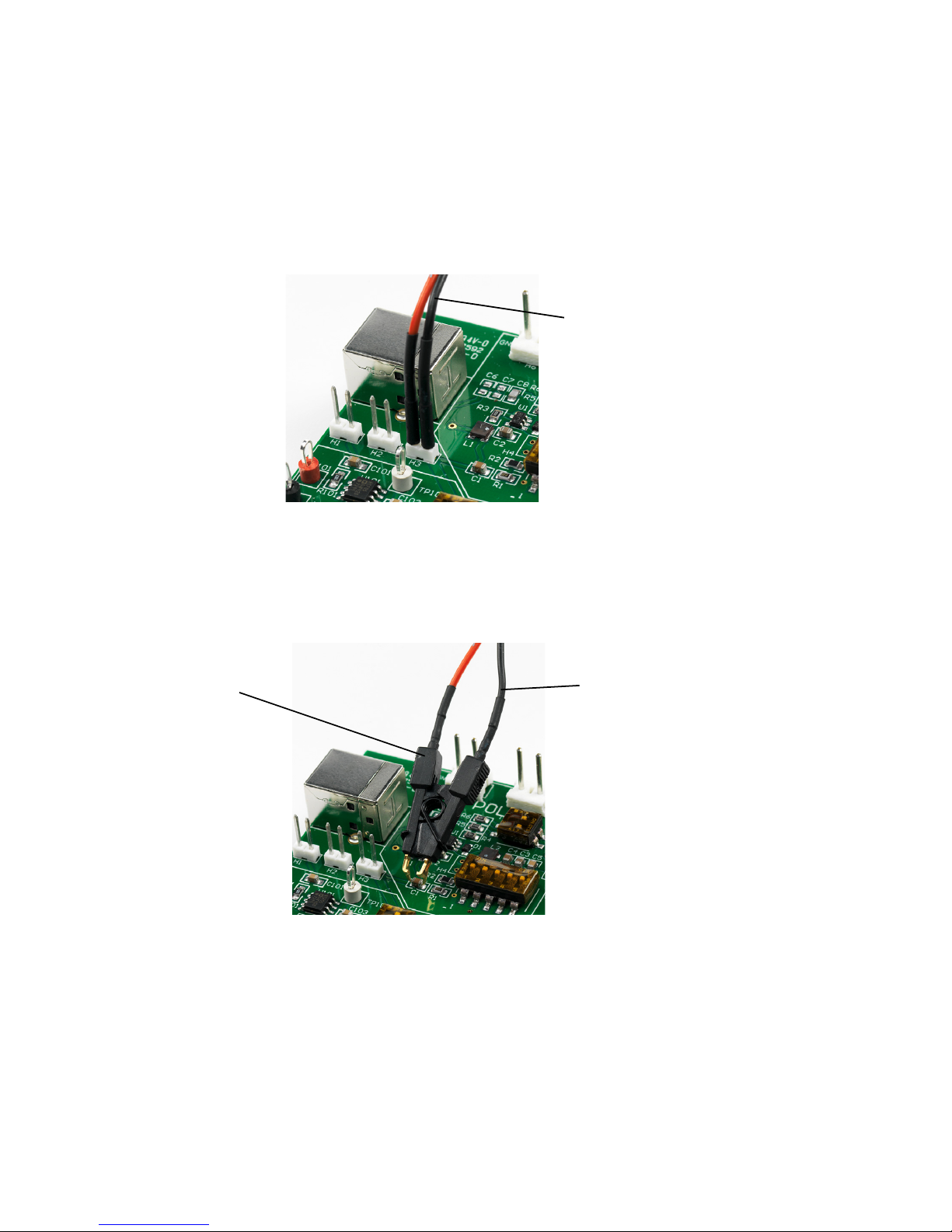
your requirement as per the probing point on the DUT. Connect this accessory to
the browser tip as displayed in the figures below.
N7020A and N7024A Power Rail Probes User’s Guide 49
Page 50
5 Using the Power Rail Probe
Ground Spring
Ground Lead
• Use the Ground Spring to get the highest performance connection for the
N7023A browser. Its flexible construction makes it easy to vary the span
between the input and ground to accommodate the device being probed.
• Use the Ground Lead to reach grounding locations that are farther away from
the probing location than can be reached by the ground spring. However,
the longer lead means it has a larger inductance in the ground return path
which corresponds to a lower performance than using the ground spring.
50 N7020A and N7024A Power Rail Probes User’s Guide
Page 51
Using the Power Rail Probe 5
Dual Lead
Adapter
Micro SMD Clip
Dual Lead
Adapter
• Use the Dual Lead Adapter to easily connect the N7023A browser to popular
0.1” pin headers with 0.025” square pins. This dual lead adapter has no
shorting hazards since all external metal surfaces are insulated.
• Use the Micro SMD clips in conjunction with the dual lead adapter for fast and
convenient hands-free probing of surface mount capacitors. It is a best
practice to twist the leads of the dual lead adapter to reduce coupling of
external noise into the probe.
N7020A and N7024A Power Rail Probes User’s Guide 51
Page 52
5 Using the Power Rail Probe
WARNING
Replacing N7023A Probe Browser Tips
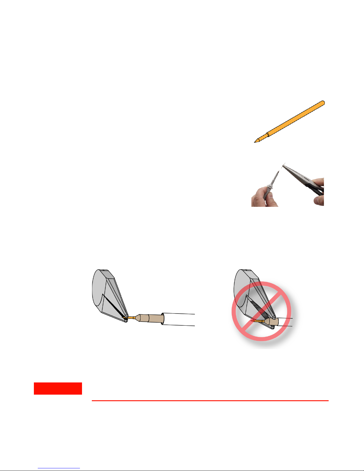
The solid tips and spring-loaded tips are replaceable.
Spring loaded power rail probe browser tips offer a
method of probing signals that is less susceptible to
vibration or movement than traditional rigid tips.
Many users find it easier to use this type of tip. The
spring loaded tips work when they are either partially
or fully compressed and are protected against over compression damage.
To change the N7023A power rail probe browser tip,
use pliers to grip the tip and pull it straight out of its
contact socket along the axis of the N7023A power
rail probe browser. Do not grip the plastic insulator or
the housing with the pliers because the tip could be
crushed (see Figure 10). This could result in being
unable to remove the tip and/or damaging the
N7023A power rail probe browser. Once the N7023A power rail probe browser tip
is removed, the new tip can be inserted with pliers into the contact socket along
the axis of the N7023A power rail probe browser. In order to insert the N7023A
power rail probe browser tip completely into the housing, carefully press the
browser tip against a hard surface.
Figure 10 Proper Tip Removal Technique
You should exercise caution when using these sharp browser tips to avoid personal
injury.
52 N7020A and N7024A Power Rail Probes User’s Guide
Page 53
Avoiding Costly Repairs
CAUTION
WARNING
When connecting or using the probe, use caution to avoid damaging the
oscilloscope’s channel input circuits due to electrostatic discharge (ESD).
When the probe is connected to the oscilloscope, the
oscilloscope’s channel input circuits can be damaged by
electrostatic discharge (ESD). Avoid applying static
discharges to the probe input. Prior to energizing and
connecting any accessory cable to the probe,
momentarily short the center and outer conductors of
the cable together. Be sure that the instrument is
properly earth-grounded to prevent buildup of static
charge. Wear a wrist-strap or heel-strap.
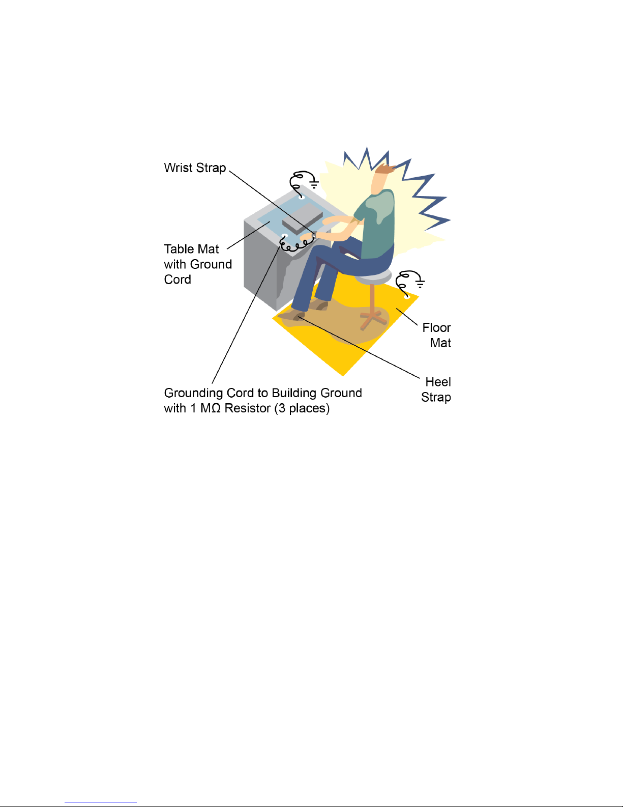
Figure 11 on page 54 shows an example of a static-safe work station using two
types of ESD protection:
Using the Power Rail Probe 5
• Conductive table-mat and wrist-strap combination.
• Conductive floor-mat and heel-strap combination.
Both types, when used together, provide a significant level of ESD protection. Of
the two, only the table-mat and wrist-strap combination provides adequate ESD
protection when used alone. To ensure user safety, the static-safe accessories
must provide at least 1 MΩ of isolation from ground. Purchase acceptable ESD
accessories from your local supplier.
These techniques for a static-safe work station should not be used when working on
circuitry with a voltage potential greater than 500 volts.
N7020A and N7024A Power Rail Probes User’s Guide 53
Page 54
5 Using the Power Rail Probe
Figure 11 ESD Workstation
54 N7020A and N7024A Power Rail Probes User’s Guide
Page 55
Common Types of Power Integrity Measurements
The following are some of the common types of power integrity measurements
that you can make using the N7020A / N7024A probe:
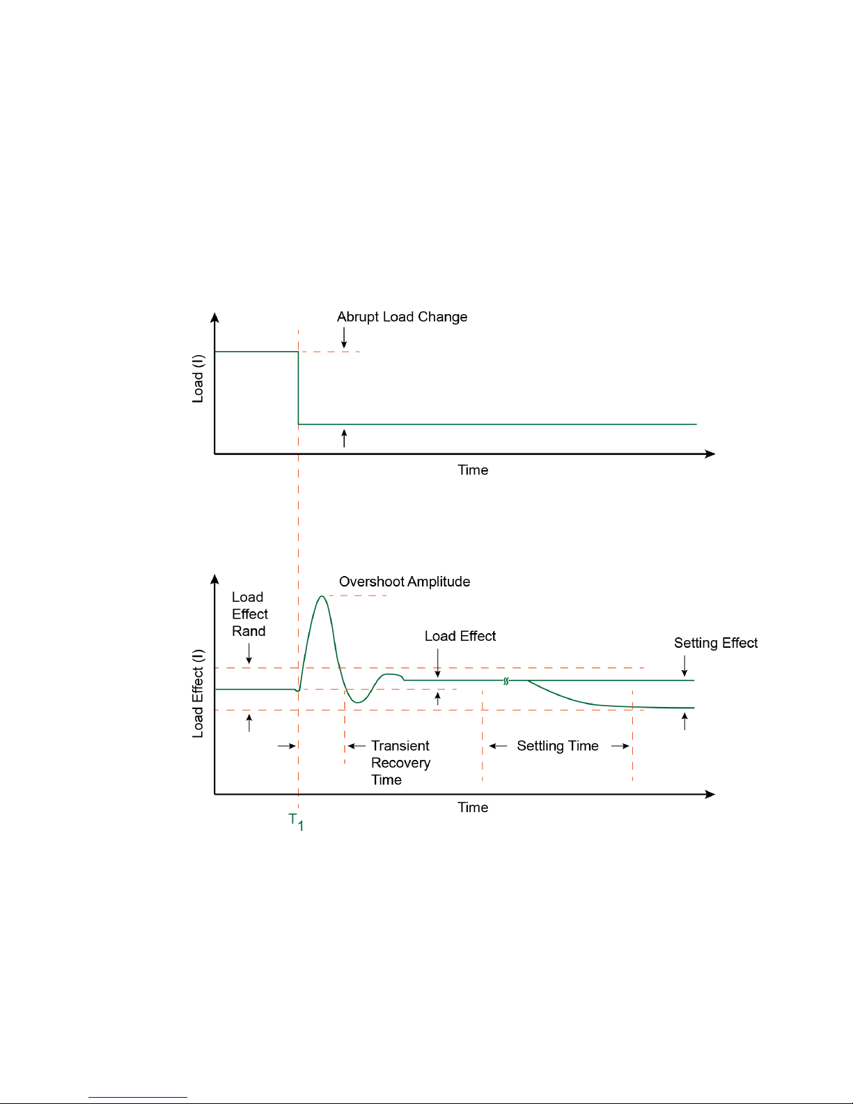
• Static and dynamic load response.
Using the Power Rail Probe 5
Figure 12 Example of Response to Changing Load
• Supply drift.
• Programmable power rail response.
N7020A and N7024A Power Rail Probes User’s Guide 55
Page 56
5 Using the Power Rail Probe
• High frequency transients and noise.
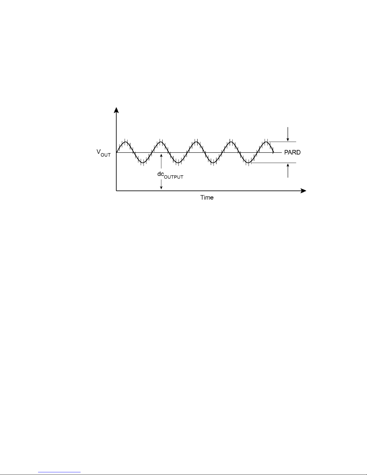
• PARD (Periodic and Random Disturbances) such as noise, ripple, and switching
transients on power rails.
Figure 13 Example of PARD on DC Output
• Product electrical validation at extended temperatures.
56 N7020A and N7024A Power Rail Probes User’s Guide
Page 57

Keysight N7020A and N7024A Power Rail Probes
CAUTION
User’s Guide
6 Calibrating
N7020A / N7024A Probe’s DC Attenuation/Offset Calibration Using N7022A Main Cable 58
N7020A / N7024A Probe’s DC Attenuation/Offset Calibration Using N7023A Probe
Browser 59
Always calibrate the probe before making any critical measurements. A probe
calibration removes attenuation errors, offset errors, and timing delays that are
introduced by the probe. This chapter contains basic calibration procedures for
the supported Infiniium oscilloscopes. For additional information on the probe
calibration, refer to the oscilloscope’s user documentation.
Always wear an ESD wrist strap when working with active probes. Not doing so can result
in the probe becoming permanently damaged.
The following calibrations are described in this chapter:
• N7020A / N7024A Probe’s DC Attenuation/Offset Calibration Using N7022A
Main Cable
• N7020A / N7024A Probe’s DC Attenuation/Offset Calibration Using N7023A
Power Rail Probe Browser
57
Page 58
6 Calibrating
N7020A / N7024A Probe’s DC Attenuation/Offset Calibration Using
N7022A Main Cable
1 Turn on the oscilloscope and connect the N7020A / N7024A probe with the
N7022A main cable attached to one of the oscilloscope’s input channels.
2 Allow the oscilloscope to warm up for 20 minutes.
3 If the oscilloscope needs calibration, perform a user calibration before the probe
calibration. On the oscilloscope, click Utilities > Calibration.
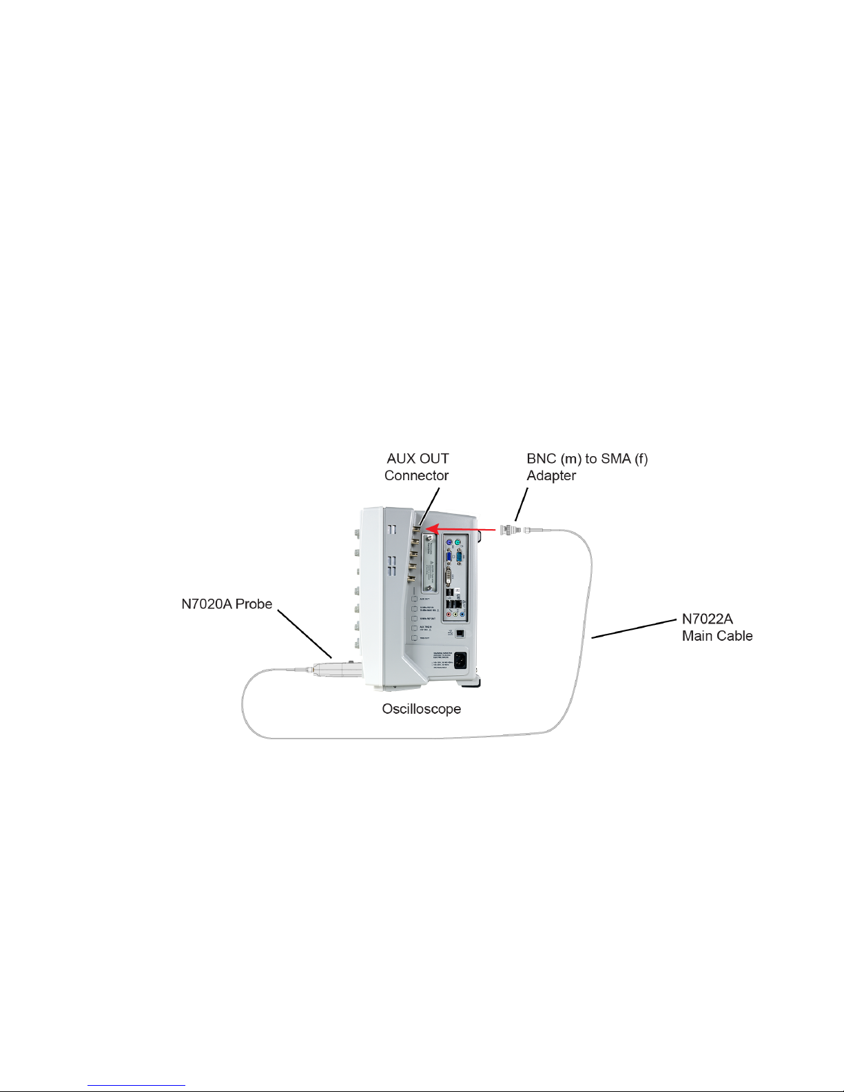
4 Connect the output of the N7022A main cable to the oscilloscope’s rear-panel
AUX OUT BNC connector as shown in the following picture. You’ll need a BNC (m)
to SMA (f) adapter.
Figure 14 Calibration Setup
5 On the oscilloscope, click Setup > Probes.
6 In the Probe Calibration dialog box, select the tab representing the channel that
has the probe attached.
7 In the dialog box, select the type of calibration. Click Start and follow the
instructions shown on the oscilloscope.
58 N7020A and N7024A Power Rail Probes User’s Guide
Page 59

Calibrating 6
N7020A / N7024A Probe’s DC Attenuation/Offset Calibration Using
N7023A Probe Browser
1 Turn on the oscilloscope and connect the N7023A power rail probe browser with
the N7020A / N7024A probe attached to one of the oscilloscope’s input channels.
2 Allow the oscilloscope to warm up for 20 minutes.
3 If the oscilloscope needs calibration, perform a user calibration before the probe
calibration. On the oscilloscope, click Utilities > Calibration.
4 Connect the ground lugs and the output of the N7023A power rail probe browser
to the oscilloscope’s front-panel PROBE COMP connector.
5 On the oscilloscope, click Setup > Probes.
6 In the Probe Calibration dialog box, select the tab representing the channel that
has the probe attached.
7 In the dialog box, select the type of calibration. Click Start and follow the
instructions shown on the oscilloscope.
N7020A and N7024A Power Rail Probes User’s Guide 59
Page 60

6 Calibrating
60 N7020A and N7024A Power Rail Probes User’s Guide
Page 61

Keysight N7020A and N7024A Power Rail Probes
User’s Guide
7 Performance Plots
N7020A Performance Plots 62
N7020A Input Impedance Equivalent Model 66
N7024A Performance Plots 68
N7024A Input Impedance Plots 70
This chapter includes plots that show the characteristic performance and an input
impedance model of the N7020A and N7024A probes.
61
Page 62
7 Performance Plots
N7020A Performance Plots
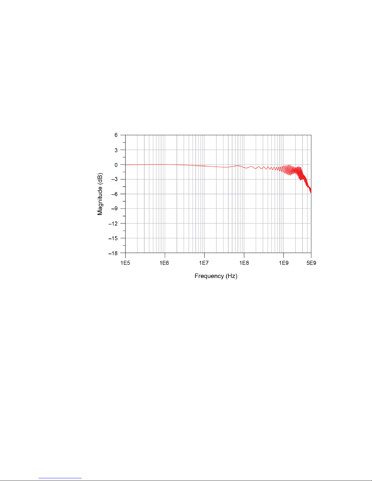
The performance characteristic plots in this section are for the N7020A probe with
the N7022A main cable attached.
Figure 15 Normalized Frequency Response, V
62 N7020A and N7024A Power Rail Probes User’s Guide
(N7020A with N7022A Main Cable)
out/Vin
, 2.5 GHz BW
Page 63

Performance Plots 7
Figure 16 Frequency Response for Different DUT Impedances
(N7020A with N7022A Main Cable)
N7020A and N7024A Power Rail Probes User’s Guide 63
Page 64
7 Performance Plots
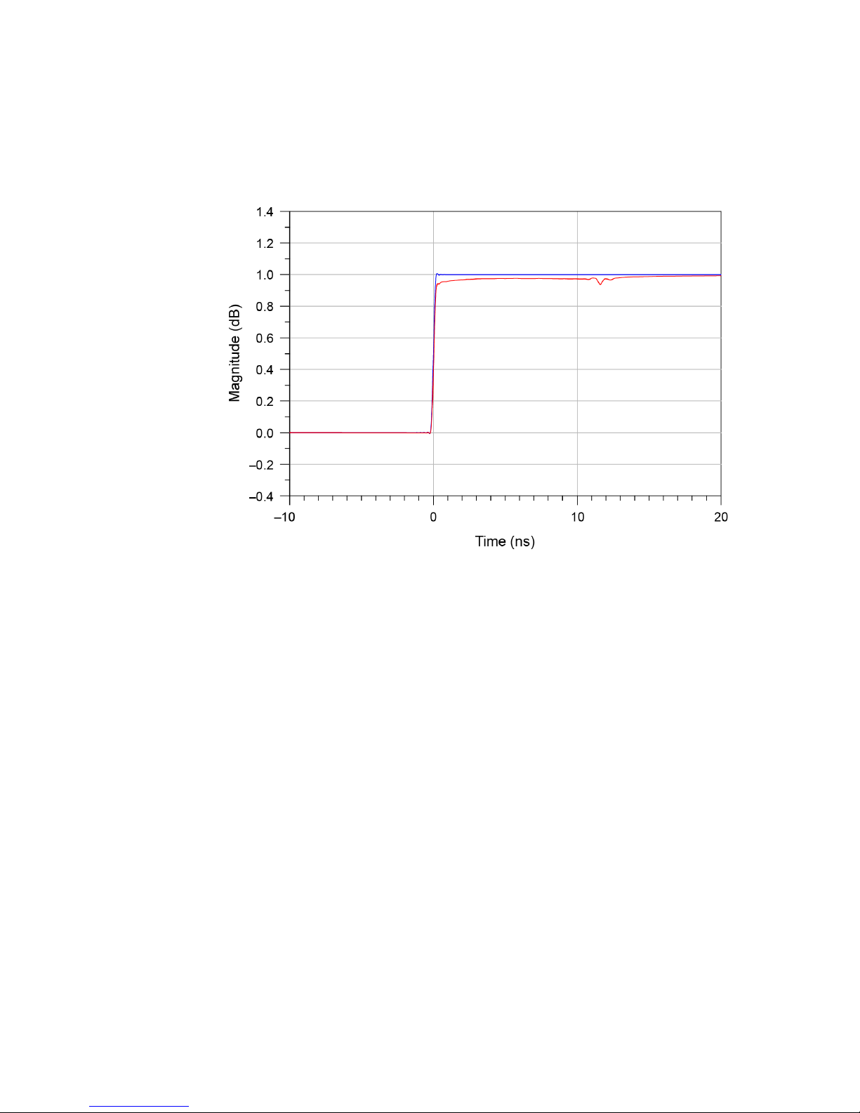
Rise Time, Input Step (10/90%): . . . . . . . . . . . . . . . . . . . . . . . . . . . . . . . . . 250 ps
Rise Time, Input Step (20/80%): . . . . . . . . . . . . . . . . . . . . . . . . . . . . . . . . . 169 ps
Rise Time, N7020A with N7022A (10/90%): . . . . . . . . . . . . . . . . . . . . . . . . 297 ps
Rise Time, N7020A with N7022A (20/80%): . . . . . . . . . . . . . . . . . . . . . . . . 192 ps
Figure 17 Step Tracking (N7020A with N7022A Main Cable)
64 N7020A and N7024A Power Rail Probes User’s Guide
Page 65
Performance Plots 7
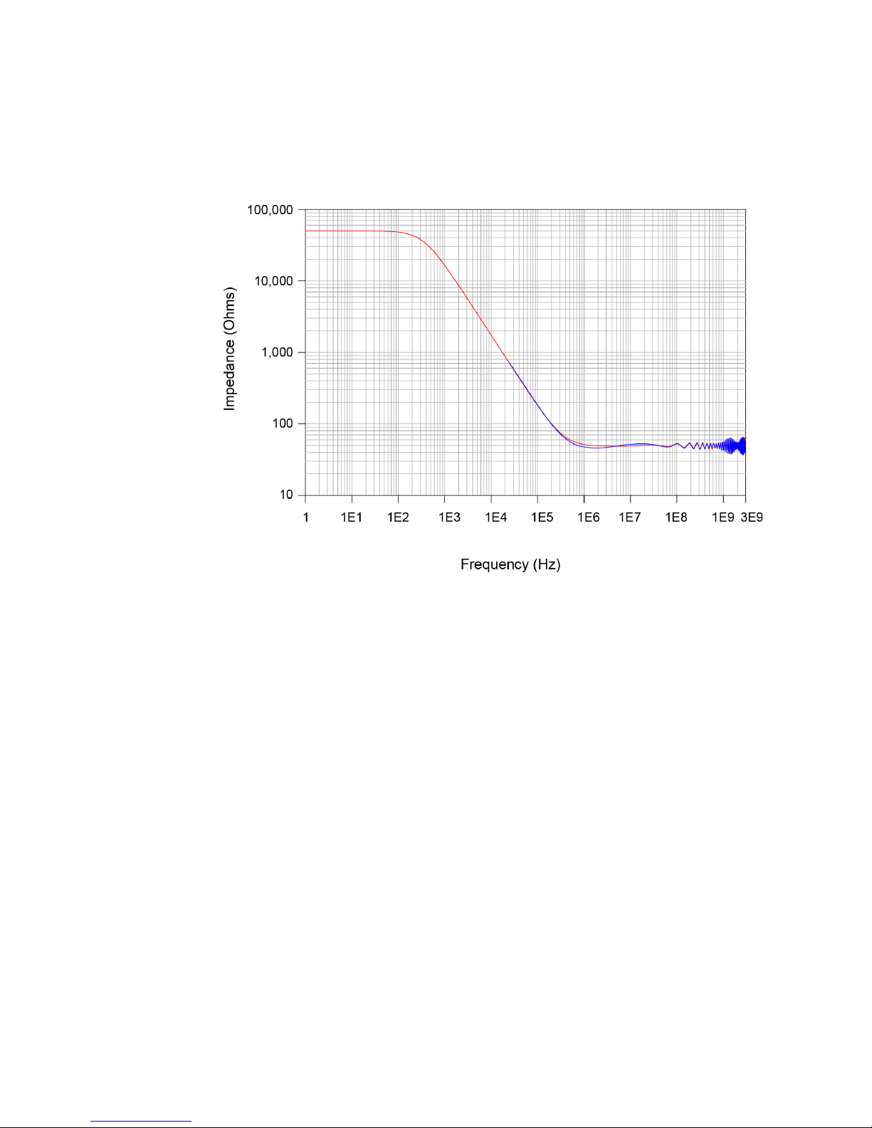
Figure 18 Input Impedance Versus Frequency, Z
(N7020A with N7022A Main Cable)
Measured, Zin Modeled
in
N7020A and N7024A Power Rail Probes User’s Guide 65
Page 66

7 Performance Plots
N7020A Input Impedance Equivalent Model
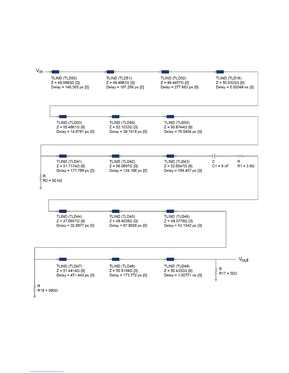
The following Netlist is for the N7020A input impedance equivalent model shown
in Figure 19 on page 67.
* source N7020A
.EXTERNAL INPUT Vin
.EXTERNAL OUTPUT Vout
R_R3 GND N01679 590
T_T8 N01635 GND N01646 GND Z0=51.7174 TD=177.789ps
T_T4 N01611 GND N01614 GND Z0=50.0323 TD=5.00049ns
T_T9 N01646 GND N01649 GND Z0=56.0807 TD=124.106ps
T_T10 N01649 GND N01652 GND Z0=52.0547 TD=194.457ps
T_T5 N01614 GND N01629 GND Z0=55.4861 TD=14.8781ps
T_T16 N01709 GND VOUT GND Z0=50.4332 TD=1.00771ns
T_T15 N01706 GND N01709 GND Z0=50.9109 TD=173.772ps
C_C1 N01652 N01667 9n
R_R2 N01667 N01670 3.9
T_T11 N01670 GND N01673 GND Z0=47.0657 TD=32.9877ps
T_T12 N01673 GND N01676 GND Z0=48.4028 TD=97.8628ps
T_T14 N01679 GND N01706 GND Z0=51.4414 TD=471.443ps
T_T6 N01629 GND N01632 GND Z0=52.1033 TD=38.7418ps
T_T13 N01676 GND N01679 GND Z0=48.0776 TD=53.1542ps
T_T1 Vin GND N01605 GND Z0=49.0683 TD=148.305ps
R_R4 GND VOUT 50
T_T2 N01605 GND N01608 GND Z0=49.4981 TD=107.256ps
T_T7 N01632 GND N01635 GND Z0=50.8744 TD=76.0454ps
T_T3 N01608 GND N01611 GND Z0=49.4457 TD=277.663ps
R_R1 GND N01635 50k
66 N7020A and N7024A Power Rail Probes User’s Guide
Page 67
Performance Plots 7
Figure 19 Input Impedance Equivalent Model
N7020A and N7024A Power Rail Probes User’s Guide 67
Page 68

7 Performance Plots
N7024A Performance Plots
N7024A Probe System Responses
Most high performance active probes for use with Infiniium real-time oscilloscopes
utilize DSP correction filters to enhance the measurements accuracy. Probes like
the N7024A store their unique s parameters in on-board memory for the scope to
readout when needed. Probe heads are simple passive devices and, with careful
manufacture, their s-parameters don't vary significantly so they are stored as
nominal s-parameters in the oscilloscope. When a probe is connected to an
oscilloscope channel and the proper probe head is selected, the oscilloscope
calculates a DSP correction filter that includes the probe head, probe amplifier,
and oscilloscope channel. This provides the maximum measurement accuracy for
the complete probe and scope channel system. Since there are different probe
amplifiers and probe head combinations, it is not reasonable to show the
responses of all these combinations and the responses would all be very much the
same because they are all corrected to same target system response. The target
system response is a flat magnitude, flat phase response high order low-pass filter
that maximizes measurement accuracy.
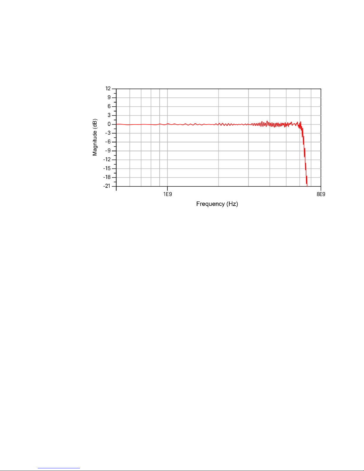
Figure 20 shows an example of a typical corrected system frequency response of
the N7024A probe when used with the N7022A main cable. This is the V
response which is indicative of the response seen when probing a very low
impedance voltage rail.
out/Vin
68 N7020A and N7024A Power Rail Probes User’s Guide
Page 69
Performance Plots 7
Figure 20 Typical Corrected Frequency Response for the N7022A Main Cable and N7024A
Probe Combination
N7020A and N7024A Power Rail Probes User’s Guide 69
Page 70
7 Performance Plots
N7024A Input Impedance Plots
This section provides the input impedance plots for various probe configurations
available for N7024A based on the different probe and probe head combinations.
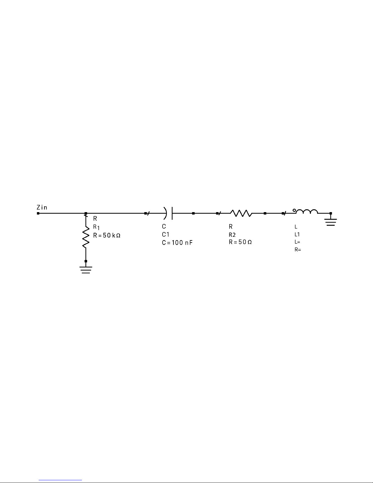
N7024A Simplified Input Impedance Model
Figure 21 shows the model used in the measured and modeled input impedance
plots provided for the N7024A probe in this section.
In this model, the value of the inductance L varies for various supported probe
configurations. This value is provided with the input impedance plot of each of
these probe configurations in this section.
Figure 21 Input Impedance Model for the N7024A Probe
Input Impedance Plot for N7022A Main Cable and N7024A Probe
Combination
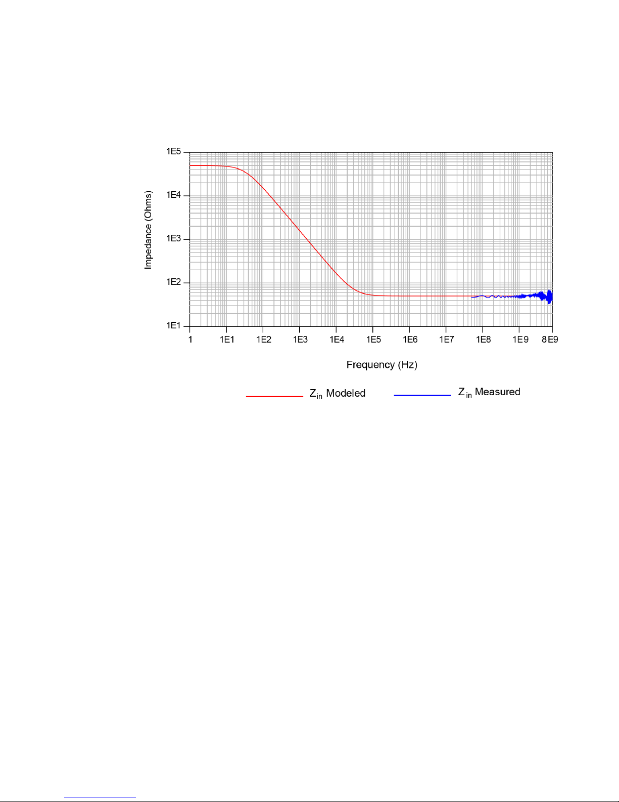
This combination supports the highest bandwidth configuration for the N7024A
probe. In this combination, the value of the inductance L is zero.
Figure 22 shows the input impedance looking into the N7022A cable. Any added
transmission line and/or connection parasitic on the DUT will modify this
impedance.
70 N7020A and N7024A Power Rail Probes User’s Guide
Page 71
Performance Plots 7
Figure 22 Input Impedances (Z
and N7024A Probe Combination
Modeled and Zin Measured) for the N7022A Main Cable
in
N7020A and N7024A Power Rail Probes User’s Guide 71
Page 72
7 Performance Plots
Input Return Loss Plot for N7022A Main Cable and N7024A Probe
Combination
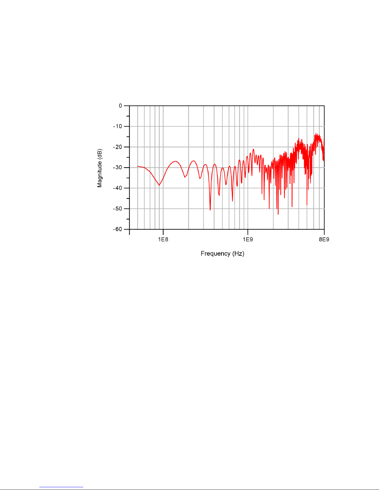
Figure 23 Input Return Loss Plot for the N7022A Main Cable and N7024A Probe Combina-
tion
72 N7020A and N7024A Power Rail Probes User’s Guide
Page 73
Performance Plots 7
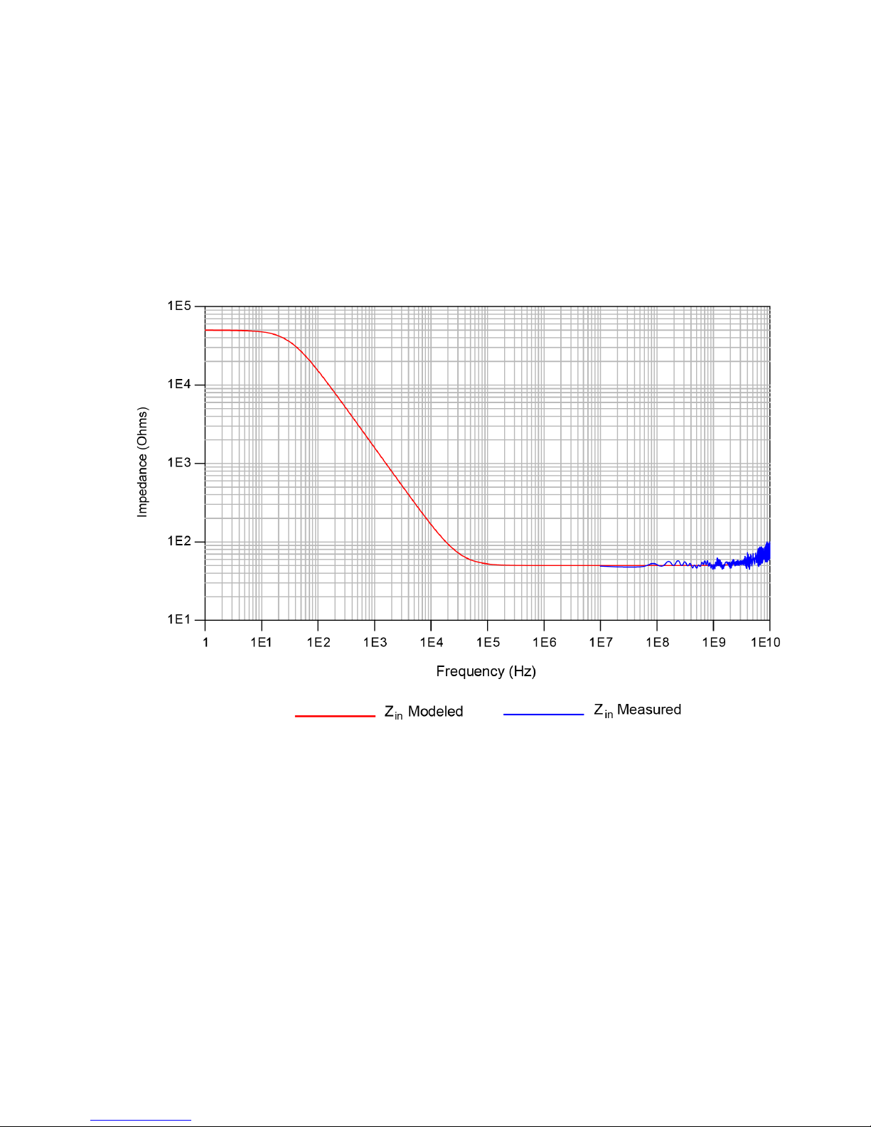
Input Impedance Plot for N7021A Pigtail Cable, N7022A Main Cable,
and N7024A Probe Combination
In this combination, the value of the inductance L is 1nH.
Figure 24 Input Impedances (Z
N7020A and N7024A Power Rail Probes User’s Guide 73
Modeled and Zin Measured) for the N7021A Pigtail Cable,
in
N7022A Main Cable, and N7024A Probe Combination
Page 74
7 Performance Plots
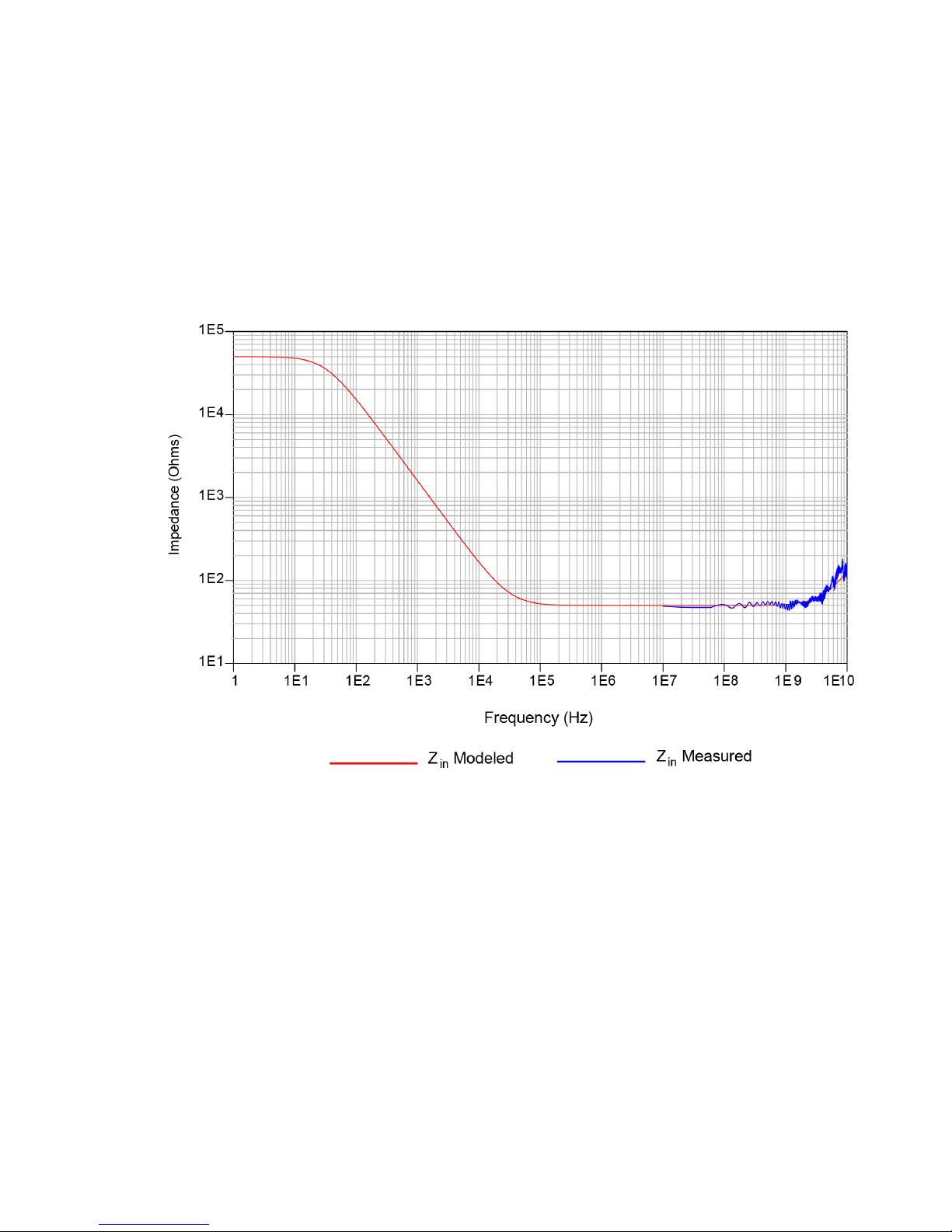
Input Impedance Plot for N7032A Browser, N7022A Main Cable, and
N7024A Probe Combination
In this combination, the value of the inductance L is 1.85 nH.
Figure 25 Input Impedances (Z
74 N7020A and N7024A Power Rail Probes User’s Guide
Modeled and Zin Measured) for the N7032A Browser,
in
N7022A Main Cable, and N7024A Probe Combination
Page 75
Performance Plots 7
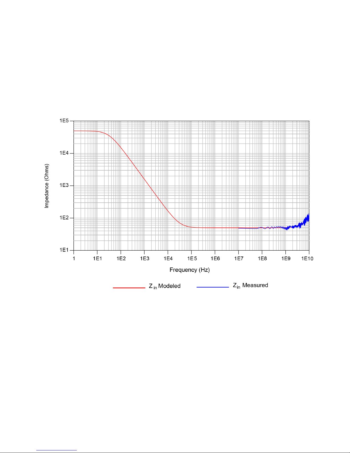
Input Impedance Plot for N7033A Browser, N7022A Main Cable, and
N7024A Probe Combination
In this combination, the value of the inductance L is 1.5 nH.
Figure 26 Input Impedances (Z
N7020A and N7024A Power Rail Probes User’s Guide 75
Modeled and Zin Measured) for the N7033A Browser,
in
N7022A Main Cable, and N7024A Probe Combination
Page 76

7 Performance Plots
76 N7020A and N7024A Power Rail Probes User’s Guide
Page 77

Keysight N7020A and N7024A Power Rail Probes
CAUTION
User’s Guide
8 Performance Verification
DC Input Resistance Performance Verification 78
Bandwidth Performance Verification for N7024A Probe 81
Electrostatic discharge (ESD) can quickly and imperceptibly damage or destroy high
performance probes, resulting in costly repairs. Always wear a wrist strap when handling
probe components and ensure that cables are discharged before being connected.
77
Page 78
8 Performance Verification
NOTE
DC Input Resistance Performance Verification
This section provides information to test that the N7020A / N7024A probe meets
its warranted DC input resistance, which is 50 kΩ±2%.
Allow the N7020A probe to warm up for at least 20 minutes.
Table 13 Required Test Equipment
Test Equipment Critical Specification Keysight Model Number
Oscilloscope Supported Oscilloscope Refer to the topic “Oscilloscope
Compatibility" on page 16 to get a list of
supported oscilloscopes.
Digital Multimeter 2 wire resistance accuracy > ± 0.01% 34401A or equivalent
Adapter BNC (f) to SMA (m) (In E2655C Kit) E2655-83201
Procedure
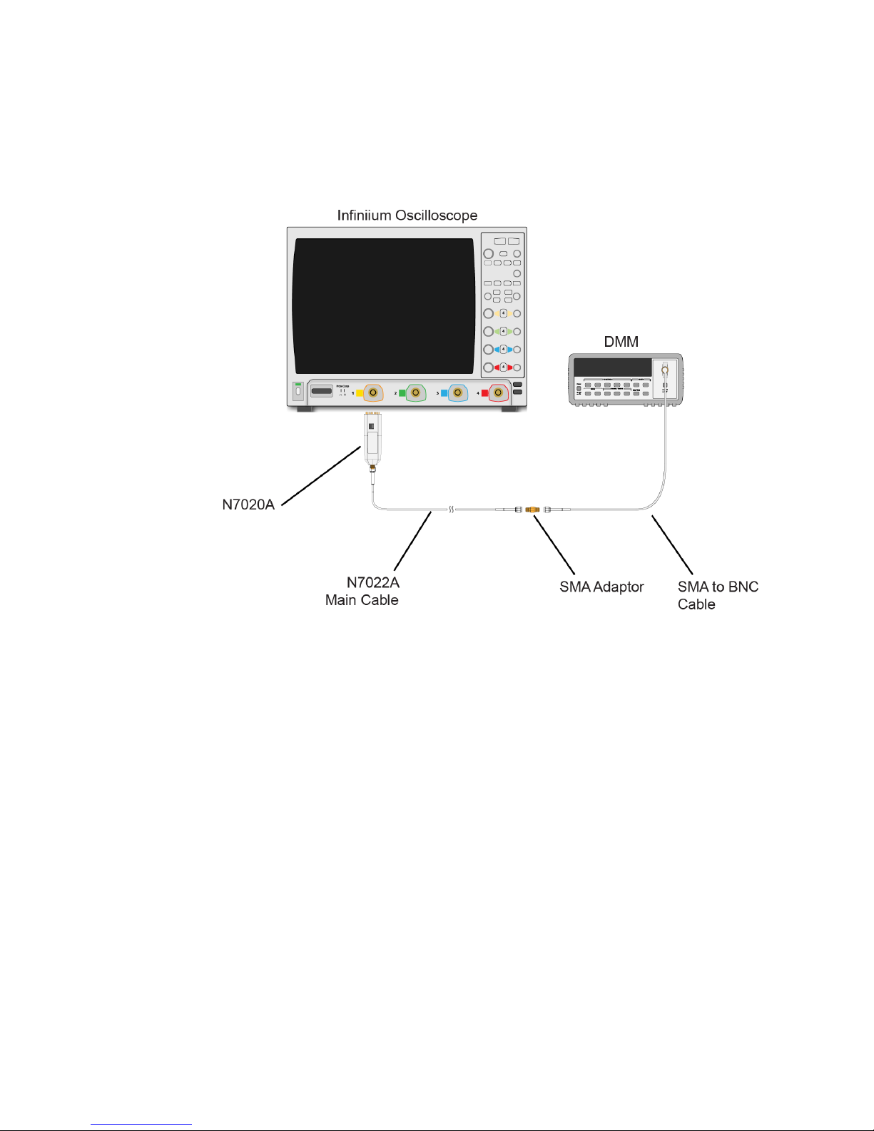
1 Connect the equipment as shown in Figure 27.
2 Power on the oscilloscope with the oscilloscope application maximized.
3 Power on the DMM and select the 2-wire Ohm display on the DMM.
78 N7020A and N7024A Power Rail Probes User’s Guide
Page 79
Performance Verification 8
Figure 27 Test Setup
4 Read the DMM display for the input resistance.
5 Record the result in Table 14 on page 80. To pass this test the result should be
between 49 kΩ and 51 kΩ.
Performance Test Record
Serial #:
Date:
Tested by:
Recommended Next Test Date:
N7020A and N7024A Power Rail Probes User’s Guide 79
Page 80
8 Performance Verification
Table 14 Input Impedance Test Results
Test Limits Result Pass/Fail
50 kΩ ± 2%
80 N7020A and N7024A Power Rail Probes User’s Guide
Page 81
Performance Verification 8
NOTE
Bandwidth Performance Verification for N7024A Probe
This section provides information to test that the N7024A probe meets its
warranted bandwidth specification, which is 6 GHz. As the warranted specification
is just for the N7024A probe, this performance verification procedure verifies the
bandwidth of just the N7024A probe without its N7022A main cable.
Table 15 Required Test Equipment
Test Equipment Critical Specification Keysight Model Number
Infiniium Oscilloscope Supported oscilloscope with bandwidth >= 8
GHz
Precision BNC Adapter If V or Z-series Infiniium oscilloscope (with
AutoProbe 2 inputs) is being used
Precision BNC (M) to SMA (F) Adapter If S-series Infiniium oscilloscope (with
AutoProbe 1 inputs) is being used
Calibration Coaxial Cable The calibration cable that accompanies the
oscilloscope
or
A high quality 3.5mm or 2.92mm coax cable
Adapters to connect the coax cable to Cal
Out and channel input on the oscilloscope
SMA f-f adapters that accompany the
oscilloscope
or
3.5mm or 2.92mm SMA f-f adapters
Procedure for Verifying Bandwidth Specification (for the N7024A Probe
Only)
1 Power on the oscilloscope.
Refer to the Table 4 to get a list
of supported oscilloscopes.
N5442A
54855-67604
Example - 54916-61626
Example - 54916-68716
2 Choose Control > Default Setup or press the [Default Setup] key on the front panel of
the oscilloscope to configure the oscilloscope to its default settings.
3 Connect one end of the calibration coax cable to one of the input channels of the
oscilloscope.
N7020A and N7024A Power Rail Probes User’s Guide 81
Before starting the performance verification, allow the oscilloscope to
warm up for at least 20 minutes.
Page 82
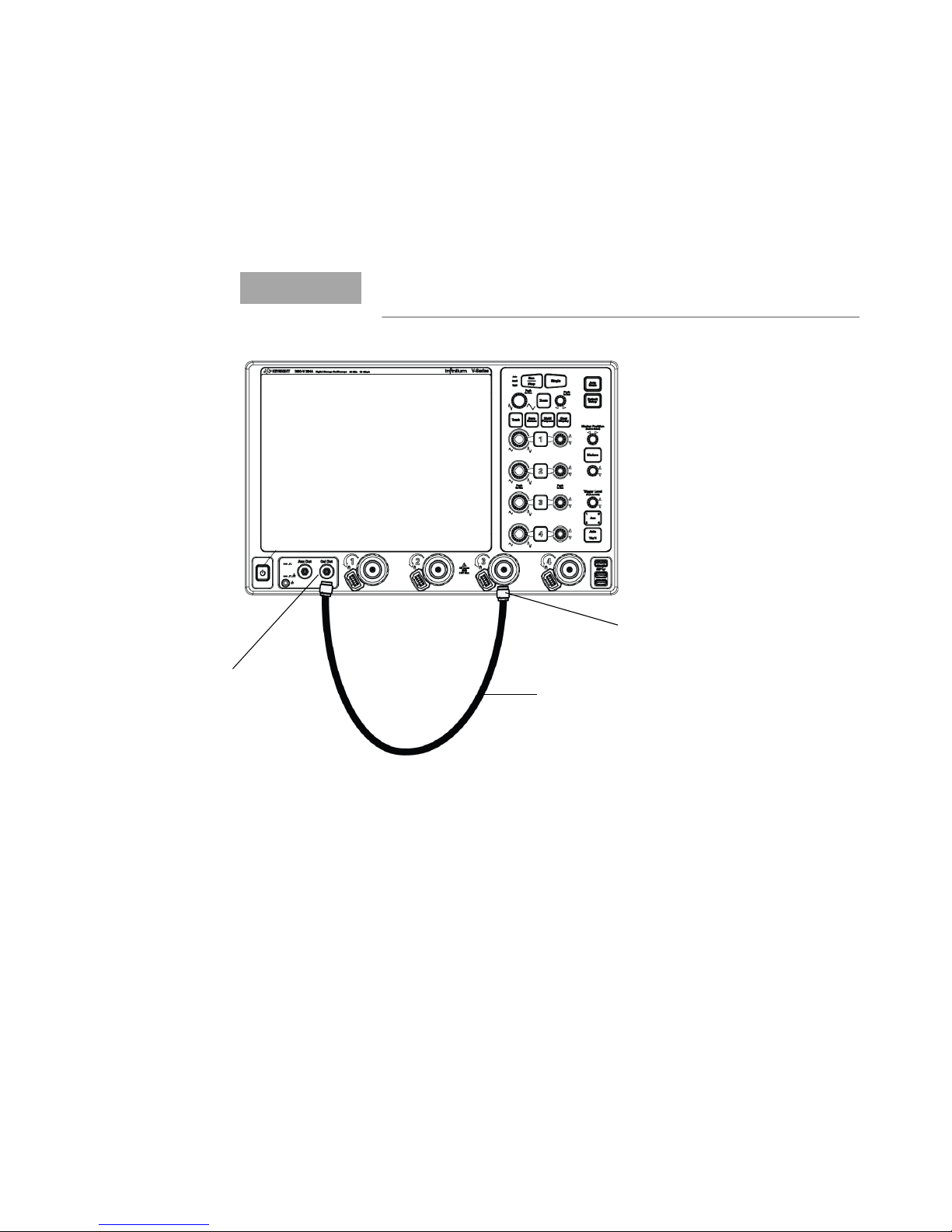
8 Performance Verification
NOTE
Calibration
Cable
Cal Out
Connector
SMA f-f
Adapter
4 Connect the other end of the calibration coax cable to the Cal Out connector on
the front panel of the oscilloscope.
Use the 3.5mm or 2.92mm SMA female to female adapters to make
these connections to Cal Out and input channel of oscilloscope.
Figure 28 Calibration setup with the calibration cable
5 Press [Auto Scale] on the front panel.
6 Choose Setup > Acquisition, then select the Enabled checkbox for Averaging and set
the # of averages to 1024.
7 Set timebase to 2ns/div.
8 Choose Setup > Math Functions... or Math > Functions....
9 In the Function dialog box, select the tab of the function f1 to define it.
10 From the Function 1 listbox, select Math and then Differentiate.
82 N7020A and N7024A Power Rail Probes User’s Guide
Page 83
Performance Verification 8
11 From the Source 1 drop-down listbox, select the input channel of the oscilloscope
to which you connected the calibration cable. This will become the source on
which the f1 function will be performed.
12 Deselect the Low Pass and Align Phase checkbox.
13 Select the tab of the function f2 to define it.
14 From the Function 2 listbox, select FFT.
15 Turn the function display on for f2 by selecting the On checkbox.
16 Set the source for f2 to Function 1 and close the Function dialog box. The
oscilloscope is configured as displayed in the figure below.
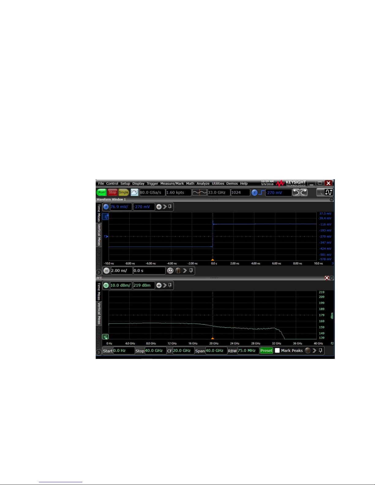
Figure 29 Oscilloscope’s user interface as per the functions defined
17 In the f2 display area, set the following for f2:
• stop frequency to 10 GHz.
• vertical scale to 3dbm/div.
N7020A and N7024A Power Rail Probes User’s Guide 83
Page 84
8 Performance Verification
18 Record and save the frequency response of the Cal Out step through the attached
calibration coax cable. To do this, perform the following steps.
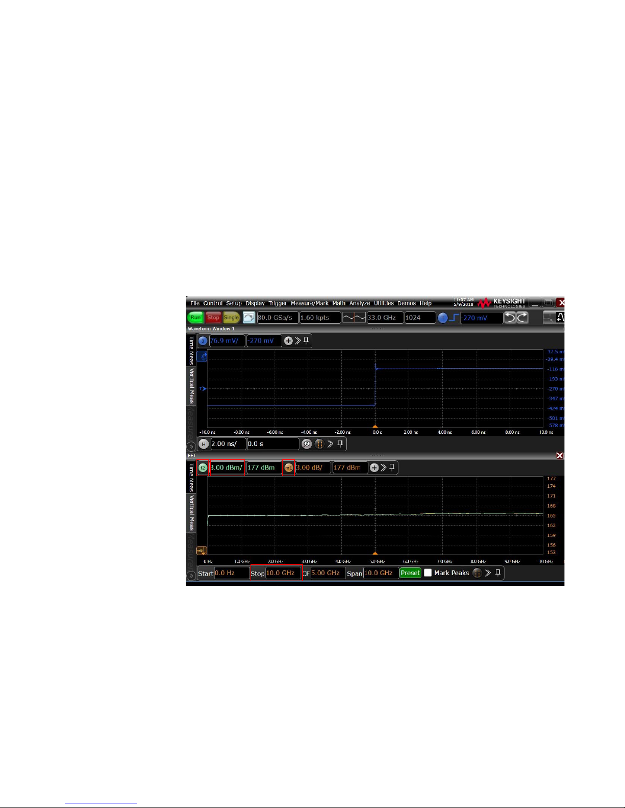
a The f2 trace is displayed at the bottom of the screen. Drag the f2 trace to the
b Save the frequency response of the coax cable by right-clicking the f2 trace
c For ease of comparison, drag the memory 1 trace into the same window as
center graticule.
and saving it to memory 1. This will allow you to later compare the saved
frequency response of the Cal Out step through the attached calibration
coax cable with the frequency response of the N7024A probe (done in steps
that follow).
the f2 trace. Close the window that was initially displayed for memory 1.
Figure 30 Frequency response of the Cal Out step through the attached coax cable
84 N7020A and N7024A Power Rail Probes User’s Guide
Page 85
Performance Verification 8
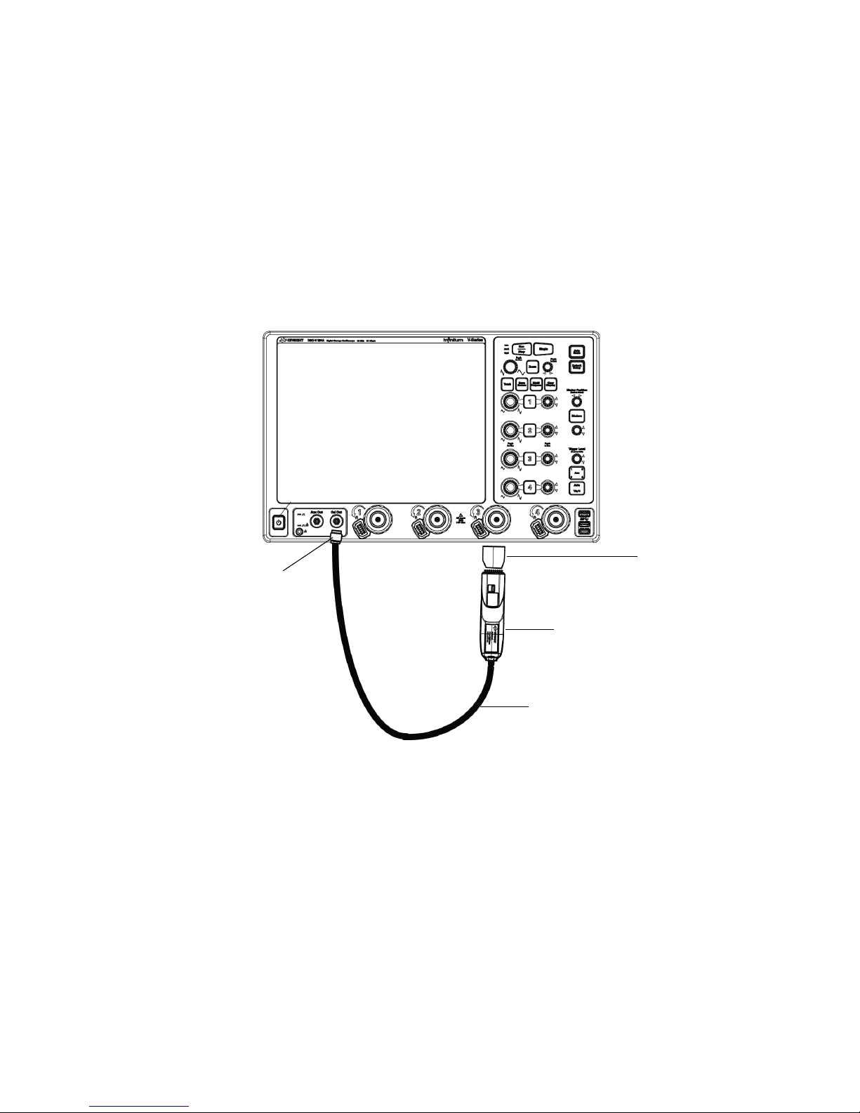
Calibration
Cable
SMA f-f
Adapter
N7024A
Probe
N5422A
Adapter
19 Check the frequency response of the N7024A probe. To do this, perform the
following steps.
a Disconnect the calibration coax cable and any adapters that you attached to
the input channel of the oscilloscope.
b Connect the N7024A probe to the input channel and calibration coax cable.
You may need to use the N5442A adapter with the probe in case you are
using a V-series or a Z-series oscilloscope.
Figure 31 Calibration setup with the N7024A probe and calibration cable
c Choose Setup > Probe Configuration....
d Select the tab of the oscilloscope’s input channel to which the probe is
connected.
e In the Probe Head block, click Select Head.... Select Generic:User Cable to
configure the oscilloscope to not consider any loss from the N7022A main
cable or any probe browsers. Click OK and close the dialog.
N7020A and N7024A Power Rail Probes User’s Guide 85
Page 86
8 Performance Verification
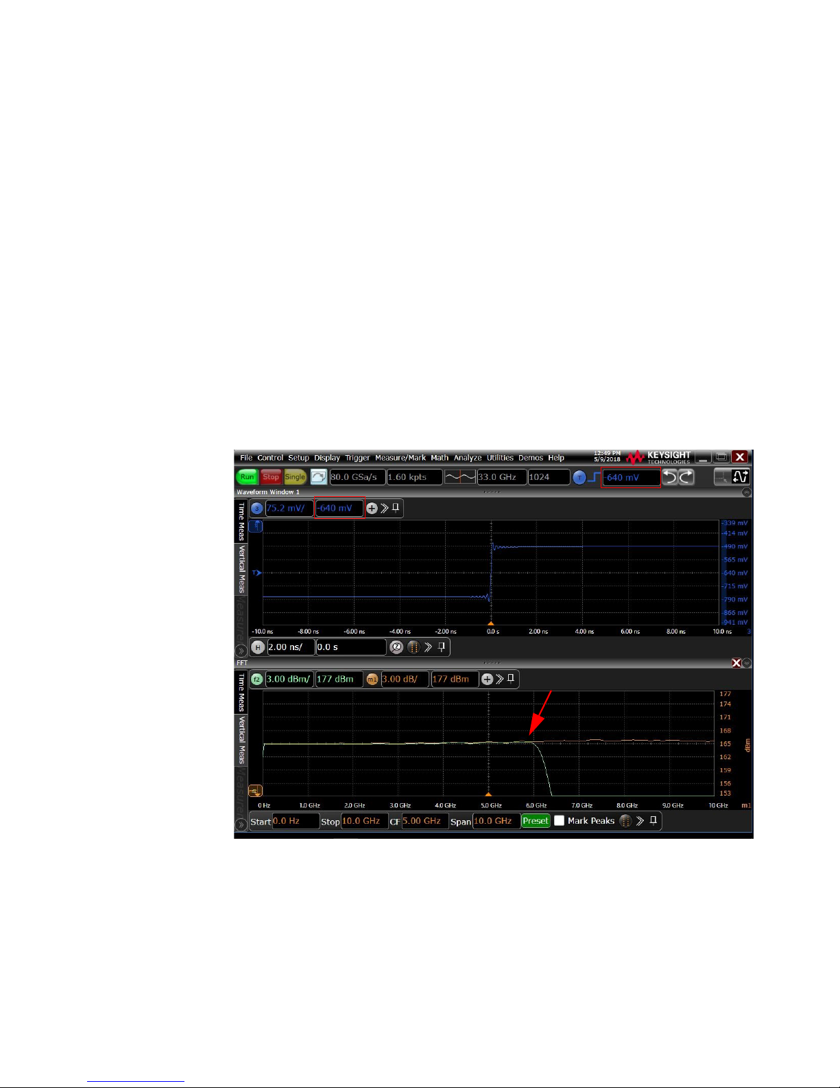
f Set the channel offset for the oscilloscope to -640mV and the trigger level to
g The f2 trace now has the frequency response with the N7024A probe
h The frequency response of the N7014A probe is the difference between the
Notice that in the figure below, the N7024A probe passed the bandwidth
verification test as the frequency response of the probe s not above 3db at 6
GHz or below.
-640mV as displayed in Figure 32.
attached. The already saved and displayed memory 1 trace has the
frequency response of the coax cable. For comparison, grab the f2 trace and
align it with the memory 1 trace, if needed as displayed in Figure 32.
f2 trace and memory 1 trace. Verify whether or not this difference is less
than 3db at 6 GHz or below. If it is less, then the probe passes the test.
Figure 32 Frequency response of the N7024A probe
86 N7020A and N7024A Power Rail Probes User’s Guide
Page 87
Performance Test Record
Serial #:
Date:
Tested by:
Recommended Next Test Date:
Table 16 Bandwidth Test Results
Test Limits Result Pass/Fail
Less than 3 dB at 6 GHz or below
To verify if the N7022A main cable is damaged
At times, a damaged N7022A main cable may cause the N7022A+N7024A probe
system to not meet its bandwidth specification even when the N7024A has passed
the bandwidth verification test described in the previous section.
Performance Verification 8
When the N7022A cable is connected to the N7024A probe, the oscilloscope
utilizes a DSP correction filter to adjust the system response and correct the
nominal signal loss from the N7022A main cable. In the case of a damaged main
cable, this loss is more than the correction. Consequently, the probe may not meet
its bandwidth specification when used in combination with such a damaged cable.
In such situations, it is recommended to verify whether or not the N7022A main
cable is damaged using the procedure given below and replace the cable.
Prerequisites
The following are the prerequisites before you start verifying if the N7022A cable is
damaged.
• The N7024A probe should have passed the bandwidth performance verification
test using the procedure given in the previous section.
• The hardware and software setup configured at the completion of the N7024A
bandwidth performance verification procedure should be retained for this
procedure.
Procedure
1 From the hardware setup used in the N7024A bandwidth verification test
(Figure 31), disconnect the calibration coax cable from the N7024A probe.
N7020A and N7024A Power Rail Probes User’s Guide 87
Page 88
8 Performance Verification
N7022A Main
Cable
SMA f-f
Adapter
N7024A
Probe
N5422A
Adapter
Calibration
Cable
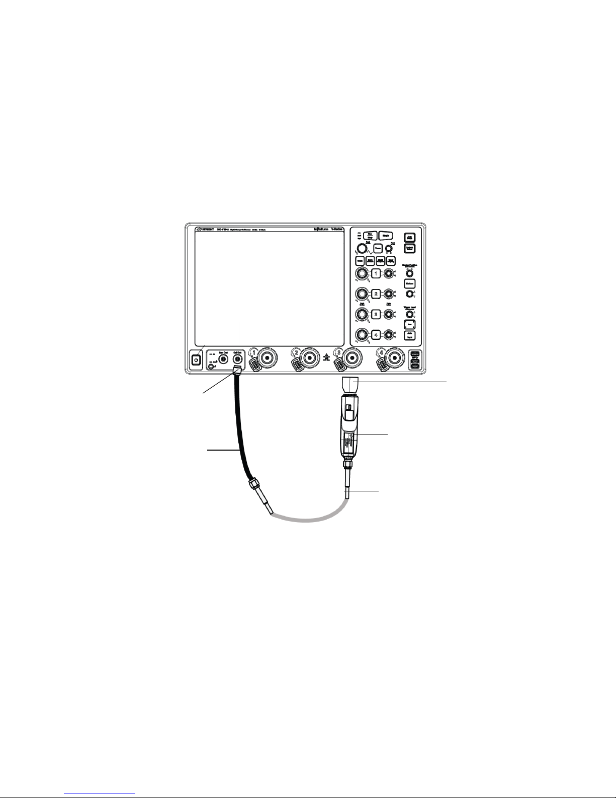
2 Connect the calibration coax cable to the N7022A main cable that you want to
verify. Use an SMA f-f adapter to connect the two cables.
3 Then connect this main cable to the N7024A probe.
This hardware setup is illustrated in the figure that follows.
Figure 33 Calibration setup with the N7024A probe, main cable, and calibration cable
4 Choose Setup > Probe Configuration....
5 Select the tab of the oscilloscope’s input channel to which the probe is connected.
6 In the Probe Head block, click Select Head.... Select N7022A:N7024A Main Cable to
configure the oscilloscope to consider the nominal loss from the N7022A main
cable. Click OK and close the dialog.
7 The f2 trace now has the frequency response with the N7024A probe attached to
88 N7020A and N7024A Power Rail Probes User’s Guide
the N7022A main cable. The already saved and displayed memory 1 trace has the
frequency response of the coax test cable. See Figure 32.
Page 89
Performance Verification 8
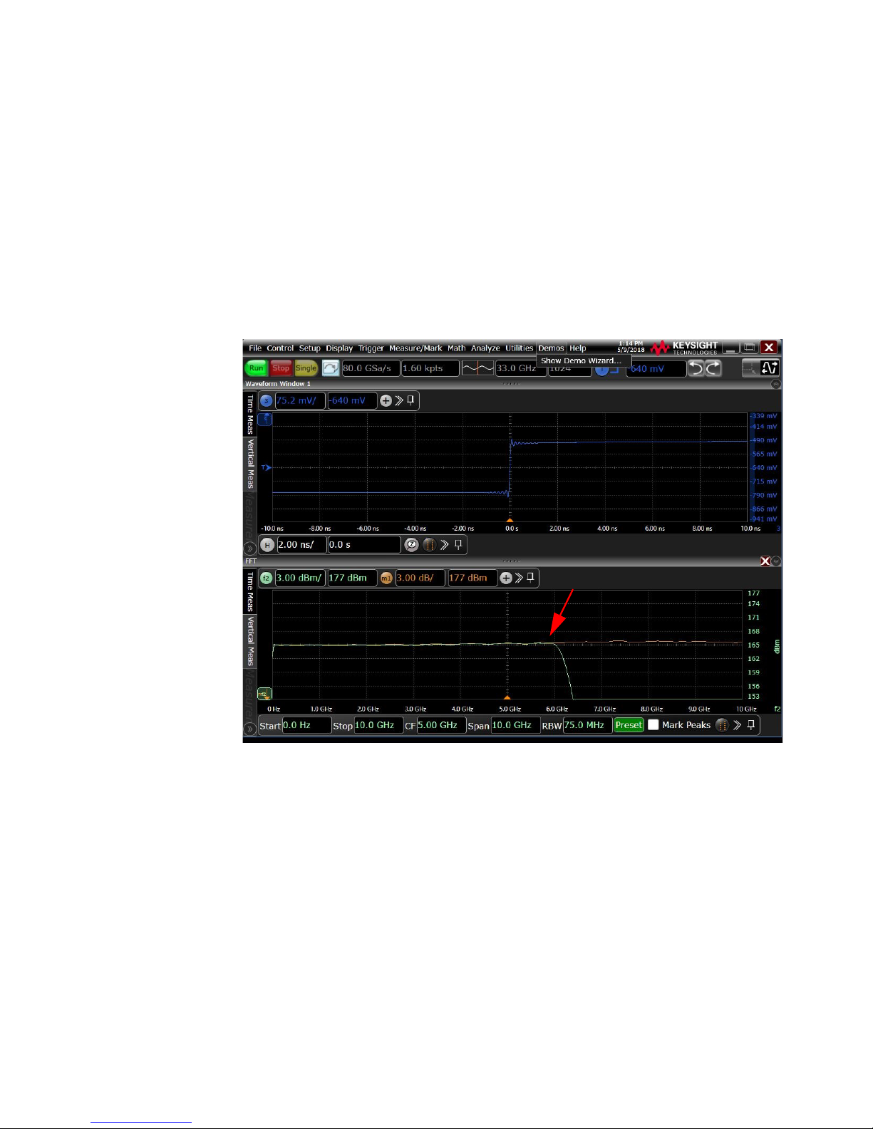
8 Consider the N7022A main cable as damaged if either of the following is true:
• The difference between the f2 trace and memory 1 trace is more than 3db at
6 GHz or below.
• The difference between the f2 trace and memory 1 trace is less than 3db at 6
GHz or below but the f2 trace is clearly different from the f2 trace displayed
in the sample figure below.
Figure 34 Frequency response of the N7024A probe with the N7022A main cable
N7020A and N7024A Power Rail Probes User’s Guide 89
Page 90

8 Performance Verification
90 N7020A and N7024A Power Rail Probes User’s Guide
Page 91

Index
A
accessories, 9
static-safe, 53
altitude, 26, 30
AutoProbe 1 interface, 6
B
bandwidth, 27, 31
browser accessories, 12
C
calibration setup, 85, 88
care, probe, 7
CE mark, 37
characteristics, 25
cleaning, 22
compatible oscilloscopes, 16
D
damaged cable, 87
DC input resistance verification, 78
input resistance, 27, 31
inspecting, 20
K
Keysight Technologies, contacting, 24
M
Mechanical Characteristics, 27, 32
N
N7024A standard accessories, 10
N7032A, 11
N7033A, 11
O
orderable accessories, 14
Orderable Parts, 14
oscilloscope
compatibility, 16
P
S
service, 23
SMA Adapter, 11
standard accessories, 11
static-safe accessories, 53
T
temperature, 26, 30
testing
input resistance, 78
W
warranted bandwidth verification, 81
WEEE Directive, 37
E
electrical specifications, 27, 31
environmental specifications, 26, 30
G
grounding probe, 20
H
humidity, 26, 30
I
input impedance model, 70
N7020A and N7024A Power Rail Probes User’s Guide 91
performance test record, 79, 87
probe
cable care, 7
cleaning, 22
grounding, 20
inspecting, 20
service, 23
Probe Calibration dialog box, 58
probe tips, 12
R
repair, 23
resistance testing, 78
returning for service, 23
Page 92

Index
92 N7020A and N7024A Power Rail Probes User’s Guide
 Loading...