

Page 1

Insert the
Keysight
N6841A
Title in this
RF Se
Space
nsor
Page 2
Notices
Copyright Notice
© Keysight Technologies 2018
No part of this manual may be reproduced
in any form or by any means (including
electronic storage and retrieval or
translation into a foreign language) without
prior agreement and written consent from
Keysight Technologies, Inc. as governed by
United States and international copyright
laws.
Manual Part Number
N6851-90001
Edition
Edition 1.2, April 2018
Published by:
Keysight Technologies, Inc.
1400 Fountaingrove Parkway
Santa Rosa, CA 95403
Technology Licenses
The hardware and/or software described in
this document are furnished under a
license and may be used or copied only in
accordance with the terms of such license.
Declaration of Conformity
Declarations of Conformity for this product
and for other Keysight product may be
downloaded from the Web. Go to the
“Declarations of Conformity”
http://www.keysight.com/go/conformity.
You can then search by product number to
find the latest Declaration of Conformity.
U.S. Government Rights
The Software is “commercial computer
software,” as defined by Federal
Acquisition Regulation (“FAR”) 2.101.
Pursuant to FAR 12.212 and 27.405-3 and
Department of Defense FAR Supplement
(“DFARS”) 227.7202, the U.S. government
acquires commercial computer software
under the same terms by which the
software is customarily provided to the
public. Accordingly, Keysight provides the
Software to U.S. government customers
under its standard commercial license,
which is embodied in its End User License
Agreement (EULA), a copy of which can be
found at
http://www.keysight.com/find/sweula. The
license set forth in the EULA represents the
exclusive authority by which the U.S.
government may use, modify, distribute, or
disclose the Software. The EULA and the
license set forth therein, does not require
or permit, among other things, that
Keysight: (1) Furnish technical information
related to commercial computer software
or commercial computer software
documentation that is not customarily
provided to the public; or (2) Relinquish to,
or otherwise provide, the government
rights in excess of these rights customarily
provided to the public to use, modify,
reproduce, release, perform, display, or
disclose commercial computer software or
commercial computer software
documentation. No additional government
requirements beyond those set forth in the
EULA shall apply, except to the extent that
those terms, rights, or licenses are
explicitly required from all providers of
commercial computer software pursuant to
the FAR and the DFARS and are set forth
specifically in writing elsewhere in the
EULA. Keysight shall be under no
obligation to update, revise or otherwise
modify the Software. With respect to any
technical data as defined by FAR 2.101,
pursuant to FAR 12.211 and 27.404.2 and
DFARS 227.7102, the U.S. government
acquires no greater than Limited Rights as
defined in FAR 27.401 or DFAR 227.7103-5
(c), as applicable in any technical data.
Warranty
THE MATERIAL CONTAINED IN THIS
DOCUMENT IS PROVIDED “AS IS,” AND IS
SUBJECT TO BEING CHANGED WITHOUT
NOTICE IN FUTURE EDITIONS. FURTHER,
TO THE MAXIMUM EXTENT PERMITTED BY
APPLICABLE LAW, KEYSIGHT
TECHNOLOGIES DISCLAIMS ALL
WARRANTIES OF MERCHANTABILITY AND
FITNESS FOR A PARTICULAR PURPOSE.
KEYSIGHT TECHNOLOGIES SHALL NOT BE
LIABLE FOR ERRORS OR FOR INCIDENTAL
OR CONSEQUENTIAL DAMAGES IN
CONNECTION WITH THE FURNISHING,
USE, OR PERFORMANCE OF THIS
DOCUMENT OR OF ANY OF THE
PRODUCTS TO WHICH IT PERTAINS.
SHOULD KEYSIGHT TECHNOLOGIES
HAVE A WRITTEN CONTRACT WITH THE
USER AND SHOULD ANY OF THE
CONTRACT TERMS CONFLICT WITH
THESE TERMS THE CONTRACT TERMS
SHALL CONTROL.
Safety Information
A CAUTION notice denotes a hazard. It
calls attention to an operating
procedure, practice, or the like that, if
not correctly performed or adhered to,
could result in damage to the product
or loss of important data. Do not
proceed beyond a CAUTION notice
until the indicated conditions are fully
understood and met
A WARNING notice denotes a hazard.
It calls attention to an operating
procedure, practice, or the like that, if
not correctly performed or adhered to,
could result in personal injury or
death. Do not proceed beyond a
WARNING notice until the indicated
conditions are fully understood and
met.
Page 3

1 RF Sensor User Guide
Edition History
Edition
Summary of Change
Written by
Date
1.2
Reference oscillator,
Temperature limits,
Troubleshooting
D. Carpenter
2018-04-24
1.1
Reformatted/Edited
D. Carpenter
2018-01-03
1.0
Initial version
R. Shen
2014-08-01
Page 4

Contents
Introduction ............................................................................. 3
Sensor Management Software ............................................... 4
Managing Sensors .................................................................. 6
Finding Sensors on the Local Subnet .......................................... 6
Modifying a Sensor’s Network Parameters .................................. 7
Rebooting a Sensor ...................................................................... 8
Adding a Sensor to the SMS Sensor List ..................................... 8
Adding a Sensor that is not on the Local Subnet ........................ 9
Discovering an RF Sensor’s IP Address ...................................... 10
SMS Sensor List .......................................................................... 10
Deleting a Sensor on the SMS Sensor List ................................ 11
Dashboard View .......................................................................... 11
Editing the Sensor Configuration ......................................... 14
Sensor Hardware and Identification ........................................... 14
Time Synchronization Data ......................................................... 15
Location Data .............................................................................. 15
Cable Attenuation Data .............................................................. 21
Amplifier / Filter Data ................................................................. 22
Network Configuration Data ....................................................... 22
GPS Configuration and Status ................................................... 23
1588 Data.................................................................................... 26
Reference Oscillator ................................................................... 26
Embedded Apps (beta) ............................................................... 28
Frequency Extender .................................................................... 29
Multiple Narrowband Channels .................................................. 30
Running the RF Sensor’s Self-Test ...................................... 31
Configuring the Map ............................................................. 33
Managing Sensor Firmware .................................................. 35
Using the Spectrum Monitor ................................................ 37
Using the Radio Receiver ..................................................... 38
Launching an Application from Within SMT ........................ 38
2 RF Sensor User Guide
Page 5
3 RF Sensor User Guide
Introduction
The Sensor Management Tool (SMT) is used to configure, and manage
Keysight RF Sensors. The SMT provides both a simple interface to discover,
configure, and update sensors, and a launcher to launch sensor applications.
This table lists other manuals pertinent to the Keysight N6841A RF Sensor.
Part Number
Title
Pub Date
N6841-90000
N6841A Quick Start Guide
Sep 2017
N6841-90002
N6841A RF Sensor Installation Guide
Sep 2017
N6854-90000
Geolocation Server User Guide
Sep 2017
N6851-90004
System Planning Tool User’s Guide
Sep 2017
Application Programming Overview
(SAL Reference)
Sep 2017
Be aware of these safety symbols found in the Keysight RF Sensor documents:
The exclamation point within an equilateral triangle is
intended to alert the user to the presence of important
operating and maintenance (servicing) instructions.
Page 6
4 RF Sensor User Guide
Sensor
Management
Software
The SMT uses another Keysight software product, the Sensor Management
Server (SMS), which runs as a Windows service, handling requests from the
SMT client and maintaining a database entry for every sensor it manages. To
use the SMT, connect the SMT to an instance of SMS, either running on a
distant host or running on the local host.
Sensor Management Server (SMS)
SMS is installed on a computer during a normal Keysight RF Receiver software
installation. After it is installed, SMS is launched as a service when the server
is rebooted. No further steps need to be taken.
Verify SMS is running on a server:
1. Click: Start > All Programs > Accessories > System Tools > System
Information
2. The System Information tool displays a series of categories in its
System Summary area (left of the window).
3. In the System Summary, double-click on the Software Environment
4. Click the Services sub-category under the Software Environment
5. The System Information tool displays a list of currently-running
services on the right.
6. Verify the service "Keysight SMS", under the column "Display Name",
is present and running.
Starting SMT
To launch the Sensor Management Tool (SMT), use the following steps:
1. Click: Start> All Programs> Keysight RF Sensor> Sensor Management
Tool
2. See that the SMT displays the splash screen.
3. See that the SMT displays the Dashboard window.
The SMT Dashboard is one of four main SMT windows. The other three are the
Map, the Configuration, and Spectrum Monitor. These windows are available
through the menu bar and through the Dashboard , Map , Configuration
, and Spectrum Monitor icons at the top of the window. The SMT will
open to display the widow that was active when it was last closed.
Connecting SMT to an SMS Server
The Sensor Management Tool connects to sensors through a Sensor
Management Server (SMS). The SMS can be running on a distant server, or
can run on a local machine.
Page 7
5 RF Sensor User Guide
Resource conflicts can occur when multiple instances of SMS
attempt to use the same sensor. To prevent these conflicts,
we recommended that users attach all instances of SMT to
the same instance of SMS. Having all installations of SMT
connect to the same instance of SMS can prevent resource
conflicts.
To connect an instance of SMT to an instance of SMS running on a distant
machine, enter the network name or IP address of the distant machine. If the
SMS is located on the local machine, connect to it using the shortcut
“localhost.” Connect to an instance of SMS using the following procedure.
Connect SMT to an SMS server:
1. Click on the Tools menu
2. Click on the Preferences menu entry
3. Click on SMS, on the left side of the Preferences screen
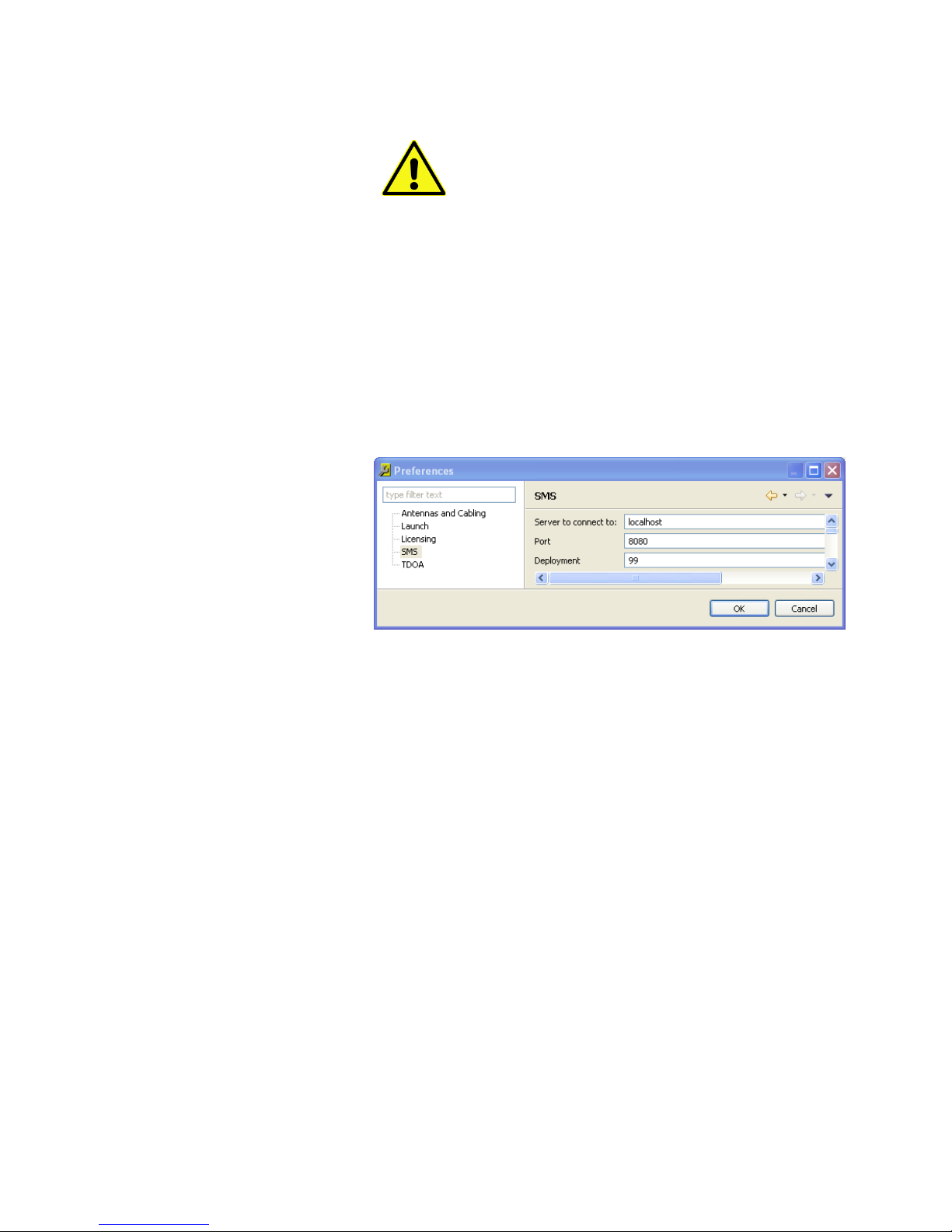
4. SMT displays the Preferences window seen below.
In the SMS preferences window, verify the following entries:
1. In the “Sever to Connect to:” dialog box, enter the IP address of the
server running the instance of SMS to use
To use an instance running locally, use localhost
To use an instance running on another computer, use the
computer’s IP address
2. In the “Port” dialog box, enter 8080
3. Click the Apply button, and then click the OK button.
Page 8
6 RF Sensor User Guide
Managing Sensors
SMS can discover sensors that exist on the same subnet as an instance of the
SMS, using multicast networking technology. The SMT allows users access to
this function. Note that sensors on the same subnet as the SMT, but not on the
same subnet as the SMS cannot be discovered using this function.
Note: To use one of the sensors in the Available list, it must first be assigned to
the SMS.
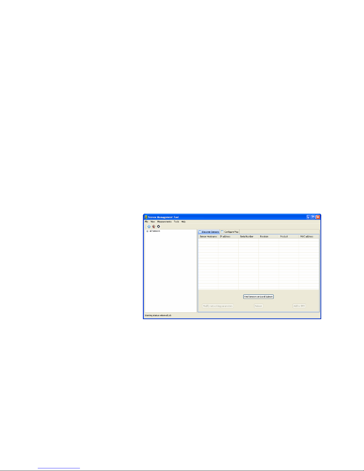
Finding Sensors on the Local Subnet
To discover sensors on the local subnet, from the SMT window perform the
following steps:
1. Click on the View menu
2. Click on the Configuration menu
3. Select the Discover Sensors tab on the right side of the window.
4. At the bottom of the window, click the “Find Sensors on Local
Subnet” button.
Once the “Find Sensors on Local Subnet” button is clicked, it is relabeled
to display, “Refresh sensor list.”
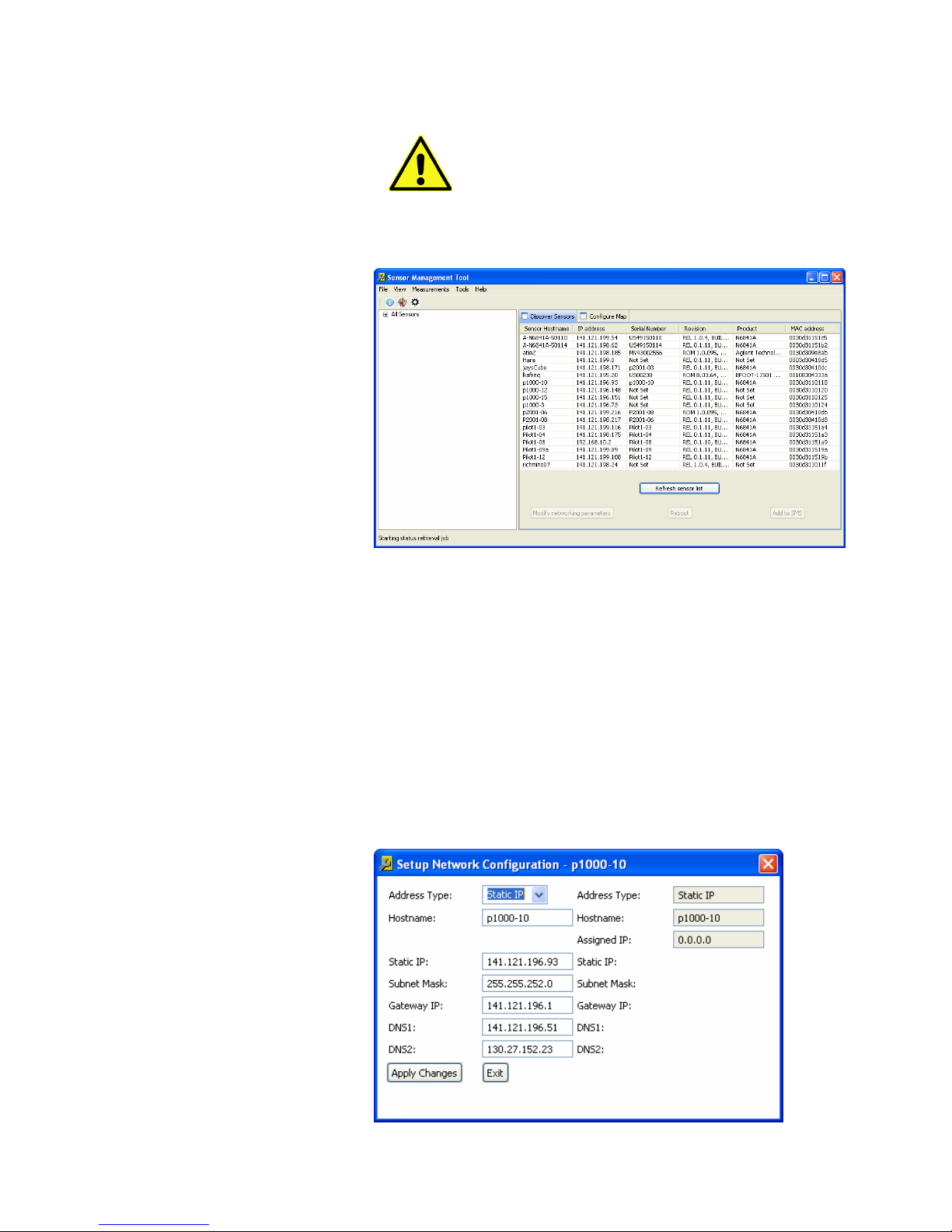
Clicking the “Refresh sensor list” button directs the SMS to find the sensors on
its local subnet and return the sensors’ information to the SMT. After a few
seconds, a list of the sensors that have been discovered is displayed on the
right side of the Configuration window. The list includes the sensor’s name, IP
address, MAC address, and Serial Number. The sensor’s name and its IP
address can be changed, but the MAC address and Serial Number cannot.
Since they are assigned to a sensor unit when it is manufactured. The sensor
serial number is visible on the outside of the sensor case.
When the SMT has completed filling the list of sensors, it changes the find
sensors button to “Refresh sensors list.” Clicking this button refreshes the list
of sensors, adding to the list newly attached sensors and removing from the
list disconnected sensors.
Page 9
7 RF Sensor User Guide
If the Microsoft Windows system is running a firewall, an
exception must be created in the firewall software to allow
SMS to communicate with the RF sensors.
Refer to the firewall documentation to learn how to create
an exception for SMS.
Clicking on a sensor list entry highlights that entry and enables the three
buttons at the bottom of the window. The three buttons are “Modify
networking parameters,” “Reboot,” and “Add to SMS.” To add a sensor not on
the local subnet, see section 4.5.
Modifying a Sensor’s Network Parameters
To modify a sensor’s configuration, add the sensor to the SMT Sensor List.
Note: It is sometimes necessary to modify a sensor’s network setting before
adding it to the Sensor List.
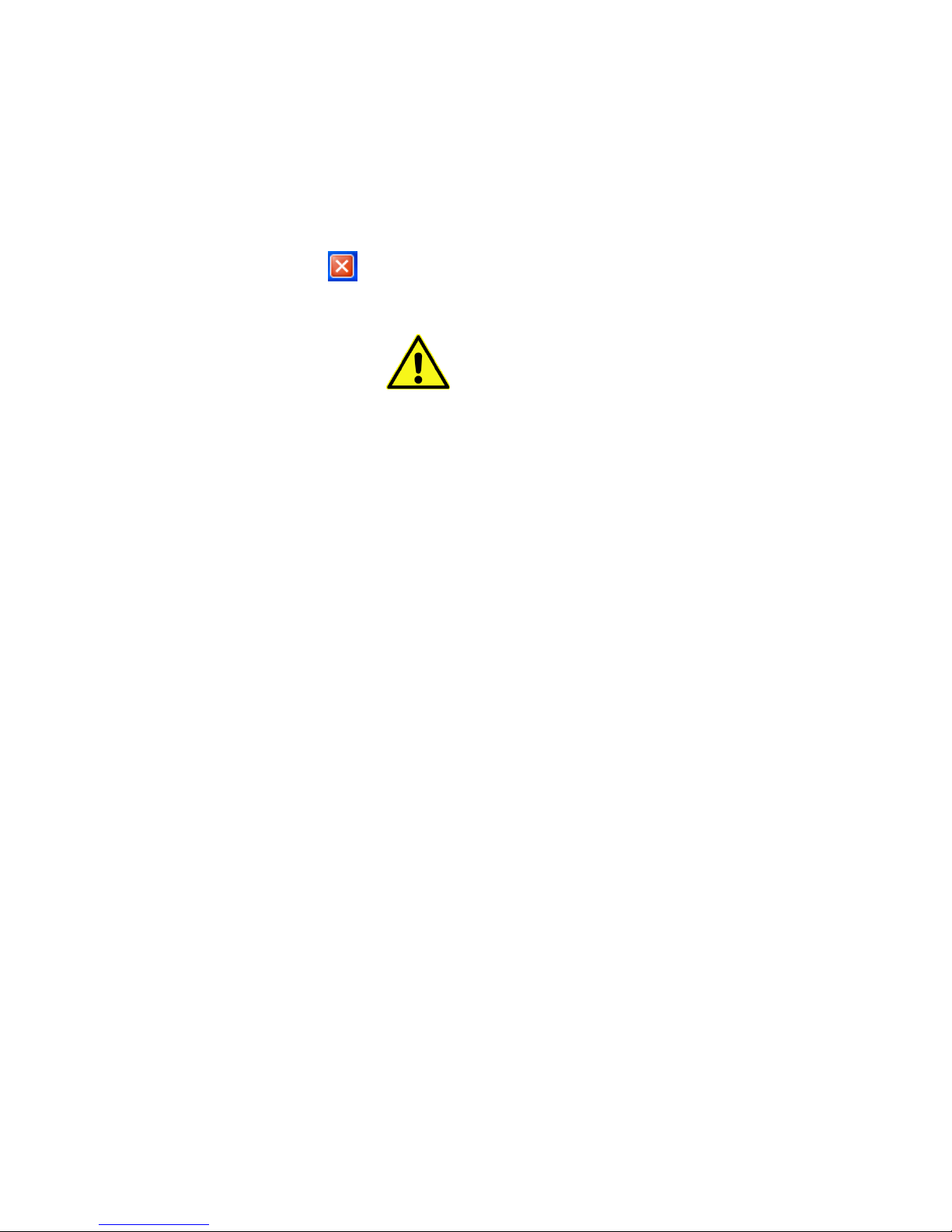
It is possible to reconfigure the network settings of a sensor in the discovered
list by clicking on the Modify Network Parameters button at the bottom of the
Sensor Management Tool’s window. This will display the Setup Network
Configuration window. Note that many of the network parameters that can be
set in this window can also be set using the Sensor Configuration dialog box
described later.
Page 10
8 RF Sensor User Guide
The Setup Network Configuration window is used to view and manually set the
sensor's network configuration. The window shows two sets of configuration
data. The values displayed in shaded boxes on the right-hand side of the
window are the values currently being used by the selected sensor. To change
these values, enter the desired values in the text entry boxes on the left, and
click the Apply Changes button.
To change these stored network values, enter the desired values in the text
entry boxes on the left, then click the Apply Changes button. The new values
are applied to the RF sensor and now appear in the shaded boxes.
To leave this dialog box without changing a sensor’s configuration, click the
box’s close button.
If Microsoft Windows changes focus (if another program
window is placed on top of the SMT window) before clicking
either the Apply Changes button or the Exit button, it is
possible to lose track of the dialog box and SMT can appear
to be hung. This is normal Windows behavior. If this
happens, minimize all open windows and maximize the SMT
window to restore the dialog box.
Rebooting a Sensor
To reboot an RF sensor, use the following steps:
1. From the Configuration window, click the Discover Sensors tab.
2. When the SMT displays the RF Sensors that are present on the
SMS’s local subnet, click to highlight the entry of the RF sensor to
reboot.
3. Click the Reboot button at the bottom of the window.
Adding a Sensor to the SMS Sensor List
Add a sensor, from the list of available sensors, to the instance of SMS being
used through the SMT.
Note: SMT does not show if the sensor is currently used by a different instance
of SMS. Having all installation of SMT connects to the same instance of SMS
can prevent conflicts where multiple instance of SMT vie for the same sensors.
To add a sensor to SMS, use the following steps.
1. From the list of available sensors in the Configuration window, select
the sensor to use and click on it to highlight its entry.
2. At the bottom of the Configuration window, click on the button
marked, “Add to SMS.”
Click the “Add to SMS,” which causes the selected sensor to be displayed in
the “All sensors” list on the left of the Configuration window. To expand the All
sensors list, click the “+” button to the left of the “All sensors” heading.
Page 11
9 RF Sensor User Guide
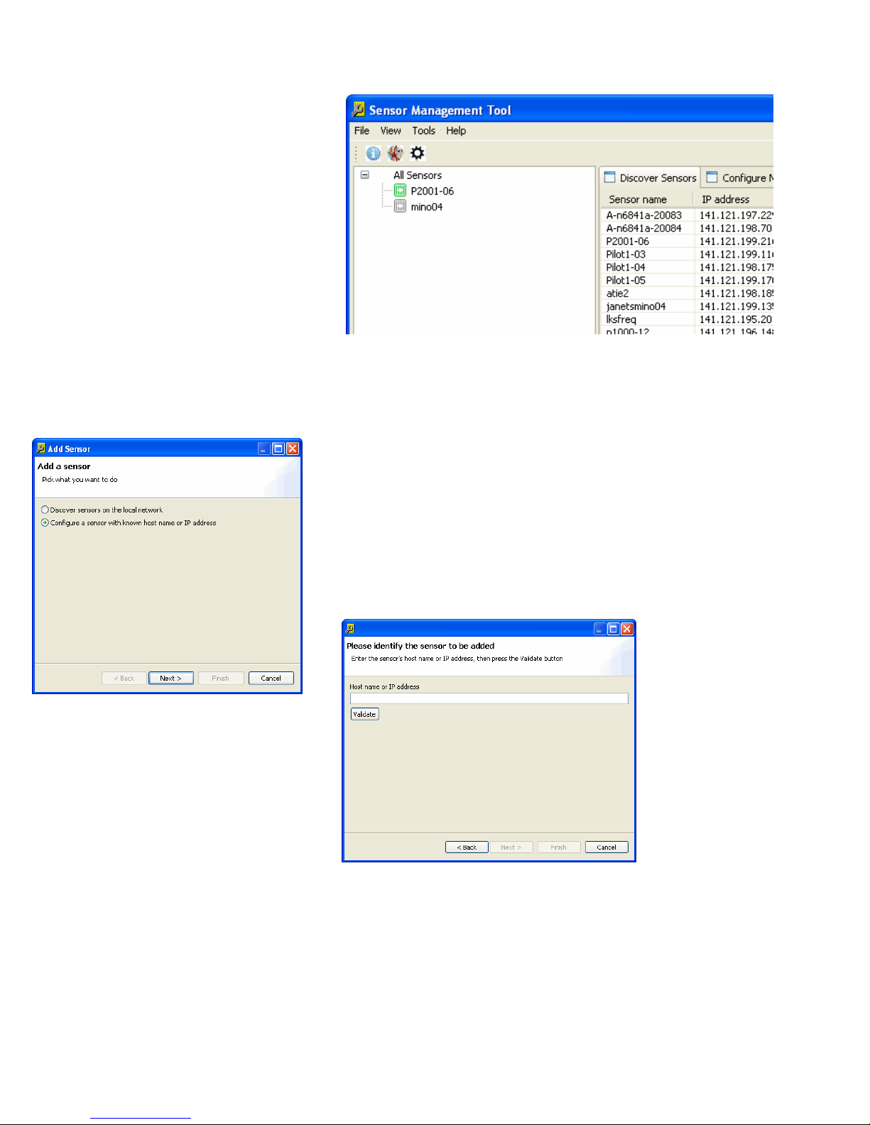
Each entry in the sensor list is headed by a sensor icon. A green icon indicates
that the SMS has recently received a status message from the sensor and that
it is generally functional. A gray icon indicates that the SMS has not received a
status message from that sensor for a predetermined time period. A red icon
indicates that SMS has detected a problem with that sensor.
Adding a Sensor that is not on the Local Subnet
To add an RF Sensor that is not on the local subnet (and is therefore not
discoverable by the SMT), the sensor’s IP address must be known.
If the sensor’s IP address is known, use the following procedure.
1. Click Tools > Add sensors….
2. Select Configure a sensor with a known host name or IP address.
3. Click Next.
4. Enter the IP address in the text entry box
5. Click the Validate button.
6. When SMT has validated that it can communicate with a RF sensor at
the IP address, the Next button becomes active. Click Next.
7. In the text entry box, enter a descriptive name for the sensor.
8. Click the Finish button to save the entry and to place the sensor in
the All Sensors list.
Page 12

10 RF Sensor User Guide
Discovering an RF Sensor’s IP Address
In some applications, an RF Sensor is located locally, but is on a different
subnet than the workstation or laptop that is running SMS. In this case, there
is a method to quickly determine the sensor’s IP address. Once the sensor’s IP
address is known, add the sensor directly to the All Sensors list by using the
Tools > Add Sensor dialog box.
Note: The following procedure requires an Ethernet crossover cable or a
crossover adapter plug. This procedure can also be carried out by using
standard internet cables routing through an Ether net hub or switch.
Use the following steps, if using an Ethernet crossover cable, to discover an RF
Sensor’s IP address:
Disconnect the RF Sensor from its Ethernet connection.
1. Using an Ethernet crossover cable, connect the sensor directly to the
workstation or laptop that will run SMT.
2. Start SMT.
3. If necessary, set the SMS preferences to “localhost.”
Note: While connected to an RF Sensor directly, it is not possible to launch
Surveyor or block tools.
4. Click on the Configuration icon.
5. Select the Discover Sensors tab on the right of the window.
6. At the bottom of the window, click the “Find Sensors on Local
Subnet” button.
7. The sensor’s information, including its IP address, is displayed in the
Discovered Sensor list. Make a note of the IP address.
8. Disconnect the RF Sensor from the laptop, and reconnect it to its
working Ethernet connection.
9. If necessary, reset the SMS preferences to the desired instance of
SMS.
10. Connect the workstation or laptop back into its proper Ethernet
connection.
11. Close and re-start SMT.
12. Follow the steps listed in “Adding a sensor that is not on the Local
Subnet.”
SMS Sensor List
When a sensor is added to the “All sensors” list, changes are made in the
sensor and in the SMS itself. The sensor is given the network address for the
instance of SMS that is being used. The SMS adds the sensor to its database.
With these changes, the sensor knows with which instance of SMS to
communicate and the SMS knows to expect data from this sensor.
When these steps are completed, the sensor begins sending its status
information to the SMS and the SMS communicates that status with the SMT.
The sensor’s general status is displayed on the SMT Configuration window as
an icon next to the sensor name in the All Sensor list. A green icon indicates
that the SMS has recently received a status message from the sensor and that
it is generally functional. A gray icon indicates that the SMS has not received a
status message from that sensor for a predetermined time period. A red icon
indicates that SMS has detected a problem with that sensor.
Page 13
11 RF Sensor User Guide
Note: The SMS list displays sensor status using the gray icon even if a sensor
is disconnected from the network. The names of disconnected sensors can be
deleted from the sensor lists using the Configuration menu.
Deleting a Sensor on the SMS Sensor List
To remove a sensor from the SMS sensor list (making it available for other
SMS instances), use the following steps.
A sensor can be deleted from the SMS sensor list by clicking on the Tools
menu, or by right-clicking on the appropriate sensor’s icon.
To delete a sensor in the “All sensors” list by right-clicking, use the following
steps.
1. Right click the name of the sensor to be deleted.
2. From the right-click menu, click on “Delete Sensor(s).”
To delete a sensor in the “All sensors” list using the Tools menu, use the
following steps.
1. Click to highlight the name of the sensor to configure.
2. In the menu bar, click Tools > Sensor > Delete Sensor(s).
Dashboard View
Once the system has the sensors of interest attached to the controlling SMS,
the Dashboard View can be used for a high-level view of the status of the
sensors in the system. Right clicking on any of the sensors in this view will
display the configure panels, for more detailed views of settings for that
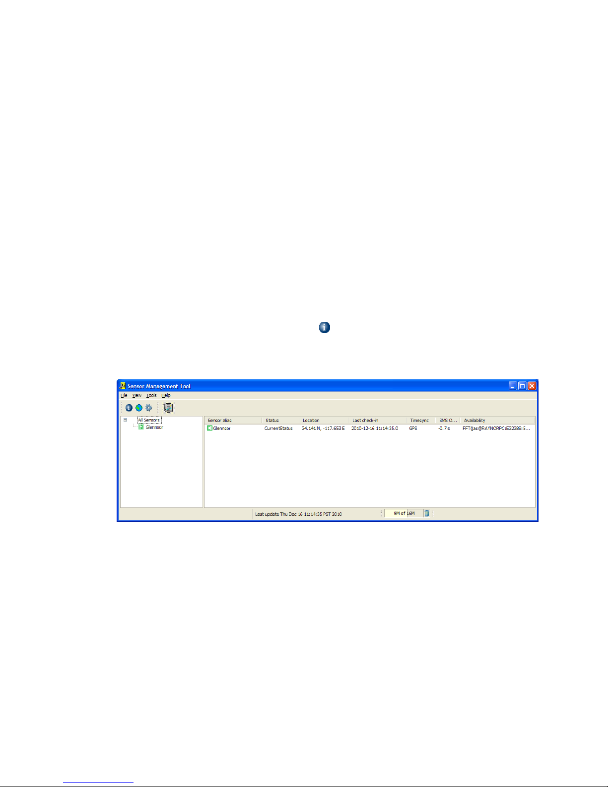
sensor. The Dashboard View looks as follows:
A description of the Dashboard fields are as follows:
Sensor alias – is the abbreviated name given to the sensor when it
was added to SMS.
Status:
Unknown –The sensor has not checked in with SMS in some
time. The sensor is likely either offline, has been taken by a
different SMS while the current SMS was off line, or there is a
communication problem.
CurrentStatus – The sensor’s communication link to SMS is
working well.
Connected – The link from SMS to the sensor has been
established but SMS has not heard back. This is should be very
transient state, lasting less than 1 sec.
Page 14

12 RF Sensor User Guide
Updating Firmware – The sensor is in the processing of updating
the firmware. (The power to that sensor should not be cycled
during this process).
Rebooting – After new firmware is loaded, the sensor will reboot,
and reconnect to SMS. The state also goes to “Rebooting” if a
reboot is invoked manually, either from the configuration dialog
or the Auto Discovery View.
Location – This is the latitude and longitude of each sensor as
currently configured.
Last check-in – This is the last time, in SMS time, that the sensor
communicated with SMS. This is typically once per minute.
Timesync – This shows the synchronization mode configured in the
sensor.
GPS – GPS based time synchronization
GPS/ 1588 GM – The sensor’s time comes from GPS, but the
sensor also provides a sense of time to other IEEE-1588
connected nodes as a Grand Master.
IEEE 1588 – The sensor’s time is provided over the LAN using
IEEE-1588.
None – The sensor has time synchronization turned off.
SMS Offset –This shows the time difference between the sensor and
the SMS. If this time offset is greater than 2 seconds, a yellow
warning triangle appears. This may impact the responsiveness of the
system to time triggered measurements. It can be addressed by
setting the PC time to sensor’s time source. If the sensor is a 1588
grandmaster (and not a GPS/1588 GM) setting the sensor time to the
SMS time, using the Time Synchronization configure panel is helpful.
Availability –This field shows if a sensor is locked and which
application and PC name holds the lock.
The sensor icons can be Red, Green or Gray. If a sensor icon is Green, it
synchronized, and ready to make measurements. If a sensor icon is Gray, it is
no longer communicating with the local SMS. If a sensor icon is Red, by
positioning the mouse pointer over the icon a status string will be displayed:
Time questionable: the sensor’s time synchronization operation has
not stabilized
GPS Antenna Problem: In most cases, the GPS antenna has not been
connected
Insufficient GPS Satellites: GPS synchronization is suspect because
the antenna is not receiving sufficient satellites to perform the
computation
Reference Oscillator Adjustment needed: This indicates the reference
oscillator is more than 10 ppb off in frequency compared to the time-
sync source (e.g. GPS or 1588 master). If the “Reference Oscillator
Adjustment” is in manual mode use the “Adjust Ref. Osc. now” button
(see section 5.9). If in automatic mode, the sensor will perform this
adjustment every 10 minutes until no longer needed.
GPS holdover expired (now drifting): After 3 minutes of not tracking
satellites the GPS module will enter the “drifting” state.
CPU Overload: This occurs when the sensor's CPU is overloaded and
is unable to service all tasks in a timely manner. It's 1588 timing may
be degraded.
Page 15

13 RF Sensor User Guide
Temperature Limits
The N6841A RF Sensor is specified to work from -15 °C to +55 °C ambient
temperature. In this temperature range the product will operate and meet
specification. There is approximately a 15 - 20 °C difference from external to
internal temperatures.
Internal RF Sensor temperature is considered questionable when it exceeds
70°C (High Temp) or below -30°C (Low Temp)
If internal RF Sensor temperature is 80°C (Power Down Temp) the power is
reduced, and measurement services are suspended. Power to the RF boards is
shut down and only the processor board remains powered on.
If internal RF Sensor temperature is 85°C (Power Off Temp), the power to all
boards is shutoff completely, with no communications with the RF Sensor or
ability to perform a software reboot. A power cycle, in addition to reduced
temperature, is required to resume operation.
The RF Sensor internal temperature is checked every 180 seconds. If the
temperature has been reduced to 65°C (Power Back Up Temp), the RF board
power supply will be re-established, and the RF Sensor can resume
measurements.
Recommendations to correct or prevent exceeding temperature limits:
If the inside temperature of the RF Sensor is exceeding the limits mentioned
above and shutting down, try installing a sun shield or move the sensor so it is
not in direct sunlight.
If the inside temperature RF sensor is below the limits mentioned above and
will not start, try placing it in an insulated enclosure with a small heat source,
such as a light bulb.
Summary of RF Sensor internal temperature limits, indicators and
actions:
+70 °C – generates a questionable High Temperature Alarm
-30 °C – generates a questionable Low Temperature Alarm
+80 °C – Is the Power Off Temperature limit. Power is reduced and
measurement services are suspended. Communication to the sensor
remains active and the processor board keeps power.
+65 °C - Power Back Up Temperature - Power is restored and
measurement services are resumed. Power is restored to the RF
boards.
+85 °C - Power Off Temperature - All power supplies are shut down
completely at this temperature, Sensors temperature must be lowered
to less than 65 °C and an RF sensor power cycle is required to restore
operation.
Page 16
14 RF Sensor User Guide
Editing the Sensor
Configuration
When a sensor arrives from the factory, it will not be properly configured for
the network. Sensors that are assigned (that is, in the “All sensors” list) can be
configured using SMT. Sensors are configured using the Configuration menu.
The configuration menu can be displayed by clicking on the Tools menu, or by
right-clicking on the appropriate sensor’s icon.
To configure a sensor in the “All sensors” list by right-clicking, use the
following steps.
1. Right click the name of the sensor to configure.
2. From the right-click menu, click on “Configure.” See the Sensor
Configuration dialog box.
To configure a sensor in the “All sensors” list using the Tools menu, use the
following steps.
1. Click to highlight the name of the sensor to configure.
2. In the menu bar, click Tools > Sensor > Configure. See the Edit
Sensor dialog box.
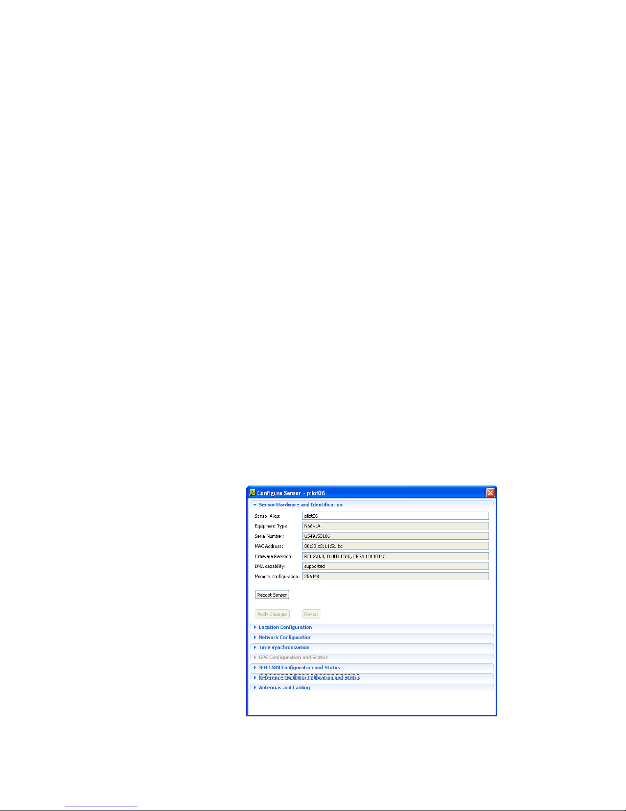
The Edit Sensor dialog box contains several views. Each view is used to
change some aspect of the selected sensors configuration. To change to any
of the views, click on the name of the view. Clicking on a view name displays
that view. Clicking on the view name a second time hides that view.
Sensor Hardware and Identification
This view of the configuration dialog box is used to change the sensor’s name
and several other values. This view is also used to update a sensor’s firmware
and reboot the sensor. It is also possible to remove the sensor from the SMS
assignment list.
Note: When entering data in the Sensor Hardware and Identification dialog
box, remember to click the “Finished” button before exiting the view.
Page 17
15 RF Sensor User Guide
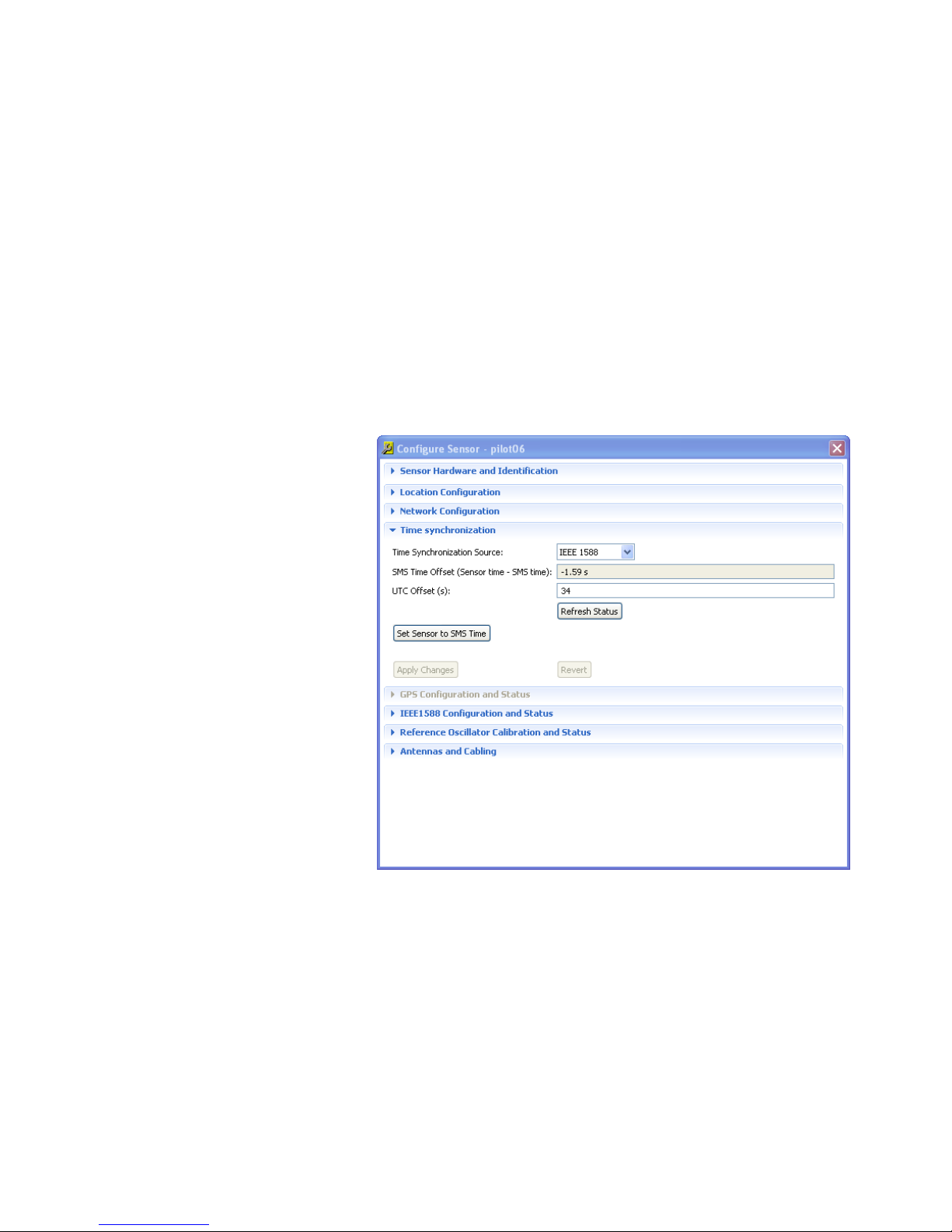
Time Synchronization Data
The Time synchronization Data view of the configuration dialog box is used to
specify the source for time synchronization data. Synchronization is necessary
for measurements such as Keysight Time Difference of Arrival (A-TDOA.) The
possible time synchronization sources are:
IEEE 1588 – Network-based precision time protocol. Selecting this
option enables the “1588 Data” view at the bottom of the dialog box.
GPS – GPS-based timing protocol.
GPS /1588 GM– The sensor will gain its timing from GPS and
provide timing to other sensors on the LAN via IEEE-1588.
None – No time protocol.
The SMS Time Offset shows the difference of the sensors’ sense of time and
that of SMS.
The UTC offset is visible in the next field, and can be edited.
The values on this panel can be updated using the “Refresh Status” button.
Location Data
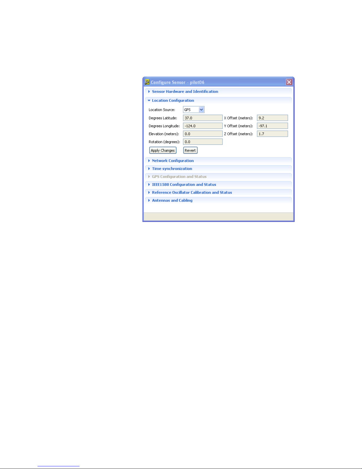
The Location Data view of the sensor configuration dialog box is used to view
and manually set the sensor's location data. Use this view when the sensor's
GPS receiver is not active, such as when a sensor is located indoors, or the
sensor location has poor GPS reception.
Page 18
16 RF Sensor User Guide
Location Source Menu
At the top of the view is the “Location source” drop-down menu. To direct the
sensor to derive its location from the GPS receiver, select the “GPS” menu
selection. To manually set the sensor's location select the “Manual” menu
selection and enter the proper values in the rest of the view's dialog boxes.
Descriptions of the values to enter are given in the following sections.
The source of the location data: Manually set, taken from GPS, or not
set.
Degrees Latitude expressed as degrees and a decimal fraction. North
is entered as a positive value; South is entered as a negative value.
Degrees Longitude expressed as degrees and a decimal fraction. East
is entered as a positive value; West is entered as a negative value.
Elevation (meters)
Y Offset (meters)
X Offset (meters)
Z Offset (meters)
Rotation (degrees)
For more information about the Location Data and the GPS system, see the
section “GPS Configuration and Status” below.
Setting Locations Indoors
For indoor applications within a single building, it’s usually easier not to work
in a latitude-longitude coordinate system. In these applications, choose a
convenient location as a reference point and define a direction (in the same
direction as walls or aisles) as the x-direction. All sensors will have the latitude
and longitude set to the same reference location, which is usually 0, 0.
Because buildings are often not oriented north-south, the SMT software allows
entry of a rotation value that describes a location’s y-axis direction relative to
true north.
Page 19
17 RF Sensor User Guide
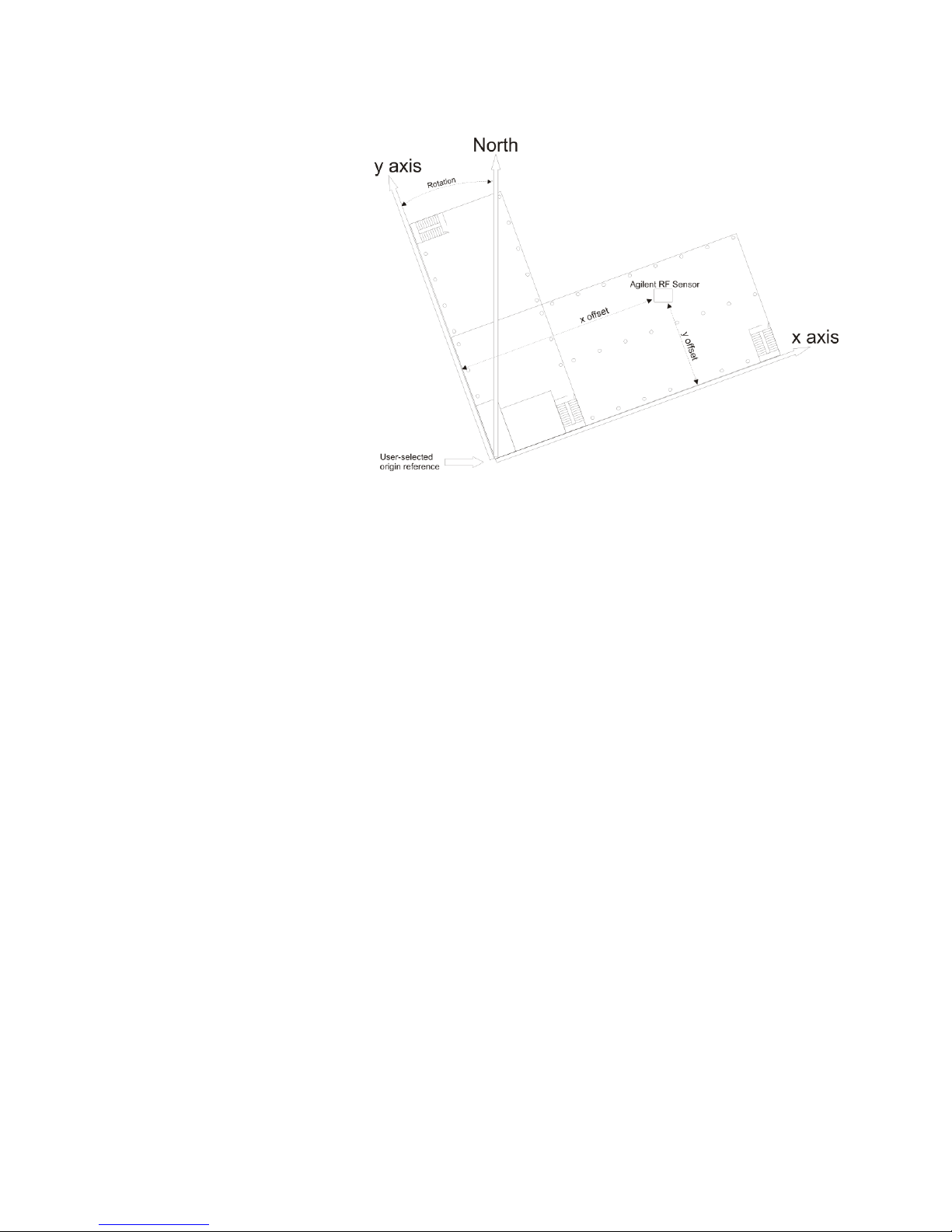
In the following illustration, the difference between north and the building’s
orientation is the rotation value. The RF receiver’s position is the offset (in
meters) from the chosen reference point.
Mixed Indoor-Outdoor Locations
For sensor networks that contain a mix of indoor and outdoor sensors, or for
applications with sensor networks spanning multiple buildings, the latitude
and longitude should be set to the correct value, and a rotation entered to
account for the difference between the defined X-Y coordinate system of a
specific building, and true North.
Note: SMT mapping does not support maps or images with rotation. If rotation
is used, the map must be oriented with North pointing up. While rotated
coordinate systems can still be used, the building would need to appear
rotated in SMT as shown in this graphic. For most indoor applications involving
one building, the orientation of the system relative to true north is probably
not important. In these cases, the rotation can be left at zero degrees, and the
building floor plan image can be oriented with Y pointing up.
Antenna Orientation
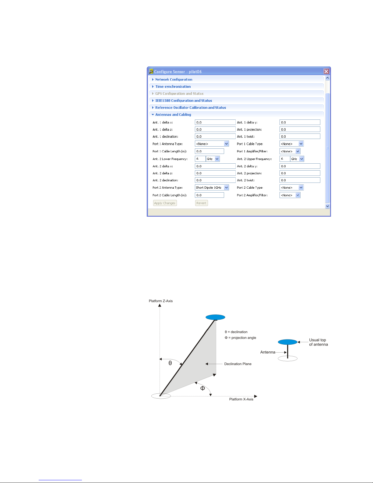
Enter the appropriate antenna orientation information in the Antennas and
Cabling (Antennas and Configuration Page) under the Configure Sensor Page.
Enter the delta x, delta y, and delta z, which describe the displacement(s) of
the antenna from the sensor. It is also possible to enter three angles that
describe antenna orientation: declination, projection, and twist.
Page 20
18 RF Sensor User Guide
In this discussion, the antenna “platform” is just the building in the indoor
scenario discussed in the previous section, (although it could be a vehicle in a
mobile deployment.) The antenna delta x, delta y, and delta z offsets in the
"Antennas and Cabling" menu refer to the platform (building) coordinates.
Declination (0-180 degrees) is the angle the antenna is tipped from the
platform vertical, 0 degrees being right-side up and 180 degrees being
upside-down.
Projection (0-360 degrees) is the angle in the antenna platform’s x-y plane
that the projection of the antenna tip makes with the platform’s front
(building’s positive x-axis). See the following figure. CCW is positive. Note that
if the declination = 0 or 180 exactly, the projection angle is arbitrary. It is
convenient to enter projection = 0 in these cases.
Page 21
19 RF Sensor User Guide
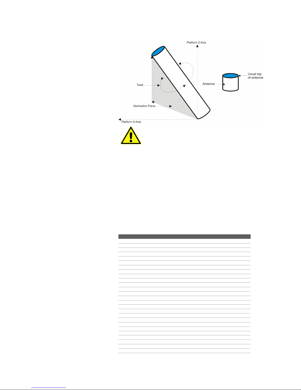
Twist is the angle that the antenna is twisted about its right-side-up axis. (See
the following figure.) Again, CCW is positive. Twist = 0 is defined as when the
front of the antenna aligns with the projection direction.
Note that if the declination angle, is equal to or nearly 180
degrees, a CCW twist is really a clockwise (CW) twisting of
the upside-down object.
Antenna Pattern Data
Pattern data for a number of antenna types are provided by Keysight in the
menu boxes Port 1(2) Antenna Type on the Antennas and Cabling (Antennas
and Configuration Page). Users may wish to use the same type of antenna on
each port (e.g., for spatial diversity, which increases the likelihood of at least
one good reception when the signal is narrowband and subject to multipath
fading) or different types of antennas (e.g., to cover different frequency bands).
If the desired antenna is not in the menu list, the user has several options. If
the deployed antenna is basically isotropic over the horizontal plane, the user
can simply pick “short dipole” as the antenna type. If the antenna is deemed
to have more complicated directional behavior, the user can enter pattern data
in the form of an Excel CSV (comma-separated values) file. The file format is
shown below:
# Insert r comment here. This is a short dipole
Freq (MHz)
Azimuth (deg)
Declination (deg)
Gain (dBi)
1000 0 0
-50
1000 0 15
-9.98
1000 0 30
-4.26
1000 0 45
-1.25
1000 0 60
0.51
1000 0 75
1.46
1000 0 90
1.76
1000 0 105
1.46
1000 0 120
0.51
1000 0 135
-1.25
1000 0 150
-4.26
1000 0 165
-9.98
1000 0 180
-50
1000
180
15
-9.98
1000
180
30
-4.26
1000
180
45
-1.25
1000
180
60
0.51
1000
180
75
1.46
1000
180
90
1.76
1000
180
105
1.46
1000
180
120
0.51
1000
180
135
-1.25
1000
180
150
-4.26
1000
180
165
-9.98
Page 22
Antenna data entry begins on line 4 of the Excel file. At least one frequency
Note: in deploying antennas in echo-filled environments such
as buildings, the actual effective pattern will depart somewhat
from the anechoic-measured pattern. Features such as the
exact depth in dB and angular position of nulls will shift in
both amplitude and direction. Thus, users should save
themselves the extra work of over-encoding very complicated
patterns. Keysight’s software smooths some of the “pattern
complexity”. If, at a given frequency, the antenna pattern has
an excessive number of lobes (say, 10 elevation lobes and ~10
deep nulls), it’s not good to trust an antenna at that frequency
for power-based geolocation.
must be given and at least two azimuths (preferably 180 apart) must be
entered for each frequency. For each frequency given (obtained from the
antenna, manufacturers provided, anechoic chamber measurement data), the
user must specify the pattern gain at a minimum of 3 declination angles: 0,
180, and some angle in between 0 and 180, usually 90 (the equatorial or
horizon plane)
Note: it is not necessary (and in fact it is redundant) to specify the gain for
every azimuth given and declination = 0 or 180.
In general, it is NOT necessary to provide the same number of declination
angles for each azimuth specified. For example, if a manufacturer specifies the
pattern in two principal planes (usually referred to as E-plane and H-plane),
then there will be two azimuths 180 apart with a collection of declination
gain data, whereas all the other azimuths will be associated with a single
declination of 90.
Depending on the amount of anisotropy in the pattern, the user may want to
specify only a few (azimuth, declination) gain entries or many. There is no limit
to the number of line entries. Also, the user can enter a number of (azimuth,
declination) entries for one frequency and a different number of entries for
another frequency – there is no constraint on matching of azimuths and
declinations.
20 RF Sensor User Guide
Once the new antenna type’s CSV file is created, import the file to be used by
SMT as follows.
1. Click Tools > Preferences > Antennas and Cabling > Antenna Types >
Add
2. Browse to the desired CSV file. A prompt will appear requesting an
antenna type name.
Page 23

Cable Attenuation Data
# Insert comment here. This is a
definition for RG-8X
Velocity
0.86
Loss Units
dB/100ft
Frequency
(MHz)
Loss
1
0.1
10
0.4
50
0.9
100
1.3
400
2.7
900
4.2
1000
4.5
2000
6.7
3000
8.6
4000
10.3
5000
11.8
6000
13.3
Cable attenuation data for a number of cable types are provided by Keysight in
the menu boxes Port 1(2) Cable Type on the Antennas and Cabling (Antennas
and Configuration Page). Select the type of cable being used for the given
sensor, and then enter the length of that cable in meters in the entry Cable
Length.
If the cable being used is not in the menu list, the user can enter the cable
data in the form of an Excel CSV file. In this file,
Line 1 is a comment describing the cable type.
Line 3 states the velocity factor (normalized to the speed of light in
vacuum).
Line 5 states the units (either dB/100ft or dB/100m).
Line 7 gives the column headings Frequency(MHz) and Loss (in Loss
Units). Data entry begins in
Line 8. Frequency values are given in Column A. Velocity factor, loss
units, and loss units values are given in Column B. An example file is
shown below:
21 RF Sensor User Guide
The lowest frequency entry should be less than or equal to 20 MHz and the
highest frequency entry should be 6000 MHz This spread of values covers the
functional range of the N6854A. Enter as many entries as are determined
important in between these top and bottom values. Linear interpolation is
used for center frequencies not on the list.
Once the CSV file is complete, Click:
Tools > Preferences > Antennas and Cabling > Cable Types > Add
Then browse to the desired CSV file. A prompt will be displayed, requesting a
cable type name that is easy to remember. Once the Add operation is
completed, the added type appears in the list of cable types in the Sensor
Configuration > Antennas and Cabling > Cable Type button of the Dashboard.
Page 24
22 RF Sensor User Guide
Amplifier / Filter Data
Some users may employ external amplifiers to compensate for weak reception
or lossy cables. Other users may employ external filters to reject strong outof-band interferers. It is possible to include the effects of these system block
components on the calibration by creating an amplifier/filter CSV file.
In this file, line 1 is a comment describing the amplifier or filter. Line 3 includes
the column headings Frequency (MHz), Gain (dB), and Delay (ns). Data entry
begins on Line 4 with frequencies in Column A, gains in Column B, and delays
in Column C. An example file is shown below:
# This is an example file for a filter/amplifier module
Frequency (MHz)
Gain (dB)
Delay (ns)
50
-10 0 6000
-10
0
The highest frequency entry should be 6000 MHz, corresponding to the upper
limit of operation of the N6854A. Linear interpolation is used for center
frequencies not in the list.
Once the CSV file is complete, Click:
Tools > Preferences > Antennas and Cabling > Amplifier/Filter Types > Add
Then browse to the desired CSV file. A prompt will request an amplifier/filter
type a name that’s easy to remember. Once the Add operation is complete,
the added type appears in the list of Amplifier/Filter types in the Sensor
Configuration > Antennas and Cabling > Amplifier/Filter Type button of the
Dashboard.
Network Configuration Data
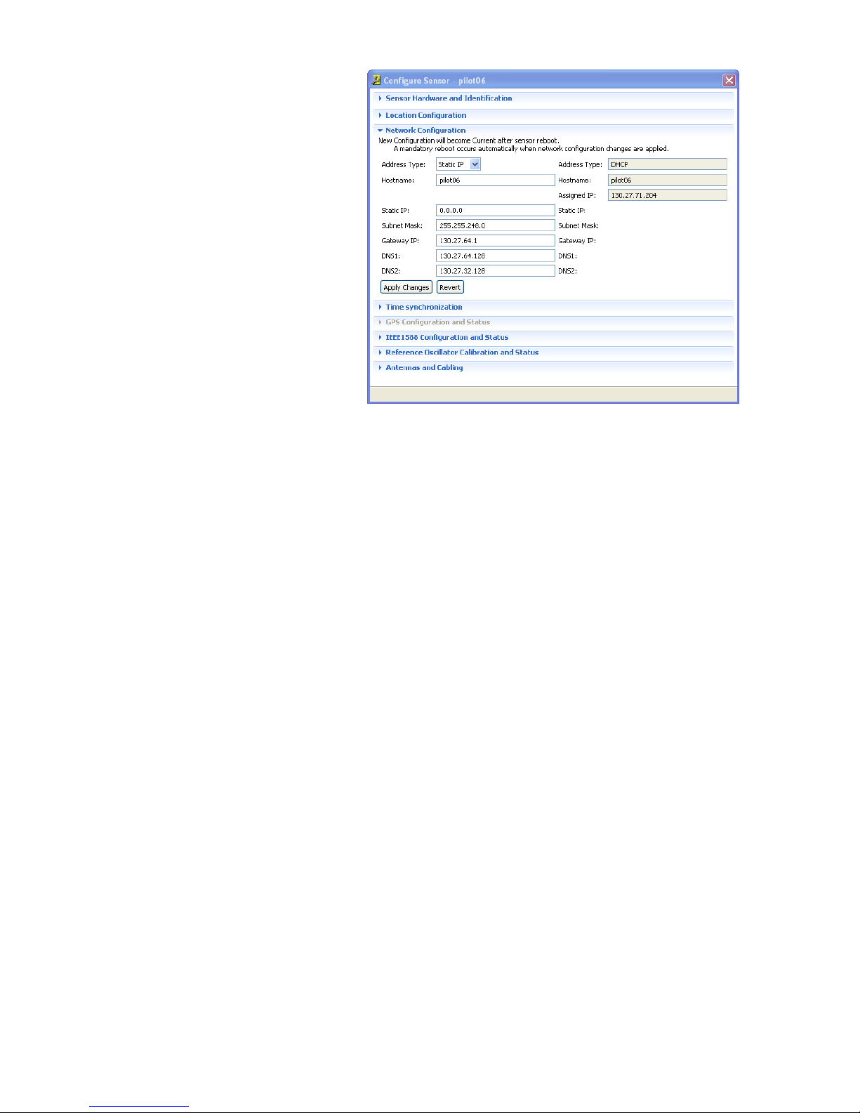
The Network Configuration Data view of the sensor configuration dialog box is
used to view and manually set the sensor's network configuration. This view
shows two sets of configuration data, a Stored Configuration and Active
Configuration. The values displayed under the Active Configuration heading
are the values currently being used by the selected sensor.
The text entry boxes displayed under the Stored Configuration heading are
used to enter new configuration values that can be applied to the sensor. The
values that are entered in the Stored Configuration text entry boxes are written
to the selected sensor via the SMS when the Apply changes button is clicked.
Page 25
23 RF Sensor User Guide
The configuration values that are entered in this view and applied to the
sensor are stored by the sensor and become active the next time the sensor
reboots. The values that can be changed in the Network Configuration Data
dialog box include:
Address Type: (Static or DHCP)
Hostname
Static IP
Subnet Mask
Gateway IP
DNS1:
DNS2:
To abandon changes made before applying them to the sensor, click on the
“Revert” button.
To write the network configuration changes to the sensor, click the “Apply
Changes” button.
GPS Configuration and Status
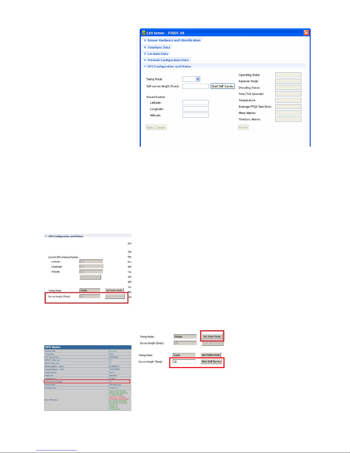
When a GPS antenna is connected to the RF Sensor, this display is used to
configure the GPS and displays the state of the RF receiver. On the left of the
display are text boxes related to the RF receiver’s GPS subsystem. On the right
of the display are shaded boxes with system status values returned from the
RF receiver.
Page 26
24 RF Sensor User Guide
The system status values displayed in the shaded boxes are listed in Appendix
A. The text boxes concerning the GPS subsystem are described in the
following sections.
Timing Mode
There are three timing modes: Static, Mobile, and Not Set.
Static mode is used for installations where the RF receiver is in a
fixed position.
Mobile mode is used when an RF receiver is installed on a vehicle
(such as an automobile or truck.)
Not Set mode specifies that the timing mode was deliberately left
unset.
Self-survey length (fixes)
The Self-survey length (fixes) text box is used to enter the number of GPS fixes
required to calculate the receiver’s location. A large value allows for a more
precise location fix, but takes much longer for the GPS to collect these fixes.
Smaller values allow for a faster (but less precise) location fix.
The self survey length is stored in the GPS module’s flash memory so it is
saved even when the module loses power.
If the SMT GUI is used to change the Timing Mode to Static Mode, the
SMT/SMS always sets the self survey length to 600 fixes. To override the
survey length, use the “Start Self Survey” button. The example below uses 20
fixes which will take approximately 20 seconds.
The GPS Status web page will display the self survey progress.
Note: The self-survey length (fixes) is initially set to a very high number and
takes a long time to complete.
Page 27
25 RF Sensor User Guide
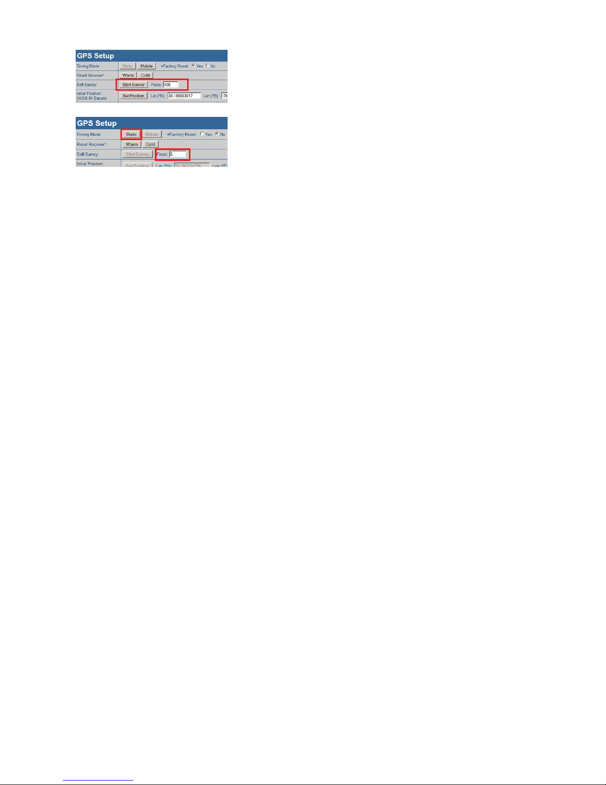
The self survey length can also be set I the GPS Setup web page. From Sensor
web home, navigate to Global Positioning and then, GPS setup. The web page
will show and initial value of 400 which is NOT the current self survey length. It
is a web page default value only. When switching to static mode within the
GPS Setup web page, the firmware uses the number of fixes in the web page.
Clicking on the Start Self-Survey button begins the GPS collecting the number
of fixes entered in the text box.
Stored Position
The three Stored Position text boxes are used to manually enter an
approximate location for the location of the RF receiver. Providing this
approximate location can help the GPS system to calculate a corrected
position more quickly. The three dialog boxes are:
Latitude—expressed as degrees and a decimal fraction. North is
entered as a positive value; south is entered as a negative value.
Longitude—expressed as degrees and a decimal fraction. East is
entered as a positive value; west is entered as a negative value.
Altitude—expressed in meters.
Page 28

26 RF Sensor User Guide
1588 Data
The 1588 Data view is used to set the PTP domain of an RF sensor and to view
the parameters of the IEEE 1588 precision time protocol. The following
parameters may be viewed or changed:
PTP Domain
This number specifies the domain to which the
current sensor belongs. This is the only
parameter that can be changed by the user.
PTP Time
This is the time of the RF sensor’s local clock.
This display value is seconds since the
beginning of the current epoch.
Local MAC Address
This is the MAC address of the RF sensor being
configured.
Master MAC Address
Each domain has one Master Clock. This value
is the MAC address of the Master for this
sensor’s domain.
Grand Master MAC
Address
Each domain has one Grand Master Clock. This
value is the MAC address of the Grand Master.
Master IP Address
This value is the IP address of the domain’s
Master Clock.
Clock Offset (sec)
This value is the calculated offset of the RF
sensor’s local clock from the Master Clock.
Variance (sec^2)
This is a measure of the inherent precision of
this sensor’s local clock. This value is used to
order clocks into Master/Slave relationships.
State
This shows the current Master/Slave state of
the current RF sensor.
Slave Only?
This shows whether the sensor can be only a
Slave.
To update the PTP Domain value, click the Apply Changes button. If a new
domain value is entered and that value is not wanted, click the Revert button.
Reference Oscillator
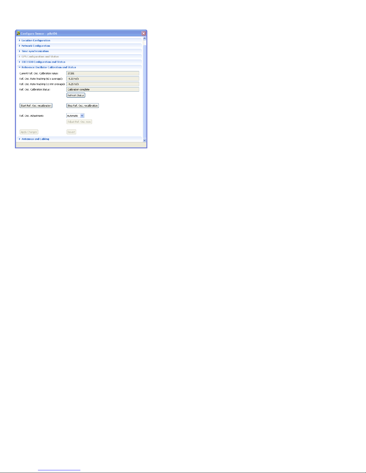
The N6841A has an ovenized reference oscillator. A digital to analog
converter (DAC) is used to adjust the reference oscillator to match the time
synchronization source (GPS or IEEE-1588). This adjustment runs in the
background very infrequently and can be turned off using the Configure
Sensor pane. It is recommended to leave the reference adjustments in the
Automatic mode.
Page 29
27 RF Sensor User Guide
The fields on this pane are as described below:
Current Reference Oscillator Calibration Value is the DAC value that
is currently being used. This number will change each time an “Adjust
LO” operation completes.
The Oscillator Rate Tracking (60 s average) indicates the difference in
the local reference compared to the time-sync source (e.g. GPS,
remote 1588 master, etc). The time synchronization servo
compensates for this difference. This is a 60 second running average
which is update once per second.
For proper reference oscillator operation, reference oscillator rate
tracking (60 seconds average and 10-minute average) entries should
be <±10ns/sec. For entries >±10ns/sec, let the sensor warm up for 30
minutes or, do a reference oscillator recalibration.
The 10 min average is the same as above but is a ten-minute running
average.
The reference oscillator can have a Calibration Status of:
“Calibrating” or “Complete.”
The above fields can be refreshed using Refresh Status.
Start Reference Oscillator recalibration button is for expert users only
under guidance from Keysight support. It manipulates the DAC to
generate a calibration curve. The sensor MUST be synchronized to
the external time sync source.
Stop Reference Oscillator recalibration will abort the above
calibration operation.
The Reference Oscillator Adjustment can be “Manual” or
“Automatic”. It is recommended to leave the sensor in the
“Automatic” mode.
When an Adjust Ref. Osc. now operation occurs, the calibration
equation and the 10-minute average are used to compute a new
calibration value. The computed value is stored in the HW and is
persisted. If/When the sensor reboots, the last calibration value is
read from the persistent storage and loaded back into the HW. If the
sensor is in “Manual” oscillator adjustment mode, a “reference
Oscillator calibration needed” may be displayed. If this is the case,
navigate to this panel and manually initiate a recalibration of the
reference oscillator.
In “Manual” mode, click the “Adjust L.O. now” button to cause the
adjustment. In Automatic mode, the sensor will do this operation
every 10 minutes. If a measurement is in progress, it will be deferred
until the measurement completes.
Apply changes button applies the selected changes.
The Revert button brings the sensor back to the state prior to the last
Apply changes.
Page 30
28 RF Sensor User Guide
Embedded Apps (beta)
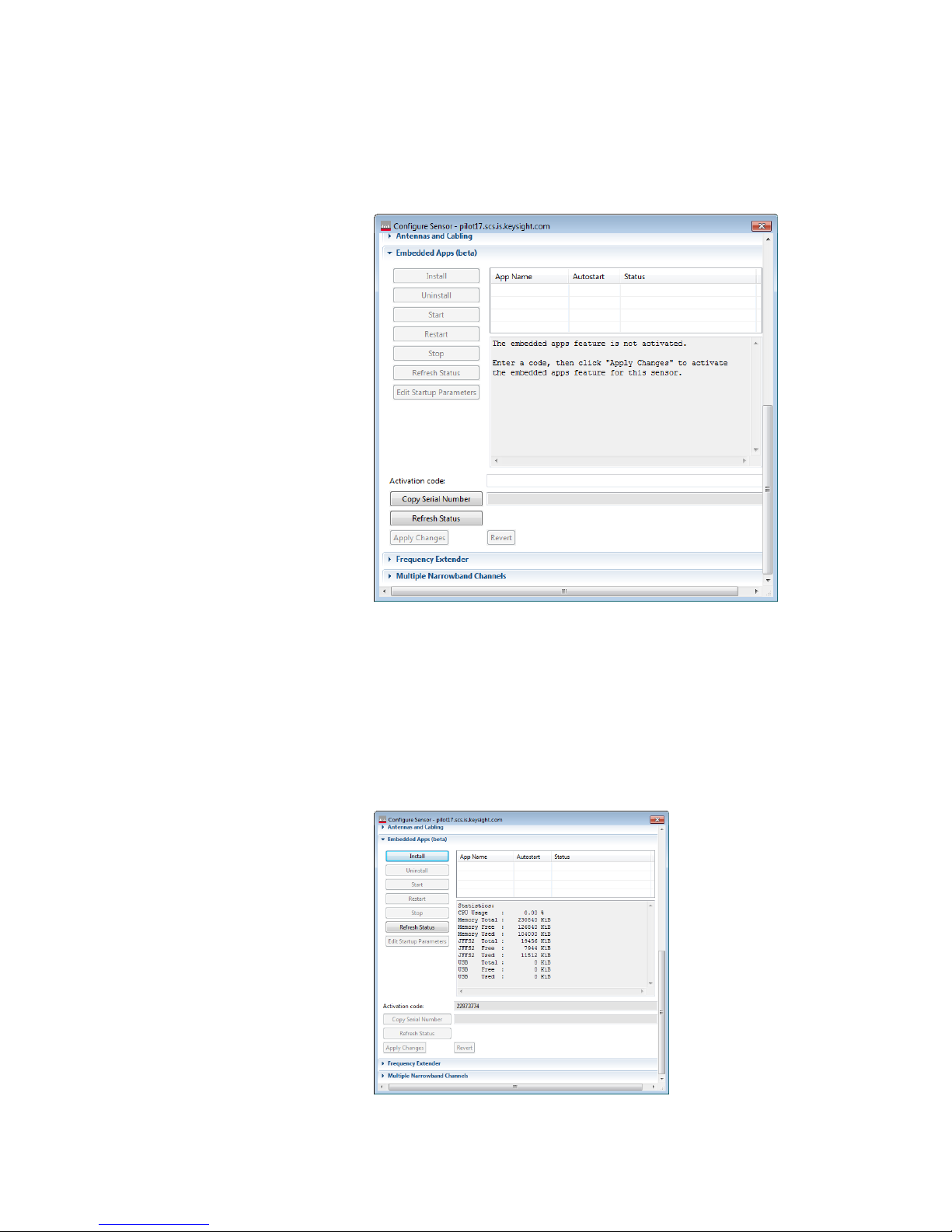
Embedded Apps are a means of running applications on the processor inside
the RF Sensor. Since the processor inside the sensor runs Linux, the app uses
the Linux version of the Sensor Access Library (SAL) to communicate with the
sensor. The app can connect to a sensor, search, get IQ data, and store
information on a USB stick in the sensor (available in late 2015).
To be able to utilize the Embedded App infrastructure, the user must activate
the feature by entering in an Activation Code. The Activation Code is a
purchased item known as N6841A-EFP (available late 2015 or early 2016). Hit
Copy Serial Number to copy the serial number to the clipboard, then paste it
into the Keysight Software Manager using the N6841A-EFP entitlement
certificate to redeem an activation code.
Once the code is entered and “Apply Changes” is hit, then if the code is
correct, then options to “Install” a new app and the memory usage of the
sensor are displayed.
Page 31
29 RF Sensor User Guide
To compile an embedded app, use the API in C:\Program Files
(x86)\Keysight\RFSensor\SALLinux. The documentation called SAL Reference
applies for LINUX.
The final executable must be tar’d and gzip’ed.
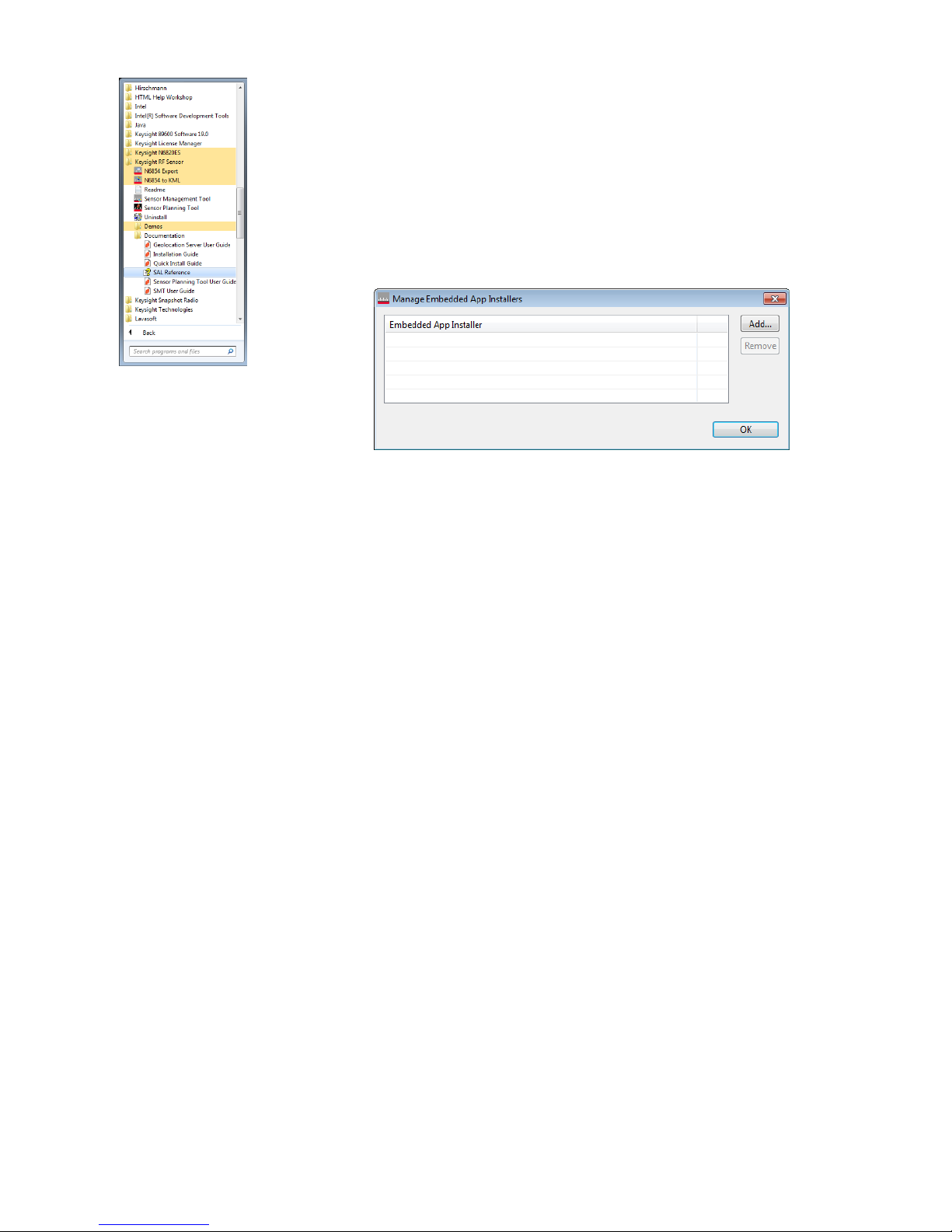
To install an embedded App:
First add the embedded App installer
In Sensor Management Tool, go to Tools->Manage Embedded App
Installers
Press the Add button to add an installer.
Once the embedded App installer is added, go back to the Configure Sensor
menu and click Install.
To run embedded app automatically when the sensor is powered on, press
“Edit Start-up Parameters”.
Frequency Extender
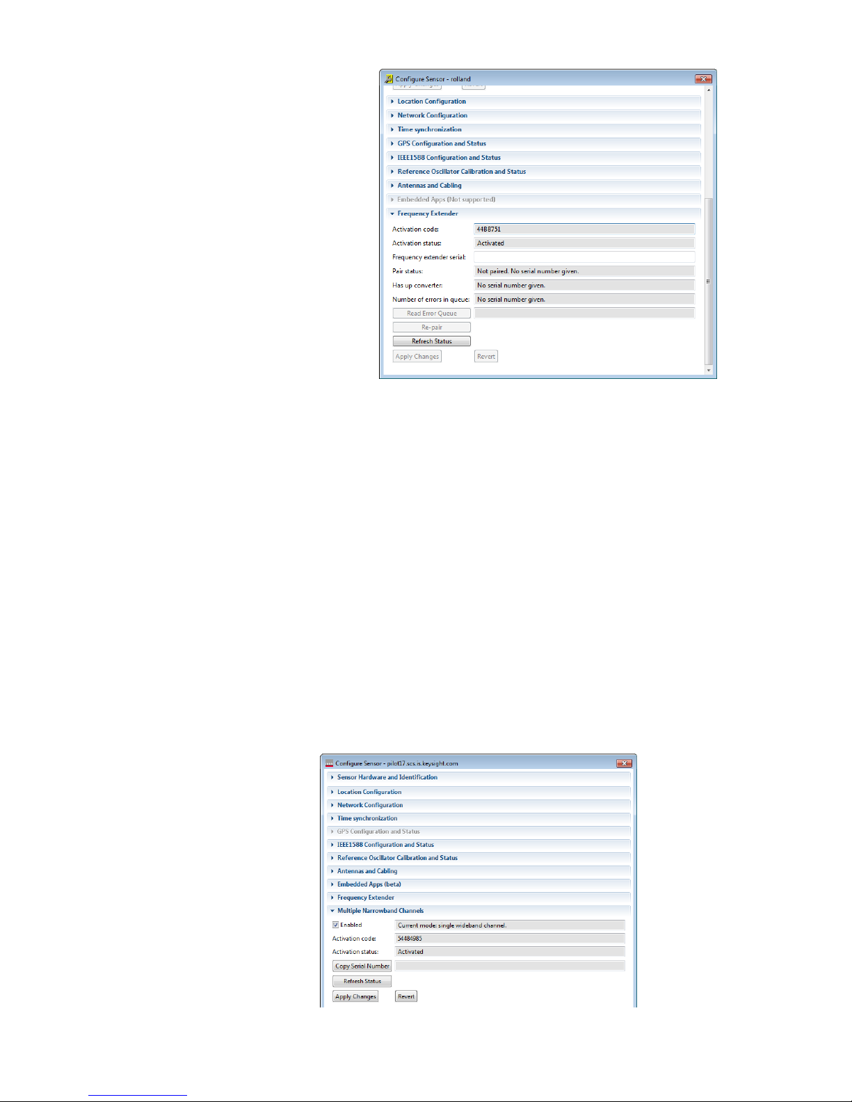
A 3rd party Frequency Extender can be purchased to use with the RF Sensor.
The size, weight and look are very similar to the RF Sensor. The frequency
extender extends operation to 100 kHz – 27.4 GHz. Control of the Freq
Extender is done by Ethernet (same network). The Antenna connects to the RF
in of the freq extender, and IF Out of the Freq Ext connects to the RF In 1 of
the sensor. Configuration of the Freq Extender is done by the Configure
Sensor menu, Freq Extender tab. Enter in the Activation Code (which is per
sensor) as given at the time of order fulfilment and click Apply Changes. Once
the Activation Code is successfully entered and the Activation Status is
“Activated”, connect to any Freq Extender. Enter the serial number of the
frequency extender that is physically connected to the sensor, and Click Apply
Changes.
Page 32
30 RF Sensor User Guide
Multiple Narrowband Channels
Multiple Narrowband Channels turn a N6841A RF Sensor into an 8-narrowband
channel device. The total instantaneous bandwidth remains 20 MHz, but within
the 20 MHz, 8 channels of IQ data can be extracted simultaneously. Without
this feature, the RF Sensor is limited to 1 channel of wideband (20 MHz) IQ data.
To utilize the Multiple Narrowband Channels feature (including the SAL API
interface for it), the user must activate the feature by entering in an Activation
Code. The Activation Code is a purchased item known as N6841A-MFP Hit
Copy Serial Number to copy the serial number to the clipboard, then paste it
into the Keysight Software Manager using the N6841A-MFP entitlement
certificate to redeem an activation code. Once enabled, the Activation status
says “Activated”.
There are two modes for the RF Sensor:
1. 1 channel 20 MHz wideband IQ and FFT search;
2. if activated, the 8 narrowband channels (within 20 MHz Bandwidth)
and FFT search.
To switch modes to the narrow band channels, check the “Enabled” box and
hit “Apply Changes”.
Page 33
31 RF Sensor User Guide
Running the RF
Sensor’s Self-Test
Since the Keysight RF Sensor has no external switches, lights, or other
indicators, the SMT can provide diagnostic and self-test methods for verifying
sensor communication and operation. These are functions are available
through the Sensor’s pop-up menu and the Tools menu.
To use the diagnostic tools through the Tools menu, click:
Tools>Sensor>Diagnostic/Self-Test.
To use the diagnostic tools through the sensor pop-up menu, click
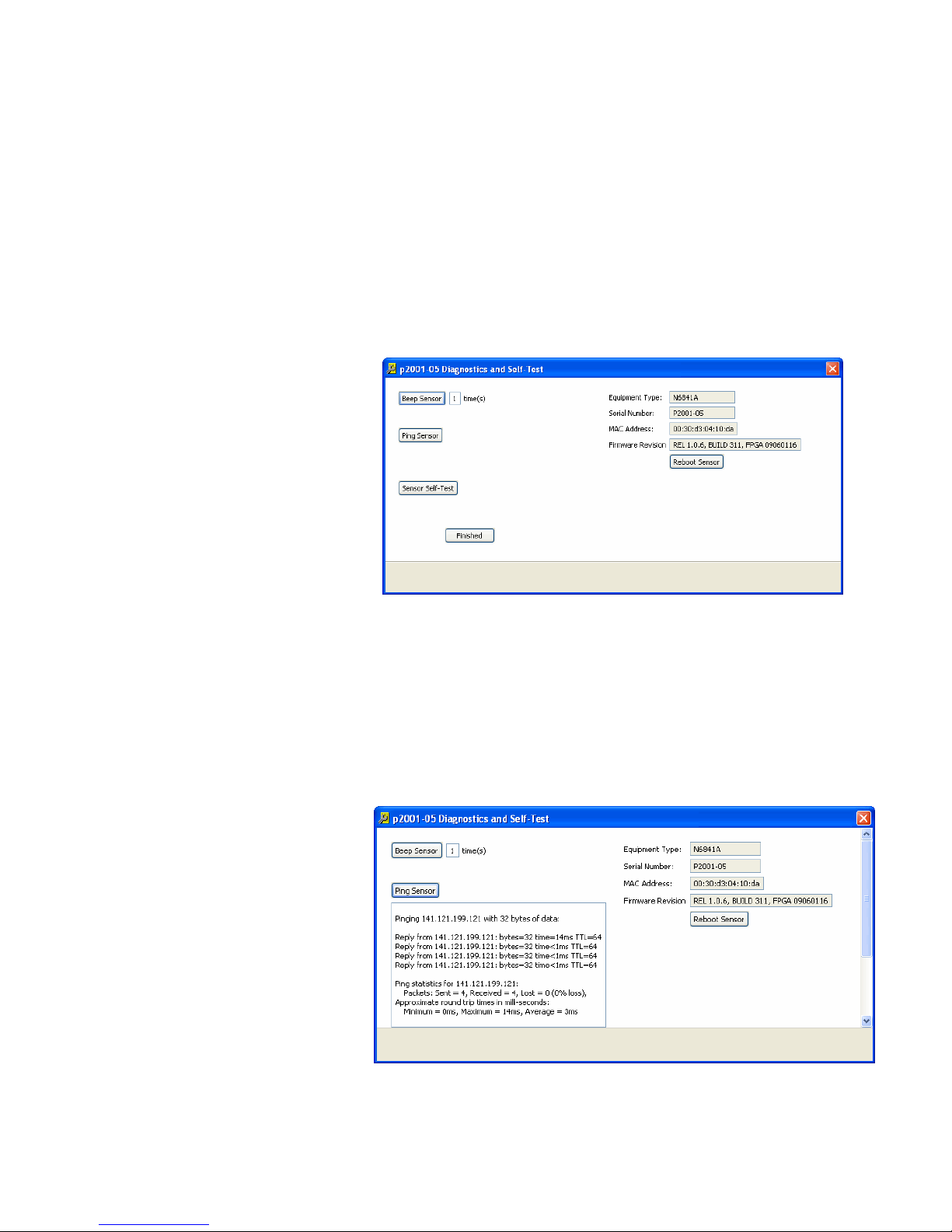
Diagnostic/Self-Test. SMT displays the following dialog box.
Beep Sensor
Clicking this button provides a quick way to verify that the SMT and sensor are
communicating, and that the sensor has power and is not hung. Enter the
number of times the sensor should beep in the text box, then click the Beep
Sensor button.
Ping Sensor
Clicking this button sends an “echo request” packet to the sensor and displays
the results of the operation.
Page 34

32 RF Sensor User Guide
Sensor Self-test
Clicking this button causes the sensor to perform the same self-diagnostics as
when power is applied to it. In both cases, the sensor performs a quick test of
some of its major functions.
At power-up, if the sensor fails one of these self-tests, it emits a set of audible
beeps, indicating which test the sensor failed. When the Diagnostics/Self-test
is run from SMT, all four tests are run; but beeps DO NOT occur if there is a
failure.
Sensor self tests include:
PCI test—If the sensor fails this test, it emits one long beep.
Capture SDRAM test—This test performs a quick write/read test of the
sensor’s capture SDRAM. If the sensor fails this test, it emits two long
beeps.
Signal Path test—This test performs an internal analog test signal to
verify most of the analog signal path. If this test fails, the sensor will
emit three long beeps.
LO Unlock test—This test verifies that all the LO oscillators can sweep
through their tuning ranges without unlock. If the sensor fails this test,
the sensor emits four long beeps.
Reboot Sensor
Clicking the Reboot Sensor button reboots the sensor, requiring the sensor to
complete its power-on self test.
Page 35
33 RF Sensor User Guide
Configuring the
Map
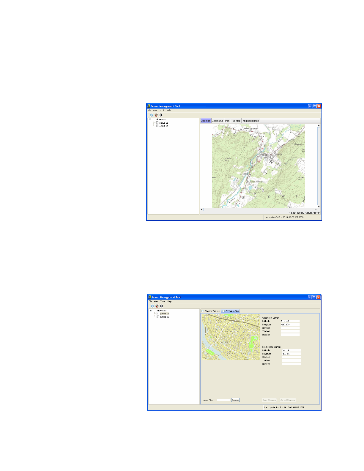
SMT can display the locations of sensors on a map. Display the map either by
clicking the map icon on the toolbar, or by clicking the menu selection: View >
Map. When the map image is correctly correlated with the location data, the
SMT displays the location of the RF sensors in its subnet on the map. The map
location pointed to by the mouse pointer is displayed in the lower right-hand
corner of the map window.
Configure the map using the Map Configuration window. Display the Map
Configuration window either by clicking the configuration icon on the toolbar,
or by clicking on the menu selection View > Configuration, then by clicking the
Configure Map tab at the top of the right-hand side of the window.
Note: When changes are made to the Map Configuration page, the changes
are not saved until the “Save Changes” button is clicked. To discard the
unsaved changes, click the “Cancel Changes” button. SMT currently reads the
map image only at start time. If the map image is changed, exit and restart the
SMT for an updated image to use.
Page 36

34 RF Sensor User Guide
The Map Configuration window displays the currently used map and, to its
right, a set of text boxes that are used to define where the map boundaries are
located. The text boxes are used to specify the following values for the upperright and lower-left corners of the map:
Latitude—expressed as degrees and a decimal fraction. North is
entered as a positive value; south is entered as a negative value.
Longitude—expressed as degrees and a decimal fraction. East is
entered as a positive value; west is entered as a negative value.
Elevation—expressed as meters, this is the altitude of the selected
corner of the map.
Y Offset—expressed as meters, this is any Y-axis offset of the selected
corner of the map.
X Offset—expressed as meters, this is any X-axis offset of the selected
corner of the map.
Rotation—expressed as degrees, this is the map’s deviation from true.
(The map displayed is assumed to be oriented with north as up.)
Selecting the Map Image
SMT displays a map image file. This map image can be one of the following file
types:
Graphics Interchange Format (.gif)
Joint Photographic Experts Group (.jpg)
Bitmap (.bmp)
Portable Network Graphics (.png)
To select an image file, enter the file name in the Image File text box at the
bottom of the Map Configuration window. Or, click on the Browse button and
browse for the file using the Windows file menu dialog box.
Note: Image files that are too large (greater than 100kb) can cause the SMT to
exhibit anomalous behaviours.
After entering the file name for the map image, the map image appears in the
Map Configuration window. The Save Changes and Cancel Changes buttons
are unavailable. Enter the location information in the Latitude and Longitude
text boxes before saving the new map image.
Page 37
35 RF Sensor User Guide
Managing Sensor
Firmware
The SMT is able to maintain the firmware of Keysight RF Sensors. With the
SMT it is possible to manage firmware versions on the PC, upload those
versions of firmware to the connected RF Sensors, and reboot the RF Sensor.
These actions are described in the following sections.
Firmware Versions
Firmware can be distributed on CD-ROM, DVD, or using the Internet.
However, the firmware is distributed, it will be a file on the hard drive of the PC
that runs SMT. This file will be compressed with a filename that contains the
firmware’s build number.
Managing Firmware Versions
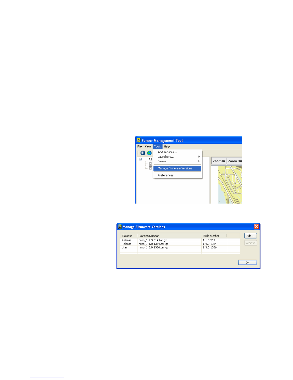
Before SMT can use a firmware file, it must know where that file is. To add a
firmware file to the SMT’s list of firmware versions, use the following steps:
1. From the SMT menus, click Tools>Manage Firmware Versions…
2. See that the SMT displays the Manage Firmware Versions dialog box.
This dialog box shows the release or user for each firmware version.
3. Click the Add button and browse to the firmware file to add. The
filename is added to the Firmware Versions List.
Page 38
36 RF Sensor User Guide
Updating an RF Sensor’s Firmware
This section describes the method for updating an RF sensor’s firmware.
Updating a sensor’s firmware is a delicate operation that,
once started, cannot be paused, halted or interrupted.
Before updating a sensor’s firmware, make sure that the
sensor has a stable power supply and that the connection
between the sensor and the PC running SMT is
undisturbed.
SMT updates an RF sensor’s firmware by uncompressing a firmware update
file and loading the uncompressed firmware on the sensor’s internal memory.
If this process is interrupted while the write operation to the RF sensor’s
internal memory is incomplete, the RF sensor will become unresponsive and
must be returned to the factory to have its memory reset and rewritten.
To update an RF sensor’s firmware, use the following steps:
1. From the SMT configuration window, click the Discover Sensors tab.
2. Click and highlight the sensor to update.
3. Click the Add to SMS button.
4. Click the dashboard icon to display the status of the RF sensor.
When the sensor’s icon in the All Sensors list displays green, the sensor is
communicating correctly and its firmware can be updated.
1. When the sensor’s icon appears green in the SMT’s dashboard, right-
click the sensor’s icon.
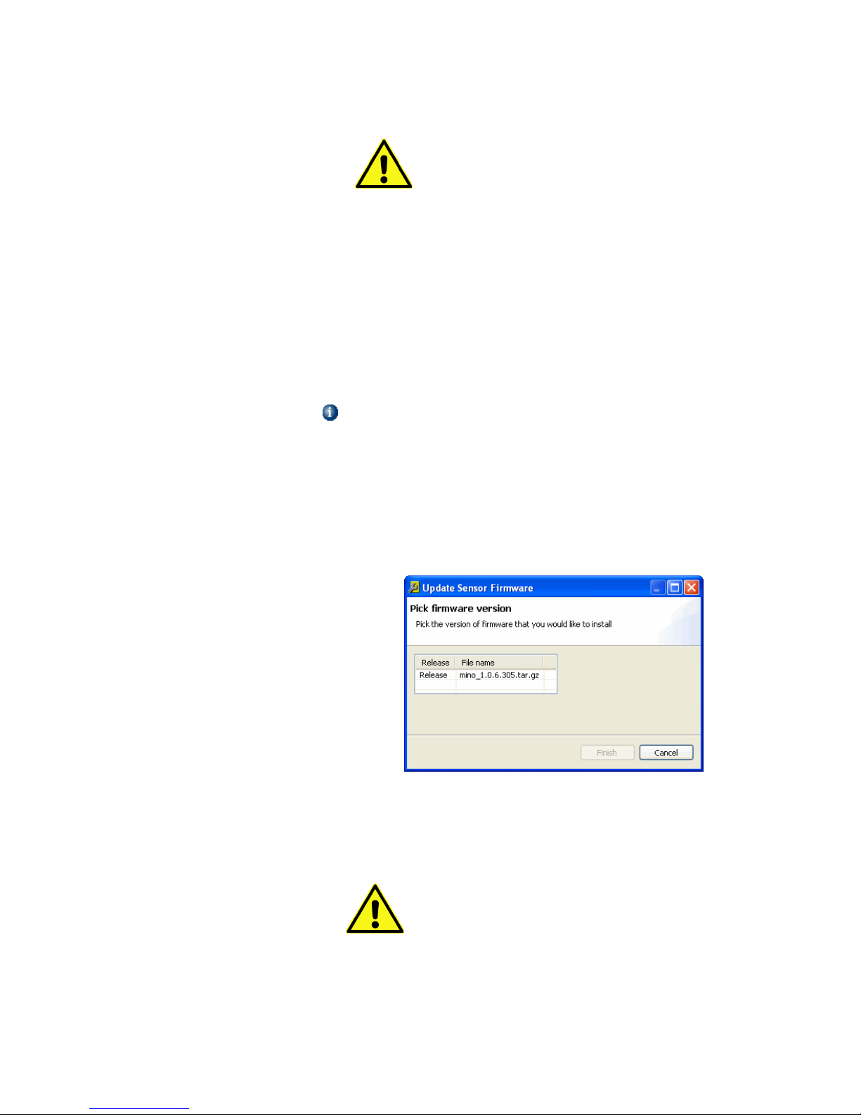
2. From the sensor’s pop-up menu, click Update Firmware… See that
the SMT displays the Update Sensor Firmware dialog box.
3. Click on the filename release version entry to upload to the RF
sensor.
4. Click Finish to begin updating the RF sensor’s firmware. See that the
sensor’s Status entry in the Dashboard list changes to Updating
Firmware.
Updating a sensor’s firmware takes a relatively long time.
Once the sensor’s firmware begins to update, do not attempt
pause, halt or interrupt the process.
Page 39
37 RF Sensor User Guide
Using the
Spectrum Monitor
If Microsoft Windows changes focus (if another program
window is placed on top of the SMT window) before the
Finish button is clicked, it is possible to lose track of the
dialog box and SMT can appear to be hung. This is normal
Windows behavior. If this happens, minimize all open
windows and maximize the SMT window to restore the dialog
box.
5. When the updating process is complete, the sensor’s Status entry in
the Dashboard list changes to Current Status.
The firmware of the RF sensor is now updated.
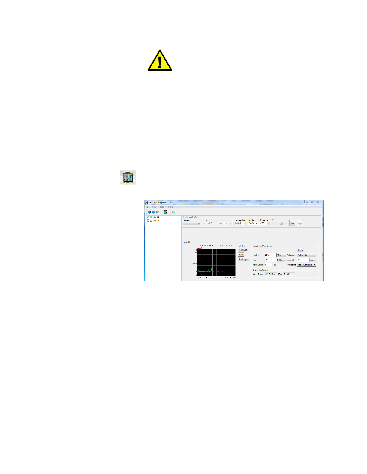
Once sensors are added to SMS, use the Spectrum monitor tool by clicking on
the Spectrum Monitor Icon in the dashboard. Select a sensor by clicking on
the check box next to the sensor name. The software displays a spectrum
monitor for the sensor. To the right of the spectrum display are the Spectrum
Monitoring controls.
The Spectrum Monitoring controls are used to specify the following:
Center— center frequency of the spectrum to monitor
Span— frequency span to monitor
Antenna— for the RF sensor to use
Interval—The rate at which the spectrum display is updated. (The
update rate can be reduced to minimize the data traffic on slow
networks.)
The spectra displayed are peak held, to show the signal content that occurs,
including burst signals. The red marker can be controlled using a mouse, or
using the “Peak”, “Peak Left”, and “Peak Right” buttons.
Page 40
38 RF Sensor User Guide
Using the Radio
Receiver
Launching an
Application from
Within SMT
To monitor an AM or FM radio transmitter, select one of the sensors whose
spectrum is being monitored using the Sensor drop-down box on the Radio
Application pane, just above the spectra.
The selected sensor must be tuned to a region in the spectrum containing the
frequency of interest; because it is not possible to demodulate a signal that is
outside the sensor’s currently monitored range.
Click Start to activate the Radio Receiver.
Enter the center frequency in the Frequency text box.
Select the modulation type (AM, FM, or FM-W {for wide band FM}) in
the Mode drop-down box.
The selected radio signal is played through the PCs sound system. Control the
volume level by using the volume slider. If the signal is not heard through the
PC sound system, make sure the PC sound is turned on. (If headphones
plugged in, there will not be sound generated from the PC’s speakers).
Stop and Start the radio receiver if a new frequency is entered.
The SMT is required for the initial configuration and management of sensors,
but is otherwise optional. For example, the SMT is not required to launch
sensor applications. While optional, the SMT provides some convenience
during normal day-to-day use of the sensors in a sensor network.
For example, the SMT can simplify the launching of selected applications on
one or more selected sensors. Using the SMT, active sensors can be identified
from a map display and multiple sensors can be tasked to run applications
using a right click of the mouse.
The SMT also provides a consistent way to launch a variety of applications,
whether developed by the user, from Keysight, or from a third-party vendor.
Programs written using the Keysight Sensor Access Library
(SAL) request sensor names from SMS. If a program is
executing on a PC in a different subdomain than the
subdomain on which the instance of SMS is running, the
program can have problem finding the needed sensor.
To avoid this problem, use the Tools > Add Sensor
procedure in SMT to add sensors either with their numeric
IP address, or by their full name (sensor name concatenated
with the domain).
Page 41
39 RF Sensor User Guide
Adding a Program to the Launch Menu
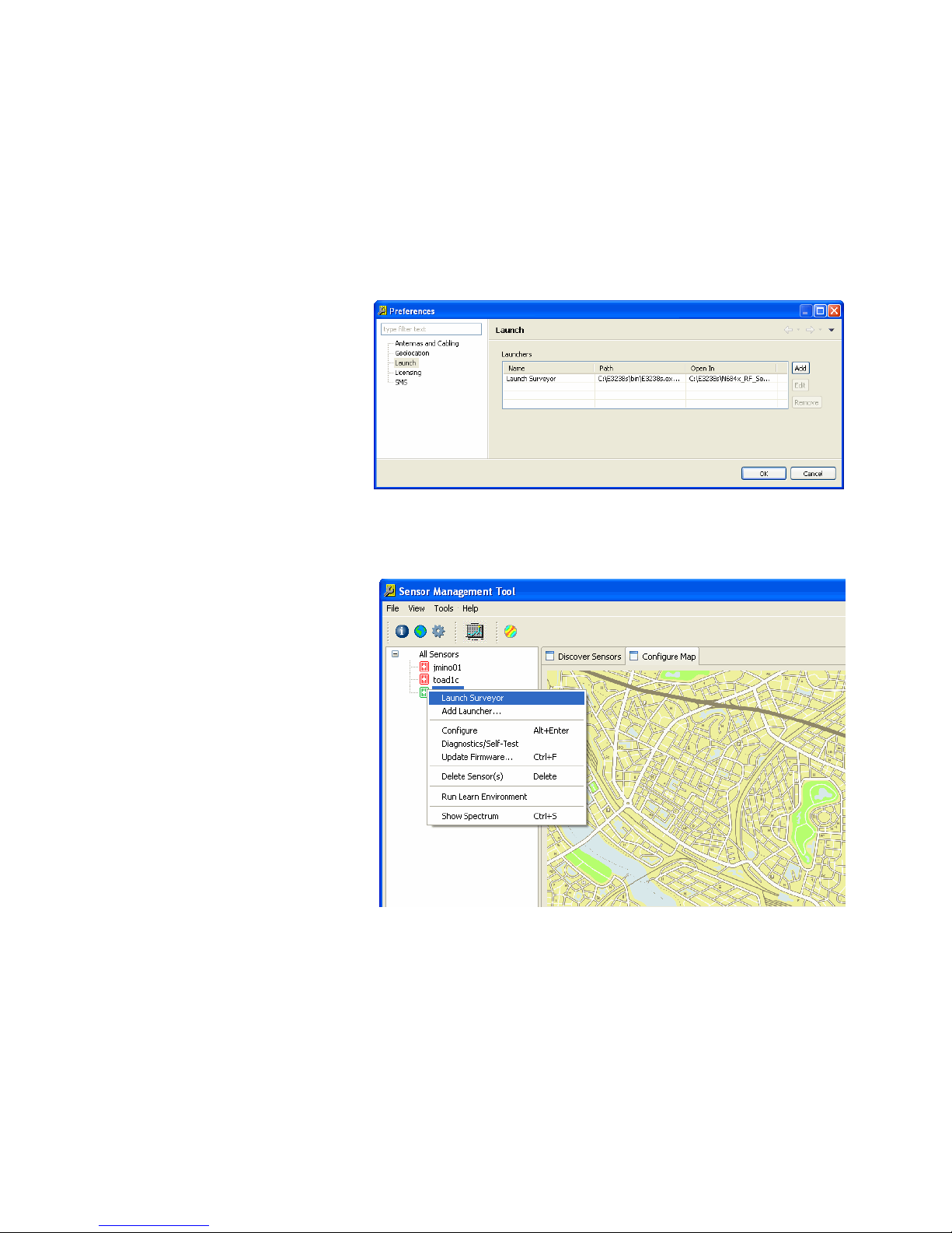
To make a sensor program available for launch using the SMT, it must be
entered in the Launch list. The Launch List is located on the Preferences
window of the SMT. There are two ways to view the Launch list: through the
menu bar or by right clicking a sensor icon.
To view the Launch list from the menu bar:
1. Click on the Tools menu.
2. Click on the Preferences menu entry.
3. On the left side if the Preferences screen, click on Launch.
To view the launch menu from a sensor icon:
1. From the active list of sensors, right click on a green (active) sensor
icon.
2. From the pop-up menu, click to launch an application that is
available in the launch list, or add an application to the list by
clicking “Add Launcher...”
Adding a Program to the Launcher List
The list of programs available to launch on the sensors is located on the
Launch view of the Preference dialog box. Entries to the launch list can be
added, edited and removed using the buttons to the right of the list.
Page 42
40 RF Sensor User Guide
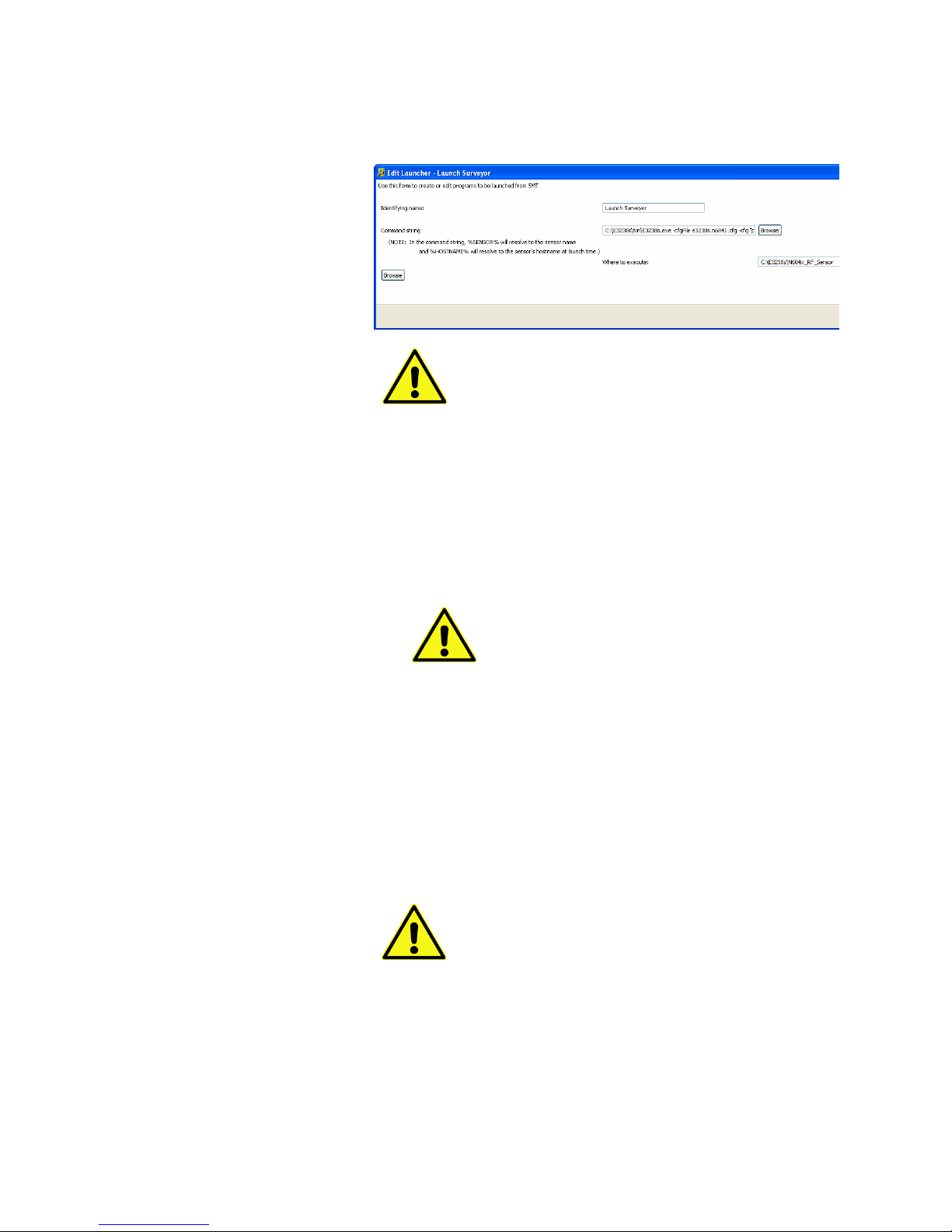
To add a program to the list of launchers:
1. Click on the “Add” button. The SMT displays the Add Launcher dialog
box. The following illustration shows a command string that will
launch Surveyor 4D.
Note: When entering the following information, do not use
the “Enter” key. This may cause typed information to be lost.
Use the Tab key (or the mouse) to advance to the next field.
2. Enter a name for the program in the “Human-readable name for this
command:” text entry box.
3. Enter a command string to the program, including command line
switches in the “Command string” text box. Note that [spaces] in the
directory or filename should be avoided. To specify C:\Program Files
(x86)\... use “C:\Progra~2\...”. According to Microsoft’s convention,
filenames or directories with spaces should be specified by the first 6
characters and end with “~2”.
Note: The variable %SENSOR% is used in the
command line. The SMT program replaces this
variable with the name of the sensor when the
program is launched. If a sensor name containing
spaces has been assigned (for example, “South
Sensor”) enclose the variable in quotation marks (so,
“%SENSOR%”).
4. Enter the directory where this command should be executed in the
bottom text entry box.
5. Click the “Save” button to save the entry.
6. Click the “Close” button to close the window.
Editing an Entry in the Launcher List
To edit an entry in the list of launchers from the Preferences dialog box:
1. Click on the “Edit” button. The SMT displays the Edit Launcher dialog
box.
Note: When entering the following information, do not use
the “Enter” key. This may cause typed information to be lost.
Use the Tab key (or the mouse) to advance to the next field.
2. If desired, edit a name for the program in the “Identifying name for
this command:” text entry box.
Page 43

41 RF Sensor User Guide
3. If desired, edit the command string to the program, including
command line switches in the “Command string” text box. To specify
C:\Program Files (x86)\... use “C:\Progra~2\...”. According to
Microsoft’s convention, filenames or directories with spaces should
be specified by the first 6 characters and end with “~2”. Note that
the variable “%SENSOR% is used in the command line. The launcher
replaces this variable with the name of the sensor when the program
is launched.
4. If desired, edit the directory where this command should be executed
in the bottom text entry box.
5. Click the “OK” button to save the entry.
6. Click the “Close” button to close the window.
Launcher List Entries for the Demonstration Programs
The RF Sensor software includes several demonstration programs. Here are
the programs and how they can be used when creating a launcher:
Identifying Name: Block
Command String:
C:\Progra~2\Keysight\RFSensor\SAL\Demo\Block\bin\Release\Block.exe -h
%SENSOR%
Where to Execute:
C:\Progra~2\Keysight\RFSensor\SAL\Demo\Block\bin\Release
Identifying Name: Stream
Command String:
C:\Progra~2\Keysight\RFSensor\SAL\Demo\Stream\bin\Release\Stream.exe
-h %SENSOR%
Where to Execute:
C:\Progra~2\Keysight\RFSensor\SAL\Demo\Stream\bin\Release
Identifying Name: FFT
Command String:
C:\Progra~2\Keysight\RFSensor\SAL\Demo\Fft\bin\Release\Fft.exe -h
%SENSOR%
Where to Execute:
C:\Progra~2\Keysight\RFSensor\SAL\Demo\Fft\bin\Release
Identifying Name: Location
Command String:
C:\Progra~2\Keysight\RFSensor\SAL\Demo\Location\bin\Release\Location.e
xe -h %SENSOR%
Where to Execute:
C:\Progra~2\Keysight\RFSensor\SAL\Demo\Location\bin\Release
Page 44
42 RF Sensor User Guide
Troubleshooting
Guide
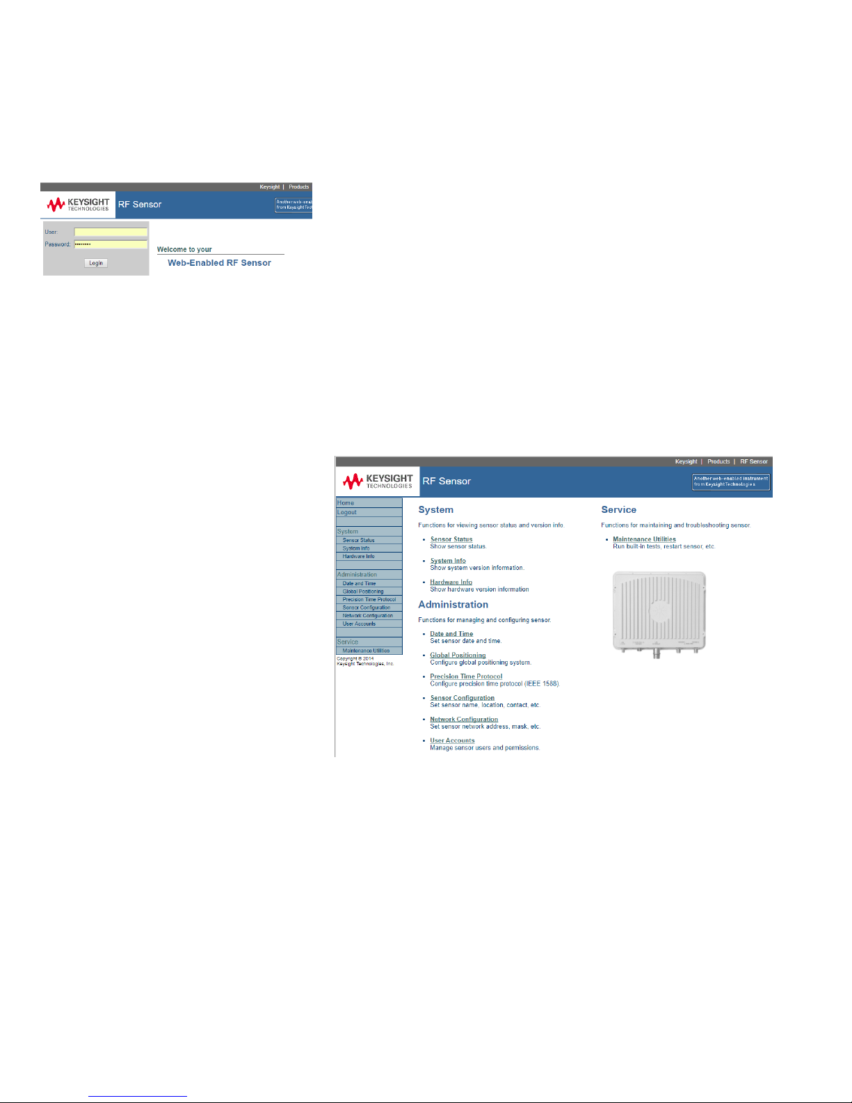
Once the RF Sensor is set up, the N6841A RF Sensor web interface can be
used to view and verify the sensor parameters, which can be helpful when
troubleshooting a sensor issue.
To access the RF Sensor web interface, open a web browser and type in the
RF Sensor name or IP address. From the Keysight factory, RF sensors are
named with K-N6841A-##### (last 5 digits of the sensor serial number).
User: guest
Password: rfsensor
Key information that can be found in the RF Sensor web interface include:
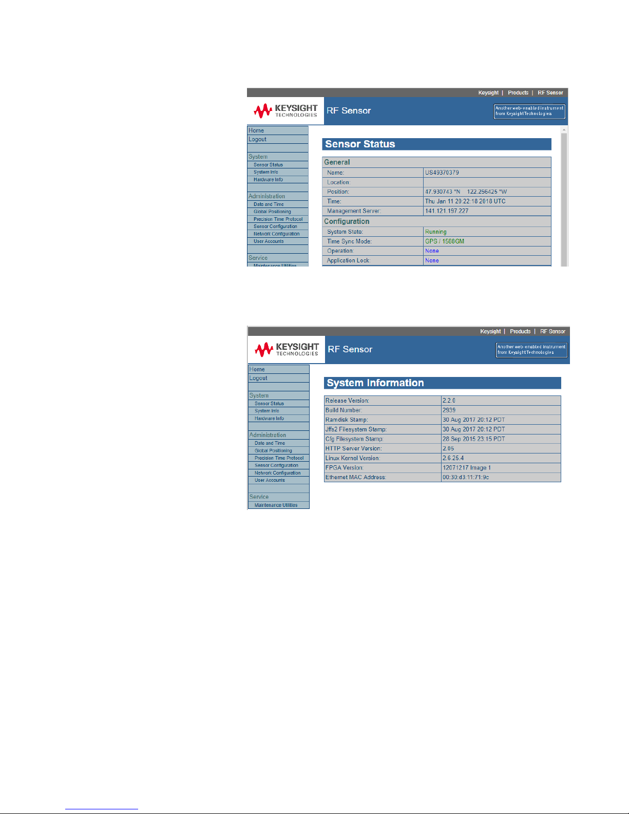
Sensor Status
System Info
Hardware Info
Global Positioning
o GPS Status
o GPS Satellites
The information provided by the web interface is a high-level indication of the
RF sensor’s health. Green, or blue text indicates that the sensor is running
properly. Red text can indicate a problem or indicated that more time is
required to stabilize. Not all panes provide user access.
Page 45
43 RF Sensor User Guide
Sensor Status
Sensor Status includes details for configuration, conditions (time, temperature,
etc), GPS time, and PTP time.
System Information
System information includes software versions and time stamp for all sensor
software components.
Page 46
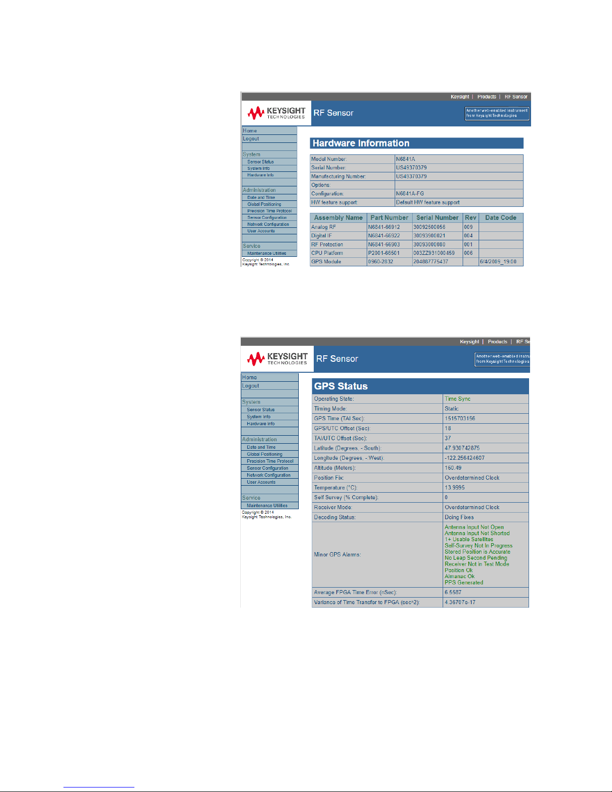
44 RF Sensor User Guide
Hardware Information
Hardware Information includes Serial and Part numbers for all sensor
hardware components.
GPS Status
Shows the overall stats of the GPS receiver inside the sensor. It includes
location and timing accuracy information. Green, or blue text indicates that
the sensor is running properly. Red text would indicate that more time is
required to stabilize or there is an issue.
Page 47
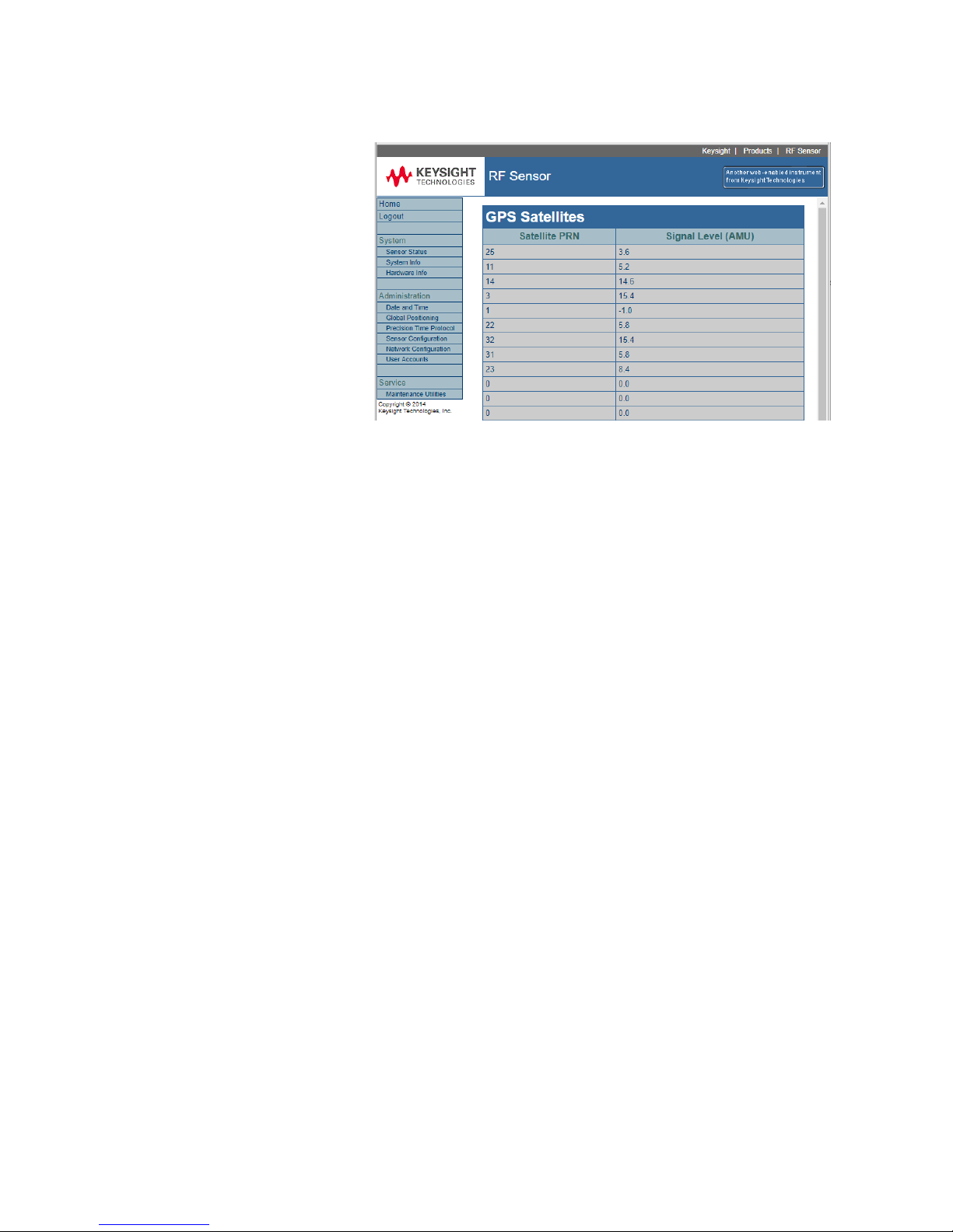
45 RF Sensor User Guide
GPS Satellites
Global Positioning ->GPS Satellites, shows the number of available satellites
and the relative signal strength from each.
Signal strength is shown in Amplitude Measurement Units (AMU), should be in
the 0 to +30 range. A negative AMU reading typically indicates satellites that
are at the horizon or something is blocking the signal. Larger positive AMU
values indicate the satellites are directly overhead with nothing blocking the
signal.
To get reliable time synchronization and location information, there should be
8 to 10 satellites with good AMU values.
AMU is like Carrier-to-Noise Ratio and can be derived from the following
formula:
CNO = 20log10 (AMU) + 22.8
AMU is also like SNR (Signal-to-Noise) Ratio.
The difference between CNO and SNR is:
CNO is used for a Modulated signal
SNR is used for non-Modulated signals
Page 48

46 RF Sensor User Guide
Appendix A
Receiver
Status
The SMT GPS Configuration and Status display displays the status of the RF
receiver. On the right-hand side of the display are eight status displays. The
following table lists the displays and their possible values.
Status
Values
Operating Stat
(one of these)
TimeSync — Running
TimeSync — Suspended
Receiver Mode
(one of these)
Automatic
Single Satellite
Horizontal
Full Position
DGPR Reference
Clock Hold
Overdetermined Clock
Time Sync Alarms
(zero or more of these)
GPS Comm Down
GPS Time Questionable
GPS Position Questionable
FPGA Time Not Set
OS Time Not Set
Avg FPGA Time Error Unknown
Supp Time Pkt Late
Prim Timing Pkt Late
GPS Minor Alarms:
(zero or more of these)
Antenna Input Open
Antenna Input Shorted
No Usable Satellites
Self-Survey in Progress
No Accurate Stored Position
Leap Second Pending
Receiver in Test Mode
Position Questionable
Almanac Not Current or Incomplete
PPS Not Generated
Decoding Status:
(one of these)
Doing Fixes
No GPS Time
PDOP Too High
No Satellites
Two Satellites
Three Satellites
Chosen Satellite Unusable
Traim Rejected Fix
Timing Mode:
(one of these)
Static
Mobile
Page 49

47 RF Sensor User Guide
Appendix B Port
Requirements
The Port Requirements appendix lists the ports used by the RF Sensor
software. These ports must be kept open by the network administrator.
B.1 Sensor Ports
SSH is reserved for support purposes.
The Control port (TCP 8080) is the most useful for programmed access. The
other ports are network local ports used for peer-to-peer time synchronization
and for local installation configuration.
B.2 Application Workstation Ports
Name
Port
Description
Direction
Protocol
http-alt
8080
SMS comms, RF Sensor
comms
Out
TCP
http
80
World Wide Web HTTP
Out
TCP
SAL
11067
Sensor Access Library
connection request
Out
TCP
SAL
>1024
Sensor Access Library data
In
TCP or UDP
Name
Port
Description
Direction
Protocol
Notes
http-alt
8080
RF sensor comms
In
TCP
RF Sensor software
version 1.4.0 or later
Discovery
2241
Discovery query
In
UDP
Discovery
2242
Discovery response
Out
UDP
IEEE1588
319
IEEE-1588-time
sync query
In
UDP
IEEE1588
320
IEEE-1588-time
sync response
Out
UDP
http
80
World Wide Web
HTTP
In
TCP
Required for firmware
updates on sensors with
firmware version 1.1.3 or
earlier
http-alt
8080
HTTP
Alternate
Out
TCP
http
80
World Wide Web
HTTP
Out
TCP
Obsolete
RF Sensor firmware
version 1.1.3 or earlier
SAL
11067 Sensor Access
Library connection
request
In
TCP
SAL
>1024 Sensor Access
Library data
Out
TCP or
UDP
Page 50
48 RF Sensor User Guide
B.3 Server Ports
Name
Port
Description
Direction
Protocol
Notes
http-alt
8080
RF Sensor
comms
Out
TCP
RF Sensor firmware version
1.4.0 or later
Protocol set in config file
mss
7021,
7022,
…
Sweep
synchronization
In
TCP
Different port for each
N6820E, set in config file
e3238s
7011
Remote control
for third party
applications
In
TCP
Set in config file
e3238sGeo
7015
Geo service
In
TCP
Set in
%SYS32%\drivers\etc\service
s
SAL
11067
Sensor Access
Library
connection
request
Out
TCP
Obsolete
RF Sensor firmware versions
1.1.3 or earlier
SAL
>1024
Sensor Access
Library data
In
TCP or
UDP
Name
Port
Description
Direct
ion
Protocol
http-alt
8080, 8081,
8082, …
RF Sensor
comms
Out
TCP
http-alt
8080
SMS comms
In
TCP
Discovery
2241
Discovery query
Out
UDP
Discovery
2242
Discovery
response
In
UDP
http
80
World Wide
Web HTTP
Out
TCP
Page 51
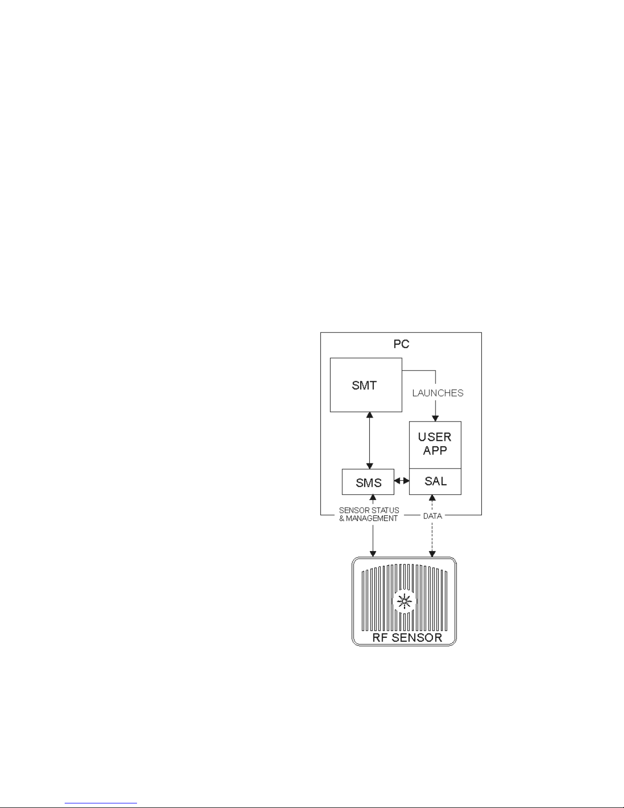
49 RF Sensor User Guide
Appendix C
Application
Programming
Overview
The RF Sensor and its associated software can be installed in many different
configurations. Five different examples of configurations are described in this
appendix. From these five examples, the full range of configurations can be
derived.
Example One
The first example of RF Sensor use is one RF Sensor and one PC. The PC runs
the Software Management System (SMS) as a service. The user starts the
Software Management Tool (SMT). Using SMT, the user identifies the
connected RF Sensor and takes control of it. SMT monitors the RF Sensor’s
status and controls its operation.
Using SMT, the user launches a user-written application. This user application
uses calls to the Software Application Layer (SAL) to control the RF Sensor
(using SMS) and to transfer Sensor data from the Sensor.
Page 52
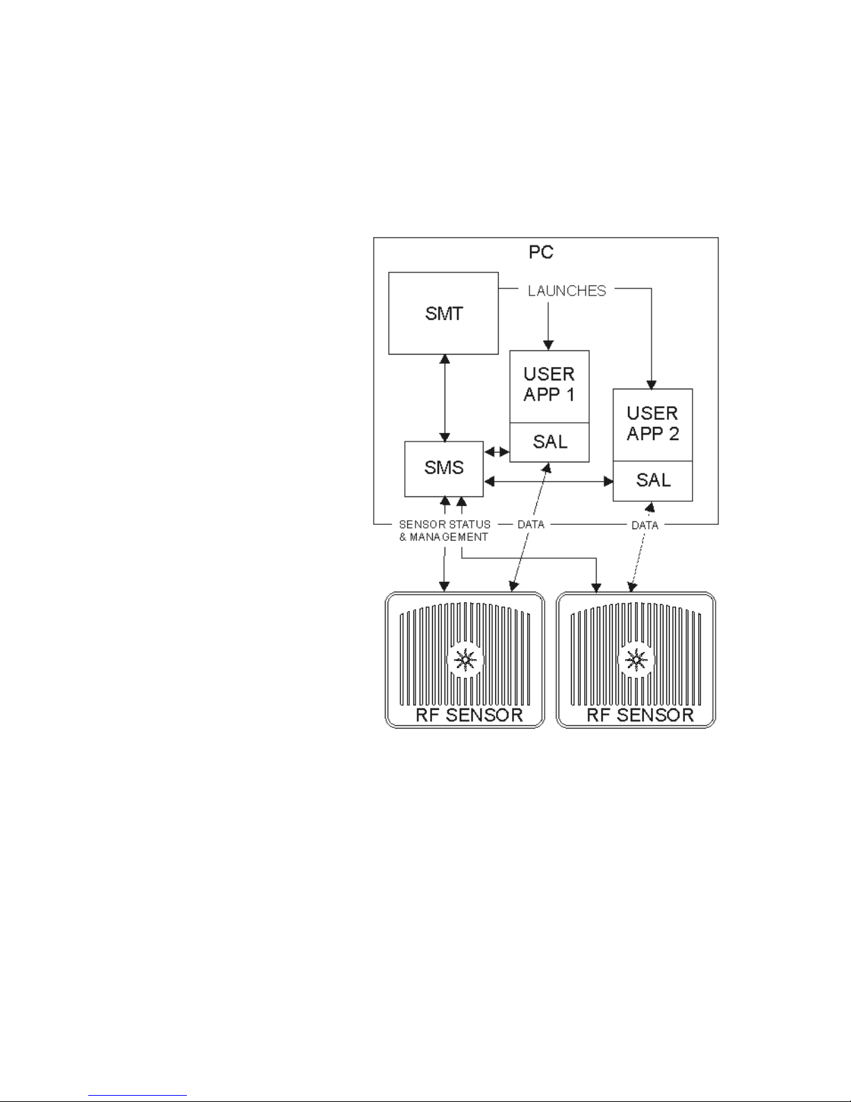
50 RF Sensor User Guide
Example Two
This second example of RF Sensor use is of one PC running multiple programs
and controlling multiple RF Sensors. The SMS manages the sensor and reports
the status to the SMT. The SMT launches user applications. The user
applications use SAL calls to communicate with the sensors. Multiple
instances of the same application can be run if the application is written to be
“thread safe.”
Page 53
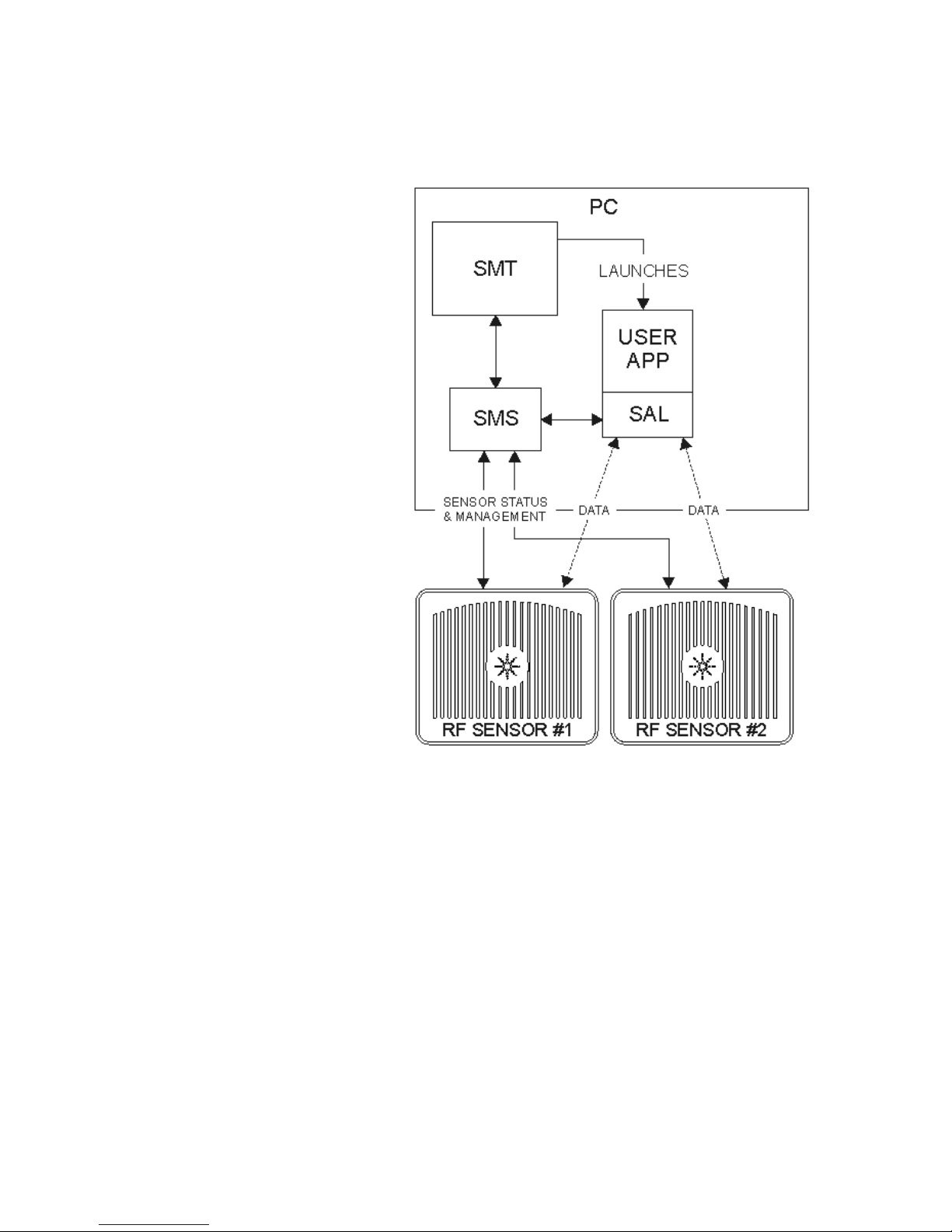
51 RF Sensor User Guide
Example Three
User applications can control multiple sensors. In the following diagram, a
user application is controlling and receiving data from two sensors. This
configuration can be used for applications using geolocation.
Page 54
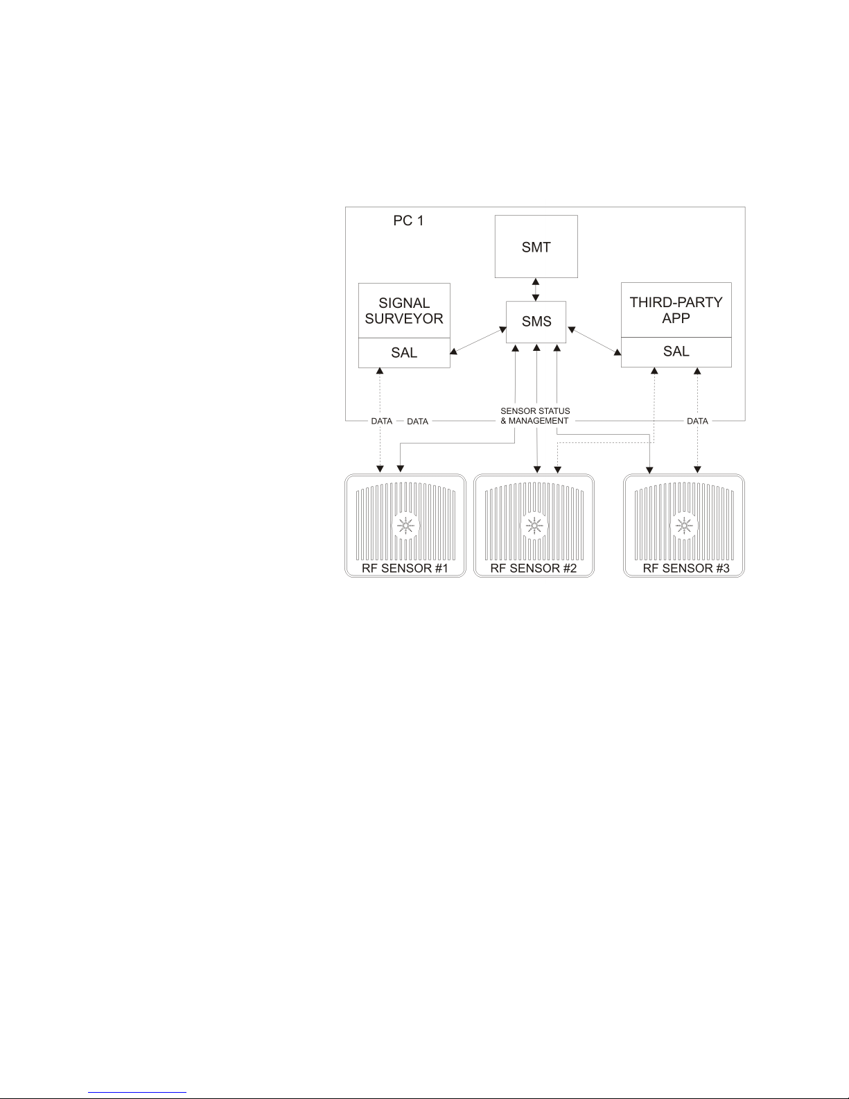
52 RF Sensor User Guide
Example Four
In the following diagram, two applications are running on a PC. This first
application is Signal Surveyor, which is receiving data from sensor #1. The
second application is a third-party application, communicating with sensors #2
and #3.
Page 55
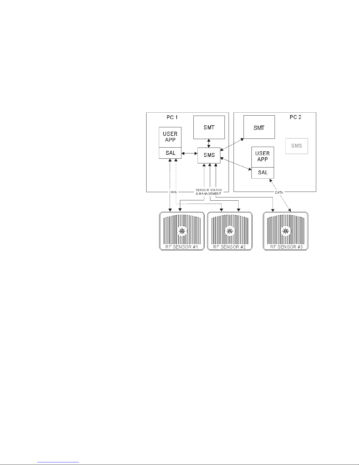
53 RF Sensor User Guide
Example Five
The SMS and SMT are also useful when applications execute on multiple
computers. In the following illustration, instances of SMT are running on two
different PCs. Each PC has an instance of SMS running as a service. User
applications on both PCs are controlling and receiving data from RF Sensors.
However, note that the instance of SMT on PC2 is controlling and monitoring
RF Sensor #3 through the SMS service running on PC1.
In this configuration, the single instance of SMS monitors all three sensors,
avoiding resource conflicts between the users of PC1 and PC2. All three
sensors are visible to, and available to both PCs.
Page 56
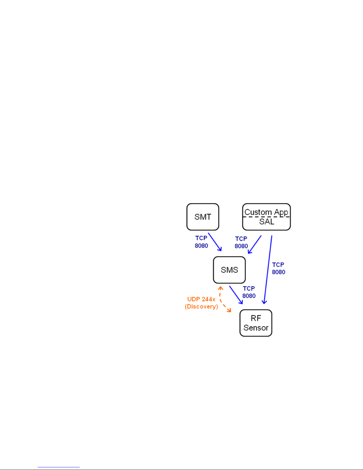
54 RF Sensor User Guide
Appendix D
Deploying RF
Sensor Networks
Deploying an RF Sensor network requires some basic knowledge of computer
networking. This guide describes different networking topologies for the RF
Sensor Software version 1.4.0 or later.
System Overview
An RF Sensor Network consists of RF sensors and a Sensor Management
Server (SMS). There can also be one or more Sensor Management Tool (SMT)
clients, or one or more applications such as the E3238S/N6820E Signal Survey
System or custom applications using the Sensor Access Library (SAL)
interface.
In an RF Sensor Network, TCP port 8080 is used for all operational
communications unless otherwise specified. UDP ports 2241 (SMS query) and
2242 (sensor response) are used for discovery of sensors in the same
broadcast domain (typically subnet) as the SMS. If the network uses IEEE1588 Precision Time Protocol (PTP), the RF sensors use UDP ports 319 (query
in) and 320 (response out) to communicate with the PTP-compatible network
components such as switches and routers.
Page 57
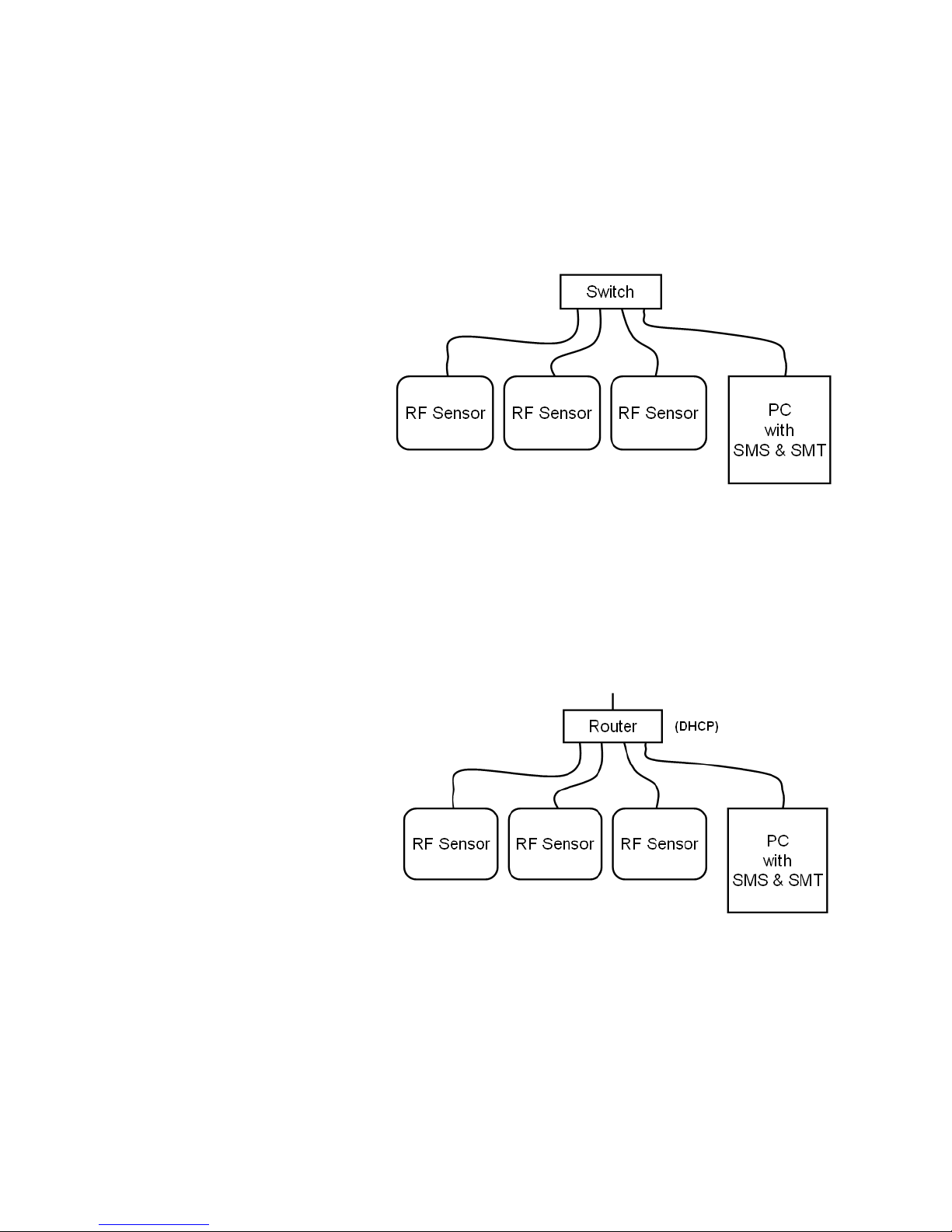
55 RF Sensor User Guide
Private Network
Using a switch and static IP addresses
Perhaps the simplest “table-top” network architecture is an Ethernet switch,
sensors, and a PC with the SMS and a client application such as SMT. This
architecture works well, but requires manually configuring static IP addresses
on each sensor and the PC. The easiest way is to use the SMT connected to
the SMS on the same machine (localhost) to discover sensors. Then modify
each sensor’s network parameters to be addressable by the PC.
Using a router and DHCP (recommended)
A more convenient architecture uses a router with the sensors and the PC
connected on the same side. The sensors and PC can be configured for
Dynamic Host Configuration Protocol (DHCP) and will receive their IP
addresses from the DHCP server in the router. With this architecture there is
no need to configure IP addresses and subnet masks. This architecture is
much like a typical home network where the other side of the router is usually
connected to the public internet.
Corporate Network
A sensor network on a corporate network is even easier to configure. Just
configure the sensors (and PC) for DHCP and the corporate network takes care
of the rest, including routing if using sensors on different subnets. Be aware
that the SMS discovery will only discover sensors on the same subnet, so any
sensors on different subnets will have to be added to the SMS explicitly. It is
possible to add a sensor by its hostname and the corporate network Domain
Name System (DNS) server will resolve this to its IP address This is analogous
to looking up someone’s phone number in a phone book.
Page 58
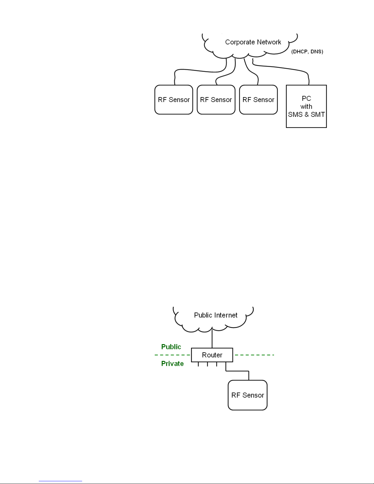
56 RF Sensor User Guide
Internal firewall
Some corporate networks have internally secure domains that are protected
from the rest of the corporate network by a firewall. For example, it is possible
to have sensors in a secure area and yet need to operate the sensor network
from a local office which is on the other side of the firewall. In order to allow
this, a TCP port 8080 needs to be opened on the firewall that isolates the
networks.
Public Access (not recommended)
Sometimes it may be desirable to configure a sensor network which uses the
public internet. This will require connection through a router to an Internet
Service Provider (ISP). The router will connect to the public internet and use
DHCP to assign private, unrouteable IP addresses (e.g. 192.168.x.x) to devices
on the private local area network (LAN). The router performs Network Address
Translation (NAT) between the private and public IP address provided by the
ISP. Typically, the router firewall settings will allow traffic initiated on the
private side, but block traffic initiated on the public side.
Page 59
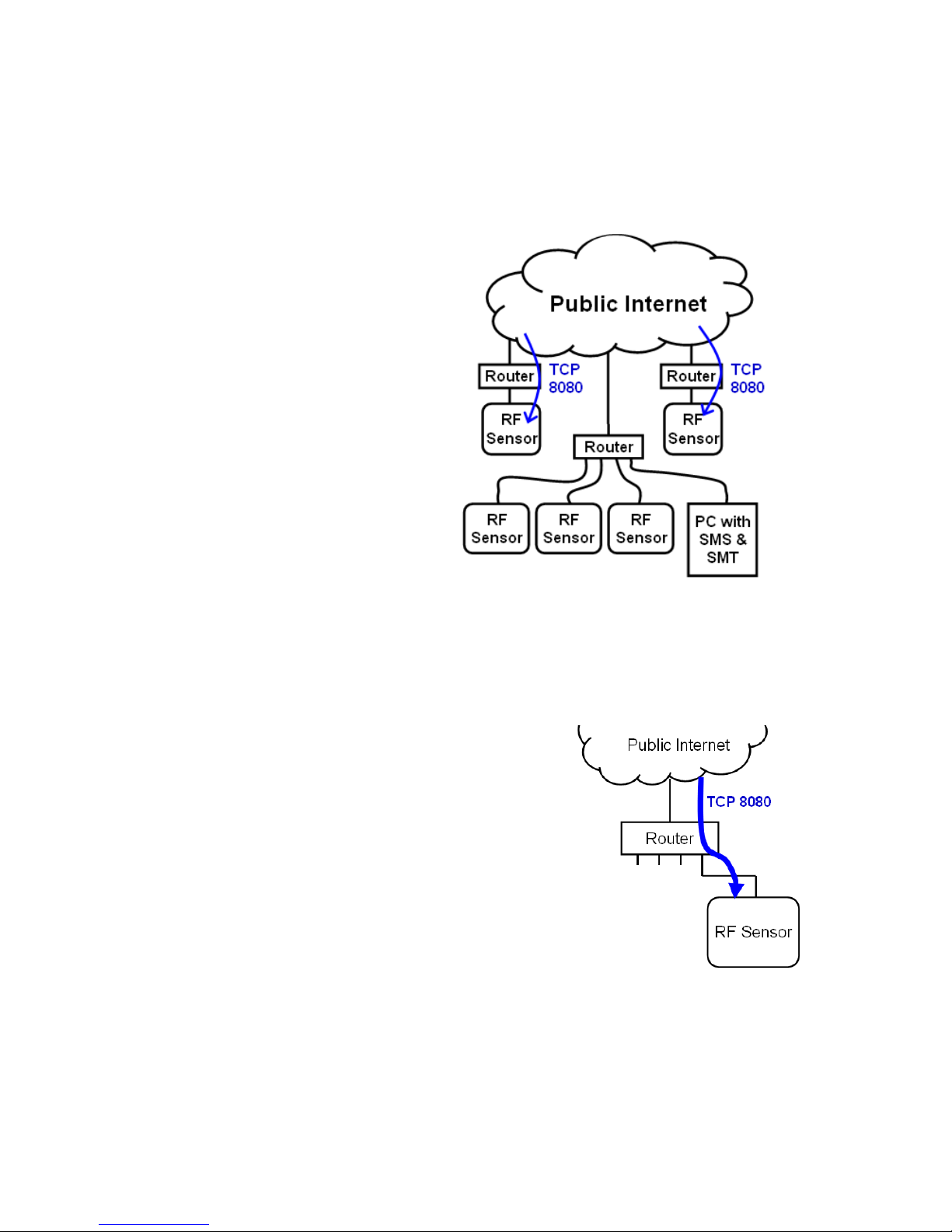
57 RF Sensor User Guide
Public remote sensors
To make an RF Sensor publicly accessible from the internet, set the router to
forward incoming TCP traffic on port 8080 to the sensor’s private IP address.
This is done under the “Port Forwarding” configuration section for the router.
Note that a port can be forwarded to only one private IP address. To have
more than one remotely-accessible sensor, assign each sensor a different port
number (8080, 8081, 8082, etc) when it is added it to the SMS. Each port can
then be forwarded to port 8080 on a different sensor.
Page 60
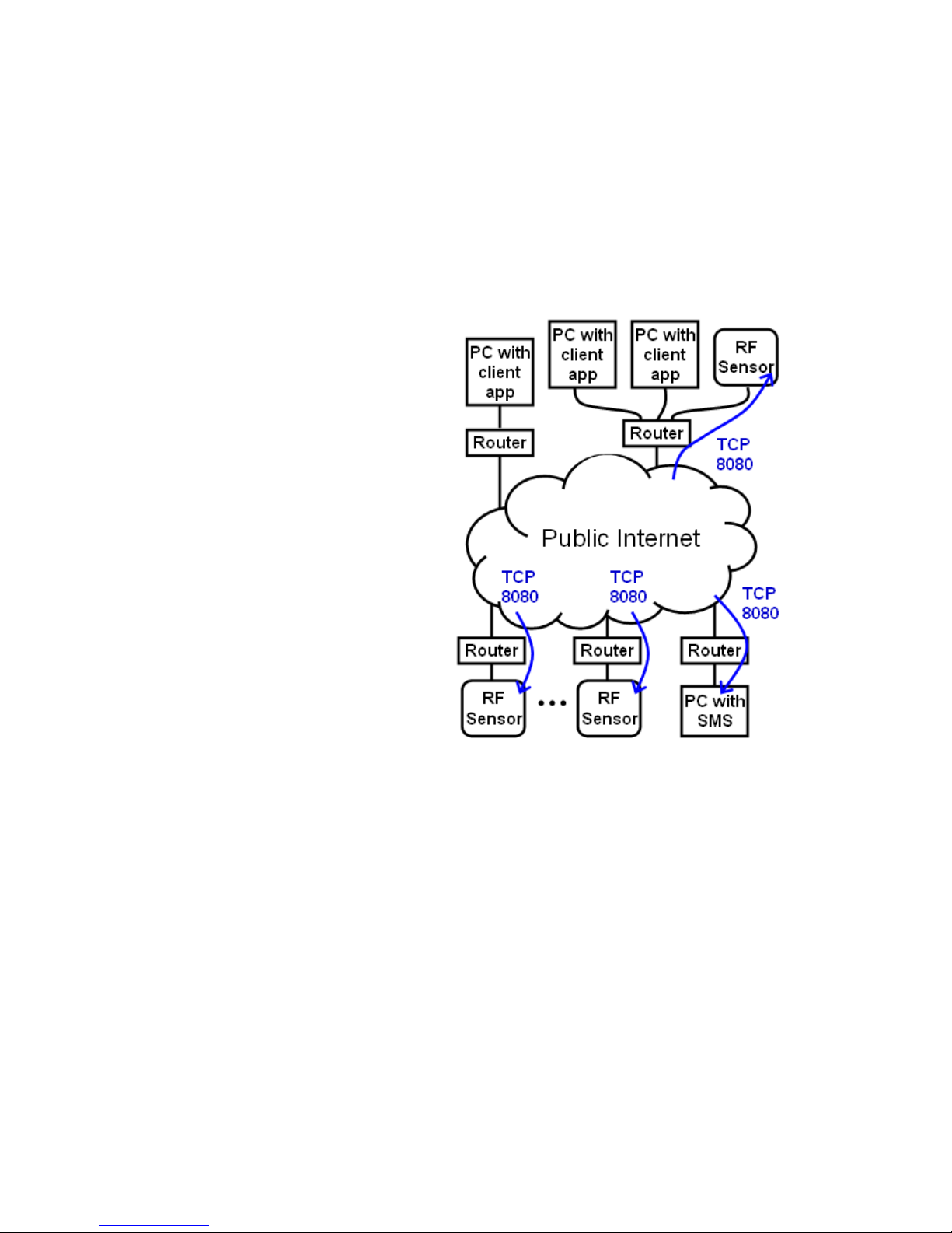
58 RF Sensor User Guide
Public remote SMS
To be able to access the SMS from a client application such as the SMT, the
N6820E Signal Survey System, or a custom application using SAL, the SMS
must be accessible from the internet. To do this, connect the PC running SMS
through a router to an ISP, and forward the incoming TCP port 8080 to the PC.
Enable incoming TCP 8080 on the Windows firewall may also be required.
Note that client applications will use the outgoing TCP port 8080 which is
enabled by default on most routers. The outgoing port is not shown in the
following figure.
Note: This configuration these sensors are remotely accessible to anyone on
the public internet. They can access the sensor’s web page and attempt to log
in. If they have an SMS they can take the sensor and add it to their SMS
sensor list. If the SMS is publicly accessible, it could be the target of an
attack.
Page 61
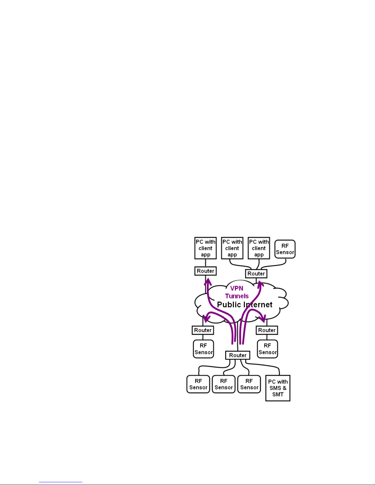
59 RF Sensor User Guide
Adding remote sensors to the SMS
To add the remote RF sensors to the SMS, the IP address or a hostname for
the sensor must be known. The ISP will usually not assign a static IP address,
but rather use DHCP to assign the IP address dynamically. Use a Dynamic
DNS (DDNS) service to resolve the sensor’s hostname into its dynamic IP
address. A DDNS service is used to create a hostname with one of their
domain names like “dyndns.org” or “homeip.net”. For example, a sensor could
be named “sensor7-example.dyndns.org” and the SMS “smsexample.dyndns.org”. There are several free DDNS services available, such as
www.no-ip.com or www.dynDNS.org. Create an account and a hostname,
then configure the router to update the DDNS server whenever its IP address
changes. If the router does not support DDNS, download software from the
DDNS provider that will run on the PC and update the DDNS server whenever
the router’s IP address changes.
Connecting a client to a remote SMS
To connect to the SMS from a remote client application such as the SMT the
IP address or a hostname for the PC running the SMS must be known. Again,
a DDNS service (or a static IP address) is needed.
Private Access Using a VPN
Secure Virtual Private Networks (VPNs) use cryptographic tunnelling protocols
and allow sender authentication. Once a VPN is established all the devices act
as though they are on a private network. Each sensor is directly accessible
through the VPN without port-forwarding, this enables multiple RF Sensors
and an SMS, all using TCP port 8080 behind a single router. The enhanced
security makes this the recommended architecture for a longer-term
deployment of a sensor network on the public internet. This will require
routers with VPN capability built-in.
Page 62

60 RF Sensor User Guide
Configuring the VPN routers
It is necessary to have DDNS (or a static IP address) to access the VPN routers
for remote configuration of the route tables and the VPN, and to establish the
VPN tunnels. The VPN tunnels can be established from either end, but a
convenient architecture is to establish the tunnels from the router with the
SMS to each of the other routers. The router with the SMS could be called the
“VPN initiator”.
Automatic VPN connection
Most often, to create a VPN tunnel to a remote location the user will enter the
name (or static IP) of the remote VPN router and it will present a login (name
and password) for authentication. However, an established VPN connection
can be lost due to power outages, an IP address re-assignment from the ISP,
or other network problems. For a robust and reliable sensor network, it is best
to automate the VPN re-connection process so it does not require manual
intervention. VPN routers can be programmed to remember the login
credentials (usually a private encryption key) and be able to automatically reestablish connections. Specifically, the VPN initiator router should be
configured to re-establish the VPN tunnels based on traffic.
The SMS heartbeat
The SMS maintains a steady heartbeat of short messages to the sensors on
TCP port 8080 (see figure 1) to request status information. This heartbeat
continues as long as 1) the sensor is being managed by the SMS, and 2) the
SMS is running. The heartbeat continues regardless of what client
applications are being used. The heartbeat continues even if a VPN
connection is lost, but without the VPN the heartbeat will not reach the sensor
and no status messages will be returned from the sensor. In the SMT, the
sensor status will show as “no check-ins” and the icon will turn gray. Because
the VPN initiator router is configured to re-establish the VPN based on traffic,
it will attempt to re-establish the VPN on every heartbeat. This robust
architecture will automatically maximize the availability of the sensor network.
Virtual private network example
In this example, there is a home office network in the “example.com” domain.
This example network has a DHCP and DNS server, and uses IP addresses in
the 172.16.0.0 to 172.16.30.255 range. The goal is to install an RF Sensor
network that uses RF sensors connected to the home office network, but also
in two other regions to the west and to the east where there is not currently
internet access. Additionally, the system should be able to use client
applications like SMT, E3238S Signal Surveyor, or any other application based
on the RF Sensor’s SAL API from the home office network or any of the
regions. A decision is made to use the public internet and a VPN to extend the
example.com domain to all the regions.
First, contact a local ISP and order internet access for the two new locations.
For clarity, the IP addresses dynamically assigned by the ISP are not shown in
figure 10.
Page 63
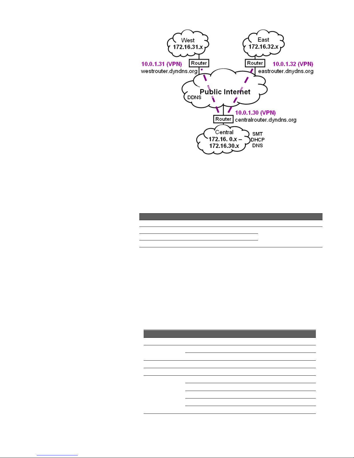
61 RF Sensor User Guide
Figure 10
The ISP-provided routers probably support DDNS but may not support VPN,
so we may need to buy routers that do.
Next, open three accounts with a DDNS provider for the hostnames “Centralrouter”, “West-router” and “East-router” and configure the routers for DDNS
so it is possible to configure and manage them by name from anywhere on the
internet.
DDNS Service Configuration
Router
Host Name
Authentication
Central
Central-router
User name / password
West
West-router
East
East-router
Configure the routers to create a VPN tunnel between the central and west
and central and east regions. The central router should automatically reestablish the VPN tunnels as needed from the SMS heartbeat.
Finally, configure the routing tables to extend the example.com domain to the
west and east regions across the VPN. The VPN will use the un-routable
10.x.x.x addresses “under the hood” but users will use hostname.example.com
(or 172.16.0.0 - 172.16.32.255 addresses) to access devices anywhere in the
west, central, or east regions.
VPN Configuration
Router
Settings
All
Private key = ***********
Reconnect on power up = on
West
Hostname = West-router
East
Hostname = East-router
Central
Hostname = Central-router
Host VPN address = 10.0.1.30
10.0.1.31 at westrouter.mydns.org
10.0.1.32 at eastrouter.mydns.org
Reconnect on traffic
Page 64

62 RF Sensor User Guide
Routing Tables
Router
Destination
Next hop
Central
172.16.31.x
10.0.1.31
172.16.32.x
10.0.1.32
West
172.16.x.x
10.0.1.30
East
172.16.x.x
10.0.1.30
Alternate topology for larger regional networks
This example has shown how to add remote sensors and yet keep them all in
the same domain so they act as though they are on a private network.
Consider an alternate topology with a domain for each region, like
west.example.com and east.example.com. This would require DNS and DHCP
servers in each region and would allow the regional network to operate
independently if the VPN is down for some reason. This topology may make
sense for larger regional networks which are used for more than just adding a
few sensors to the sensor network.
Time Synchronization
IEEE-1588 precision time protocol (PTP) can be used with the private networks
shown in figures 2 and 3 to ensure that all switches and routers are PTP
compliant. Corporate networks usually don’t support PTP well and the public
internet does not, so sensor networks like these will need to use GPS for time
synchronization. As mentioned earlier, the RF sensors will use UDP ports 319
(query in) and 320 (response out) to communicate with the PTP-compatible
network components such as switches and routers.
Page 65

\
This information is subject to change without notice.
@ Keysight Technologies 2014
Edition 1.2 April 2018
N6851-90001
www.keysight.com
 Loading...