

Page 1

Keysight N2902B Rack
Mount Kit for S-Series and
9000 Series Oscilloscopes
Installation
Guide
Page 2

Notices
CAUTION
WARNING
© Keysight Technologies, Inc. 2014
No part of this manual may be reproduced in
any form or by any means (including electronic storage and retrieval or translation into
a foreign language) without prior agreement
and written consent from Keysight Technologies, Inc. as governed by United States and
international copyright laws.
Manual Part Number
N2902-97002
Edition
Second edition, October 2014
Printed in Malaysia
Published by:
Keysight Technologies, Inc.
1900 Garden of the Gods Road
Colorado Springs, CO 80907 USA
Warranty
The material contained in this document is
provided “as is,” and is subject to being
changed, without notice, in future ed itions.
Further, to the maximum extent permitted
by applicable law, Keysight disclaims all
warranties, either express or implied, with
regard to this manual and any information
contained herein, incl uding but not l imited
to the implied warranties of merchantability
and fitness for a particular purpose. Keysight shall not be liable for errors or for incidental or consequential damages in
connection with the furnishing, use, or performance of this document or of any information contained herein. Should Keysight
and the user have a separate written agreement with warranty terms covering the
material in this document that conflict with
these terms, the warranty terms in the separate agreement shall control.
Technology Licenses
The hardware and/or software described in
this document are furnished under a license
and may be used or copied only in accordance with the terms of such license.
Restricted Rights Legend
If software is for use in the performance of a
U.S. Government prime contract or subcontract, Software is delivered and licensed as
“Commercial computer software” as defined
in DFAR 252.227-7014 (June 1995), or as a
“commercial item” as defined in FAR 2.101(a)
or as “Restricted computer software” as
defined in FAR 52.227-19 (June 1987) or any
equivalent agency regulation or contract
clause. Use, duplication or d isclosure of
Software is subject to Keysight Technologies’
standard commercial license terms, and
non-DOD Departments and Agencies of the
U.S. Government will receive no greater than
Restricted Rights as defined in FAR
52.227-19(c)(1-2) (June 1987). U.S. Government users will receive no greater than Limited Rights as defined in FAR 52.227-14
(June 1987) or DFAR 252.227-7015 (b)(2)
(November 1995), as applicable in any technical data.
Safety Notices
A CAUTION notice denotes a hazard.
It calls attention to an operating
procedure, practice, or the like that,
if not correctly performed or
adhered to, could result in damage
to the product or loss of important
data. Do not proceed beyond a
CAUTION notice until the indicated
conditions are fully understood and
met.
A WARNING notice denotes a hazard. It calls attention to an operating procedure, practice, or the like
that, if not correctly performed or
adhered to, could resul t in personal
injury or death. Do not proceed
beyond a WARNING notice until the
indicated conditions are fully
understood and met.
2 N2902B Rack Mount Kit
Page 3

In This Guide
This guide contains instructions for installing the Keysight N2902B Rack Mount
Kit. The rack mount kit provides a support shelf and hardware for mounting
Infiniium S-Series and 9000 Series oscilloscopes into Electronic Industries
Association (EIA) standard 19-inch (487-mm) rack cabinets.
Included Parts
The rack mount kit includes the following parts:
• Support tray
• Trim plate (consists of a bottom piece, top piece, and two side pieces)
• BNC connectors to be inserted into the bottom trim plate
• Black rubber stoppers to plug holes in bottom trim plate if the hole is not being
used for a BNC connection
•Two track rails
•Two feet brackets
• Sheet metal nuts
• Four sets of screws: cream-colored pan head screws for attaching the trim
plate pieces, metallic pan head screws for attaching the side rails to the rack,
metallic M4 screws for attaching the feet brackets to the support tray, and
another set of M4 screws for attaching the feet brackets to the oscilloscope.
N2902B Rack Mount Kit 3
Page 4
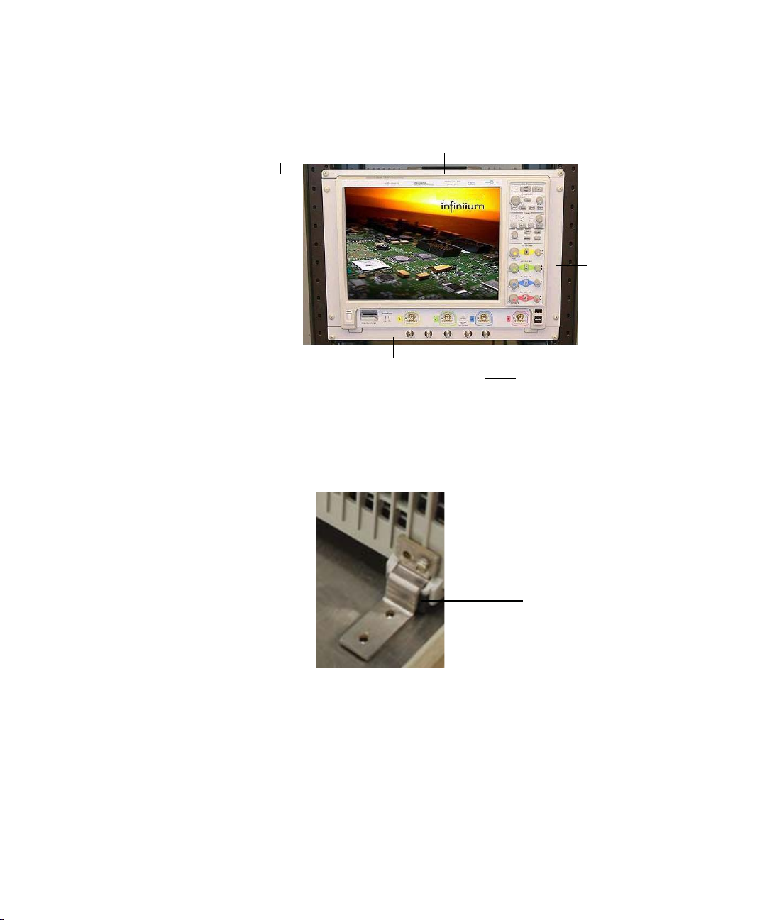
Top trim plate piece
Right
trim
plate
piece
Left
trim
plate
piece
Bottom trim plate piece
BNC connectors
Cream-colored screws
Feet bracket
4 N2902B Rack Mount Kit
Page 5
Installation
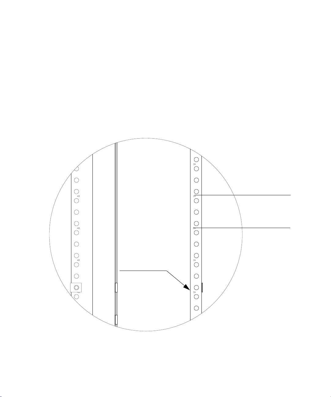
This distance is
equivalent to
1 rack unit
Rack front view
Rack side view
Rack units may be
designated by arrows.
If not, narrow hole spacing
indicates start/stop point
of rack unit.
The following tools are required for installing the rackmount kit:
• T20 Torx driver
• #2 Phillips screwdriver
Preparing the Rack
1 To prepare the rack for sheet metal nut installation, eight rack mount units
must be designated for use. The following diagram shows how to determine a
rack unit.
N2902B Rack Mount Kit 5
Page 6
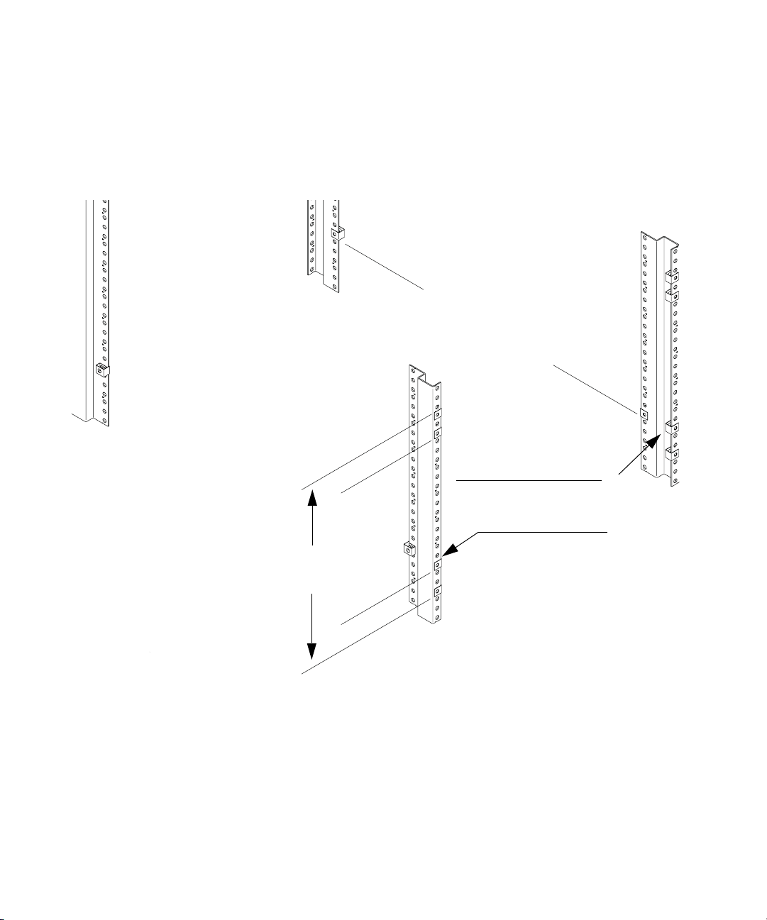
4 nuts installed for track
rail. Locations must align
Rear of Rack
Front of Rack
Distance from uppermost nut
to lowermost nut is equal
to 8 rack units (picture shows
To insure proper rail nut
installation, align with
this nut on front of rack.
front and rear.
only 7 rack units).
The following figure indicates proper locations for sheet metal nut locations. To
ensure a level installation, the same eight rack unit locations are used on each
vertical rack piece. NOTE: The picture shows only seven rack units.
6 N2902B Rack Mount Kit
Page 7
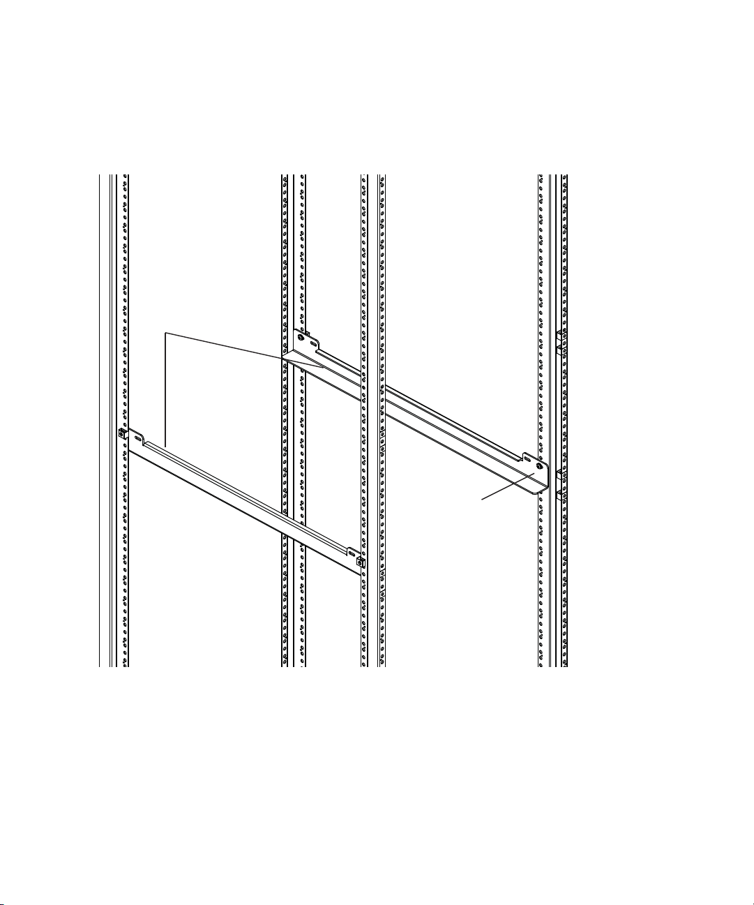
2 Attach the track rails to the rack using the four 10-32 pan head screws
Track rails
10-32 pan head
screws
provided and a #2 Phillips screwdriver.
N2902B Rack Mount Kit 7
Page 8
Installing the Oscilloscope into the Rack
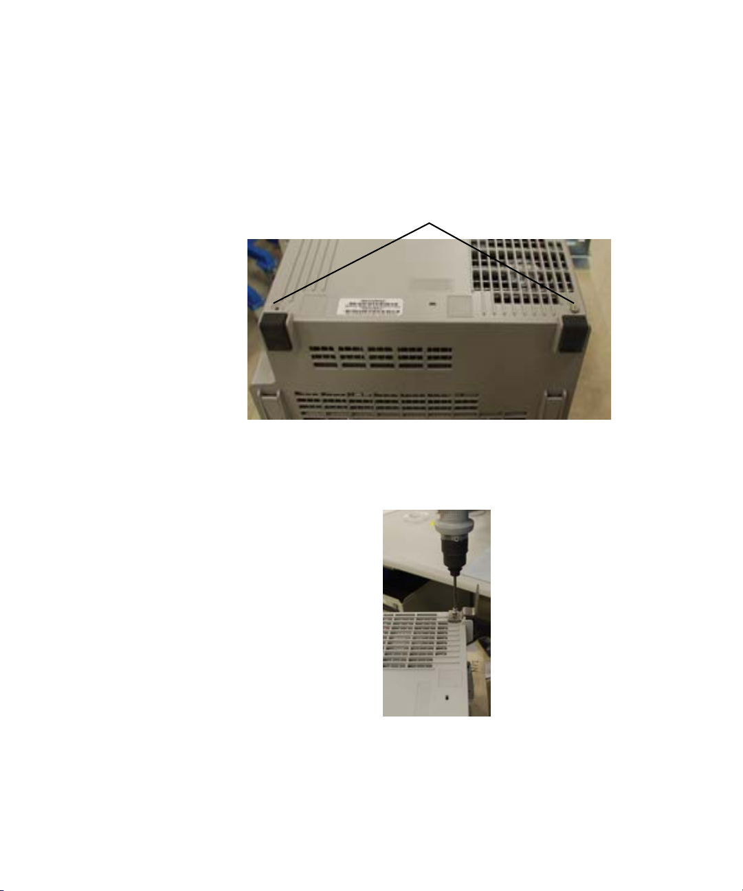
Remove screws
1 Remove the two M4 screws from the rear panel of the oscilloscope.
2 Attach the feet brackets to the oscilloscope using the two supplied M4 16mm
screws.
8 N2902B Rack Mount Kit
Page 9
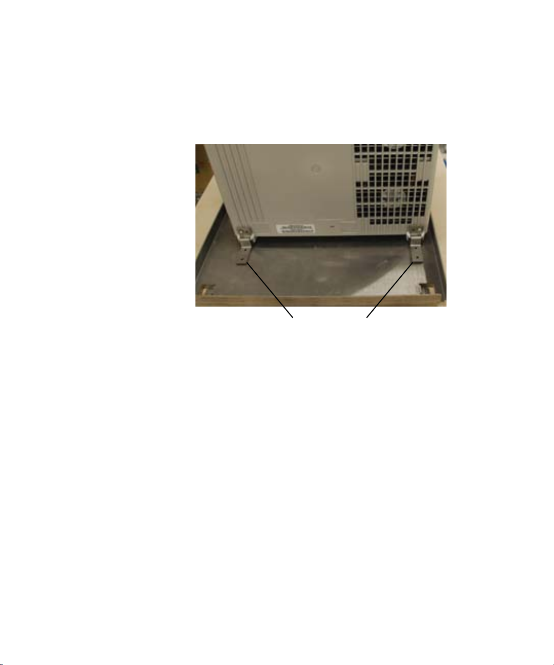
3 Place the support tray onto a table, then place the oscilloscope onto the
support tray. Line up the feet bracket screw holes with the holes in the support
tray.
Line up screw holes
4 Attach cables to the side panel BNC connectors on the oscilloscope and route
them under the oscilloscope through the indentation in the support tray. (Later,
these cables will be connected to the bottom trim plate BNC connectors so you
can have access to these BNCs once the oscilloscope is installed in the rack.)
Let the end of the cables that pass under the oscilloscope just dangle for now.
In a later step you will attach them to the bottom trim plate BNCs.
5 Plug the power cord into the oscilloscope and route it through the back so you
can plug it into a power outlet after installation.
N2902B Rack Mount Kit 9
Page 10
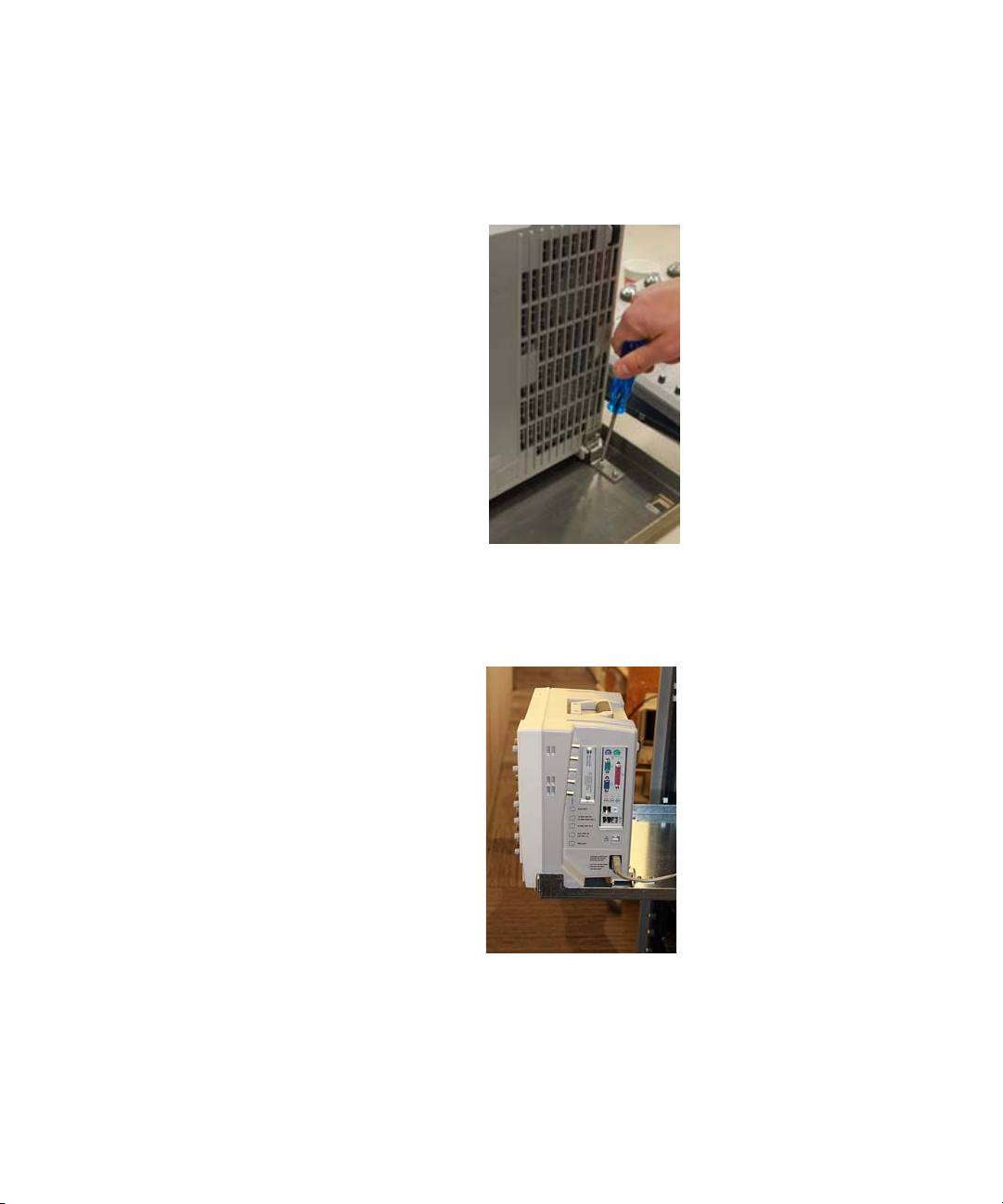
6 Use two M4 screws to secure each foot bracket to the support tray.
7 The oscilloscope and support tray should now look like the following picture
except you may have cables connected to the side panel BNCs if you chose to
attach them.
10 N2902B Rack Mount Kit
Page 11
8 Move the oscilloscope and support tray over to the rack. Using the rails, slide
the tray into the rack.
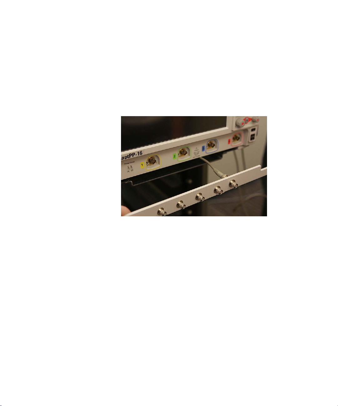
9 Connect the other end of each of the cables you routed under the oscilloscope
to one of the BNC connectors in the bottom trim plate piece as shown below. If
you do not want to install all five BNC connectors into the openings in the
bottom face plate, you can fill the holes with the supplied rubber stoppers.
.
10 Attach the bottom trim plate piece to the rack using two cream-colored pan
head screws. Then attach the side trim plate pieces using two cream-colored
pan head screws on each side. NOTE: When attaching the side face plate
pieces, be sure the screw holes are located toward the outside.
11 Attach the top trim plate piece to the rack with two cream-colored pan head
screws, being sure that it slides into the notch on the top of the oscilloscope.
N2902B Rack Mount Kit 11
Page 12
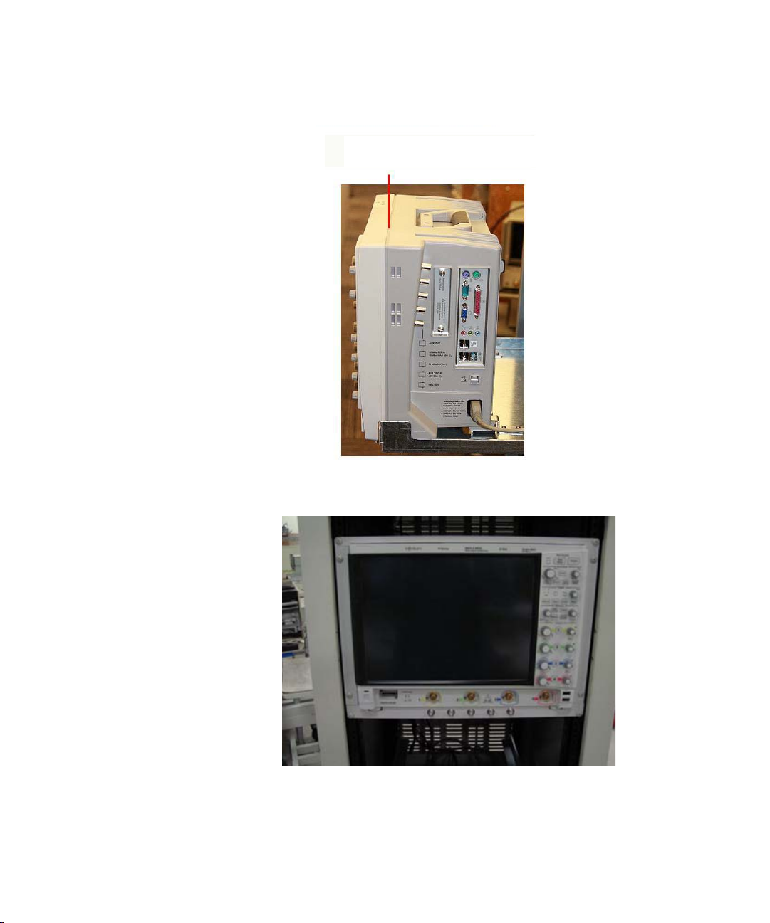
The top trim plate fits into this notch.
The oscilloscope is now fully installed and should look similar to the following
picture.
12 N2902B Rack Mount Kit
Page 13
Dimensions
32.5 cm
23.2 cm
32.8 cm
43.3 cm
48.3 cm
31.1 cm
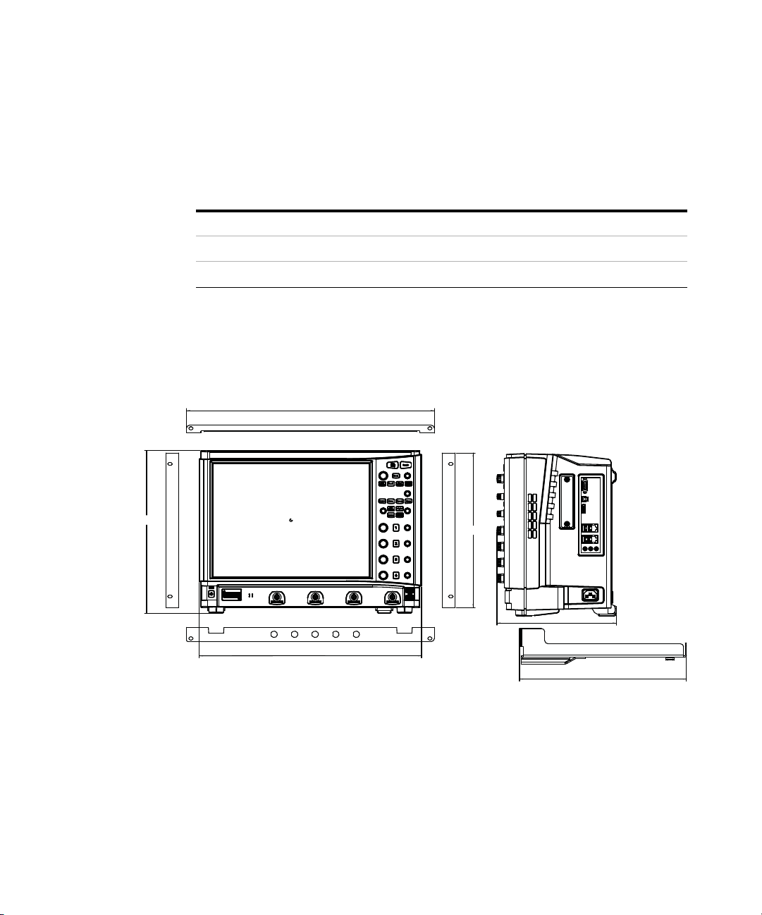
The following table shows the approximate dimensions for the rack mount trim
plate pieces.
Side trim plate pieces Bottom trim plate piece Top trim plate pieces
• Height: 31.1 cm (12.24 in) • Width: 48.3 cm (19 in) • Wid th: 48.3 cm (19 in)
• Wid th: 2.5 cm (0.985 in) • Height: 2.84 cm (1.12 in) • Height: 1.57 cm (0.62 in)
The following diagrams show the dimensions of an Infiniium S-Series oscilloscope
in an N2902B rack mount.
N2902B Rack Mount Kit 13
Page 14

This information is subject to change
without notice.
© Keysight Technologies, Inc. 2014
Printed in Malaysia
Second edition, October 2014
*N2902-97002*
N2902-97002
www.keysight.com
14 N2902B Rack Mount Kit
 Loading...