

Page 1
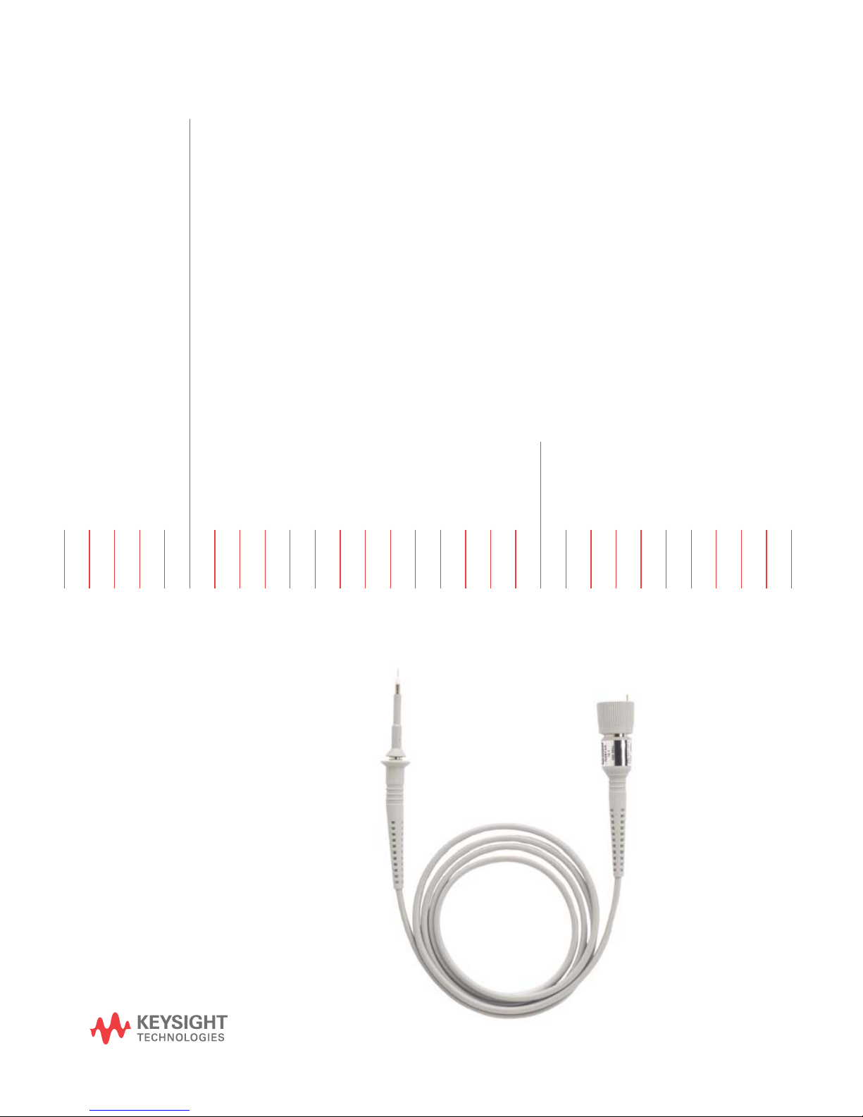
N2870A-Series and
N2894A Passive Probes
User’s
Guide
Page 2

Notices
CAUTION
WARNING
© Keysight Technologies, 2009
- 2014, 2016, 2018
This product complies
with the WEEE Directive
(2002/96/EC) marking
requirements. The
affixed label indicates
that you must not discard this electrical/electronic product in domestic
household waste. Product Category:
With reference to the equipment
types in the WEEE Directive Annex I,
this product is classed as a “Monitoring and Control instrumentation”
product. Do not dispose in domestic
household. To return unwanted products, contact your local Keysight
office, or refer to www.keysight.com
for more information.
This symbol indicates the
Environmental Protection
Use Period (EPUP) for the
product’s toxic substances for the
China RoHS requirements.
Recycle marking.
Manual Part Number
N2876-97002
Edition
October 2018
Printed in Germany
U.S. Government Rights
The Software is "commercial computer software," as defined by Federal
Acquisition Regulation ("FAR") 2.101.
Pursuant to FAR 12.212 and
27.405-3 and Department of Defense
FAR Supplement ("DFARS")
227.7202, the U.S. government
acquires commercial computer soft-
ware under the same terms by which
the software is customarily provided
to the public. Accordingly, Keysight
provides the Software to U.S. government customers under its standard
commercial license, which is embodied in its End User License Agreement
(EULA), a copy of which can be found
http://www.key-
at
sight.com/find/sweula
set forth in the EULA represents the
exclusive authority by which the U.S.
government may use, modify, distribute, or disclose the Software. The
EULA and the license set forth
therein, does not require or permit,
among other things, that Keysight: (1)
Furnish technical information related
to commercial computer software or
commercial computer software documentation that is not customarily
provided to the public; or (2) Relinquish to, or otherwise provide, the
government rights in excess of these
rights customarily provided to the
public to use, modify, reproduce,
release, perform, display, or disclose
commercial computer software or
commercial computer software documentation. No additional government
requirements beyond those set forth
in the EULA shall apply, except to the
extent that those terms, rights, or
licenses are explicitly required from
all providers of commercial computer software pursuant to the FAR
and the DFARS and are set forth specifically in writing elsewhere in the
EULA. Keysight shall be under no
obligation to update, revise or otherwise modify the Software. With
respect to any technical data as
defined by FAR 2.101, pursuant to
FAR 12.211 and 27.404.2 and DFARS
227.7102, the U.S. government
acquires no greater than Limited
Rights as defined in FAR 27.401 or
. The license
DFAR 227.7103-5 (c), as applicable
in any technical data. 52.227-14
(June 1987) or DFAR 252.227-7015
(b)(2) (November 1995), as applicable in any technical data.
Safety Notices
A CAUTION notice denotes a hazard. It calls attention to an operating procedure, practice, or the
like that, if not correctly performed or adhered to, could
result in damage to the product
or loss of important data. Do not
proceed beyond a CAUTION
notice until the indicated conditions are fully understood and
met.
A WARNING notice denotes a
hazard. It calls attention to an
operating procedure, practice, or
the like that, if not correctly performed or adhered to, could
result in personal injury or death.
Do not proceed beyond a WARNING notice until the indicated
conditions are fully understood
and met.
2
Keysight N2870A-Series and N2894A Passive Probes User’s Guide
Page 3

Contents
Introduction 4
Safety Information 7
Low-Frequency Compensation 9
Accessories 10
Available Accessories 17
Replacing Rigid, Solid Probe Tip, and Spring-Loaded Probe Tips 11
Short Ground Blade and Ground Spring 12
Sprung Hooks 13
15 cm Ground Lead 13
BNC Adapter 13
Copper Pads 14
Insulator Cap 14
Channel Identification Rings 14
IC Caps 15
PCB Adapter Kit 16
Accessories in Kits 17
Other Individually Orderable Accessories 21
Characteristics and Specifications 24
Performance Verification Procedures 29
Performance Verification Test Record 32
IEC Measurement Category Definitions 33
IEC Pollution Degrees Definitions 34
Keysight N2870A-Series and N2894A Passive Probes User’s Guide
3
Page 4

Introduction
Introduction
When used with a Keysight oscilloscope, the N2870A-Series and N2894A passive
probes set a new standard for “high performance” probing of up to 1.5 GHz. These
general purpose probes and accessories are a great choice if you are looking for
high quality at a very reasonable price.
Table 1 Probe Models
Model Band width
(-3 dB)
N2870A 35 MHz 1:1 39 pF
Attenuation
Ratio
Input C Input R
(scope +
probe)
1 MΩ 55 V CAT II 1 MΩ —
Max Input
Vol tage
(AC RMS)
Scope Input
Coupling
(+scope)
N2871A 200 MHz 10:1 9.5 pF 10 MΩ 400 V CAT I
300 V CAT II
N2872A 350 MHz 10:1 9.5 pF 10 MΩ 400 V CAT Ia
300 V CAT II
N2873A 500 MHz 10:1 9.5 pF 10 MΩ 400 V CAT Ia
300 V CAT II
N2874A 1.5 GHz 10:1 1.8 pF 500 Ω 8.5 V CAT I
N2875A 500 MHz 20:1 5.6 pF 20 MΩ 400 V CAT I
a
1 MΩ 10 - 25 pF
b
1 MΩ 10 - 25 pF
b
1 MΩ 10 - 25 pF
b
c
50 Ω —
a
1 MΩ 7-20 pF
300 V CAT
b
II
N2876A 1.5 GHz 100:1 2.2 pF 5 kΩ 21 V CAT I
N2894A 700 MHz
d
10:1 9.5 pF 10 MΩ 400 V CAT I
300 V CAT II
c
50 Ω —
a
1 MΩ 10 - 25 pF
b
a Measurement Category I, 1250 V transient overvoltage
bMeasurement Category II
c Measurement Category I, 0 V transient overvoltage
d 700 MHz bandwidth available with InfiniiVision 4000X/6000X with 1 GHz or higher bandwidth models only
Scope
Comp
Range
4
Keysight N2870A-Series and N2894A Passive Probes User’s Guide
Page 5

Faithful Reproduction of Signals
These probes offer bandwidths of 35 MHz, 200 MHz, 350 MHz, 500 MHz, 700 MHz,
and 1.5 GHz along with various attenuation ratios to address a wide range of measurement needs. For general purpose probing, the N2873A’s superior 10 M
resistance, 9.5 pF of low input capacitance, and low inductance ground connection
keep probe loading low enough to achieve high signal integrity measurements. The
1.5 GHz passive probe offers an even lower input capacitance for measuring faster
edges more accurately, making it a good low-cost alternative to an active probe. All
of these probes are automatically recognized when connected to Keysight
InfiniiVision and Infiniium Series oscilloscopes.
Easy Access to Signals
The compact design along with a 2.5 mm probe tip diameter provide better visibility
of the circuit under test when compared to the conventional 5 mm or 3.5 mm
probes. This makes it easier to probe today’s fine pitched ICs and components. To
learn more about probe tips and accessories, refer to “Accessories" on page 10.
Introduction
Ω input
Inspecting the Probe
• Inspect the shipping container for damage.
Keep the damaged shipping container or cushioning material until the contents
of the shipment have been checked for completeness and the probe has been
checked mechanically and electrically.
• Check the accessories.
If the contents are incomplete or damaged, notify your Keysight Technologies
Sales Office.
• Inspect the instrument.
If there is mechanical damage or defect, or if the probe does not operate
properly or pass performance verification tests, notify your Keysight
Technologies Sales Office.
If the shipping container is damaged, or the cushioning materials show signs of
stress, notify the carrier as well as your Keysight Technologies Sales Office. Keep
the shipping materials for the carrier’s inspection. The Keysight Technologies office
will arrange for repair or replacement at Keysight Technologies’ option without
waiting for claim settlement.
Keysight N2870A-Series and N2894A Passive Probes User’s Guide
5
Page 6

Introduction
CAUTION
Cleaning the Probe
Handling the Probe
Disconnect the probe and clean it with a soft cloth dampened with a mild soap and
water solution. Make sure the probe is completely dry before reconnecting it to an
oscilloscope.
Handle the probe with care to avoid injury, especially when it is fitted with the extra
thin and sharp spring contact tip.
The probe cable is a sensitive part of the probe and, therefore, you
should be careful not to damage it through excessive bending or pulling.
You should also avoid any mechanical shocks to this product in order to
guarantee accurate performance and protection.
6
Keysight N2870A-Series and N2894A Passive Probes User’s Guide
Page 7

Safety Information
WARNING
WARNING
WARNING
WARNING
WARNING
WARNING
To avoid personal injury and to prevent fire or damage to this product or
products connected to it, review and comply with the following safety
precautions. Be aware that if you use this probe assembly in a manner
not specified, the protection this product provides may be impaired.
Handle Probe Tips / Accessories Carefully. Some of the probe tips /
accessories are very sharp (the spring tips and ground spring, for
example). You should handle these with care to avoid personal injury.
Safety Information
Use Only Grounded Instruments. Do not connect the probe’s ground lead
to a potential other than earth ground. Always make sure the probe and
the oscilloscope are grounded properly.
Connect and Disconnect Properly. Connect the probe to the oscilloscope
and connect the ground lead to earth ground before connecting the
probe to the circuit under test. Disconnect the probe input and the probe
ground lead from the circuit under test before disconnecting the probe
from the oscilloscope.
Observe Probe Ratings. Do not apply any electrical potential to the probe
input which exceeds the maximum rating of the probe. Make sure to
comply with the voltage versus frequency derating curve on page 9.
Keep Away From Live Circuits. Avoid open circuitry. Do not touch
connections or components when power is present.
Keysight N2870A-Series and N2894A Passive Probes User’s Guide
7
Page 8

Safety Information
WARNING
WARNING
WARNING
Indoor Use Only. Do not operate in wet/damp environments. Keep
product surfaces dry and clean.
Do Not Operate With Suspected Failures Refer to qualified service
personnel.
Do Not Operate in an Explosive Environment.
8
Keysight N2870A-Series and N2894A Passive Probes User’s Guide
Page 9
Low-Frequency Compensation
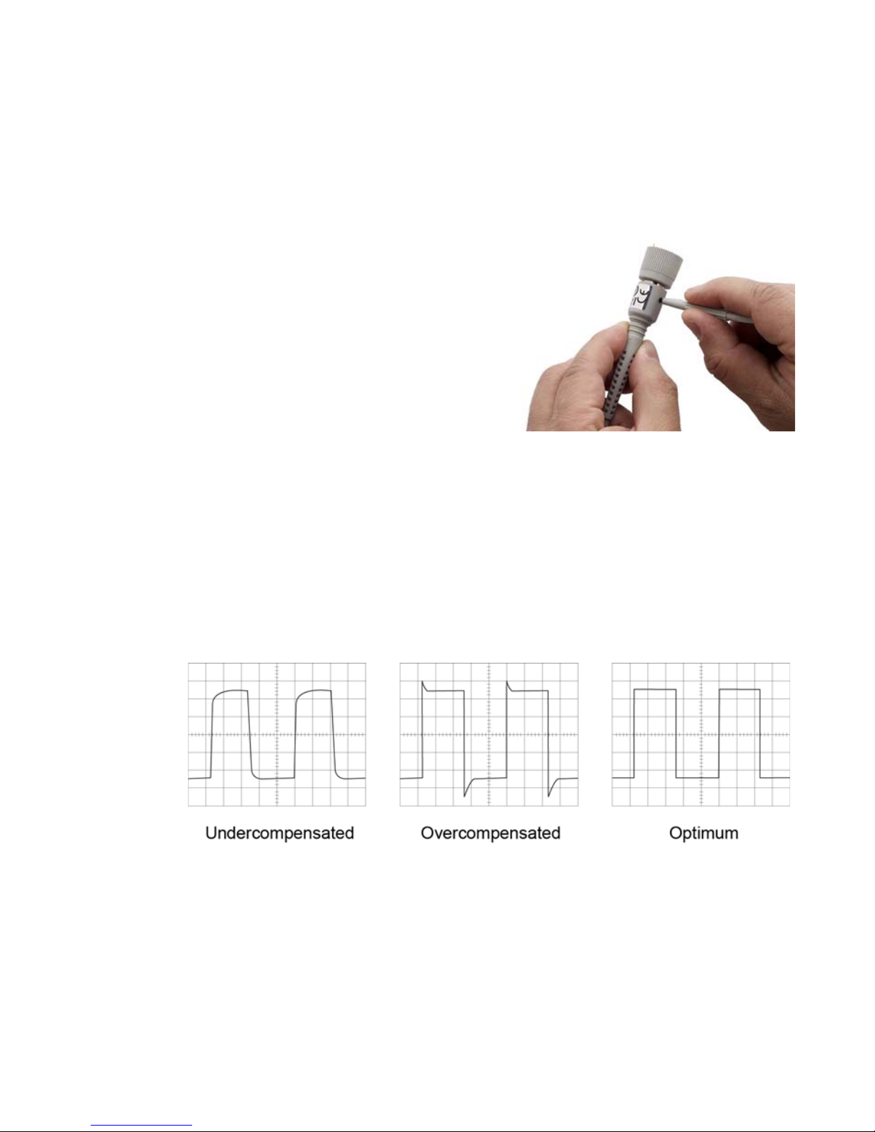
The N2871A, N2872A, N2873A, N2875A, and N2894A can be adjusted for low frequency (LF) compensation. The N2870A, N2874A, and N2876A cannot be adjusted.
The probe should be adjusted for LF compensation when it is connected to an oscilloscope input for the first time. LF
compensation matches the probe cable
capacitance to the oscilloscope input
capacitance. This matching assures good
amplitude accuracy from DC to the upper
bandwidth limit frequencies. A poorly compensated probe clearly influences the overall system performance (probe and
oscilloscope) and introduces measurement errors resulting in inaccurate readings
and distorted waveforms. To perform the LF compensation:
Low-Frequency Compensation
To perform the LF compensation:
1 Connect the probe to the oscilloscope’s front-panel calibration output (a square
wave label is usually seen near this output).
2 Use the supplied trimmer tool to adjust the LF compensation to an optimum
square wave response as shown in this picture.
Figure 1 LF Compensation
Keysight N2870A-Series and N2894A Passive Probes User’s Guide
9
Page 10

Accessories
Accessories
The probe comes with the accessories listed in Table 2. For a broader range of
available accessories, order the accessory kits described in “Available Accessories" on
page 17.
Table 2 Supplied Accessories
Accessory Quantity N2871A,
N2872A,
N2873A,
N2875A,
N2894A
Spring-loaded probe tips 2
Rigid probe tips 2
Ground blade 2.5 mm 1
Ground spring 2.5 mm 1
Sprung hook 2.5 mm 1
Short sprung hook 2.5 mm 1
Ground lead 15 cm 1
Copper pads 2
IC cap 2.5 - 0.5 mm green 1
N2870A N2874A,
N2876A
IC cap 2.5 - 0.65 mm blue 1
IC cap 2.5 - 0.8 mm gray 1
IC cap 2.5 - 1.0 mm brown 1
IC cap 2.5 - 1.27 mm black 1
BNC adapter 2.5 mm 1
Insulating cap 2.5 mm 1
Protection cap 2.5 mm 1
10
Keysight N2870A-Series and N2894A Passive Probes User’s Guide
Page 11
Accessories
Accessory Quantity N2871A,
N2872A,
N2873A,
N2875A,
N2894A
Trimmer tool 1
Color coding rings 3x4 colors
User’s Guide 1
N2870A N2874A,
Replacing Rigid, Solid Probe Tip, and Spring-Loaded Probe Tips
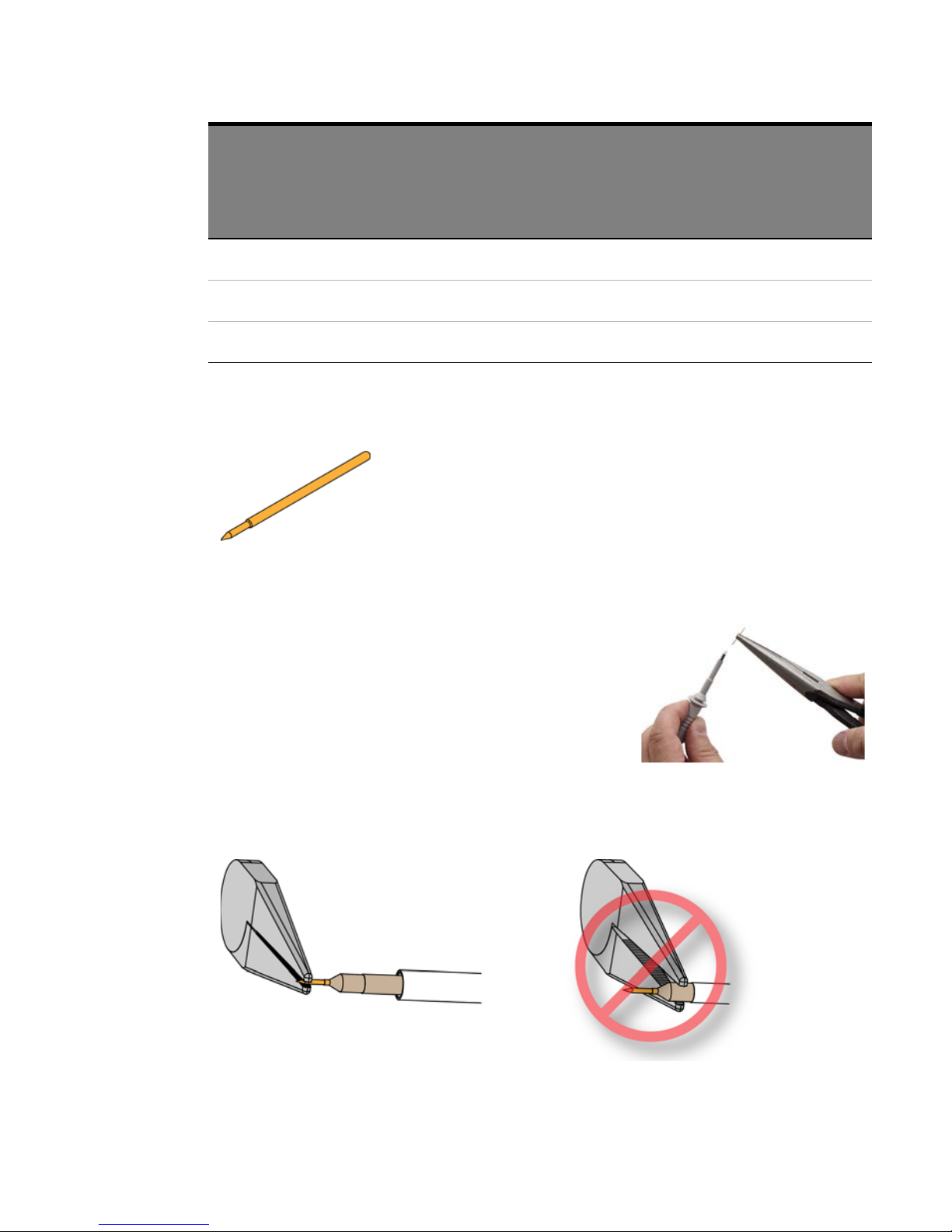
The solid tips and spring-loaded tips are replaceable. Spring
loaded probe tips offer a method of probing signals that is
less susceptible to vibration or movement than traditional
rigid tips. Many users find it easier to use this type of tip. The
spring loaded tips work when they are either partially or fully
compressed and are protected against over compression
damage.
N2876A
To change the probe tip, use pliers to grip the tip
and pull it straight out of its contact socket along
the axis of the probe. Do not grip the plastic insulator or the housing with the pliers because the tip
could be crushed (see Figure 2). This could result in
being unable to remove the tip and/or damaging
the probe. Once the probe tip is removed, the new
tip can be inserted with pliers into the contact socket along the axis of the probe. In
order to insert the probe tip completely into the housing, carefully press the probe
tip against a hard surface.
Keysight N2870A-Series and N2894A Passive Probes User’s Guide
11
Page 12
Accessories
WARNING
Short Ground Blade and Ground Spring
Figure 2 Proper Tip Removal Technique
You should exercise caution when using these sharp probe tips to avoid
personal injury.
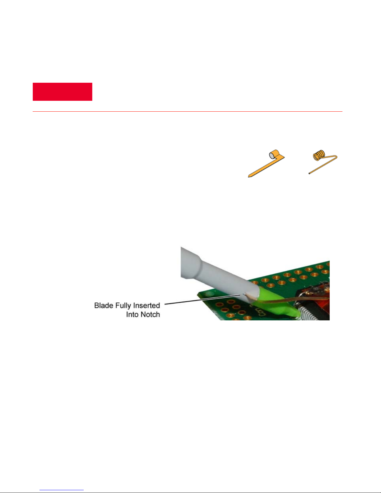
The short ground blade is the best performing
ground connection available due to its low inductance. To attach the ground blade, simply push it
over the probe tip and continue pushing until the
blade is inserted into the notch located on the probe
barrel, as shown in Figure 3. This will keep it from spinning around on the probe
while in use. You can also bend and form the blade to reach your grounding location. In the picture, you can see that the ground blade was placed over the tip and
then an IC cap accessory was placed over the tip.
Figure 3 Blade inserted into the Probe Notch
The ground spring offers similar performance as the ground blade and depending
on the probing situation, may offer greater flexibility when making a ground connection. The ground spring is also inserted over the probe tip in a similar manner. It
is mainly used for browsing as it is flexible and snaps back to original orientation
(unlike the ground blade that you can form) which allows you to connect it to your
grounding location and then move the probe tip around. It does have a slightly
larger inductance than the ground blade which may result in some decrease in performance depending on the application.
12
Keysight N2870A-Series and N2894A Passive Probes User’s Guide
Page 13
Sprung Hooks
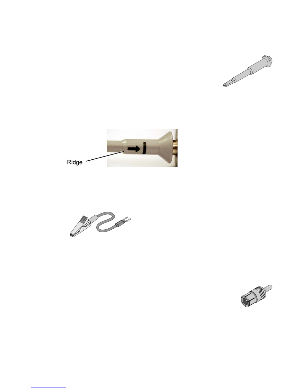
You will see a gray line (shown as black in the picture
below) with an arrow pointing towards it on the barrel of
your N287XA Series probe. This is used as a marker to tell
you when you have pushed the sprung hook completely
onto the probe. When inserting the sprung hook onto the
probe barrel, push until you feel it lock onto the ridge (see
Figure 4). If you do not push the sprung hook to this point so it can engage and
“lock on” to the probe, the accessory may fall off or suffer a decrease in performance. If the sprung hook is correctly attached then the gray marking line should
be covered when the hook is fully extended
Accessories
Figure 4 Ridge Location on Probe
15 cm Ground Lead
BNC Adapter
Both the rigid and spring-loaded probe tips are compatible with
this adapter.
This ground lead can be used to reach grounding locations that are farther away from the probing location
than can be reached by either the ground blade or
ground spring. However, the longer lead means it has
a larger inductance in the ground return path which
corresponds to a lower performance than these other
two grounding accessories.
Keysight N2870A-Series and N2894A Passive Probes User’s Guide
13
Page 14
Accessories
Copper Pads
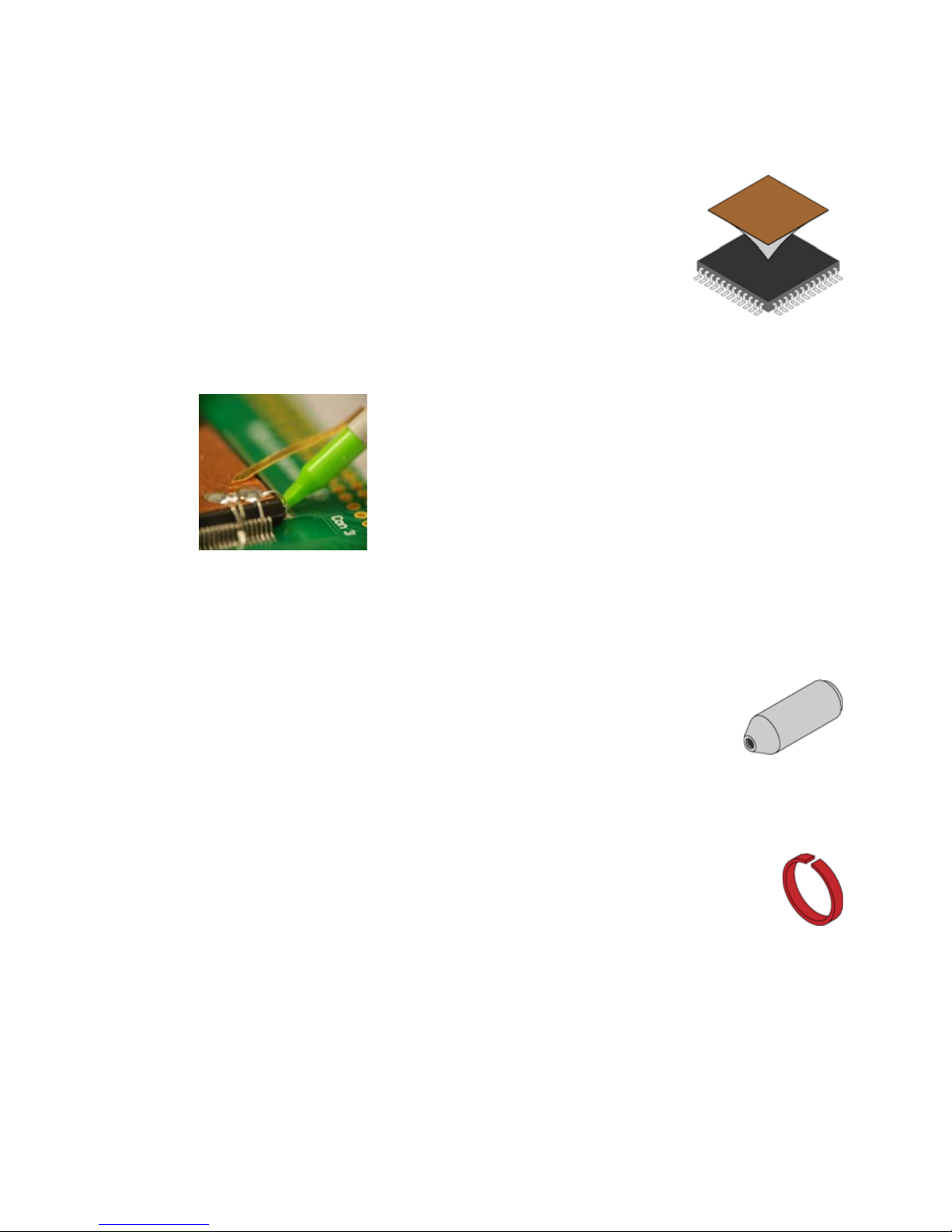
These self adhesive copper pads can be attached on top of
an IC and connected to its ground pins to create a convenient ground plane for the probe to connect to. When used
with the ground blade, this method provides an ideal
ground connection for probing signals with high frequency
content. However, to maximize the performance of this
setup, you need to connect the copper pad to as many
grounding locations as possible.
Figure 5 Copper Pad on IC
Insulator Cap
This cap fits over the probe tip and covers the ground barrel of the
probe, covering any potential shorting locations near the tip. This
enables you to probe in hot environments without having to worry
about shorts.
Channel Identification Rings
The channel identification rings can be used to keep track of which
probe is connected to which channel input on your oscilloscope. Place
one ring on the probe cable near the oscilloscope input and place
another ring of the same color near the probe head. This ensures that
you can pick up a probe and immediately know which channel it is connected to without having to track the cable back to the oscilloscope channel input.
14
Keysight N2870A-Series and N2894A Passive Probes User’s Guide
Page 15
IC Caps
Accessories
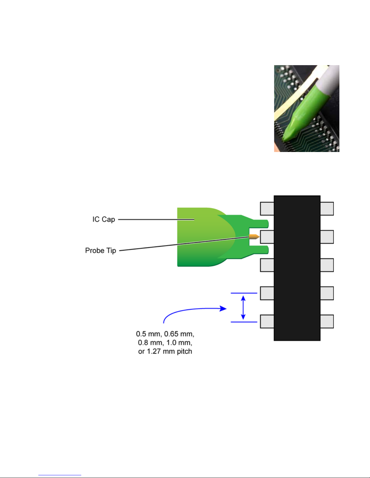
The IC caps fit over the probe tip and provide a convenient
self-aligning connection to an IC’s pins. This helps maintain contact on small fine pitch legs and prevents shorting
adjacent pins by preventing the probe tip from sliding
between the legs of the component.
The different colored IC caps correspond to different
pitches as listed in Table 2 on page 10.
Figure 6 shows how pitch is measured and how the caps
fit around the IC pins and where the probe tip comes
through the cap. IC caps are compatible with both the
rigid and spring loaded tips.
Figure 6 View of Top of IC with IC Cap Positioned Over IC Pin (not drawn to scale)
Keysight N2870A-Series and N2894A Passive Probes User’s Guide
15
Page 16
Accessories
PCB Adapter Kit
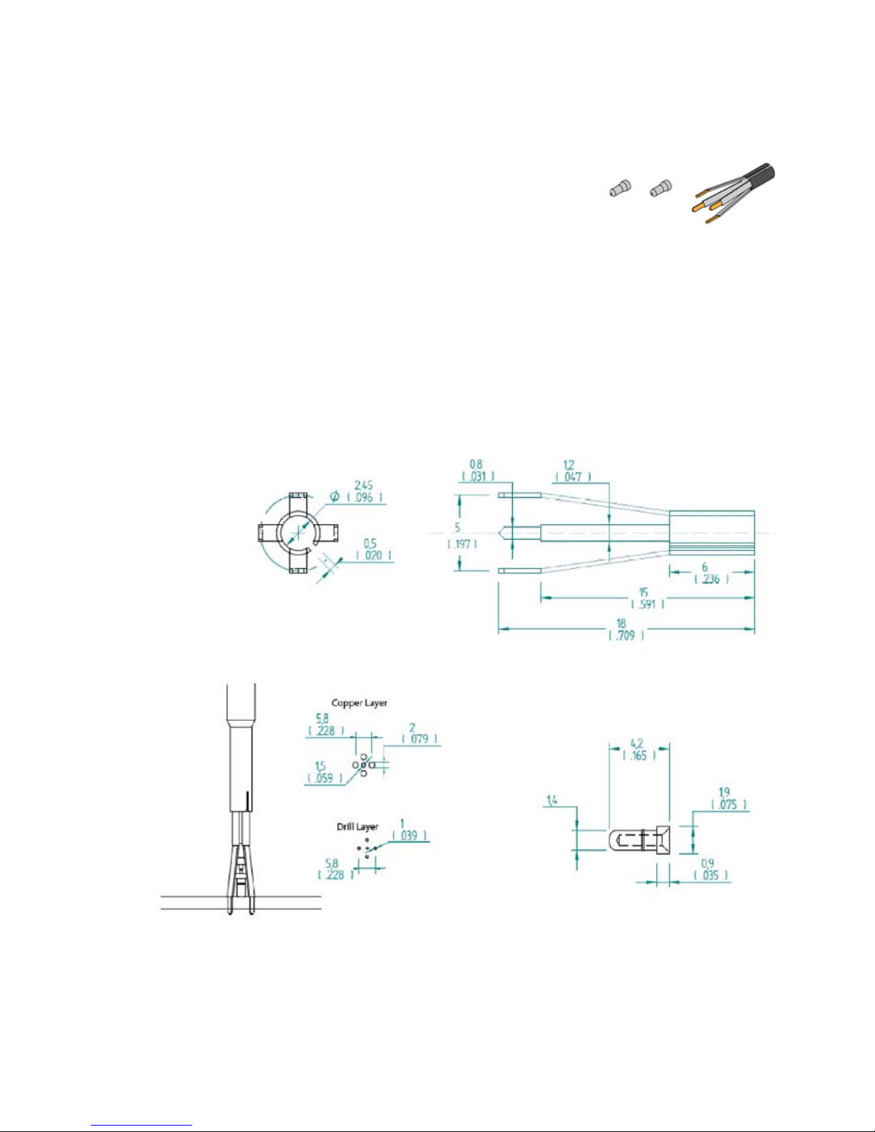
The PCB Adapter Kit is not included in the Standard
Accessories. However, the PCB Adapter Kit does not
include its own documentation so its features will be
documented in this User’s Guide. The PCB Adapter
sockets are designed to solder into a printed circuit
board (PCB) as test points to minimize ground inductance and maximize signal
fidelity.
The recommended PCB layout is shown in Figure 7. The PCB socket is compatible
with hand soldering and reflow processes. After soldering the socket - both the signal contact and ground contact - to the board, simply insert the probe. The PCB
adapter is compatible with either the rigid or spring-loaded probe tip.
Figure 7 Recommended PCB Layout
16
Keysight N2870A-Series and N2894A Passive Probes User’s Guide
Page 17
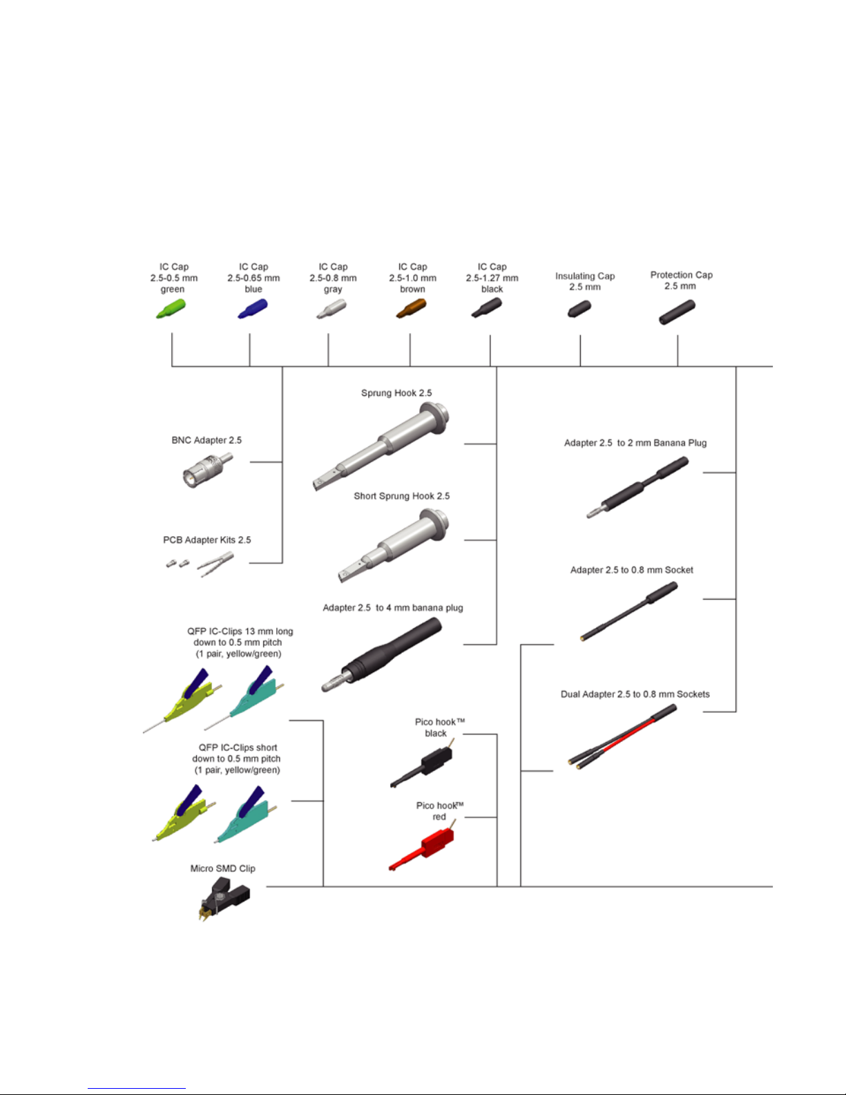
Available Accessories
Accessories in Kits
The available accessories shown in this picture are listed in Table 3 on page 19 with
their associated accessory kits.
Available Accessories
Keysight N2870A-Series and N2894A Passive Probes User’s Guide
17
Page 18
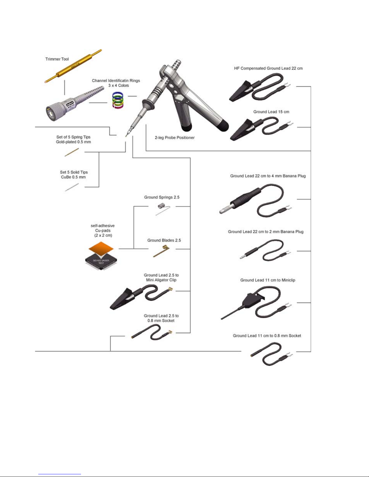
Available Accessories
18
Keysight N2870A-Series and N2894A Passive Probes User’s Guide
Page 19

Table 3 Accessory Quantity in Kits
Available Accessories
Optional Accessory N2877A
Deluxe
Kit
N2879A
Fine Pitch
Kit
N2878A
General
Purpose Kit
N2885A
PCB Socket
Adapter Kit
Accessory
P/N
IC Cap 2.5 - 0.5 mm green 3 3 1 — 0960-2983
IC Cap 2.5 - 0.65 mm blue 3 3 1 — 0960-2984
IC Cap 2.5 - 0.8 mm gray 3 3 1 — 0960-2988
IC Cap 2.5 - 1.0 mm brown 3 3 1 — 0960-2989
IC Cap 2.5 - 1.27 mm black 3 3 1 — 0960-2986
Insulating Cap 2.5 mm 1 1 1 — 0960-2985
Protection Cap 2.5 mm 1 1 1 — 0960-2996
LF Compensation Trimmer Tool 1 — — — —
HF Compensated Ground Lead 22 cm 1 — — — 0960-2993
Ground Lead 22 cm to 4 mm banana plug 1 — — — —
Ground Lead 22 cm to 2 mm banana plug 1 — — — —
Ground Lead 11 cm to miniclip 1 — — — 0960-2977
Ground Lead 11 cm to 0.8 mm socket 1 — — — 0960-2978
Ground Spring 2.5 mm 3 3 — — 0960-2980
Self-adhesive Cu-pads
10 10 10 — 0960-2908
(2 x 2 cm)
Ground Blade 2.5 mm 3 3 1 — 0960-2982
Ground Lead 2.5 to mini Alligator Clip 1 — — — 0960-2991
Ground Lead 2.5 to 0.8 mm socket 1 — — — 0960-2994
Set of 5 Spring Tips Gold-plated 0.5 mm 1 1 1 — 0960-2981
Set of 5 Solid Tips CuBe 0.5 mm 1 1 1 — 0960-2979
Adapter 2.5 to 2 mm banana plug 1 — — — —
Adapter 2.5 to 0.8 mm socket 2 — — — 0960-2990
Dual Adapter 2.5 to 0.8 mm sockets 2 2 — — 0960-2898
Keysight N2870A-Series and N2894A Passive Probes User’s Guide
19
Page 20

Available Accessories
Optional Accessory N2877A
Deluxe
Kit
N2879A
Fine Pitch
Kit
N2878A
General
Purpose Kit
N2885A
PCB Socket
Adapter Kit
Accessory
P/N
Sprung Hook 2.5 mm 1 — 1 — 0960-2905
Short Sprung Hook 2.5 mm 1 — — — 0960-2907
Adapter 2.5 to 4 mm banana plug 1 — — — —
Pico Hook black 2 2 — — —
Pico Hook red 2 2 — — —
BNC Adapter 2.5 mm 1 — — — 0960-2987
PCB Adapter Kit 2.5 mm 1 10 — 25 —
QFP IC-Clips 13 mm long down o 0.5 mm
22——0960-2992
pitch (1 pair yellow/green)
QFP IC-Clips short down to 0.5 mm pitch
22——0960-2995
(1 pair yellow/green)
Ground Lead 15 cm 1 — 1 — 0960-2906
Channel Identification Rings, 4 colors 3 — 3 — —
2-leg Probe Positioner 1 1 — — N2786-6000
1
Micro SMD Clip 12———
20
Keysight N2870A-Series and N2894A Passive Probes User’s Guide
Page 21

Other Individually Orderable Accessories
This section lists the accessories that are not included with the accessory kits mentioned in the previous section but can be ordered individually.
Table 4 Other Individually Orderable Accessories
Model Number Description For use with Qty per kit
Available Accessories
N4829A Probe tip kit (Rigid and
spring loaded)
N4831A Sprung hook tip N2870A-76A, N2894A
N4836A Dual lead adapter
2.5mm, 10cm
N4837A Ground lead, 15cm N2870A-76A, N2894A
N4838A Ground Spring, 2.5 mm N2870A-76A, N2894A
N4863A 2.5 mm probe
tip-to-PCB adapter,
horizontal
N4864A 2.5 mm probe
tip-to-PCB adapter,
vertical
N2870A-76A, N2894A
passive probe
passive probe
N2870A-76A, N2894A
passive probe
passive probe
passive probe
N2870A-76A, N2894A
passive probe
N2870A-76A, N2894A
passive probe
10 each
2
2
2
2
2
2
Keysight N2870A-Series and N2894A Passive Probes User’s Guide
21
Page 22
Available Accessories
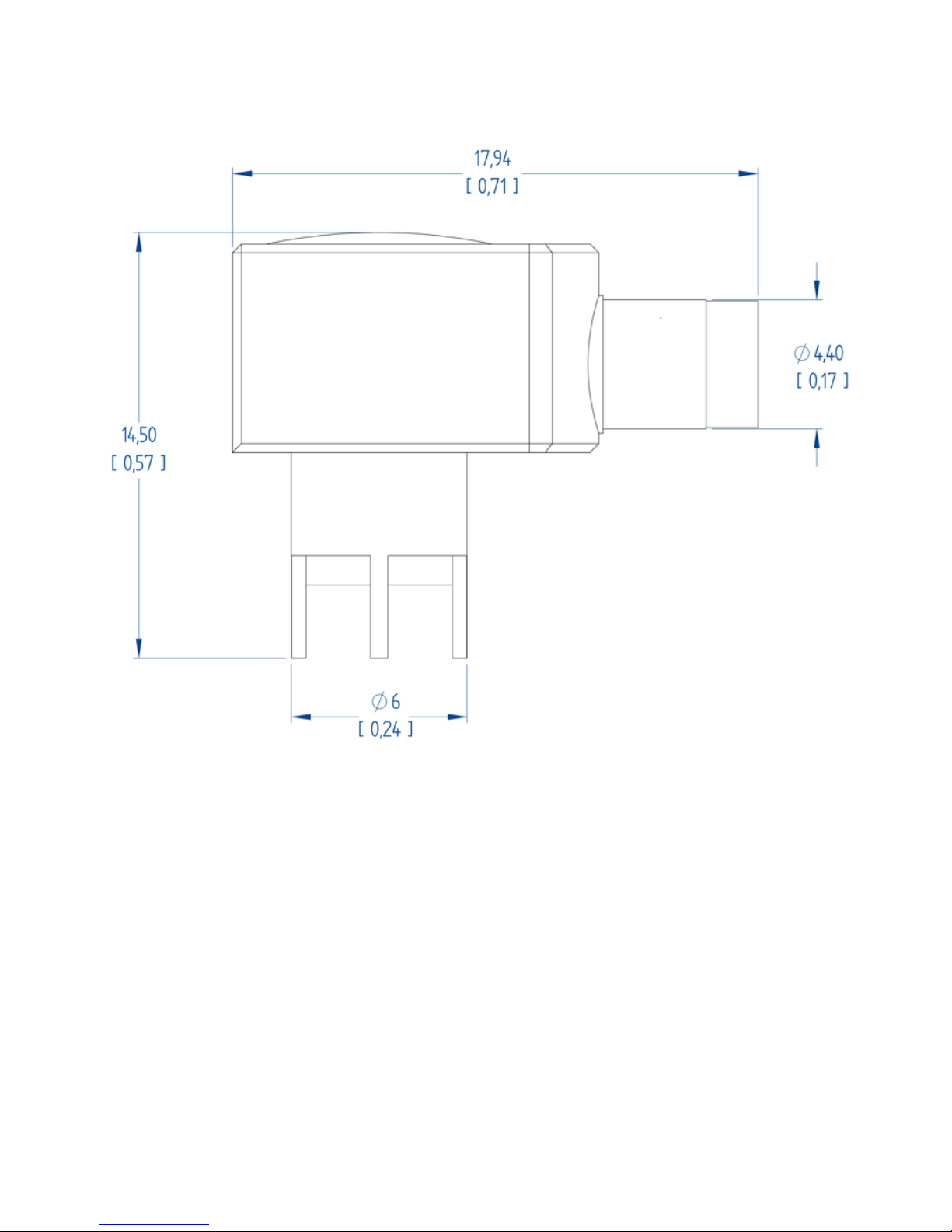
N4863A Horizontal PCB Adapter Dimensions
22
All dimensions shown in the above figure are in millimeters [inches]
Keysight N2870A-Series and N2894A Passive Probes User’s Guide
Page 23
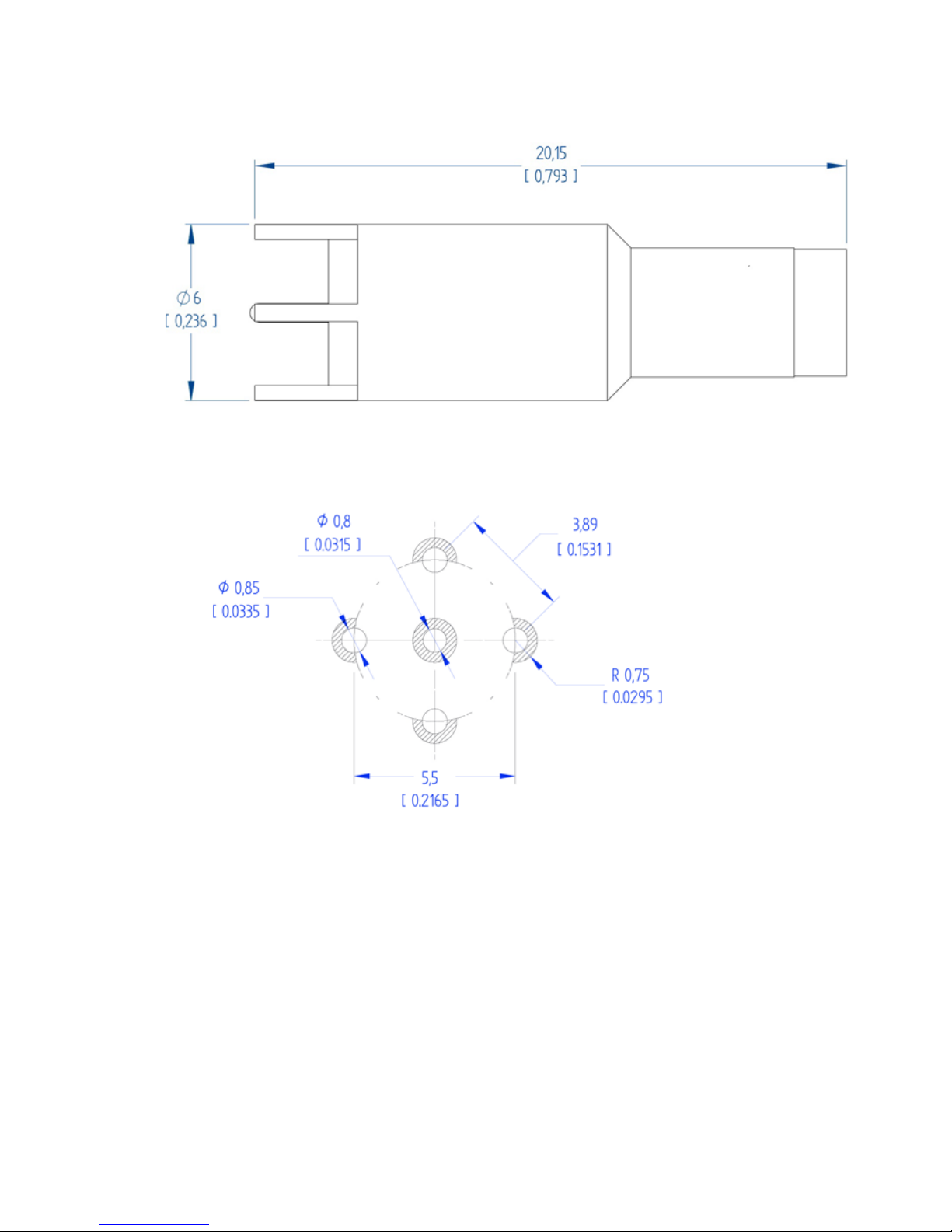
N4864A Vertical PCB Adapter Dimensions
All dimensions shown in the above figure are in millimeters [inches]
Drill and Solder Layout of N4863/4A
Available Accessories
All dimensions shown in the above figure are in millimeters [inches]
Keysight N2870A-Series and N2894A Passive Probes User’s Guide
23
Page 24
Characteristics and Specifications
Characteristics and Specifications
This section lists the characteristics and specifications for the probes. The probe
and oscilloscope should be warmed up for at least 20 minutes before any testing
and the environmental conditions should not exceed the probe’s specified limits.
Table 5 Electrical Characteristics
Description Characteristic
Attenuation ratio N2870A: 1:1
N2871A: 10:1
N2872A: 10:1
N2873A: 10:1
N2874A: 10:1
N2875A: 20:1
N2876A: 100:1
N2894A: 10:1
Bandwidth (-3 dB) N2870A: 35 MHz
N2871A: 200 MHz
N2872A: 350 MHz
N2873A: 500 MHz
N2874A: 1.5 GHz
N2875A: 500 MHz
N2876A: 1.5 GHz
N2894A: 700 MHz
a
Probe Risetime (10%-90%) N2870A: 10 ns
N2871A: 1.4 ns
N2872A: 1.0 ns
N2873A: 700 ps
N2874A: 240 ps
N2875A: 700 ps
N2876A: 240 ps
N2894A: 500 ps
Maximum Rated Input Voltage N2870A: 55 V CAT II
N2871A: 400 V CAT I
N2872A: 400 V CAT Ib, 300 V CAT II
N2873A: 400 V CAT Ib, 300 V CAT II
N2874A: 8.5 V CAT I
N2875A: 400 V CAT Ib, 300 V CAT II
N2876A: 21 V CAT I
N2894A: 400 V CAT Ib, 300 V CAT II
b
, 300 V CAT II
d
d
c
c
c
c
c
24
Keysight N2870A-Series and N2894A Passive Probes User’s Guide
Page 25

Description Characteristic
Characteristics and Specifications
Input Resistance
(scope + probe)
Input Capacitance (system) N2870A: 39 pF (+ scope)
Compensation Range N2870A: —
N2870A: 1 M
N2871A: 10 M
N2872A: 10 MΩ
N2873A: 10 MΩ
N2874A: 500 Ω
N2875A: 20 M
N2876A: 5 KΩ
N2894A: 10 MΩ
N2871A: 9.5 pF
N2872A: 9.5 pF
N2873A: 9.5 pF
N2874A: 1.8 pF
N2875A: 5.6 pF
N2876A: 2.2 pF
N2894A: 9.5 pF
N2871A: 10 - 25 pF
N2872A: 10 - 25 pF
N2873A: 10 -25 pF
N2874A: —
N2875A: 7 - 20 pF
N2876A: —
N2894A: 10 - 25 pF
Ω
Ω
Ω
Input Coupling of the Measuring Instrument N2870A: 1 MΩ
N2871A: 1 MΩ
N2872A: 1 MΩ
N2873A: 1 MΩ
N2874A: 50 Ω
N2875A: 1 MΩ
N2876A: 50 Ω
N2894A: 1 MΩ
a 700 MHz bandwidth available with InfiniiVision 4000X/6000X with 1 GHz or higher band-
width models only
b Measurement Category I, 1250 V transient overvoltage
cMeasurement Category II
d Measurement Category I, 0 V transient overvoltage
Keysight N2870A-Series and N2894A Passive Probes User’s Guide
25
Page 26

Characteristics and Specifications
WARNING
Table 6 Mechanical Characteristics
Description Characteristic
Weight (probe only) 48 g
Cable Length 1.3 m
Probe Barrel Diameter 2.5 mm
Table 7 Environmental Specifications
Description Specification
Temperature Operating: 0 °C to +50 °C
Altitude Operating: 2,000 m (6,561 ft)
Non-operating: -40 °C to +70 °C
Non-operating: 15,000 m (49,212 ft)
Humidity Operating: 80% room humidity for temperatures up to 31 °C, decreasing linearly
to 40% at 50 °C
Non-operating: 95% room humidity for temperatures up to 40 °C
Pollution Degree Pollution Degree 2
Table 8 Safety Specifications
Specification
Low Voltage Directive 2006/95/EC
CEI/IEC 61010-031:2008-08
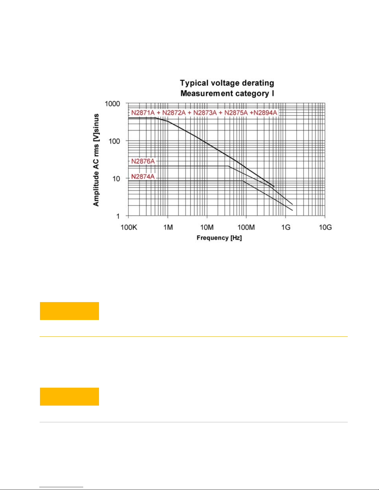
Typical Voltage Derating for Each Probe Model (Measurement Category I)
The maximum input voltage rating of the probe decreases as the
frequency of the applied signal increases.
26
Keysight N2870A-Series and N2894A Passive Probes User’s Guide
Page 27
Characteristics and Specifications
CAUTION
CAUTION
Figure 8 Typical Voltage Derating Plot
Refer to the oscilloscope documentation for the oscilloscope’s
acceptable input range and do not exceed this limit when using the
probes.
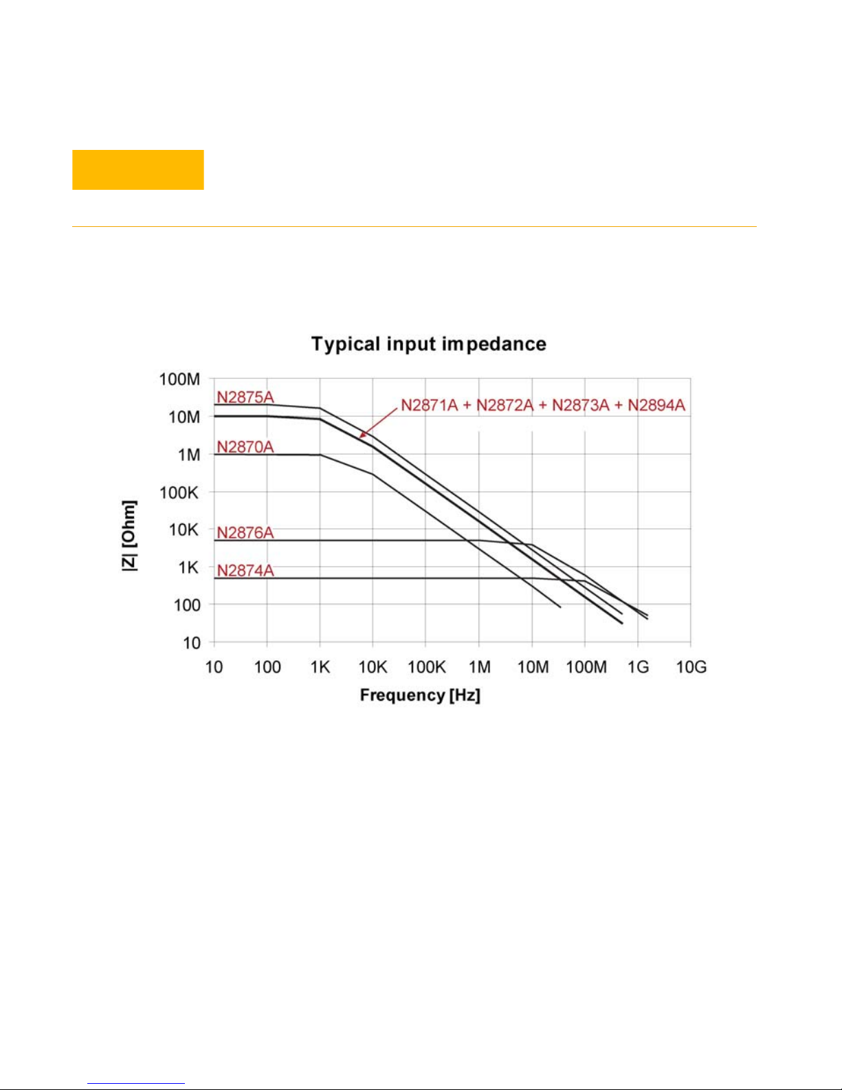
Typical Input Impedance for Each Probe Model
Refer to the oscilloscope documentation for the oscilloscope’s
acceptable input range and do not exceed this limit when using the
probes.
Keysight N2870A-Series and N2894A Passive Probes User’s Guide
27
Page 28
Characteristics and Specifications
CAUTION
The input impedance of the probe decreases as the frequency of the
applied signal increases.
Figure 9 Typical Input Impedance
28
Keysight N2870A-Series and N2894A Passive Probes User’s Guide
Page 29

Performance Verification Procedures
Performance Verification Procedures
The two procedures in this section are used to test and verify the DC attenuation
ratio and the input resistance of the probes. The recommended test interval is once
a year or as required. Use the equipment listed in Table 9 to complete the procedures.
Table 9 Required Test Equipment
Description Minimum Requirements Part Number
Digital Multimeter (DMM) 6.5 digits of resolution, resistance ± 1% Keysight 34401A
Calibrator DC Voltage 0 to ±1100 V Fluke 5700A
BNC(m) to BNC(f) 50Ω
feedthrough termination
Modified deskew and
performance verification kit, 1 MΩ ±
0.1% precision shunt
resistor is soldered between 50 Ω
trace and ground
Oscilloscope If testing N2870/1/2/3/4A or N2894A: 1 MΩ
input impedance
If testing N2874/6A: 50 Ω input impedance
Test DC Attenuation Ratio
1 Set the DMM (Keysight 34401A) to DC voltage measurement mode. Configure
the input resistance to > 10 G
Ω. Short the tip and perform the “Null” function.
Set the calibrator (Fluke 5700A) to 10V.
2 Connect the N287XA probe tip to the calibrator HI output.
3 Connect the N287XA probe ground lead to the calibrator LO output.
Keysight 11048C
Keysight E2655B
Keysight 4000-X Series
4 For models N2874A and N2876A, connect the probe output to the 50Ω
feedthrough termination (11048C). Connect the output of the 11048C to the
DMM. For all other models, connect the probe output to the modified Keysight
PV fixture 50
precision resistor. Connect the output of the 50
Keysight N2870A-Series and N2894A Passive Probes User’s Guide
Ω trace input. The trace is terminated with the 1 MΩ ± 0.1%
Ω trace to the DMM.
29
Page 30

Performance Verification Procedures
5 Verify that the measured value is between the limits listed in the table below for
each output signal. If it is then the attenuation ratio has an error within ±2%.
Table 10 Measurement Limits
Model Target Value Measured Value
N2870A x1 10V ± 200 mV
N2871A x10 1V ± 20 mV
N2872A x10 1V ± 20 mV
N2873A x10 1V ± 20 mV
N2874A x10 1V ± 20 mV
N2875A x20 500 mV ± 10 mV
N2876A x100 100 mV ± 2 mV
N2894A x10 1V ± 20 mV
Test Input Resistance
1 Turn on the DMM. Short the DMM probes and run the “Null” function.
2 Connect the DMM probes to the probe tip and the ground at the tip of the
probe.
3 Connect the probe’s output to one of the oscilloscope’s input channels. Set the
oscilloscope’s input impedance value according to the following table.
30
Keysight N2870A-Series and N2894A Passive Probes User’s Guide
Page 31

Performance Verification Procedures
Error %
Measured Value Target Value–
Target Value
-----------------------------------------------------------------------------
100×=
Table 11 Oscilloscope’s Input Impedance
Model Oscilloscope Input Impedance
N2870A 1 M
N2871A 1 MΩ
N2872A 1 MΩ
N2873A 1 MΩ
N2874A 50Ω
N2875A 1 MΩ
N2876A 50Ω
N2894A 1 MΩ
Ω
4 Set up the DMM to measure resistance. Record the resistance into the
Measured Value column in Table 12 on page 31. Calculate the Error%. It should
be less than 1%.
Table 12 DMM Measurements
Model Target Value Measured Value Error%
N2870A 1 MΩ
N2871A 10 MΩ
N2872A 10 MΩ
N2873A 10 MΩ
N2874A 500Ω
N2875A 20 MΩ
N2876A 5 kΩ
N2894A 10 MΩ
Keysight N2870A-Series and N2894A Passive Probes User’s Guide
31
Page 32

Performance Verification Test Record
Keysight Technologies N287XA/N2894A Passive Probe
Serial No.:_______________________
Test Date:_________________
Tested By:_______________________
Recommended Test Interval: 1 Year
Recommended Date of Next Test:_________
Test Temperature:_____________________
Test Probe Model Limits Results
Attenuation
Ratio
Input
Resistance
N2870A 10V ± 200 mV
N2871A 1V ± 20 mV
N2872A 1V ± 20 mV
N2873A 1V ± 20 mV
N2874A 1V ± 20 mV
N2875A 500 mV ± 10 mV
N2876A 100 mV ± 2 mV
N2894A 1V ± 20 mV
Error% < ± 1%
Page 33

IEC Measurement Category Definitions
Definitions and Examples (Clause 6.5.2).
Measurement Category I (CAT I)
Measurement category I is for measurements performed on circuits not directly
connected to a mains supply.
Example
Measurements in circuits not derived from a mains supply and specially protected
(internal) circuits derived from a mains supply. In the latter case, transient stresses
are variable. For that reason, it is required that the transient withstand capability of
the equipment is made known to the user.
Measurement Category II (CAT II)
IEC Measurement Category Definitions
Measurement category II is for measurements performed on circuits directly connected to the low voltage installation.
Example
Household appliances, portable tools, and similar equipment.
Measurement Category III (CAT III)
Measurement category III is for measurements performed in the building installation.
Example
Measurements on distribution boards, circuit breakers, wiring including cables,
bus-bars, junction boxes, switches, socket-outlets in the fixed installation and
equipment for industrial use like, for example, stationary motors with permanent
connections to the fixed installation.
Measurement Category IV (CAT IV)
Measurement category IV is for measurements performed at the source of the
low-voltage installation.
Example
Electricity meters and measurements on primary over-current protection devices
and ripple control units.
Keysight N2870A-Series and N2894A Passive Probes User’s Guide
33
Page 34

IEC Pollution Degrees Definitions
IEC Pollution Degrees Definitions
Definitions (Clause 3.5.6).
Pollution Degree 1
No POLLUTION or only dry, non-conductive POLLUTION. NOTE: The POLLUTION
has no influence.
Pollution Degree 2
Only non-conductive POLLUTION. Occasionally, however, a temporary conductivity
caused by condensation must be accepted.
Pollution Degree 3
Conductive POLLUTION occurs or dry, non-conductive POLLUTION occurs which
becomes conductive due to condensation which is to be expected.
34
Keysight N2870A-Series and N2894A Passive Probes User’s Guide
Page 35

Keysight N2870A-Series and N2894A Passive Probes User’s Guide
35
Page 36

This information is subject to
change without notice.
© Keysight Technologies 2018
October, 2018
Printed in Germany
*2876-97002*
www.keysight.com
 Loading...