

Page 1
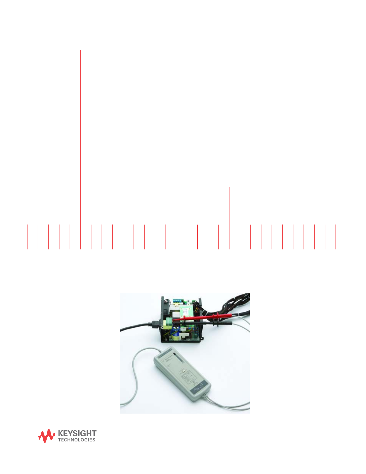
N2791A 25 MHz and
N2891A 70 MHz
High-Voltage
Differential Probes
User’s
Guide
Page 2

Contents
Inspecting the Probe 3
Cleaning the Probe 3
Handling the Probe 3
N2791A/N2891A High-Voltage Differential Probes 4
Contents and Accessory Kits 5
Characteristics 7
Safety Information 9
Using the N2791A High-Voltage Differential Probe 10
Using the N2891A High-Voltage Differential Probe 11
N2791A Plots 12
N2891A Plots 16
Using the Accessories 20
N2791A Performance Verification Procedures 21
N2791A Performance Verification Test Record 23
N2891A Performance Verification Procedures 24
N2891A Performance Verification Test Record 26
2
Page 3
Inspecting the Probe
Inspecting the Probe
❏ Inspect the shipping container for damage.
Keep the damaged shipping container or cushioning material until the contents
of the shipment have been checked for completeness and the probe has been
checked mechanically and electrically.
❏ Check the accessories.
• If the contents are incomplete or damaged, notify your Keysight Technologies
Sales Office.
❏ Inspect the instrument.
• If there is mechanical damage or defect, or if the probe does not operate
properly or pass calibration tests, notify your Keysight Technologies Sales
Office.
• If the shipping container is damaged, or the cushioning materials show signs
of stress, notify the carrier as well as your Keysight Technologies Sales Office.
Keep the shipping materials for the carrier’s inspection. The Keysight
Technologies office will arrange for repair or replacement at Keysight
Technologies’ option without waiting for claim settlement.
Cleaning the Probe
Disconnect the probe and clean it with a soft cloth. Make sure the probe is
completely dry before reconnecting it to an oscilloscope. Avoid using abrasive
cleaners and chemicals containing benzene or similar solvents.
Handling the Probe
!
Handle the probe with care and refer to the safety notices at the back of this
manual and on page 9. Note that the probe cable is a sensitive part of the probe
and, therefore, you should be careful not to damage it through excessive bending
or pulling. You should also avoid any mechanical shocks to this product in order
to guarantee accurate performance and protection.
3
Page 4
N2791A/N2891A High-Voltage Differential Probes
N2791A/N2891A High-Voltage Differential Probes
The N2791A/N2891A high-voltage differential probes allow conventional earthgrounded oscilloscopes to be used for floating signal measurements (up to 700
V of differential or common mode voltage for the N2791A and up to 7000 V of
differential or common mode voltage for the N2891A). The N2791A offers userselectable attenuation settings of 10:1 and 100:1 while the N2891A offers
attenuation settings of 100:1 and 1000:1, making both probes highly versatile
and usable for a broad range of applications including power supply
measurements and motor controls. Both probes are compatible with any
oscilloscope with a 1 MW BNC input. The probes can be powered by any USB
port on an oscilloscope or computer, or by internal batteries (4x AA included with
the probe).
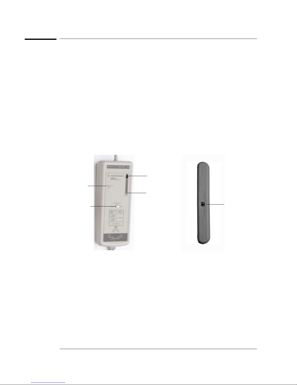
The images below show some key parts of the N2891A probe body. The N2791A
has similar switches/LEDs, but they are arranged differently.
on/off switch
overrange
indicator
attenuation
switch
Battery Use
• Insert 4 AA batteries in the back of the unit as indicated within the chassis
(see pages 10-11 for information on accessing the battery location)
• When battery life has expired, remove the batteries
• When the batteries gets close to running out, the power indicator will start
to flicker and dim
• Note the WEEE label on the batteries and dispose of properly
power LED
indicator
USB power
cord input
4
Page 5

Contents and Accessory Kits
Contents and Accessory Kits
The following table lists the parts included with the N2791A high-voltage
differential probe.
Part Quantity
N2791A 25 MHz differential probe 1
Safety Hook, Red 1
Safety Hook, Black 1
Alligator Clip, Red 1
Alligator Clip, Black 1
USB Power Cord (2 m) 1
AA Battery 4
Trimmer Tool 1
User’s Guide 1
For N2791A replacement accessories, you can order the N2791-68700
Differential Probe Accessory Kit. It includes:
Part Quantity
Safety Hook, Red 1
Safety Hook, Black 1
Alligator Clip, Red 1
Alligator Clip, Black 1
USB Power Cord (2 m) 1
5
Page 6

Contents and Accessory Kits
The following table lists the parts included with the N2891A high-voltage
differential probe.
Part Quantity
N2891A 70 MHz differential probe 1
Safety Hook, Red 1
Safety Hook, Black 1
High Voltage Alligator Clip, Red 1
High Voltage Alligator Clip, Black 1
USB Power Cord (2 m) 1
AA Battery 4
Trimmer Tool 1
User’s Guide 1
For N2891A replacement accessories, you can order the N2891-68700
Differential Probe Accessory Kit. It includes:
Part Quantity
Safety Hook, Red 1
Safety Hook, Black 1
High Voltage Alligator Clip, Red 1
High Voltage Alligator Clip, Black 1
USB Power Cord (2 m) 1
6
Page 7
Characteristics
Characteristics for the N2791A and N2891A high-voltage differential probes are
shown below. The probe / oscilloscope should be warmed up for at least 20
minutes before any testing and the environmental conditions should not exceed
the probe’s specified limits.
Electrical Characteristics
Characteristics
N2791A N2891A
Bandwidth (-3 dB) >25 MHz (driving 1 MW oscilloscope
input)
70 MHz (driving 1 MW oscilloscope
input)
Attenuation ratio 10:1, 100:1 (switchable) 100:1, 1000:1 (switchable)
Probe Risetime (10%-90%) 14 ns 5 ns
Absolute Maximum Rated
1000 Vrms CAT II 5000 Vrms CAT I
Input Voltage (each side to
ground)
Maximum Differential Input
Voltage (DC + AC Peak)
Maximum Common Mode
Input Voltage
Input Impedance 4 MW, 10 pF (each side to ground)
\70 V at 10:1 attenuation
\700 V at 100:1 attenuation
\70 V at 10:1 attenuation
\700 V at 100:1 attenuation
8 MW, 8 pF (between inputs)
\700 V at 100:1 attenuation
\7000 V at 1000:1 attenuation
\7000 V at 10:1 attenuation
\7000 V at 1000:1 attenuation
50 MW, 7 pF (each side to ground)
100 MW, 5 pF (between inputs)
Output Voltage Swing \7 V (driving 1 MW oscilloscope input) \7 V (driving 1 MW oscilloscope
input)
Offset (typical) \7.5 mV (adjustable) \5 mV (adjustable)
CMRR (typical) -80 dB at 60 Hz, -40 dB at 1 MHz -80 dB at 50 Hz, -60 dB at 20 kHz
Power Requirements 4 AA batteries or USB power adapter
(5 V/200 mA, 9 V/120 mA)
4 AA batteries or USB power adapter
(5 V/200 mA, 9 V/120 mA)
Battery Life 15 hours (alkaline battery) 11.5 hours (alkaline battery)
Battery/Power Cord The supplied voltage must be less than
12 V and greater than 4.4 V or else the
probe could be damaged
- all are typical
The supplied voltage must be less
than 12 V and greater than 4.4 V or
else the probe could be damaged
7
Page 8
Characteristics
Mechanical Characteristics
N2791A N2891A
Weight (probe only) 400 g (probe and PVC jacket) 500 g
BNC Cable Length 95 cm (37 inches) 90 cm (35 inches)
Length of Input Leads 45 cm (18 inches) 60 cm (24inches)
Dimensions (L x W x H) 170 mm x 63 mm x 21 mm
(6.7 inches x 2.5 inches x 0.83 inches)
202 mm x 83 mm x 38 mm (8.0 inches x
3.3 inches x 1.5 inches)
Environmental Specifications (same for both N2791A and N2891A)
Temperature Operating: -10 °C to +40 °C
Nonoperating: -30 °C to +70 °C
Altitude Operating: 3,000 m
Nonoperating: 15,300 m
Humidity Operating: 25 - 85% room humidity
Nonoperating: 25 - 85% room humidity
Pollution Degree Pollution Degree 2
Safety Specifications
CEI/IEC 61010-031 CAT II (N2791A)
CEI/IEC 61010-031 CAT I (N2891A)
8
Page 9
Safety Information
!
Safety Information
Warning To avoid personal injury and to prevent fire or damage to this product or products
connected to it, review and comply with the following safety precautions. Be
aware that if you use this probe assembly in a manner not specified, the protection
this product provides may be impaired.
Observe Maximum Working Voltage
To avoid injury, do not use the N2791A probe above 1000 Vrms CAT II (both 10:1
and 100:1 attenuation settings) between each input lead and earth or between
the two input leads. Do not use the N2891A probe above 5000 Vrms CAT I (1000:1
attenuation) or 500 Vrms CAT I (100:1 attenuation) between the two input leads.
Do not use the N2891A probe above 5000 Vrms CAT I (both 100:1 and 1000:1
attenuation settings) between each input lead and earth.
Must be Grounded
Before making connections to the input leads of this probe, ensure that the output
BNC connector is attached to the BNC channel input of the oscilloscope and the
oscilloscope is properly grounded.
Use Fused Test Prods if Necessary
If this probe is intended to be used with circuits of installation category II, it should
incorporate the fused test prods.
Do Not Operate Without Covers
To avoid electrical shock or fire hazard, do not operate this probe with the covers
removed.
Do Not Operate in Wet / Damp Conditions
To avoid electrical shock, do not operate this probe in wet or damp conditions.
Do Not Operate in an Explosive Atmosphere
To avoid injury or fire hazard, do not operate this probe in an explosive
atmosphere.
Avoid Exposed Circuit
To avoid injury, remove jewelry such as rings, watches, and other metallic objects.
Do not touch exposed connections and components when power is present.
9
Page 10
Using the N2791A High-Voltage Differential Probe
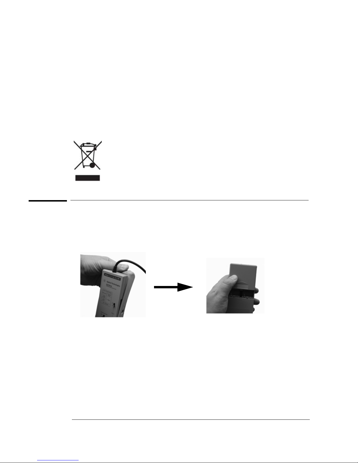
To replace batteries, first slip off
the cover
Then slide the battery cover off
on the rear of the probe
Use Proper Power Source
To ensure this probe functions well, use four AA batteries or the supplied USB
power cord.
For Indoor Use Only
Only use this probe indoors.
Do Not Operate With Suspected Failures
If you suspect there is damage to this probe, have it inspected by a qualified
service personnel.
Using the N2791A High-Voltage Differential Probe
• To use this probe, first insert the four AA batteries into the probe or connect
the USB power cord to the probe and a USB port (see page 4 to see where
the USB power cord input is located on the probe).
• Then connect the BNC output connector to the channel input of the
oscilloscope. The oscilloscope must have a ground referenced.
• Select the proper attenuation ratio (10:1 or 100:1) on the probe via the
attenuation switch and specify the attenuation and probe configuration on
your oscilloscope.
TIP: When measuring signals below 70 V, switch the attenuation ratio to 10:1
in order to obtain a higher resolution signal with less noise. Otherwise set the
attenuation ratio to 100:1.
10
Page 11
Using the N2891A High-Voltage Differential Probe
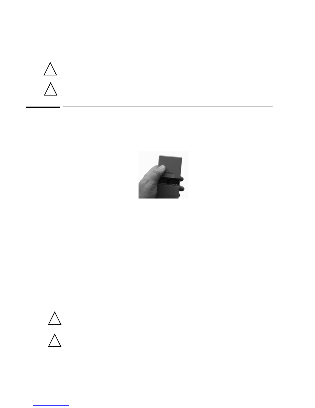
Slide the battery cover off the
rear of the probe body
Using the appropriate probe accessories, connect the inputs to the circuit
under test.
To protect against electrical shock, use only the accessories supplied with
!
!
this probe or in the accessory kit.
This probe is to carry out differential measurements between two points on
the circuit under test. This probe is not for electrically insulating the circuit
under test and the measuring instrument.
Using the N2891A High-Voltage Differential Probe
• To use this probe, first insert the four AA batteries into the probe or connect
the USB power cord to the probe and a USB port (see page 4 to see where
the USB power cord input is located on the probe).
• Then connect the BNC output connector to the channel input of the
oscilloscope. The oscilloscope must have a ground referenced.
• Select the proper attenuation ratio (100:1 or 1000:1) on the probe via the
attenuation switch (see the picture on page 4) and specify the attenuation
and probe configuration on your oscilloscope.
TIP: When measuring signals below 700 V, switch the attenuation ratio to
100:1 in order to obtain a higher resolution signal with less noise. Otherwise
set the attenuation ratio to 1000:1.
• Using the appropriate probe accessories, connect the inputs to the circuit
under test.
!
!
To protect against electrical shock, use only the accessories supplied with
this probe or in the accessory kit.
This probe is to carry out differential measurements between two points on
the circuit under test. This probe is not for electrically insulating the circuit
under test and the measuring instrument.
11
Page 12
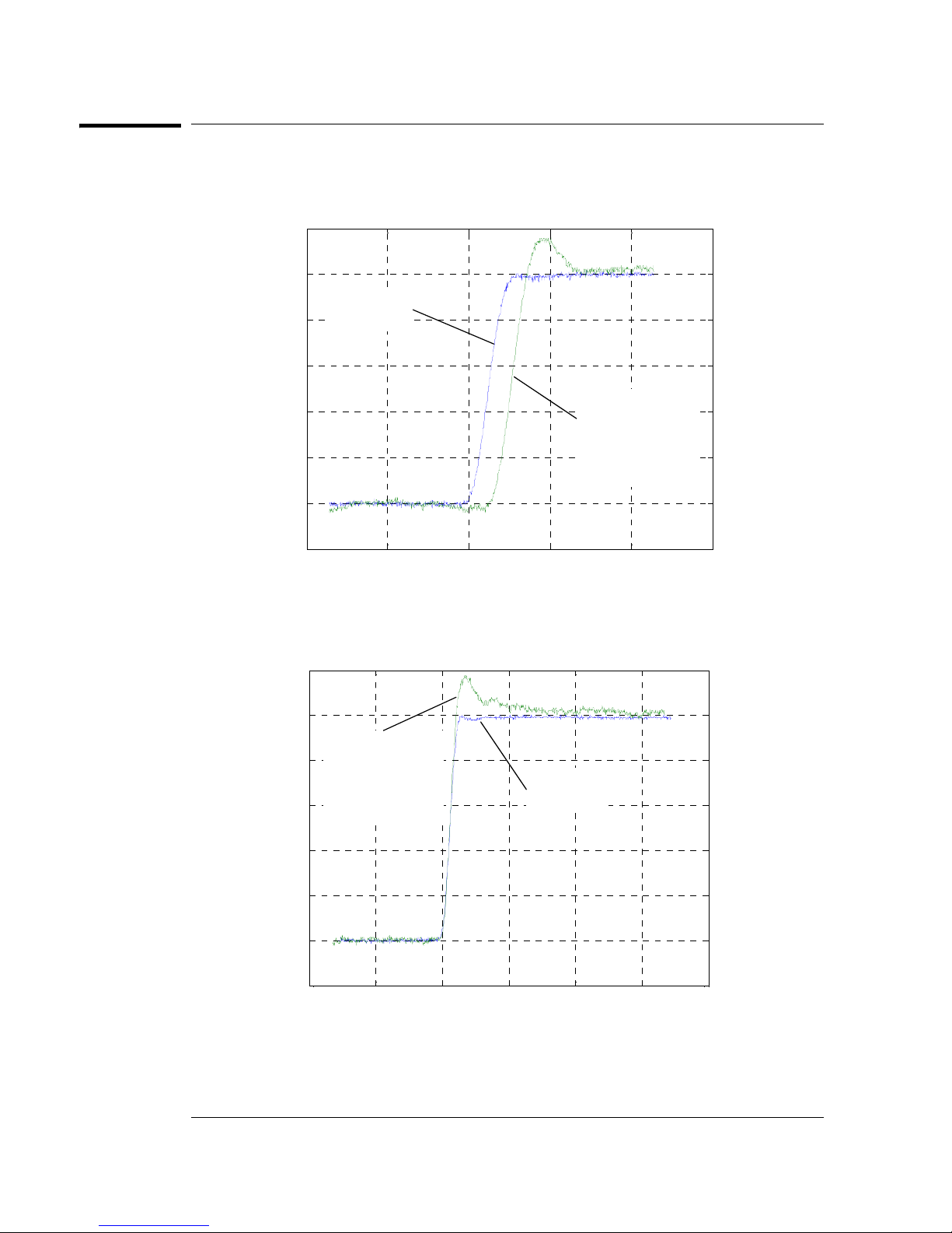
N2791A Plots
-100 -50 0 50 100 150
-0.2
0
0.2
0.4
0.6
0.8
1
1.2
Time (ns)
Volts
Step Input
Signal
Measured Step
Response
(17 ns 10-90%
rise time)
-100 0 100 200 300 400 500
-0.2
0
0.2
0.4
0.6
0.8
1
1.2
Time (ns)
Volts
Step Input
Signal
Measured Step
Response
(17 ns 10-90%
rise time)
N2791A Plots
Graph of normalized step response (50Ω, 16.5 ns rising edge step generator), 17
ns normalized rising edge (10-90%), 10:1 attenuation
Graph of normalized step response (50Ω, 17 ns rising edge step generator), 17
ns normalized rising edge (10-90%), 100:1 attenuation
12
Page 13
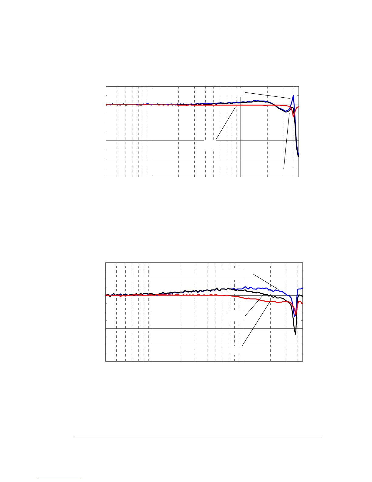
N2791A Plots
10
0
10
1
-20
-15
-10
-5
0
5
Fre q uency (MHz )
dB
Vout
Vin
Vout/Vin
10
0
10
1
-10
-7.5
-5
-2.5
0
2.5
5
F re quency (MHz)
dB
Vout/Vin
Vout
Vin
Graph of dB(Vin), dB(Vout) + 20dB, and dB(Vout/Vin) + 20dB frequency response,
10:1 attenuation
Graph of dB(Vin), dB(Vout) + 40dB, and dB(Vout/Vin) + 40dB frequency response,
100:1 attenuation
13
Page 14
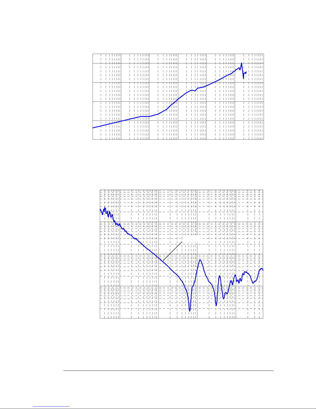
N2791A Plots
10
2
10
3
10
4
10
5
10
6
10
7
10
8
-100
-80
-60
-40
-20
F re quency (H z)
dB
10
6
10
7
10
8
10
9
10
2
10
3
10
4
10
5
Frequency (Hz )
Ω
22 pF
Graph of dB(Vout/Vin) + 20dB frequency response when inputs driven in common
mode (common mode rejection), 10:1 attenuation
Magnitude plot of probe input impedance versus frequency (single-ended mode)
14
Page 15
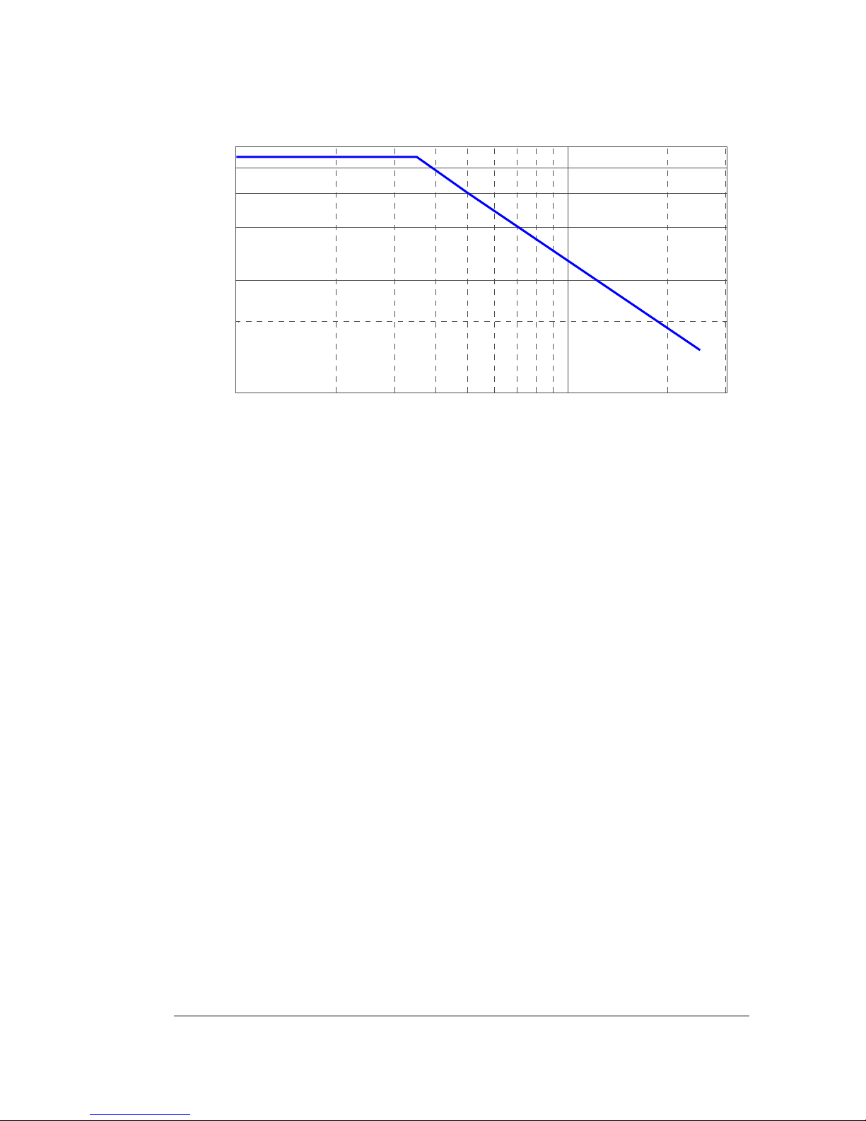
N2791A Plots
10
6
10
7
100
300
500
700
900
1100
Freque ncy (H z)
Vrms
Typical derating plot of the absolute maximum input voltage in common mode
15
Page 16
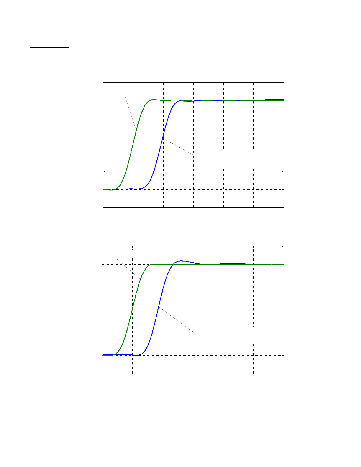
N2891A Plots
-20 0 20 40 60 80 100
-0.2
0
0.2
0.4
0.6
0.8
1
1.2
Time (nS)
Normaliz ed S tep Response (V)
Step Input Signal
Probe Step Response
(10 ns 10-90% rise time)
-20 0 20 40 60 80 100
-0.2
0
0.2
0.4
0.6
0.8
1
1.2
Time ( nS )
Normaliz ed S t ep Res pons e (V )
Step Input Signal
Probe Step Response
(10 ns 10-90% rise time)
N2891A Plots
Graph of normalized step response (50 W, 10 ns rising edge step generator), 10
ns normalized rising edge (10-90%), 100:1 attenuation
Graph of normalized step response (50 W, 10 ns rising edge step generator), 10
ns normalized rising edge (10-90%), 1000:1 attenuation
16
Page 17
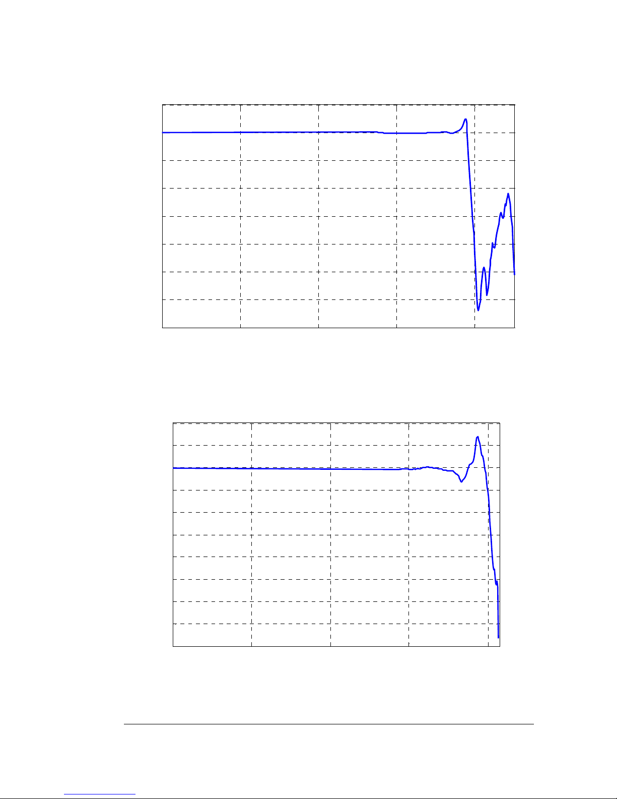
N2891A Plots
10
0
10
2
10
4
10
6
10
8
-35
-30
-25
-20
-15
-10
-5
0
5
Frequency Hz
Normalized S21+40dB
10
0
10
2
10
4
10
6
10
8
-16
-14
-12
-10
-8
-6
-4
-2
0
2
4
Frequenc y Hz
Normali zed S21+60dB
Graph of dB (S21) + 40 dB frequency response, 100:1 attenuation
Graph of dB (S21) + 60 dB frequency response, 1000:1 attenuation
17
Page 18
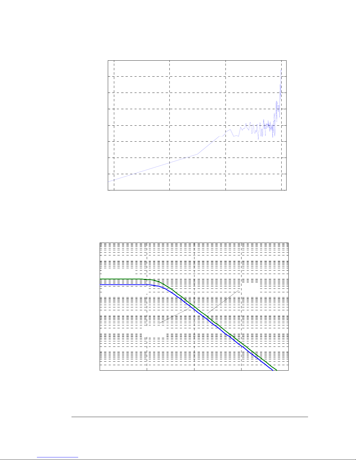
N2891A Plots
10
2
10
4
10
6
10
8
-90
-80
-70
-60
-50
-40
-30
-20
-10
Frequenc y (Hz)
CMRR dB
10
0
10
2
10
4
10
6
10
8
10
3
10
4
10
5
10
6
10
7
10
8
10
9
10
10
Frequency (Hz)
Input i m pedance (Ohms )
5 pF
7.2 pF
differential
single-ended
Graph of dB (S21) + 40 dB frequency response when inputs driven in common
mode (common mode rejection), 100:1 attenuation
Magnitude plot of probe input impedance versus frequency, single-ended and
differential
18
Page 19
N2891A Plots
10
5
10
6
10
7
10
8
10
1
10
2
10
3
10
4
Frequ ency (H z)
Vrms
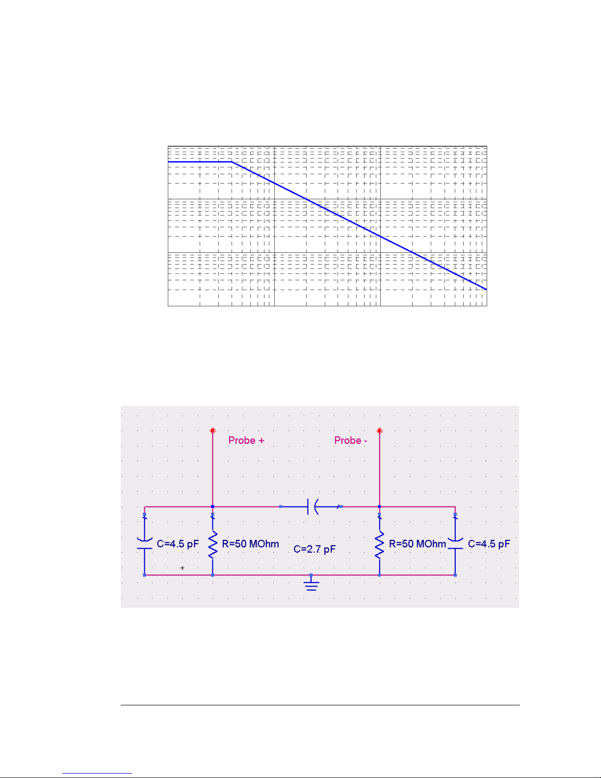
Typical derating plot of the absolute maximum input voltage in common mode
Input impedance equivalent circuit diagram
19
Page 20
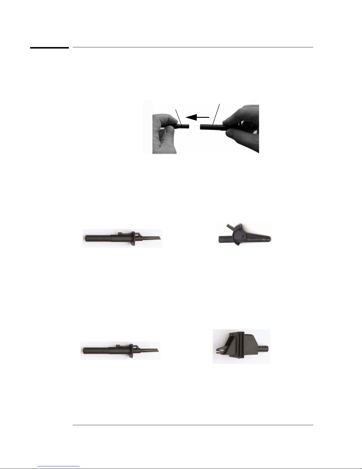
Using the Accessories
hook or clip
probe lead
Using the Accessories
The accessories supplied with the N2791A and N2891A probes are attached by
pushing them onto the probe leads as shown below.
The following accessories are supplied with the N2791A probe and with the
N2791-68700 Accessory Kit.
Safety Hook and Alligator Clips
Use the safety hooks to clamp onto smaller components and use the alligator
clips to clamp onto thicker gauge devices
safety hook
The following accessories are supplied with the N2891A probe and with the
N2891-68700 Accessory Kit.
Safety Hook and High-Voltage Alligator Clips
Use the safety hooks to clamp onto smaller components and use the alligator
clips to clamp onto thicker gauge devices
safety hook
high-voltage alligator clip
alligator clip
20
Page 21

N2791A Performance Verification Procedures
N2791A Performance Verification Procedures
The following procedure can be used to test the DC differential gain accuracy
and bandwidth of the N2791A differential probe. Please note that these
procedures do not indicate that these characteristics are warranted. Instead,
these procedures are meant to give you an idea of how your probe performs.
Required Test Equipment
Description Critical Specifications
Digitizing Oscilloscope Bandwidth: >50 MHz
1 MΩ/50Ω selectable input
Signal Generator
Precision DC voltage
source
BNC Adapter BNC (f) to Dual Banana (m)
50 Ω BNC Feed Through
Adapter
DC Differential Gain Accuracy
1 Set the volts/division on channel 1 of the oscilloscope to 20 mV/div. Set the
seconds/div to 200 μs and the acquisition mode to average 64.
2 Set the volts/division on channel 2 of the oscilloscope to 500 mV/div. Trigger on
channel 2, select 50 Ω impedance.
3 Set the calibrator 9500B’s channel 2 as the trigger channel (50 Ω load). Connect
the calibrator’s channel 2 active head to channel 2 of the oscilloscope.
4 Connect the active head channel 1 from the Fluke 9500B to channel 1 of the
oscilloscope. Set the calibrator channel 1 to 0.1V peak-to-peak amplitude and
1 KHz (square wave, 1 MΩ load), enable the output.
5 Select the amplitude measurement on the oscilloscope and record the DC
amplitude (approximately 100 mV) of the square wave. This measurement is only
the oscilloscope.
6 Disable the Fluke calibrator output, disconnect the channel 1 active head from
channel 1 of the oscilloscope.
7 Connect the output of the N2791A probe to channel 1 of the oscilloscope.
8 Attach the BNC adapter to the Fluke channel 1 active head.
Amplitude accuracy: less than
or equal to 0.25%
1 MΩ/50Ω selectable load
Sine wave greater than or
equal to 25 MHz
Adapter
50 Ω precision feed through Keysight 11048C Termination between
Recommended Model
Part Number
Keysight MSO9254A Display probe output
Fluke 9500B Signal source for DC gain
and bandwidth
Keysight 1251-2277 Interconnection between
probe and generator
probe and calibrator for
bandwidth verification
Functions
21
Page 22

N2791A Performance Verification Procedures
9 Attach the differential probe input leads by clipping the alligator clamp to the
BNC adapter banana post.
10 Set the probe to 100:1. Set the Fluke calibrator to 10 V and 1 KHz standard
amplitude output (channel 1, square wave, 1 MΩ load).
11 Enable the output of the calibrator.
12 Record the DC amplitude of the square wave and divide 100 into just the
amplitude of the oscilloscope. Verify that the probe gain accuracy is +/-2% +
scope gain accuracy.
13 Set the calibrator to 1 V output and set the attenuation button on the probe to
10:1.
14 Record the DC amplitude of the square wave and divide 10 into just the amplitude
of the oscilloscope. Verify that the probe gain accuracy is +/-2% + scope gain
accuracy.
15 Disable the calibrator output and leave the setup connected for the next
procedure.
Bandwidth
1 Connect the 50 Ω BNC feed through adapter to the calibrator’s active head
channel 1.
2 Attach the BNC (f)-to-banana post adapter to the BNC feed through adapter.
3 Attach the differential probe input leads by clipping the alligator clamp to the
BNC adapter banana post.
4 Set the probe to 10:1 attenuation.
5 Set the volts/division on channel 1 of the oscilloscope to 50 mV/div and seconds/
division to 50 ns/div. Set the trace to the center of the oscilloscope. Input
impedance should be set to 1 ΜΩ. Set the average mode to 16 points.
6 Set the calibrator to sine wave, 3 V peak-to-peak amplitude. Set the frequency
to 25 MHz, 50 Ω load.
7 Write down the peak-to-peak amplitude measured by the oscilloscope. It should
be greater than or equal to 210 mV - scope vertical accuracy.
8 Disable the generator output and disconnect the probe input.
22
Page 23
N2791A Performance Verification Test Record
N2791A Performance Verification Test Record
Keysight Technologies
Recommended Test Interval: 1 Year
Recommended Date of Next Certification:_________
Certification Temperature:_____________________
Test Probe Settings Limits Results
Gain 100:1 98 mV to 102 mV
Gain 10:1 98 mV to 102 mV
Bandwidth 10:1 Greater than or equal to 210 mV - scope
vertical accuracy
N2791A 25 MHz Differential Probe
Serial No.:________________________
Certification Date:________________
Tested By:_______________________
_________________________________
_________________________________
23
Page 24

N2891A Performance Verification Procedures
N2891A Performance Verification Procedures
The following procedure can be used to test and verify the DC differential gain
accuracy and bandwidth of the N2891A high voltage differential probe. Please
note that these procedures do not indicate that these characteristics are
warranted. Instead, these procedures are meant to give you an idea of how your
probe performs.
Required Test Equipment
Description Critical Specifications
Digitizing Oscilloscope Bandwidth: >50 MHz
1 MΩ/50Ω selectable input
Signal Generator
Precision DC voltage
source
BNC Adapter BNC (f) to Dual Banana (m)
50 Ω BNC Feed Through
Adapter
DC Differential Gain Accuracy
Amplitude accuracy: less than
or equal to 0.25%
1 MΩ/50Ω selectable load
Sine wave greater than or
equal to 25 MHz
Adapter
50 Ω precision feed through Keysight 11048C Termination
Recommended Model
Part Number
Keysight MSO9254A Display probe output
Fluke 9500B Signal source for DC
Keysight 1251-2277 Interconnection
Functions
gain and bandwidth
between probe and
generator
between probe and
calibrator for
bandwidth
verification
WARNING: Generator produces hazardous voltages. To avoid shock, do not touch exposed
metal parts after generator output is enabled.
WARNING: These procedures require the application of high voltage to the inputs of the
N2891A probe. Because this adapter has exposed metal surfaces, only qualified personnel
should perform any testing with voltage levels exceeding 30 Vrms. All pertinent safety
rules and guidelines for elevated voltage measurements should be followed and adhered
to.
1 Set the volts/division on channel 1 of the oscilloscope to 20 mV/div. Set the
seconds/div to 200 μs and the acquisition mode to average 32.
24
Page 25

N2891A Performance Verification Procedures
2 Set the volts/division on channel 2 of the oscilloscope to 500 mV/div. Trigger on
channel 2, select 50 Ω impedance.
3 Set the calibrator 9500B’s channel 2 as the trigger channel (50 Ω load). Connect
the calibrator’s channel 2 active head to channel 2 of the oscilloscope.
4 Connect the active head channel 1 from the Fluke 9500B to channel 1 of the
oscilloscope. Set the calibrator channel 1 to 0.1V peak-to-peak amplitude and
1 KHz (square wave, 1 MΩ load), enable the output.
5 Select the amplitude measurement on the oscilloscope and record the DC
amplitude (approximately 100 mV) of the square wave. This measurement is only
the oscilloscope.
6 Disable the Fluke calibrator output, disconnect the channel 1 active head from
channel 1 of the oscilloscope.
7 Connect the output of the N2891A probe to channel 1 of the oscilloscope.
8 Attach the BNC adapter to the Fluke channel 1 active head.
9 Attach the differential probe input leads by clipping the alligator clamp to the
BNC adapter banana post.
10 Set the probe to 100:1. Set the Fluke calibrator to 10 V and 1 KHz standard
amplitude output (channel 1, square wave, 1 MΩ load).
11 Enable the output of the calibrator.
12 Record the DC amplitude of the square wave and divide 100 into just the
amplitude of the oscilloscope. Verify that the probe gain accuracy is +/-2% +
scope gain accuracy.
13 Set the calibrator to 100 V output and set the attenuation button on the probe
to 1000:1.
14 Record the DC amplitude of the square wave and divide 10 into just the amplitude
of the oscilloscope. Verify that the probe gain accuracy is +/-2% + scope gain
accuracy.
15 Disable the calibrator output and leave the setup connected for the next
procedure.
Bandwidth
1 Connect the 50 Ω BNC feed through adapter to the calibrator’s active head
channel 1.
2 Attach the BNC (f)-to-banana post adapter to the BNC feed through adapter.
3 Attach the differential probe input leads by clipping the alligator clamp to the
BNC adapter banana post.
4 Set the probe to 100:1 attenuation.
5 Set the volts/division on channel 1 of the oscilloscope to 10 mV/div and seconds/
division to 20 ns/div. Set the trace to the center of the oscilloscope. Input
impedance should be set to 1 ΜΩ. Disable average mode.
6 Set the calibrator to sine wave, 5 V peak-to-peak amplitude. Set the frequency
to 70 MHz, 50 Ω load.
7 Write down the peak-to-peak amplitude measured by the oscilloscope. It should
be greater than or equal to 35 mV - scope vertical accuracy.
8 Disable the generator output and disconnect the probe input.
25
Page 26
N2891A Performance Verification Test Record
N2891A Performance Verification Test Record
Keysight Technologies
Recommended Test Interval: 1 Year
Recommended Date of Next Certification:_________
Certification Temperature:_____________________
Test Probe Settings Limits Results
Gain 100:1 98 mV to 102 mV
Gain 1000:1 98 mV to 102 mV
Bandwidth 100:1 Greater than or equal to 35 mV - scope
vertical accuracy
N2891A 70 MHz Differential Probe
Serial No.:_______________________
Certification Date:________________
Tested By:_______________________
_________________________________
_________________________________
26
Page 27
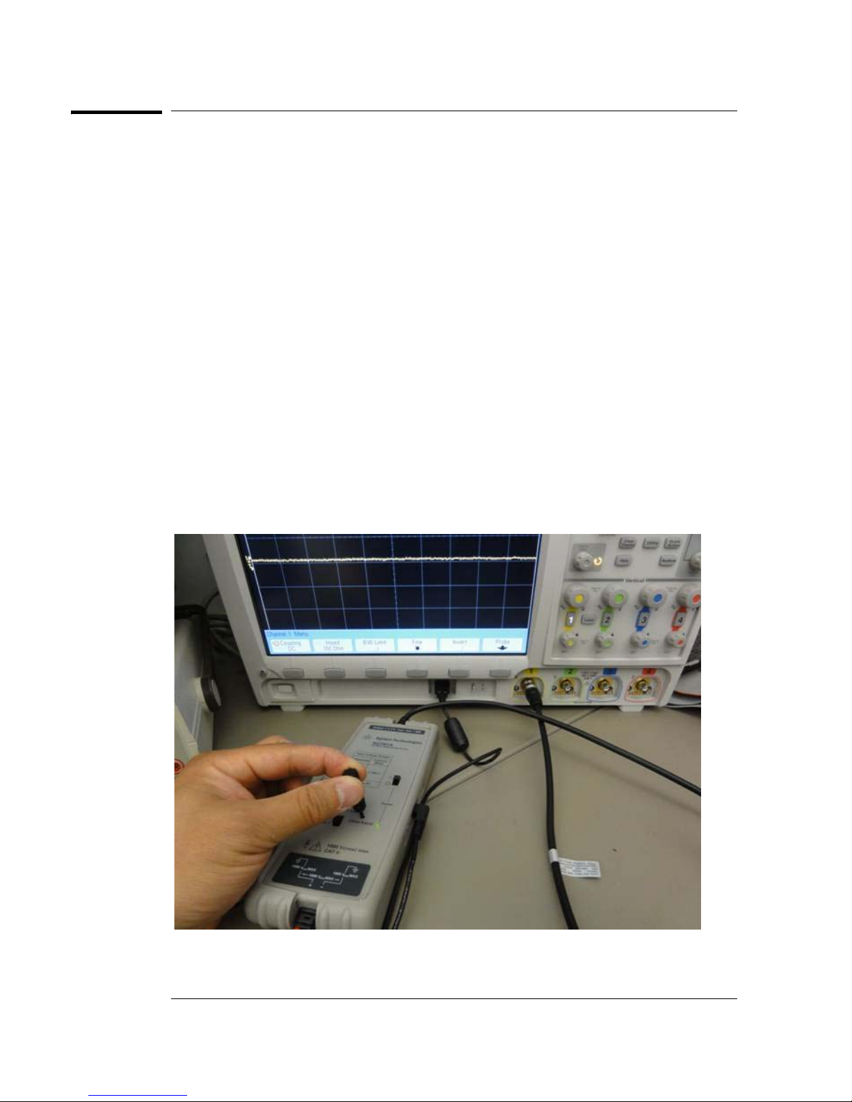
Offset Zero Calibration Procedure
Offset Zero Calibration Procedure
The N2791A/N2891A differential probe can be adjusted for zeroing out the
probe’s offset voltage using the trimmer tool supplied with the probe. Follow this
procedure to perform the offset zero calibration.
1 Connect the N2791A/N2891A probe to channel 1 of the scope. Turn on the probe
power. You may use the USB power code or batteries to power the probe. Select
the probe attenuation ratio to 10:1 (for N2791A) or 100:1 (for N2891A).
2 Short the + and - probe inputs together with the hook tips.
3 Turn on power to the oscilloscope and the probe, and leave them on for > 30
minutes so they can stabilize.
4Press [Default Setup] and [Auto Scale] on the oscilloscope.
5 Press the channel 1 button, then press the Probe softkey, and then set the units
to Volt and the probe attenuation to 10:1 (for N2791A) or 100:1 (for N2891A).
6 Set the scope to DC coupled mode and the scope offset to 0 Volt.
7 Set the oscilloscope to Averaging mode (x8 or higher) or high-resolution mode
to reduce oscilloscope noise.
8 Using the trimmer tool that comes with the probe, adjust the probe offset voltage
to 0 volts.
27
Page 28

Offset Zero Calibration Procedure
28
Page 29
Safety
!
Notices
This apparatus has been
designed and tested in accor
dance with IEC Publication
61010, Safety Requirements
for Measuring Apparatus, and
has been supplied in a safe
condition. This is a Safety Class
I instrument (provided with ter
minal for protective earthing).
Before applying power, verify
that the correct safety precau
tions are taken (see the following warnings). In addition, note
the external markings on the
instrument that are described
under "Safety Symbols."
Warnings
• Whenever it is likely that the
ground protection is impaired,
you must make the instrument
inoperative and secure it
against any unintended opera
tion.
• Service instructions are for
trained service personnel. To
avoid dangerous electric shock,
do not perform any service
unless qualified to do so. Do
not attempt internal service or
adjustment unless another per
son, capable of rendering first
aid and resuscitation, is pres
ent.
• Do not install substitute parts
or perform any unauthorized
modification to the instrument.
• Capacitors inside the instrument may retain a charge even
if the instrument is discon
nected from its source of supply.
• Do not operate the instrument in the presence of flammable gasses or fumes.
Operation of any electrical
instrument in such an environ
ment constitutes a definite
safety hazard.
• Do not use the instrument in a
manner not specified by the
manufacturer.
-
-
-
-
-
-
Safety Symbols
Instruction manual symbol: the
product is marked with this
symbol when it is necessary for
you to refer to the instruction
manual in order to protect
against damage to the product
or personal injury.
-
Hazardous voltage symbol.
-
Keysight Technologies
1900 Garden of the Gods Road
Colorado Springs, CO 80901
Page 30
Notices
© Keysight Technologies, Inc.
2009-2014
No part of this manual may be
reproduced in any form or by any
means (including electronic stor
age and retrieval or translation
into a foreign language) without
prior agreement and written con
sent from Keysight Technologies,
Inc. as governed by United States
and international copyright laws.
Manual Part Number
N2791-97003, Aug 2014
Print History
N2791-97002, Feb 2011
N2791-97001, Nov 2009
N2791-97000, May 2009
Keysight Technologies, Inc.
1900 Garden of the Gods Road
Colorado Springs, CO 80907 USA
Restricted Rights Legend
If software is for use in the per-
formance of a U.S. Government
prime contract or subcontract,
Software is delivered and
licensed as “Commercial com
puter software” as defined in
DFAR 252.227-7014 (June
1995), or as a “commercial item”
as defined in FAR 2.101(a) or as
“Restricted computer software”
as defined in FAR 52.227-19
(June 1987) or any equivalent
agency regulation or contract
clause. Use, duplication or disclo
sure of Software is subject to
Keysight Technologies’ standard
commercial license terms, and
non-DOD Departments and Agen
cies of the U.S. Government will
receive no greater than
Restricted Rights as defined in
FAR 52.227-19(c)(1-2) (June
1987). U.S. Government users
will receive no greater than Lim
ited Rights as defined in FAR
52.227-14 (June 1987) or DFAR
252.227-7015 (b)(2) (November
1995), as applicable in any tech
nical data.
-
-
ity and fitness for a particular purpose. Keysight shall
not be liable for errors or for
incidental or consequential
damages in connection with
the furnishing, use, or perfor
mance of this document or of
-
any information contained
herein. Should Keysight and
the user have a separate
-
written agreement with war
ranty terms covering the
material in this document
that conflict with these
terms, the warranty terms in
the separate agreement shall
control.
Technology Licenses
The hardware and/or software
described in this document are
furnished under a license and
may be used or copied only in
accordance with the terms of
such license.
-
-
-
WARNING
A WARNING notice
denotes a hazard. It calls
attention to an operating
-
procedure, practice, or
the like that, if not
correctly performed or
adhered to, could result in
-
personal injury or death.
Do not proceed beyond a
WARNING notice until the
indicated conditions are
fully understood and met.
CAUTION
A CAUTION notice
denotes a hazard. It calls
attention to an operating
procedure, practice, or
the like that, if not
correctly performed or
adhered to, could result in
damage to the product or
loss of important data. Do
not proceed beyond a
CAUTION notice until the
indicated conditions are
fully understood and met.
Document Warranty
The material contained in this
document is provided “as is,”
and is subject to being
changed, without notice, in
future editions. Further, to
the maximum extent permit
ted by applicable law, Keysight disclaims all
warranties, either express or
implied, with regard to this
manual and any information
contained herein, including
but not limited to the implied
warranties of merchantabil
-
Page 31

Page 32

Keysight Technologies, Printed in the Philippines August 2014
Manual Part Number: N2791-97003
*N2791-97003*
 Loading...