

Page 1
Keysight N2790A
Differential Voltage
Probe
User Guide
Page 2

Notices
CAUTION
WARNING
© Keysight Technologies 2013 - 2014,
2015, 2018
No part of this manual may be reproduced
in any form or by any means (including
electronic storage and retrieval or translation into a foreign language) without prior
agreement and written consent from
Keysight Technologies as governed by
United States and international copyright
laws.
Manual Part Number
N2790-97005
Edition
Edition 4, September 2018
Available in electronic format only
Warranty
THE MATERIAL CONTAINED IN THIS
DOCUMENT IS PROVIDED "AS IS," AND IS
SUBJECT TO BEING CHANGED, WITHOUT
NOTICE, IN FUTURE EDITIONS. FURTHER,
TO THE MAXIMUM EXTENT PERMITTED BY
APPLICABLE LAW, KEYSIGHT DISCLAIMS
ALL WARRANTIES, EITHER EXPRESS OR
IMPLIED WITH REGARD TO THIS MANUAL
AND ANY INFORMATION CONTAINED
HEREIN, INCLUDING BUT NOT LIMITED TO
THE IMPLIED WARRANTIES OF
MERCHANTABILITY AND FITNESS FOR A
PARTICULAR PURPOSE. KEYSIGHT SHALL
NOT BE LIABLE FOR ERRORS OR FOR
INCIDENTAL OR CONSEQUENTIAL
DAMAGES IN CONNECTION WITH THE
FURNISHING, USE, OR PERFORMANCE OF
THIS DOCUMENT OR ANY INFORMATION
CONTAINED HEREIN. SHOULD KEYSIGHT
AND THE USER HAVE A SEPARATE
WRITTEN AGREEMENT WITH WARRANTY
TERMS COVERING THE MATERIAL IN THIS
DOCUMENT THAT CONFLICT WITH THESE
TERMS, THE WARRANTY TERMS IN THE
SEPARATE AGREEMENT WILL CONTROL.
Technology Licenses
The hardware and/or software described in
this document are furnished under a
license and may be used or copied only in
accordance with the terms of such license.
U.S. Government Rights
The Software is "commercial computer
software," as defined by Federal Acquisition
Regulation ("FAR") 2.101. Pursuant to FAR
12.212 and 27.405-3 and Department of
Defense FAR Supplement ("DFARS")
227.7202, the U.S. government acquires
commercial computer software under the
same terms by which the software is customarily provided to the public. Accordingly, Keysight provides the Software to
U.S. government customers under its standard commercial license, which is embodied in its End User License Agreement
(EULA), a copy of which can be found at
http://www.keysight.com/find/sweula. The
license set forth in the EULA represents the
exclusive authority by which the U.S. government may use, modify, distribute, or
disclose the Software. The EULA and the
license set forth therein, does not require
or permit, among other things, that Keysight: (1) Furnish technical information
related to commercial computer software
or commercial computer software documentation that is not customarily provided
to the public; or (2) Relinquish to, or otherwise provide, the government rights in
excess of these rights customarily provided
to the public to use, modify, reproduce,
release, perform, display, or disclose commercial computer software or commercial
computer software documentation. No
additional government requirements
beyond those set forth in the EULA shall
apply, except to the extent that those
terms, rights, or licenses are explicitly
required from all providers of commercial
computer software pursuant to the FAR and
the DFARS and are set forth specifically in
writing elsewhere in the EULA. Keysight
shall be under no obligation to update,
revise or otherwise modify the Software.
With respect to any technical data as
defined by FAR 2.101, pursuant to FAR
12.211 and 27.404.2 and DFARS 227.7102,
the U.S. government acquires no greater
than Limited Rights as defined in FAR
27.401 or DFAR 227.7103-5 (c), as applicable in any technical data. 52.227-14
(June 1987) or DFAR 252.227-7015 (b)(2)
(November 1995), as applicable in any
technical data.
Safety Notices
A CAUTION notice denotes a hazard.
It calls attention to an operating procedure, practice, or the like that, if
not correctly performed or adhered
to, could result in damage to the
product or loss of important data. Do
not proceed beyond a CAUTION
notice until the indicated conditions
are fully understood and met.
A WARNING notice denotes a hazard.
It calls attention to an operating procedure, practice, or the like that, if
not correctly performed or adhered
to, could result in personal injury or
death. Do not proceed beyond a
WARNING notice until the indicated
conditions are fully understood and
met.
2 Keysight N2790A Differential Voltage Probe User Guide
Page 3

Contents
Introduction 5
Compatibility 5
Inspecting the Probe 5
Supplied Accessories 6
Optional Accessories 7
Cleaning the Probe 8
Safety Information 9
Using the Probe 13
Using the Supplied Accessories 13
Using the Optional Accessories 13
Selecting the Correct Attenuation on the Probe and the
Oscilloscope
Adjusting the Probe Offset Level 17
17
Characteristics and Specifications 18
Characterization Plots 21
Performance Verification Procedures 23
DC Differential Gain Accuracy 24
Bandwidth 25
Performance Verification Test Record 25
Service 26
Keysight N2790A Differential Voltage Probe User Guide 3
Page 4

Contents
4 Keysight N2790A Differential Voltage Probe User Guide
Page 5

Introduction
Compatibility
Keysight N2790A Differential Voltage Probe
User Guide
The N2790A differential probe allows you to safely measure high-voltage
floating circuits with the oscilloscope grounded. It is ideal for many
applications such as motor speed controls, power supply designs, and
electronic high-power converters. The N2790A offers sufficient dynamic
range and bandwidth for your application to make the floating
measurements found in high-speed power electronic circuits safely and
accurately.
With 100 MHz bandwidth, switchable attenuation of 50:1 and 500:1, and a
maximum differential voltage input of 1400V (DC + peak AC), it provides
the versatility for a broad range of applications including high-voltage
circuits. The probe is powered by the auto-probe interface.
The N2790A differential probe is compatible with the following Keysight
oscilloscopes:
• InfiniiVision Series 5000, 6000 (except 100 MHz), and 7000 with version
5.2 software or later
• Infiniium 9000 (with version 2.00 software or later), 8000 (with version
5.61 software or later), and 54830 Series (with version 5.61 software or
later)
Inspecting the Probe
• Inspect the shipping container for damage.
Keep the damaged shipping container or cushioning material until the
contents of the shipment have been checked for completeness and the
probe has been checked mechanically and electrically.
• Check the accessories.
If the contents are incomplete or damaged, notify your Keysight
Technologies Sales Office.
• Inspect the instrument.
If there is mechanical damage or defect, or if the probe does not
operate properly or pass calibration tests, notify your Keysight
Technologies Sales Office.
Page 6
Introduction
If the shipping container is damaged, or the cushioning materials show
signs of stress, notify the carrier as well as your Keysight Technologies,
Sales Office. Keep the shipping materials for the carrier’s inspection.
The Keysight Technologies office will arrange for repair or replacement
option at Keysight Technologies without waiting for claim settlement.
Supplied Accessories
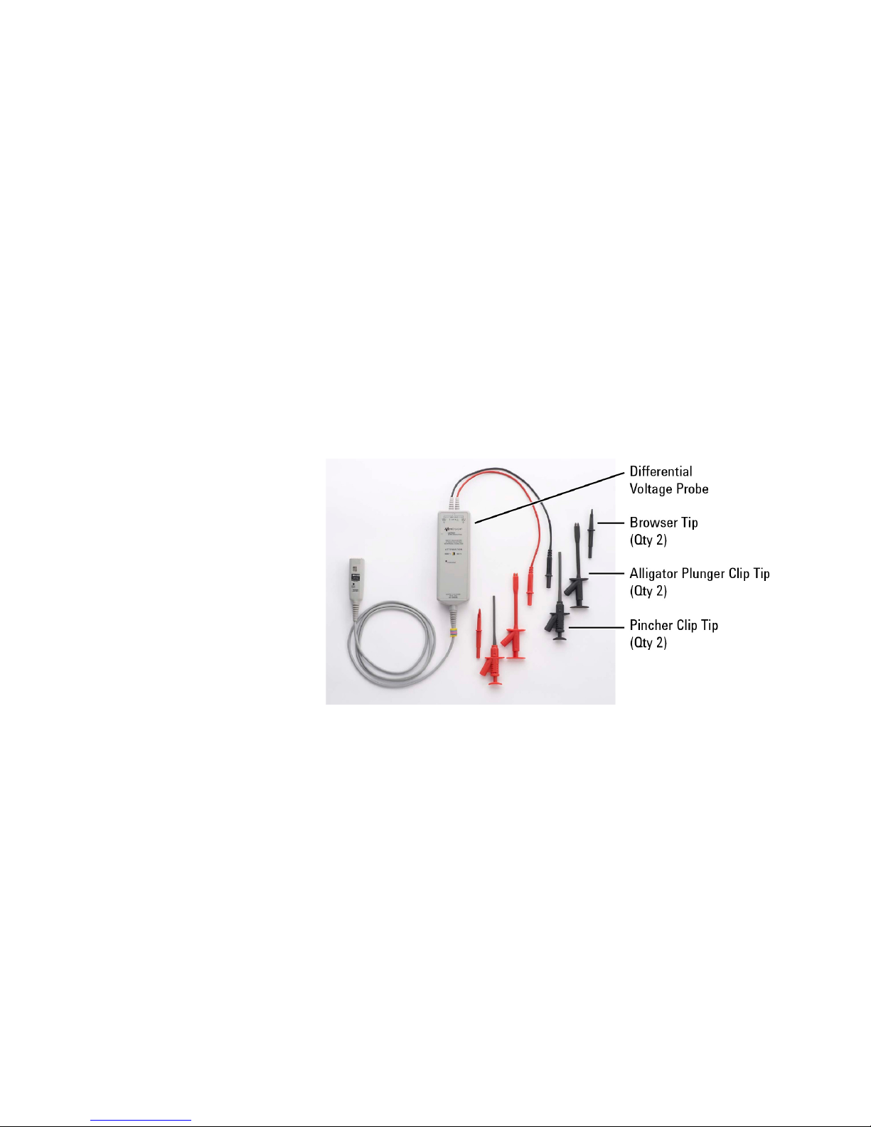
Figure 1 shows the parts supplied with the N2790A Probe. The probe tips
you receive may look slightly different than the ones shown in this picture.
A Probe Tip Accessory Kit (consisting of 2 browser tips, 2 pincher clips, and
2 alligator plunger tips), can be ordered as part number N2790-68700.
Replacement probe tips are not orderable separately. Probe tips are only
for use with the N2790A differential voltage probe.
Figure 1 Probe with Supplied Accessories
6 Keysight N2790A Differential Voltage Probe User Guide
Page 7
Optional Accessories
Introduction
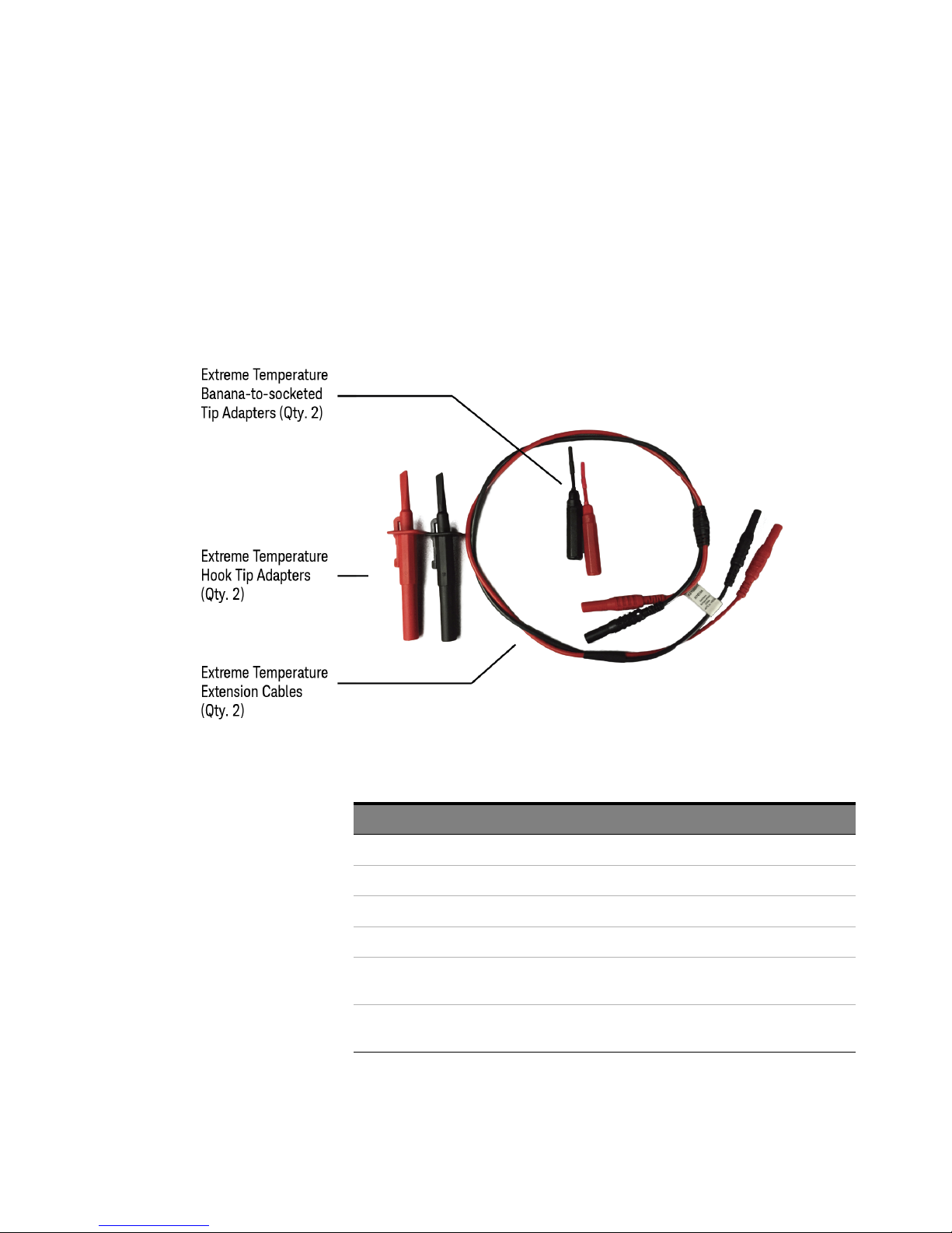
Figure 2 shows the parts you can order separately with the N2790A Probe.
For extreme temperature probing, you can order the N7013/14A Extreme
Temperature Probing kit. This extreme temperature probing kit is
compatible only with the N2790A differential voltage probe. The quantity
for each accessory in the kit is the same as listed in Table 1.
Figure 2 Optional Accessories (Extreme Temperature Probing Kit)
Table 1 Optional Accessories
Accessory Qty
Extreme Temperature Hook Tip Adapters (Black) 1
Extreme Temperature Hook Tip Adapters (Red) 1
Extreme Temperature Differential Extension Cables (Black) 1
Extreme Temperature Differential Extension Cables (Red) 1
Extreme Temperature Banana-to-Socketed Tip Adapters for connecting to
0.025” square pins (Black)
Extreme Temperature Banana-to-Socketed Tip Adapters for connecting to
0.025” square pins (Red)
1
1
Keysight N2790A Differential Voltage Probe User Guide 7
Page 8

Introduction
Cleaning the Probe
Disconnect the probe from all power sources and clean it with a soft cloth
dampened with a mild soap and water solution. Be careful not to get water
in the attenuation switch. Make sure the probe is completely dry before
reconnecting it to a power source.
8 Keysight N2790A Differential Voltage Probe User Guide
Page 9
Safety Information
CAUTION
CAUTION
NOTE
WARNING
!
Safety Information
This apparatus has been designed and tested in accordance with IEC
Publication 1010, Safety Requirements for Measuring Apparatus, and has
been supplied in a safe condition. This is a Safety Class I instrument
(provided with terminal for protective earthing). Before applying power,
verify that the correct safety precautions are taken (see the following
warnings).
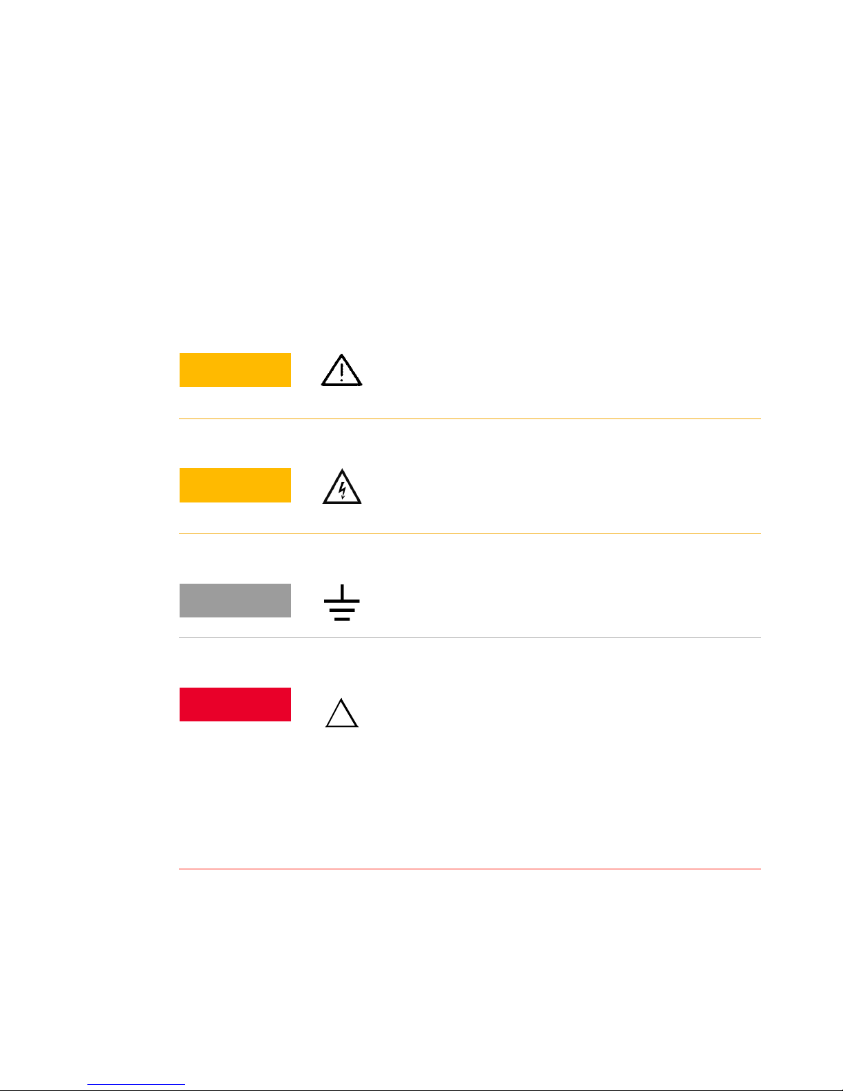
Risk of Danger symbol. Refer to the manual for more
information.
Risk of Electric Shock symbol. Refer to the manual for more
information.
Earth terminal symbol: Used to indicate a circuit common
connected to grounded chassis.
SHOCK HAZARD! These probes are designed for use with
oscilloscopes that have a common terminal at GROUND
POTENTIAL (in accordance with OSHA requirements and the
National Electric Code). Exposed metallic surfaces of the
probe and the oscilloscope MUST BE GROUNDED. Failure to ground the
common terminal during certain applications, such as those requiring
the oscilloscope to be powered from an external battery, might expose
the operator to an electrical shock hazard that could be lethal
(depending on voltage and current conditions.)
Keysight N2790A Differential Voltage Probe User Guide 9
Page 10
Safety Information
WARNING
!
WARNING
!
WARNING
!
WARNING
WARNING
The probe inputs are safety rated to a maximum of 1000 Vrms
CAT II and 600 Vrms CAT III between either input and earth
ground. These maximum ratings apply regardless of the
attenuation setting of the probe. Do not apply voltages greater
than 1000 Vrms CAT II or 600 Vrms CAT III between either input and
ground.
The probe tips that are provided are rated for 1000 Vrms CAT
II and 600 Vrms CAT III usage. Other probe tips may be used if
they have the appropriate ratings and the same style
connectors.
The measurement category of a combination of a PROBE
ASSEMBLY and an accessory is the lower of the measurement
categories of the PROBE ASSEMBLY and of the accessory.
Before turning on the instrument, you must connect the protective earth
terminal of the instrument to the protective conductor of the (mains)
power cord. The mains plug shall only be inserted in a socket outlet
provided with a protective earth contact. You must not negate the
protective action by using an extension cord (power cable) without a
protective conductor (grounding). Grounding one conductor of a
two-conductor outlet is not sufficient protection.
Only fuses with the required rated current, voltage, and specified type
(normal blow, time delay, etc.) should be used. Do not use repaired fuses
or short-circuited fuse-holders. To do so could cause a shock or fire
hazard.
10 Keysight N2790A Differential Voltage Probe User Guide
Page 11
Safety Information
WARNING
WARNING
WARNING
WARNING
WARNING
WARNING
WARNING
If you energize this instrument by an auto transformer (for voltage
reduction or mains isolation), the common terminal must be connected
to the earth terminal of the power source.
Whenever it is likely that the ground protection is impaired, you must
make the instrument inoperative and secure it against any unintended
operation.
Service instructions are for trained service personnel. To avoid
dangerous electric shock, do not perform any service unless qualified to
do so. Do not attempt internal service or adjustment unless another
person, capable of rendering first aid and resuscitation, is present.
Do not install substitute parts or perform any unauthorized modification
to the instrument.
Capacitors inside the instrument may retain a charge even if the
instrument is disconnected from its source of supply.
Do not operate the instrument in the presence of flammable gases or
fumes. Operation of any electrical instrument in such an environment
constitutes a definite safety hazard.
Do not use the instrument in a manner not specified by the manufacturer,
the protection provided by the PROBE ASSEMBLY may be impaired.
Keysight N2790A Differential Voltage Probe User Guide 11
Page 12

Safety Information
WARNING
CAUTION
To clean the instrument. If the instrument requires cleaning: (1) Remove
power from the instrument. (2) Clean the external surfaces of the
instrument with a soft cloth dampened with a mixture of mild detergent
and water. (3) Make sure that the instrument is completely dry before
reconnecting it to a power source.
The probe cable and the extreme temperature extension cables are
sensitive parts and, therefore, you should be careful not to damage them
through excessive bending or pulling. Avoid any mechanical shocks to
this product in order to guarantee accurate performance and protection.
12 Keysight N2790A Differential Voltage Probe User Guide
Page 13
Using the Probe
WARNING
WARNING
NOTE
Using the Probe
This probe has a cable with a built-in wear indicator. When the insulation
of the cable deteriorates, the wear indicator becomes visible. Do not use
the probe, when the contrasting color (Black) is visible through the cable
jacket. Using a product with a worn cable may result in electric shock,
fire, or equipment failure.
Avoid contact of the probe cable with hazardous live voltages. The rated
voltage of the probe tip is higher than the rated voltage of the probe
cable. If the cable contacts hazardous live voltages, it will not provide
adequate protection. Contact of the cable with hazardous live voltages
may result in electric shock, fire, or equipment failure.
The N2790A probe is powered by the auto-probe interface found on
Keysight InfiniiVision and Infiniium Series oscilloscopes.
Using the Supplied Accessories
• Use the supplied sharp browser probe tips for use on small components
and in tight places.
• Use the alligator clips for connecting to larger cables and pincher clips.
Using the Optional Accessories
For extreme temperature probing, connect the N7013/14A extreme
temperature probing kit to this probe.
The N7013/14A extreme temperature probing kit is not supplied with the
probe. You can order this kit separately.
The N7013A extreme temperature probing kit includes:
• One pair of extreme temperature differential extension cables (black
and red)
• One pair of extreme temperature hook tip adapters (black and red)
Keysight N2790A Differential Voltage Probe User Guide 13
Page 14

Using the Probe
CAUTION
• One pair of extreme temperature banana-to-socketed tip adapters for
connecting to 0.025” square pins (black and red)
The N7014A extreme temperature probing kit includes:
• One pair of extreme temperature banana-to-socketed tip adapters for
connecting to 0.025” square pins (black and red)
Only the extension cables and the tip adapters provided with the cables
are rated to extreme temperatures. The differential probe, original
cables, and original accessories should not be exposed to extreme
temperatures. When probing with the extension cables the bandwidth
performance will be reduced, see
Table 2 on page 18.
14 Keysight N2790A Differential Voltage Probe User Guide
Page 15
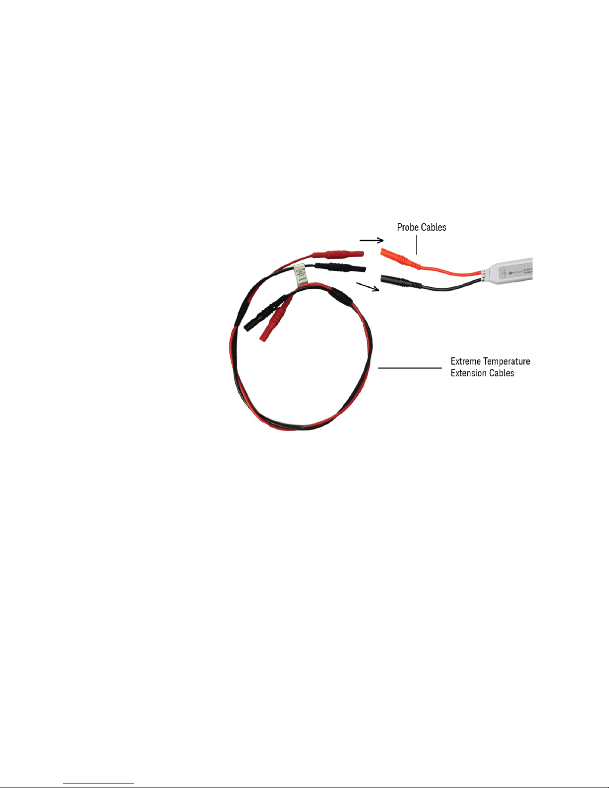
Connecting the Extreme Temperature Probing Kit to the Probe
Perform the following steps to connect the N7013/14A extreme
temperature kit to the N2790A probe:
1 Connect the red and black extreme temperature differential extension
cables to the existing probe cables.
Using the Probe
Figure 3 Connecting the Extreme Temperature Differential Extension Cables
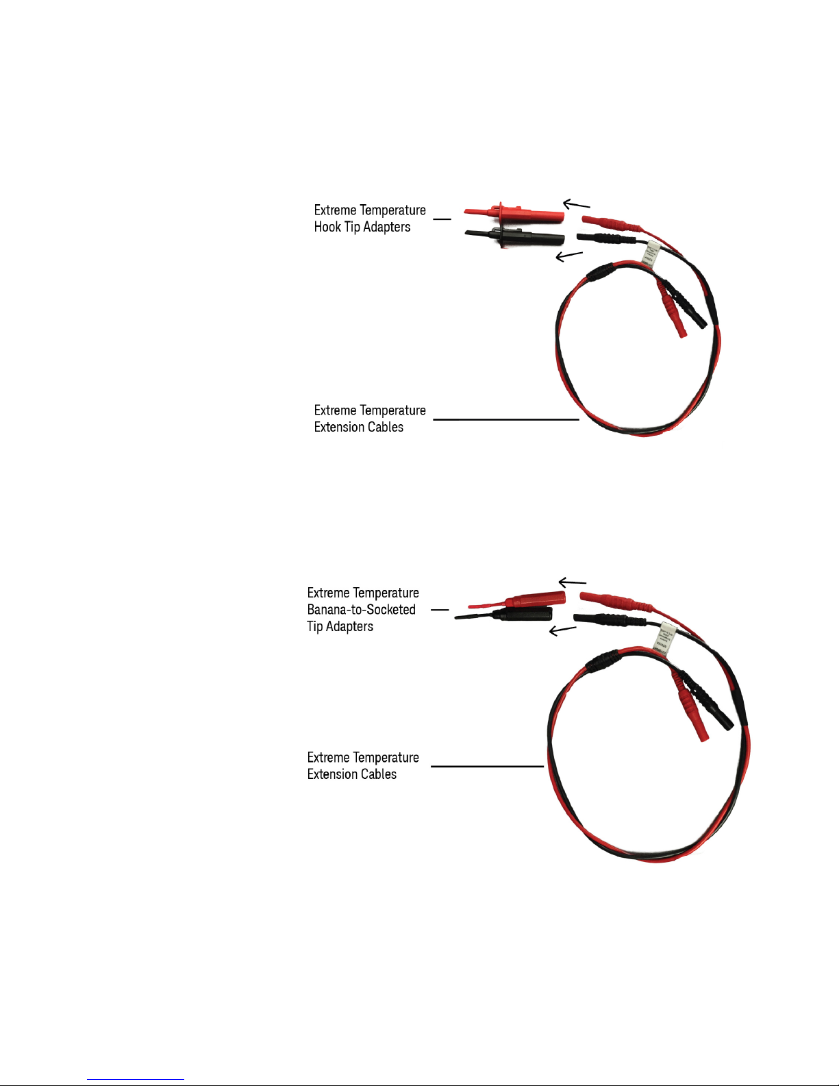
2 Connect the red and black extreme temperature hook tip adapters to
the extreme temperature differential extension cables which are
already connected to the existing probe cables.
Keysight N2790A Differential Voltage Probe User Guide 15
Page 16
Using the Probe
Figure 4 Connecting the Extreme Temperature Hook Tip Adapters
Or,
Connect the red and black extreme temperature banana-to-socketed
tip adapters to the extreme temperature differential extension cables
which are already connected to the existing probe cables.
16 Keysight N2790A Differential Voltage Probe User Guide
Figure 5 Connecting the Extreme Temperature Banana-to-Socketed Tip Adapters
There is an over-range LED on the probe to indicate when you have
exceeded the maximum voltage of the probe.
Page 17
Selecting the Correct Attenuation on the Probe and the Oscilloscope
The probe has two modes of operation, 50:1 and 500:1 attenuation. Use
the 50:1 range on the differential voltage probe for smaller signals, such as
ripple on a high voltage reference lead. To select the desired attenuation
use the switch that is on the probe and set the correct probe attenuation
setting on the oscilloscope. This ensures that accurate voltage readings
can be made directly from the oscilloscope.
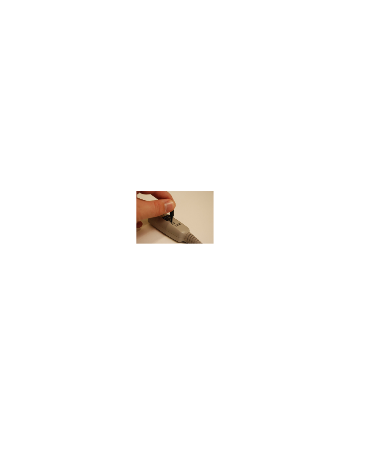
Adjusting the Probe Offset Level
The probe offset level is adjusted using the tool provided with the N2790A
probe. Adjust the offset level by turning the potentiometer adjustment
located on the auto-probe pod.
Using the Probe
Keysight N2790A Differential Voltage Probe User Guide 17
Page 18
Characteristics and Specifications
Characteristics and Specifications
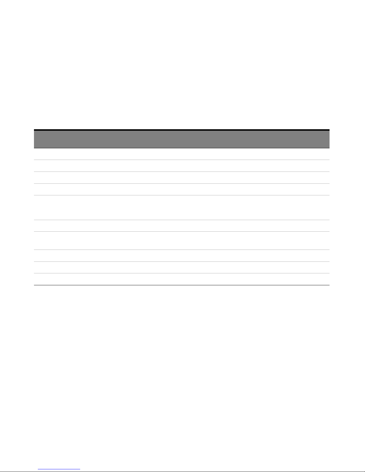
Characteristics and specifications for the N2790A Differential Voltage
Probe are shown below.
Table 2 Electrical Characteristics and Specifications
Description Characteristic/Specification without the N7013/14A
Extreme Temperature Probing Kit
Attenuation Ratios 50:1 and 500:1 (Selectable via switch on probe.) 50:1 and 500:1 (Selectable via switch on probe.)
Bandwidth (–3 dB)
Gain Accuracy* ±4% @ 0 – 20 oC, ±2% @ 20 – 30 oC, ±4% @ 30 – 55 oC ±4% @ 0 – 20 oC, ±2% @ 20 – 30 oC, ±4% @ 30 – 55 oC
DC CMRR –70 dB @ 500VDC –70 dB @ 500VDC
AC CMRR –80 dB @ 50/60 Hz
Input Impedance Between inputs: 8 MΩ, 3.5 pF Between inputs: 8 MΩ, 3.5 pF
Noise Referenced to
Input
Propagation Delay 14.0 ns @ 50:1, 12.8 ns @ 500:1 14.0 ns @ 50:1, 12.8 ns @ 500:1
Switch Positions 500:1, 50:1 500:1, 50:1
Internal Power Autoprobe interface Autoprobe interface
* Denotes warranted specification after 20 minute warm-up
*
100 MHz 70 MHz
–50 dB @ 100 kHz
–50 dB @ 1 MHz
< 300 mVrms @ 500:1
< 50 mVrms @ 50:1
Characteristic/Specification with the N7013/14A Extreme
Temperature Probing Kit
–80 dB @ 50/60 Hz
–50 dB @ 100 kHz
–50 dB @ 1 MHz
< 300 mVrms @ 500:1
< 50 mVrms @ 50:1
18 Keysight N2790A Differential Voltage Probe User Guide
Page 19
Characteristics and Specifications
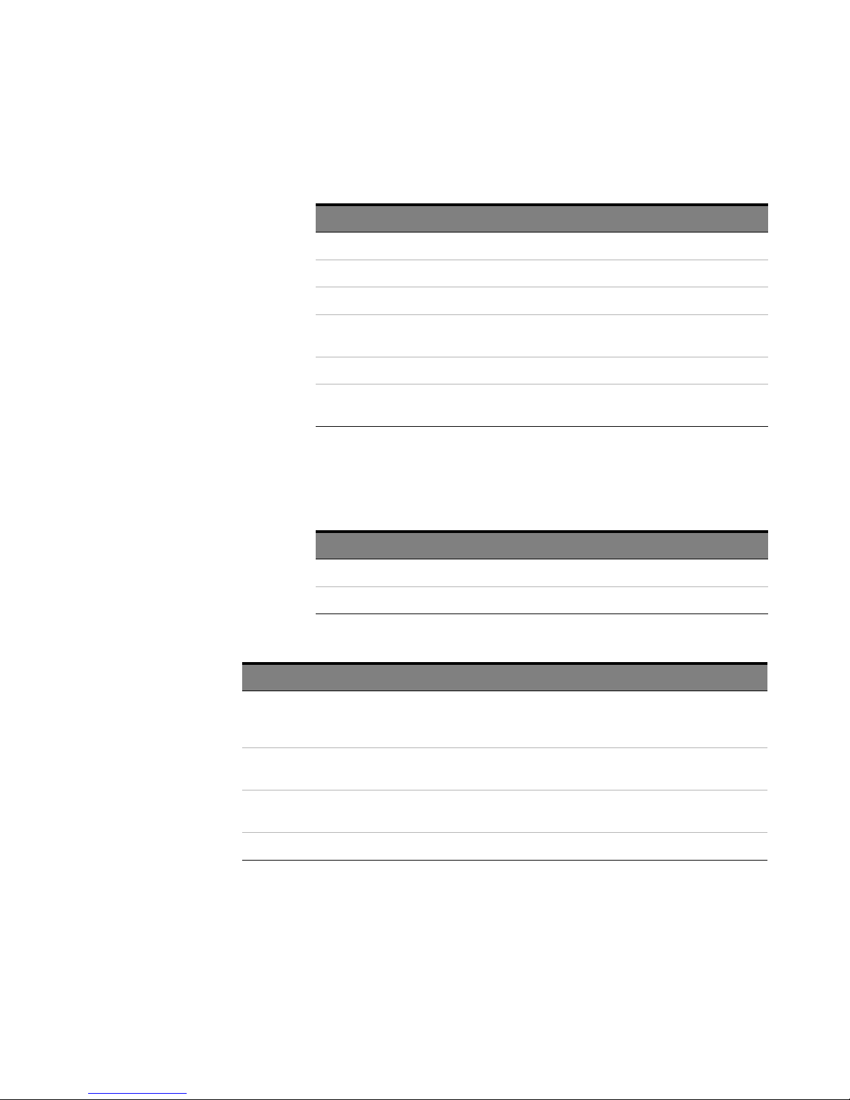
Table 3 Input Characteristics
Description Characteristic
Cable Length 170 cm (66.9 inches)
Length of Extreme Temperature Extension Cables 70 cm (27.5 inches)
Length of Input Leads 40 cm (15.7 inches)
†
*
600V CAT III
1000V CAT II
2 MHz
140V @ 50:1
Maximum Common Mode Operating Voltage (rms or DC + peak AC)
Maximum Common Mode Operating Voltage Derating Frequency
Maximum Differential Mode Operating Voltage (DC + peak AC) 1400V @ 500:1
*Refer to “Safety Information" on page 9 for further details on the input voltage
safety rating.
† Refer to the derating plot in Figure 8 on page 22.
Table 4 Output Characteristics
Description Characteristic
Output Cable Safety designed BNC cable
Maximum Output Voltage Range ±2.8 V into 1 MΩ at 500:1
Table 5 Environmental Specifications
Description Specification
Temperature Operating: –10 °C to +50 °C (Probe without the N7013/14A extreme temperature probing kit)
Operating: –40 °C to +85 °C (Probe with the N7013/14A extreme temperature probing kit)
Non-operating: –51 °C to +71 °C
Altitude Operating: 2,000 m (6,561 feet)
Non-operating: 15,300 m (50,200 feet)
Humidity Operating: 80% room humidity @ 40 °C
Non-operating: 90% room humidity @ 65 °C
Pollution Degree Pollution Degree 2
Keysight N2790A Differential Voltage Probe User Guide 19
Page 20

Characteristics and Specifications
Table 6 Safety Specifications
Description
UL Listed: File No. E326557
Compliant with: UL 61010-031, CSA 22.2 No. 61010-031-07
20 Keysight N2790A Differential Voltage Probe User Guide
Page 21
Characterization Plots
Characterization Plots
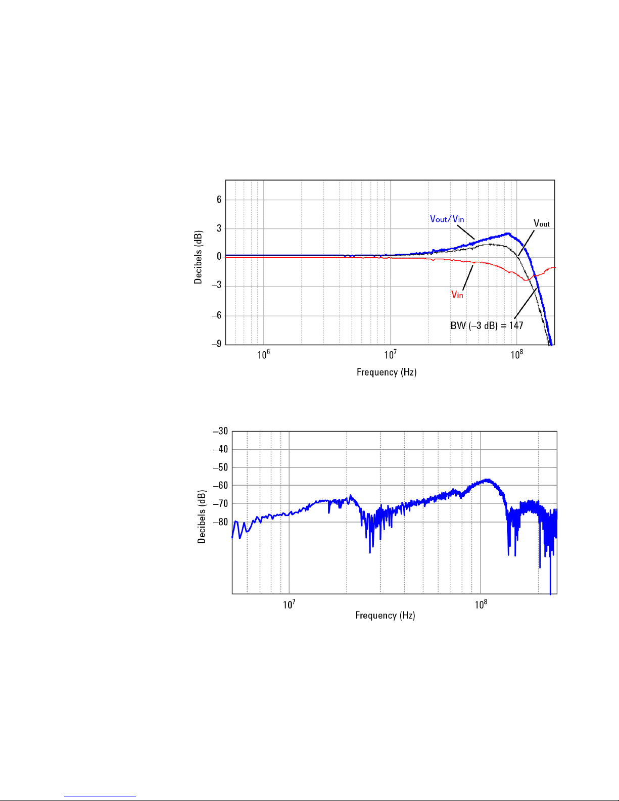
Figure 6 Frequency Response. Graph of dB(Vin), dB(Vout), and dB(Vout/Vin)
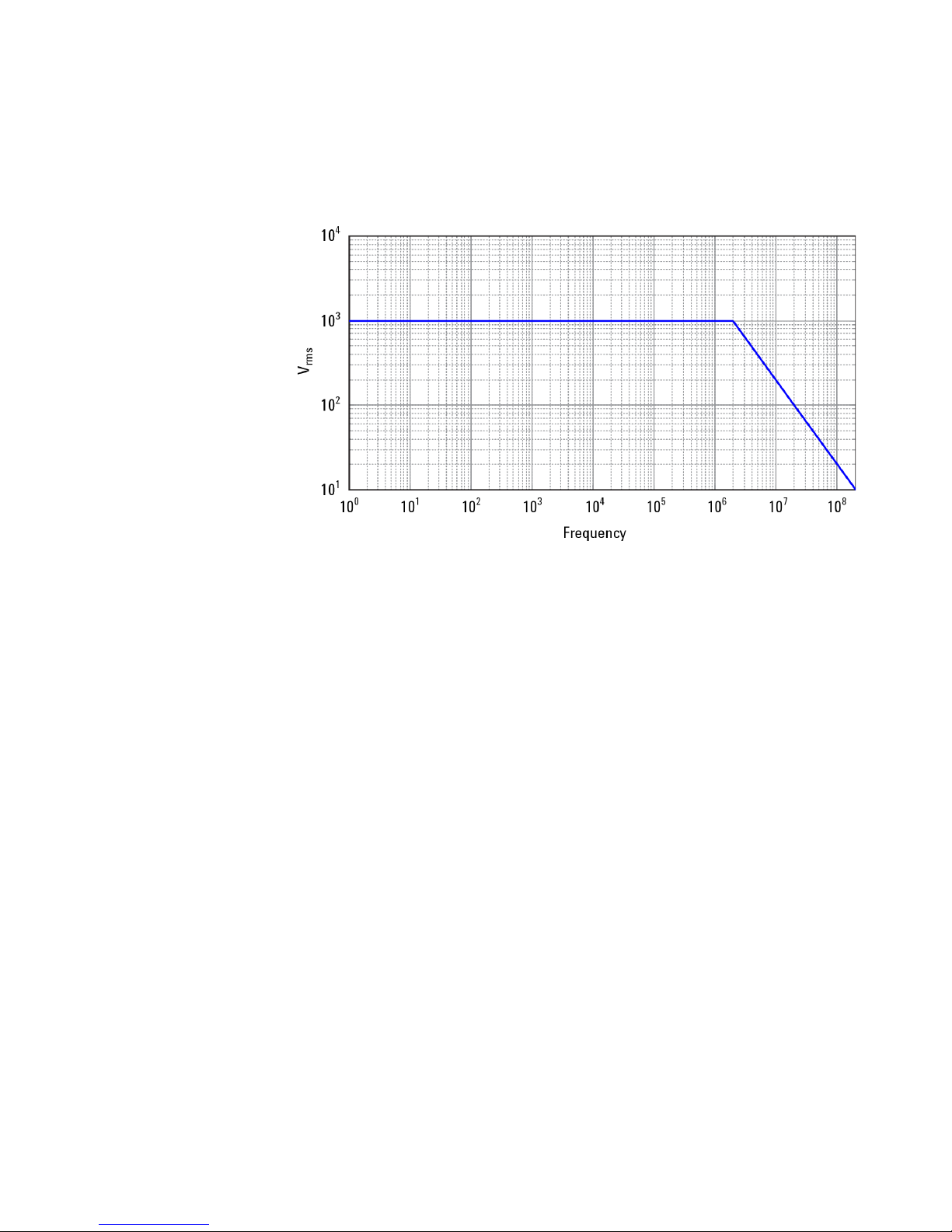
Graph of dB (Vout/Vin) frequency response when inputs are driven in
common (common mode rejection).
Figure 7 Common Mode Rejection Ratio
Keysight N2790A Differential Voltage Probe User Guide 21
Page 22
Characterization Plots
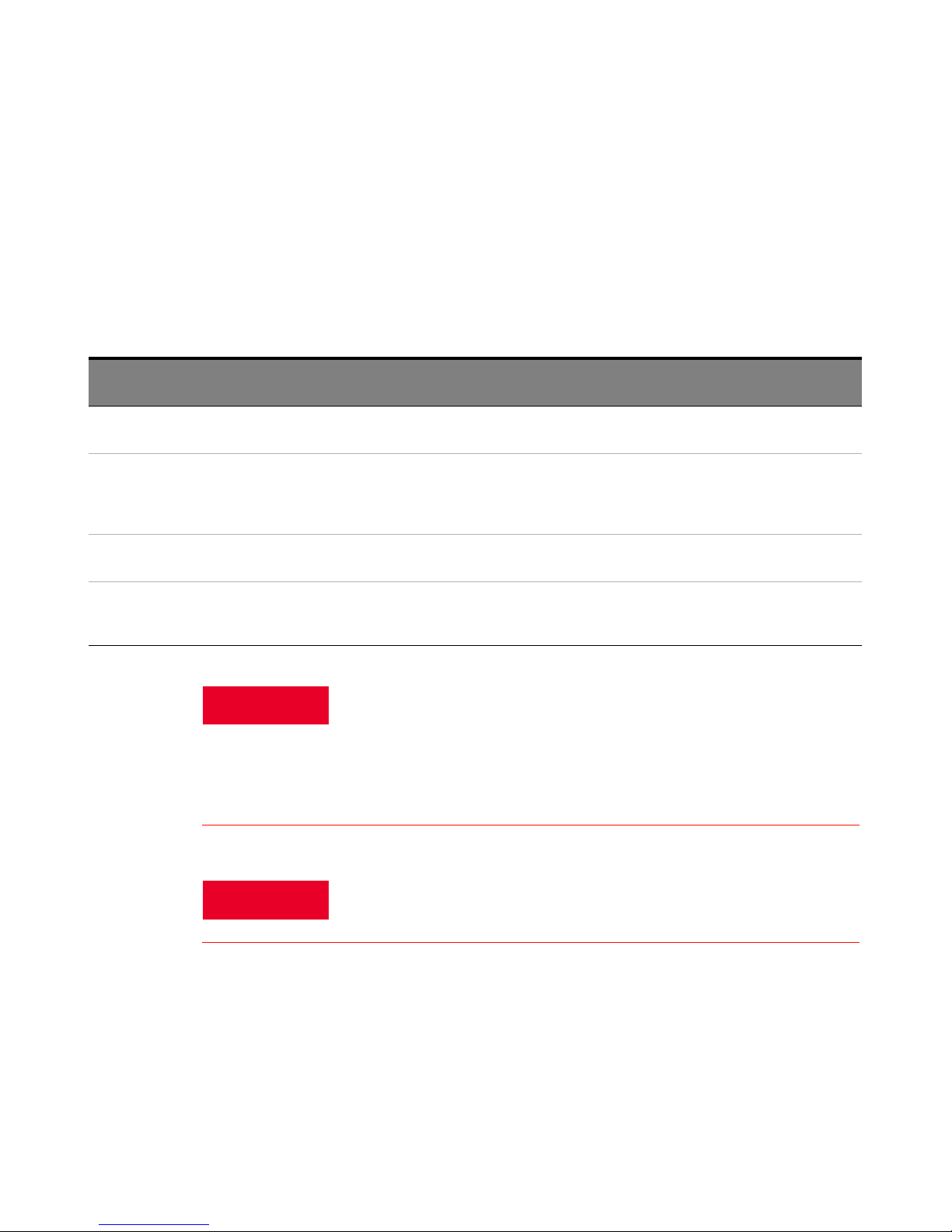
Above 2 MHz, the maximum input operating voltage decreases as the
frequency increases.
Figure 8 Derating Plot
22 Keysight N2790A Differential Voltage Probe User Guide
Page 23
Performance Verification Procedures
WARNING
WARNING
The following procedures can be used to test and verify the DC differential
gain accuracy and bandwidth of the N2790A high voltage differential
probe.
Table 7 Required Test Equipment
Performance Verification Procedures
Description Critical Specifications Recommended Model Part
Number
Digitizing Oscilloscope Bandwidth: >100 MHz
1 MΩ/50Ω selectable input
Signal Generator Precision
DC voltage source
BNC Adapter BNC (f) to Dual Banana (m) Adapter Keysight 1251-2277 Interconnection between probe
50Ω BNC Feed Through
Adapter
Amplitude accuracy: less than or equal to
0.25%
1 MΩ / 50Ω selectable load
Sine wave greater than or equal to 25 MHz
50Ω precision feed through HP 11048C Termination between probe and
Keysight MSO9254A Display probe output
Fluke 9500B or
Fluke 5520A for DC source.
Functions
Signal source for DC gain and
bandwidth
and generator
calibrator for bandwidth
verification
These procedures require the application of high voltage to the inputs of
the N2790A probe. Because the adapter used in this procedure has
exposed metal surfaces, only qualified personnel should perform any
testing with voltage levels exceeding 30V rms. All pertinent safety rules
and guidelines for elevated voltage measurements should be followed
and adhered to.
Keysight N2790A Differential Voltage Probe User Guide 23
Generator produces hazardous voltages. To avoid risk of shock, do not
touch exposed metal parts after the generator output is enabled.
Page 24

Performance Verification Procedures
DC Differential Gain Accuracy
1 Set the volts/division on channel 1 of the oscilloscope to 20 mV/div.
Set the seconds/div to 200
2 Set the volts/division on channel 2 of the oscilloscope to 50 mV/div.
Trigger on channel 2, select 50
3 Set the calibrator 9500B’s channel 2 as the trigger channel (50
Connect the calibrator’s channel 2 active head to channel 2 of the
oscilloscope.
4 Connect the active head channel 1 from the Fluke 9500B to channel 1
of the oscilloscope. Set the calibrator channel 1 to 0.1V peak-to-peak
amplitude and 1 kHz (square wave, 1 M
5 Select the amplitude measurement on the oscilloscope and record the
DC amplitude (approximately 100 mV) of the square wave. This
measurement is only the oscilloscope.
6 Disable the Fluke calibrator output, disconnect the channel 1 active
head from channel 1 of the oscilloscope.
7 Connect the output of the N2790A probe to channel 1 of the
oscilloscope.
8 Attach the BNC adapter to the Fluke channel 1 active head.
9 Attach the differential probe input leads by clipping the alligator clamp
to the BNC adapter banana post.
10 Set the probe to 50:1. Set the Fluke calibrator to 10V and 1 kHz
standard amplitude output (channel 1, square wave, 1 M
11 Enable the output of the calibrator.
12 Record the DC amplitude of the square wave and divide 50 into just the
amplitude of the oscilloscope. Verify that the probe gain accuracy is
±2% + scope gain accuracy.
13 Set the calibrator to 100V output and set the attenuation button on the
probe to 500:1.
14 Record the DC amplitude of the square wave and divide 500 into just
the amplitude of the oscilloscope. Verify that the probe gain accuracy
is ±2% + scope gain accuracy.
15 Disable the calibrator output and leave the setup connected for the
next procedure.
μs and the acquisition mode to average 32.
Ω impedance.
Ω load).
Ω load), enable the output.
Ω load).
24 Keysight N2790A Differential Voltage Probe User Guide
Page 25
Bandwidth
Performance Verification Procedures
1Connect the 50Ω BNC feed through adapter to the calibrator’s active
head channel 1.
2 Attach the BNC (f)-to-banana post adapter to the BNC feed through
adapter.
3 Attach the differential probe input leads by clipping the alligator clamp
to the BNC adapter banana post.
4 Set the probe to 50:1 attenuation.
5 Set the volts/division on channel 1 of the oscilloscope to 1V/div and
seconds/division to 20 ns/div. Set the trace to the center of the
oscilloscope. Input impedance should be set to 1 MΩ. Disable average
mode.
6 Set the calibrator to sine wave, 5V peak-to-peak amplitude. Set the
frequency to 100 MHz, 50Ω load.
7 Record the measured Vpp on the scope and divide it by 50. Write down
the peak-to-peak amplitude measured by the oscilloscope. It should
be greater than or equal to 71 mV + scope error.
8 Disable the generator output and disconnect the probe input.
Performance Verification Test Record
The recommended test interval is 1 year.
Table 8 N2790A Performance Test Record
Certification Details
Serial Number: Tested By:
Certification Date: Recommended Date of Next Certification:
Certification Temperature:
Tes t Probe Setting Test Limits Test Results
Gain 50:1 196 mV to 204 mV
Gain 500:1 196 mV to 204 mV
Bandwidth 50:1 ≥ 71 mV
Keysight N2790A Differential Voltage Probe User Guide 25
Page 26

Service
Service
For repair, calibration, and to ensure the N2790A performs to its
warranted specifications, send the probe to an Keysight Service Center for
calibration testing procedures. The probe should be tested once a year or
as required by other standards. If repair is needed and the N2790A is
under warranty, normal warranty services will apply. If the N2790A is not
under warranty, repair costs will be applied.
To return the probe to Keysight Technologies for service, call
(877) 477-7278 for further details and the location of your nearest
Keysight Technologies Service Office.
1 Write the following information on a tag and attach it to the probe.
• Name and address of the owner
• Probe model number
• Description of service required or failure indication
2 Retain all accessories.
3 Return the probe in its case or pack the probe in foam or other
shock-absorbing material and place it in a strong shipping container.
You can use the original shipping materials or order materials from an
Keysight Technologies Sales Office. If neither are available, place 3 to 4
inches of shock-absorbing material around the instrument and place it
in a box that does not allow movement during shipping.
4 Seal the shipment container securely.
5 Mark the shipping container as FRAGILE. In all correspondence, refer
to the instrument by model number and full serial number.
26 Keysight N2790A Differential Voltage Probe User Guide
Page 27

Keysight N2790A Differential Voltage Probe User Guide 27
Page 28

This information is subject to
change without notice.
© Keysight Technologies 2018
N2790-97005
Edition 4, September 2018
www.keysight.com
 Loading...