

Page 1

Keysight M9614A/M9615A
PXIe 5-Channel
Precision Source/Measure Unit
Startup Guide
Page 2

Notices
Copyright Notice
© Keysight Technologies 2020
No part of this manual may be reproduced in
any form or by any means (including electronic storage and retrieval or translation into
a foreign language) without prior agreement
and written consent from Keysight Technologies as governed by United States and international copyright laws.
Manual Part Number
M9615-90000
Edition
Edition 1, May 2020
Edition 2, August 2020
Edition 3, October 2020
Published by:
Keysight Technologies Japan K.K.
9-1, Takakura-cho, Hachioji-shi, Tokyo
192-8550 Japan
Regulatory Compliance
This product has been designed and tested in
accordance with accepted industry standards,
and has been supplied in a safe condition. To
review the Declaration of Conformity, go to
www.keysight.com/go/conformity.
Warranty
THE MATERIAL CONTAINED IN THIS DOCUMEN T IS PROVIDED “AS I S,” A ND IS SUBJ ECT
TO BEING CHANGED, WITHOUT NOTICE, IN
FUTURE EDITIONS. FURTHER, TO THE MAXIMUM EXTENT PERMITTED BY APPLICABLE
LAW, KEYSIGHT DISCLAIMS ALL WARRANTIES, EITHER EXPRESS OR IMPLIED, WITH
REGARD TO THIS MANUAL AND ANY INFORMATION CONTAINED HEREIN, INCLUDING
BUT NOT LIMITED TO THE IMPLIED WARRANTIES OF MERCHANTABILITY AND FITNESS FOR A PARTICULAR PURPOSE.
KEYSIGHT SHALL NOT BE LIABLE FOR
ERRORS OR FOR INCIDENTAL OR CONSE-
QUENTIAL DAMAGES IN CONNECTION WITH
THE FURNISHING, USE, OR PERFORMANCE
OF THIS DOCUMENT OR OF ANY INFORMATION CONTAINED HEREIN. SHOULD KEYSIGHT AND THE USER HAVE A SEPARATE
WRITTEN AGREEMENT WITH WARRANTY
TERMS COVERING THE MATERIAL IN THIS
DOCUMENT THAT CONFLICT WITH THESE
TERMS, THE WARRANTY TERMS IN THE SEPARATE AGREEMENT SHALL CONTROL.
KEYSIGHT TECHNOLOGIES DOES NOT WARRANT THIRD-PARTY SYSTEM LEVEL (COMBINATION OF CHASSIS, CONTROLLERS,
MODULES, ETC.) PERFORMANCE, SAFETY,
OR REGULATORY COMPLIANCE, UNLESS
SPECIFICALLY STATED.
Technology Licenses
The hardware and/or software described in
this document are furnished under a license
and may be used or copied only in accordance
with the terms of such license.
U.S. Government Rights
The Software is “commercial computer software,” as defined by Federal Acquisition Regulation (“FAR”) 2.101. Pursuant to FAR 12.212
and 27.405-3 and Department of Defense FAR
Supplement (“DFARS”) 227.7202, the U.S.
government acquires commercial computer
software under the same terms by which the
software is customarily provided to the public.
Accordingly, Keysight provides the Software
to U.S. government customers under its standard commercial license, which is embodied
in its End User License Agreement (EULA), a
copy of which can be found at http://
www.keysight.com/find/sweula. The license
set forth in the EULA represents the exclusive
authority by which the U.S. government may
use, modify, distribute, or disclose the Software. The EULA and the license set forth
therein, does not require or permit, among
other things, that Keysight: (1) Furnish technical information related to commercial computer software or commercial computer
software documentation that is not customar-
ily provided to the public; or (2) Relinquish to,
or otherwise provide, the government rights
in excess of these rights customarily provided
to the public to use, modify, reproduce,
release, perform, display, or disclose commercial computer software or commercial
computer software documentation. No additional government requirements beyond those
set forth in the EULA shall apply, except to the
extent that those terms, rights, or licenses are
explicitly required from all providers of commercial computer software pursuant to the
FAR and the DFARS and are set forth specifically in writing elsewhere in the EULA. Keysight shall be under no obligation to update,
revise or otherwise modify the Software. With
respect to any technical data as defined by
FAR 2.101, pursuant to FAR 12.211 and
27.404.2 and DFARS 227.7102, the U.S. government acquires no greater than Limited
Rights as defined in FAR 27.401 or DFAR
227.7103-5 (c), as applicable in any technical
data.
Safety Summary
The following general safety precautions must
be observed during all phases of operation,
service, and repair of this product. Failure to
comply with these precautions or with specific
warnings elsewhere in this manual may impair
the protections provided by the product. In
addition, it violates safety standards of design,
manufacture, and intended use of the product.
Keysight Technologies assumes no liability for
customer’s failure to comply with these
requirements.
- Do not use this product in any manner not
specified by the manufacturer. The protective
features of this product may be impaired if it is
used in a manner not specified in the operation instructions.
- This product is INDOOR USE product.
- This product complies with POLLUTION
DEGREE 2 defined in IEC 61010-1.
Page 3

- If an instrument is marked CAT I (IEC Mea-
WARNING
WARNING
>
^
surement Category I), or it is not marked with
a measurement category, its measurement
terminals must not be connected to line-voltage mains.
- System installation, safety and performance
are the responsibility of the assembler of the
system.
The persons who plan, supervise, consign, and
implement the installation, start-up, maintenance, and delivery of this product are
required to carefully read documents related
to the equipment and take and implement
safety measures to prevent accidents. Also,
safety and performance of the system in which
the equipment is installed are the responsibility of the assembler responsible for the system
construction.
Equipment built in the system may be heavy.
So there is the possibility of physical disability
in the person by moving the equipment to a
high place or moving it from a high place. To
prevent accidents, take appropriate safety
work means.
DANGEROUS PROCEDURE WARNINGS
Warnings, such as above WARNING, shall be
complied. Procedures throughout in this manual prevent you from potentially hazard. Their
instructions contained in the warnings must
be followed.
BEFORE APPLYING POWER
Verify that all safety precautions are taken.
Make all connections to the instrument before
applying power. Note the instrument's external markings described under “Safety Symbols”.
GROUND THE INSTRUMENT
This is Safety Class I instrument. To minimize
shock hazard, the instrument chassis and cabinet must be connected to an electrical
ground. The power terminal and the power
cable must meet International Electrotechnical Commission (IEC) safety standards.
DO NOT OPERATE IN AN EXPLOSIVE
ATM OSP HER E
Do not operate the instrument in the presence
of flammable gases or fumes. Operation of any
electrical instrument in such an environment
constitutes a definite safety hazard.
DO NOT REMOVE COVERS
No operator serviceable parts inside. Refer
servicing to qualified personnel. To prevent
electrical shock do not remove covers.
IN CASE OF DAMAGE
Instruments that appear damaged or defective
should be made inoperative and secured
against unintended operation until they can be
repaired by qualified service personnel.
Return the instrument to a Keysight Technologies sales or service office for services and
repair to ensure that safety features are maintained.
USE ONLY THE SPECIFIC ACCESSORIES
Specific accessories satisfy the requirements
for specific characteristics for using the
instrument. Use the specific accessories,
cables, adapters, and so on for safety reasons.
Safety Symbols
The general definitions of safety symbols used
on equipment or in manuals are listed below.
Direct current.
Alternating current.
Earth ground terminal.
Protective conductor terminal. For
protection against electrical shock
in case of a fault. Used with field
wiring terminals to indicate the terminal which must be connected to
ground before operating equipment.
Frame or chassis terminal. A connection to the frame (chassis) of the
equipment which normally includes
all exposed metal structures.
Grounded terminal which indicates
the earth potential.
On supply.
Off supply.
Standby supply. The equipment will
be marked with this symbol is not
completely disconnected from AC
mains when power switch is in the
standby position.
In position of a bi-stable push
switch.
Out position of a bi-stable push
switch.
Hazardous voltage and potential for
electrical shock. Do not touch terminals that have this symbol when
the equipment is on.
Hot surface. Avoid contact. Surfaces are hot and may cause personal injury if touched.
Low temperature or freezing conditions. Avoid contact. Surfaces are
cold and may cause personal injury
if touched.
Heavy object. Lifting can cause
back injury. Use mechanical lifting
device to move.
Page 4

Caution, refer to accompanying
CAUTION
WARNING
CAT I
یࡈ߇ΰח
넩韥韥鱉꽺ꓩ끞쀍陲꾅ꩡ끞뼕ꑞ놶냱ꈑ
놶뼞ꫦ뵾閵ꌱꗐ냵韥韥ꈑ閵뇊끞쀍陲꾅
ꩡ끞뼍鱉陲끥놹볁閹ꫢ넍끥ꇙ閵넽걪鱽鲙
놶끞뼑鲙
ꩡ끞녅껽驩ꓭ냵ಯ꽺ꓩ끞ꗞꭖ뭪겕韥녅녡ರ꾅ꎁ
(*)
documentation. The equipment
will be marked with this symbol
when it is necessary for the user
to refer to the instruction manual.
Read operator's manual. To indicate that the operator's manual or
card should be read before continuing the operation.
Affixed to product containing
static sensitive devices--use antistatic handling procedures to
prevent electrostatic discharge
damage to component.
IEC Measurement Category I
The CE mark shows that the
product complies with all applicable European Directives.
The CSA mark is a registered
trademark of the Canadian Standards Association.
The RCM mark is a registered
trademark of the Australian Communications Authority. This signifies compliance with the
Australian EMC Framework Regulations under the terms of the
Radio communications Act.
This ISM device complies with Canadian
ICES-001.
Cet appareil ISM est conforme à la norme
NMB-001 du Canada.
This is the symbol for an Industrial, Scientific
and Medical, Group 1 Class A product. (CISPR
11)
Korea’s safety and EMC mark
China RoHS - Environmentally
Green Product Label
China RoHS - Product with Toxic
Substance 40 yr EPUP
The Chinese mark for paperbased packaging materials;
Paperboard and Corrugated
Fiberboard
Plastic Material Coding Identification
A CAUTION denotes a hazard. It calls attention
to an operating procedure or practice, that, if
not correctly performed or adhered to could
result in damage to the product or loss of
important data. Do not proceed beyond a
CAUTION notice until the indicated conditions
are fully understood and met.
A WARNING denotes a hazard. It calls attention to an operating procedure or practice,
that, if not correctly performed or adhered to,
could result in personal injury or death. Do not
proceed beyond a WARNING notice until the
indicated conditions are fully understood and
met.
Waste Electrical and
Electronic Equipment
(WEEE) Directive 2002/
96/EC
This product complies with the WEEE Directive (2002/96/EC) marking requirements. The
affixed label ind icates that you must not discard this electrical/ electronic product in
domestic household waste.
Product Category: With reference to the
equipment types in the WEEE directive Annex
1, this product is classified as a “Monitoring
and Control instrumentation” product.
Do not dispose in domestic household waste.
To return unwanted products, contact your
local Keysight office or visit the following
website for more information.
http://about.keysight.com/en/companyinfo/
environment/
South Korean EMC Declaration
Information to the user:
This equipment has been conformity assessed
for use in business environments. In a residential environment this equipment may
cause radio interference.
(*) This EMC statement applies to the equipment only for use in business environment.
Cleaning Precautions
To prevent electrical shock, disconnect the
Keysight Technologies instrument from mains
before cleaning. Use a dry cloth or one slightly
dampened with water to clean the external
case parts. Do not attempt to clean internally.
To clean the connectors, use alcohol in a wellventilated area. Allow all residual alcohol
moisture to evaporate, and the fumes to dissipate prior to energizing the instrument.
Page 5

Keysight M9614A/M9615A Precision Source/Measure Unit
Startup Guide
Contents
Introduction 7
Related Documentation 7
Step 1: Unpack and Inspect the Module 8
Electrostatic Discharge (ESD) Precautions 8
Before Unpacking 9
Inspect for Damage 9
Return the Module for Service 10
Step 2: Verify Shipment Contents 11
Step 3: Install the Software 12
Requirements 12
Installation Process 12
Step 4: Install the Module 13
Step 5: Verify Operation of the Module 15
To Check Communication 15
To Update the Firmware 16
To Perform Self Test 17
Front Panel Features 18
LED Indicators 19
Measurement Terminals 19
Trigger and Interlock Terminals 23
Connecting a DUT 24
2-Wire Connection or 4-Wire Connection 25
Page 6

F
loating 27
Guarding 28
Installing Interlock Circuit 29
Maintenance 32
Cleaning 32
Self Test 33
Self Calibration 34
Calibration 34
Function Overview 35
Limit (Compliance) 35
Operation Mode 35
Output Filter 36
Pulse Output 36
Sweep Output 36
Ranging Mode 37
Seamless Current Measurement Ranging 37
Trigger System 38
Measurement Time 39
Automatic Output On/Off 39
Output Off Mode 39
Interlock 40
Over Temperature Protection 41
Page 7

Introduction
Related Documentation
Introduction
The Keysight M9614A/M9615A 5-Channel Precision Source/Measure Unit (SMU)
delivers high channel density per a single slot module, wide output range, and
easy installation and configuration via the Keysight Connection Expert and a soft
front panel (SFP).
• M9614A PXIe 5-Channel SMU, 500 kSa/s, 100 pA, 30 V, 500 mA
• M9615A PXIe 5-Channel Precision SMU, 500 kSa/s, 10 pA, 30 V, 500 mA
Keysight also supplies software drivers that allow you to support the modules in
many popular PXI chassis and programming environments. You can control the
M9614A/M9615A using IVI drivers. LabVIEW driver is also available.
This Startup Guide, and the documentation listed below, can be found on the
Keysight web site. Visit www.keysight.com/find/m9614a or
www.keysight.com/find/m9615a to get the latest documents, specifications, and
software.
• Soft Front Panel User’s Guide
• IVI.NET Driver Reference
• IVI-C Driver Reference
• LabVIEW Driver Help
• Data sheet
• Configuration guide
Keysight M9614A/M9615A Startup Guide, Edition 3 7
Page 8
Step 1: Unpack and Inspect the Module
Step 1: Unpack and Inspect the Module
Keysight’s PXIe chassis and instrument modules are shipped in materials which
prevent static electricity damage. The modules should only be removed from the
packaging in an anti-static area ensuring that correct anti-static precautions are
taken. Store all modules in anti-static envelopes when not in use.
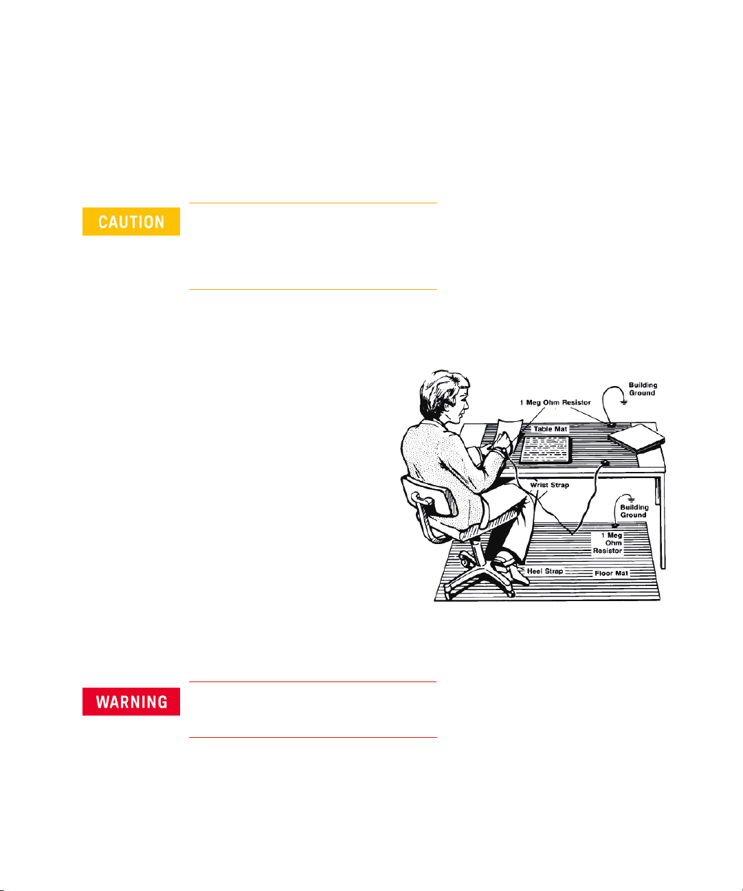
Electrostatic Discharge (ESD) Precautions
Electrostatic discharge (ESD) can
damage or destroy electronic
components. Use a static-safe
work station to perform all work
on electronic assemblies. This
figure shows a static-safe work
station using two types of ESD
protection.
• Conductive table mat and
wrist strap combination
• Conductive floor mat and heel
strap combination
Both types, when used together,
provide a significant level of ESD
protection. Of the two, only the table mat and wrist strap combination provides
adequate ESD protection when used alone. To ensure user safety, the static-safe
accessories must provide at least 1 M of isolation from ground.
DO NOT use these techniques for a static-safe work station when working on
circuitry with a voltage potential greater than 500 V.
8 Keysight M9614A/M9615A Startup Guide, Edition 3
Page 9

Before Unpacking
Keysight M9614A/M9615A module is designed to meet IEC/EN61010-1 and must
only be installed in the PXIe chassis which is certified by a Nationally Recognized
Testing Laboratory. The PXIe chassis must already be installed on a static-safe
workbench so that you can install the module soon after unpacking.
Refer to the PXIe chassis manual for chassis installation and details.
Inspect for Damage
After unpacking a module, carefully inspect it for any shipping damage. Report
any damage to the shipping agent immediately, as such damage is not covered by
the warranty (see warranty information at the beginning of this document).
To avoid damage when handling a module, do not touch any exposed
components or connector pins.
Visit www.keysight.com/find/tips for information on preventing damage to your
Keysight equipment.
Step 1: Unpack and Inspect the Module
Keysight M9614A/M9615A Startup Guide, Edition 3 9
Page 10

Step 1: Unpack and Inspect the Module
Return the Module for Service
Should it become necessary to return a module for repair or service, follow the
steps below.
1. Review the warranty information shipped with your product.
2. Contact Keysight to obtain a Return Material Authorization (RMA) and return
address. For assistance in finding Keysight contact information, visit
www.keysight.com/find/assist.
3. Write the following information on a tag and attach it to the malfunctioning
equipment.
• Name and address of owner. A Post Office box is not acceptable as a return
address.
• Product model number (for example, M9615A)
• Product serial number (for example, MYXXXXXXXX). The serial number
label is located on the side of the module.
• Description of failure or service required
4. Carefully pack the module in its original ESD bag and packing carton. If the
original carton is not available, use bubble wrap or packing peanuts and place
the instrument in a sealed container and mark the container “FRAGILE.”
5. On the shipping label, write ATTENTION REPAIR DEPARTMENT and the RMA
number.
If any correspondence is required, refer to the product by serial number and model
number.
10 Keysight M9614A/M9615A Startup Guide, Edition 3
Page 11

Step 2: Verify Shipment Contents
The following items are included in this shipment.
Table 1-1 Shipment Contents
Model number Description Quantity
Step 2: Verify Shipment Contents
M9614A
or M9615A
NA Quick Startup Poster 1
NA Certification of calibration (without test data) 1
NA Short bar 1
NA Connector-terminal block 2.5 mm 5-terminal 1
Consumable supplies of the M9614A/M9615A are shown in below.
Table 1-2 Consumable Supplies
Part number Description Quantity
M9601-87001 Short bar 5
M9615-87001 Connector-terminal block 2.5 mm 5-terminal 5
PXIe 5-Channel Precision Source/Measure Unit 1
Keysight M9614A/M9615A Startup Guide, Edition 3 11
Page 12

Step 3: Install the Software
Step 3: Install the Software
Install the software prior to installing the PXIe modules in the chassis so that
Keysight IO Libraries Connection Expert finds them.
Requirements
The followings are required for installing the M9614A/M9615A software.
• Controller (desktop PC, laptop PC, rackmount PC, or PXIe embedded
computer) installed with Keysight IO Libraries Suite
• Keysight PXIe chassis which has already been set up
For setting up the controller and the PXIe chassis, refer to the PXIe chassis
documentation.
Minimum 1.5 GB free space is required on the controller for installing the
M9614A/M9615A software.
Installation Process
Visit www.keysight.com/find/m9614a or www.keysight.com/find/m9615a to get
the latest version of the M9614A/M9615A software.
1. Copy the M9614A/M9615A software installer into the controller.
2. Launch the M9614A/M9615A software installer.
3. Follow the installer prompts to install the M9614A/9615A software.
4. Reboot the controller when prompted by the software installer.
If a firmware update is available, you can perform the firmware update by using
the M960x PXIe Source Measure Unit Soft Front Panel (the M960x SFP) after the
module installation. See “To Update the Firmware” on page 16.
12 Keysight M9614A/M9615A Startup Guide, Edition 3
Page 13
Step 4: Install the Module
Current capacity of the PXIe chassis may restrict the module configuration. For
more information, refer to the M9614A/M9615A data sheet and the PXIe chassis
documentation.
The M9614A/M9615A module must be installed in the PXIe chassis certified by a
Nationally Recognized Testing Laboratory.
PXIe hardware does not support “hot-swap” (changing modules while power is
applied to the chassis) capabilities. Before installing or removing a module
to/from the chassis, power down the chassis to prevent damage to the module.
Place the chassis on a static-safe work station (see “Electrostatic Discharge
(ESD) Precautions” on page 8). And position it so that there is ample space
between the chassis fan intake and exhaust vents. Blockage by walls or
obstructions affects the air flow needed for cooling. Use slot blockers and filler
panels in empty slots to ensure proper operating temperatures.
Step 4: Install the Module
For more information about precautions and cooling, refer to the PXIe chassis
documentation.
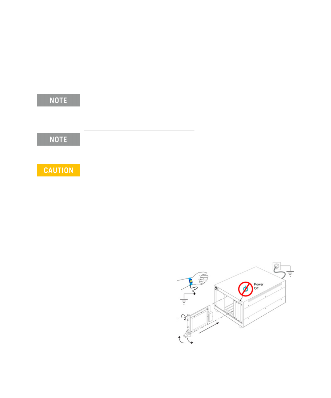
Generic module installation is
shown below. It may not
reflect your module’s actual
size and chassis placement.
Install the leftmost module
first and continue installing
modules from left to right
according to the image
below.
Keysight M9614A/M9615A Startup Guide, Edition 3 13
Page 14

Step 4: Install the Module
Before the module installation, make sure that the controller is turned off.
Procedure 1. Make sure that the power cord is plugged into a grounded outlet to establish
earth ground and to prevent ESD.
2. Make sure that the chassis power switch is off.
3. If the chassis has multiple fan speed settings, ensure that the fans are set to
automatic. Do not set the fan speed to low or turn them off.
4. Remove the filler panel that covers the slot in which you want to install the
module.
5. Remove thread protectors from the top and bottom mounting screws of the
module.
6. Hold the module by the injector/ejector handle, and slide it into the slot.
• Install the module into the slot of the chassis by placing the module card
edges into the front module guides (top and bottom).
• Slide the module to the rear of the chassis and assure that the injector/
ejector handle is pushed down in the unlatched (downward) position.
• Slide the module completely into the chassis. When you begin to feel
resistance, push up on the injector/ejector handle to fully seat the module
into the chassis.
7. Latch the module by pulling up on the injector/ejector handle and secure the
front panel to the chassis using the module front-panel mounting screws.
8. Tighten the screws on the module front panel. Performance may suffer if the
screws are not securely tightened.
9. Install all chassis covers, filler panels, and air scoops after installing the
module. Also see CAUTION below.
For more information on the module installation, refer to the PXIe chassis
documentation.
Ensure that filler panels are installed in all empty slots. Missing filler panels will
impact cooling of the chassis and may cause RFI (radio frequency interference)
with other devices.
14 Keysight M9614A/M9615A Startup Guide, Edition 3
Page 15

Step 5: Verify Operation of the Module
If you are using a remote controller (rackmount, desktop, or laptop PC), and you
have installed the interface cable, you must power up the chassis before you
power up the controller. When you power down your system, shut down the
controller before you power down the chassis.
To Check Communication
Perform the following procedure to check the communication between the
module and the controller.
1. Make sure that the chassis and the controller are turned off.
2. If you are using a remote controller, connect a PXIe cable between the chassis
and the controller.
3. Power up the chassis. Verify that the chassis fans are operating and free of
obstructions that may restrict airflow.
Step 5: Verify Operation of the Module
4. Power up the controller.
5. Check that the controller automatically recognizes the module in the device
manager; e.g. via Start menu > Windows System Tools > Control Panel >
Device Manager. The module should be visible in the device tree.
The controller might request a reboot. Reboot the controller, if requested.
6. Check if the module is also visible in the Keysight Connection Expert; e.g. via
Start menu > Keysight Connection Expert.
If something went wrong and the module is not shown in the PXIe section, it
may be necessary to reboot the controller once more.
Keysight M9614A/M9615A Startup Guide, Edition 3 15
Page 16

Step 5: Verify Operation of the Module
To Update the Firmware
If a firmware update is available, perform the following procedure to update the
firmware of the M9614A/M9615A modules.
1. Click Start menu > Keysight M960x Source Measure Unit > M960x SFP. The
Connect to Instrument dialog box will open.
2. In the list on the window, highlight the M9614A/M9615A modules to connect,
and click Connect to launch the Keysight M960x PXIe Source Measure Unit
Soft Front Panel (the M960x SFP).
3. Confirm that the Access indicator on the M9614A/M9615A front panel turns
green. Refer to Figure 1-1 and Table 1-3 for LED status.
4. Select Firmware Update... from the Utilities menu. The Firmware Update
dialog box will open.
5. Select the latest version of the firmware, if it is available.
If the select menu displays “No change”, there are no firmware updates.
6. Click Update at the bottom of the Firmware Update dialog box to start the
firmware update.
When the firmware is updated successfully, the message appears in the
Firmware Update dialog box.
7. Close the M960x SFP.
8. Restart your system; Power down the controller, then the chassis, and power
up the chassis, then the controller.
16 Keysight M9614A/M9615A Startup Guide, Edition 3
Page 17

To Perform Self Test
You can perform the self test by using the M960x PXIe Source Measure Unit Soft
Front Panel (the M960x SFP).
Before performing the self test, turn the instrument output off and disconnect
cables from the measurement terminals.
1. Click Start menu > Keysight M960x Source Measure Unit > M960x SFP. The
Connect to Instrument dialog box will open.
2. In the list on the window, highlight the M9614A/M9615A modules to connect,
and click Connect to launch the M960x SFP.
3. Confirm that the Access indicator on the M9614A/M9615A front panel turns
green. Refer to Figure 1-1 and Table 1-3 for LED status.
4. Select Self Test... from the Utilities menu. The Self Test dialog box will open.
5. Click Run Self Test at the bottom of the Self Test dialog box to start the self
test. When the self test is completed, the results will be displayed in the Self
Test dialog box.
Step 5: Verify Operation of the Module
If the module fails the self test, it will be defective. See “Return the Module for
Service” on page 10 to return the modules to Keysight.
Use the module within the rating. If you input a signal above the rating, the
module will be damaged.
Keysight M9614A/M9615A Startup Guide, Edition 3 17
Page 18

Front Panel Features
Access indicator
Status indicator
Low force
Frame/chassis
Frame/chassis
Interlock low
External trigger 1
External trigger 2
Interlock high
Trigger and Interlock
(Frame/chassis)
High force
Low force
High sense
Low sense
Guard
Front Panel Features
This section describes the connectors and the indicators on the M9614A/M9615A
front panel.
• “LED Indicators”
• “Measurement Terminals”
• “Trigger and Interlock Terminals”
Figure 1-1 M9614A/M9615A Front Panel
18 Keysight M9614A/M9615A Startup Guide, Edition 3
Page 19

LED Indicators
The M9614A/M9615A module has two LED indicators, Access and Status. These
indicators show the status of the module. See Tabl e 1-3 for the meanings. If the
emergency shutdown occurs, both indicators turn red.
Table 1-3 LED Statu s
LED LED state Status
Access Solid Green The module is turned on, the initialization is
Status Solid Green Output is enabled.
Front Panel Features
completed, and the operation is ready.
Flashing Green The “Identify PXIe module” feature is on.
Solid Red Emergency shutdown occurs.
Off The module is turned off.
Solid Red Emergency shutdown occurs.
Off Output is disabled.
Measurement Terminals
The M9614A/M9615A has the following measurement terminals. You can make
2-wire connection using the High force and Low force terminals or 4-wire
connection (Kelvin connection) using the High force, Low force, High sense and
Low sense terminals. The Kelvin connection is effective for high current
measurement.
Use a three-conductor AC power cord to connect the cabinet (if used) and the
instrument to an electrical ground (safety ground).
Utilisez un cordon d'alimentation CA à trois connecteurs pour connecter la
cabine (si utilisée) et l'instrument à la mise électrique à la terre (sol de sécurité).
Keysight M9614A/M9615A Startup Guide, Edition 3 19
Page 20

Front Panel Features
1: Ch1, HF
2: Ch1, LF
3: Ch2, HF
4: Ch2, LF
5: Ch3, HF
6: Ch3, LF
7: Ch4, HF
8: Ch4, LF
9: Ch5, HF
10: Ch5, LF
11: Ch1, Guard
12: Ch3, Guard
13: Ch5, Guard
14: Ch1, HS
15: Ch1, LS
16: Ch2, HS
17: Ch2, LS
18: Ch3, HS
19: Ch3, LS
20: Ch4, HS
21: Ch4, LS
22: Ch5, HS
23: Ch5, LS
24: Ch2, Guard
25: Ch4, Guard
HF, LF, HS, LS High force (HF), Low force (LF), High sense (HS), and Low sense (LS) terminals
(D-sub connector)
These terminals are used to connect a device under test (DUT). If you make the
2-wire connection, use only the HF and LF terminals, and open the HS and LS
terminals. The HS and LS terminals are used to make the 4-wire connection
(Kelvin connection).
The D-sub connector has 25 positions and consists of five-channel interfaces as
shown in the following figure and table. Each channel has five terminals: HF, LF,
HS, LS, and Guard. Although LF is shared by all channels, it is recommended to
use each HF terminal with the LF terminal of the same channel.
Table 1-4 Pin Assignment of the D-sub Connector
No. Name Description
1 Ch1, HF High force for channel 1
2 Ch1, LF Low force for channel 1
3 Ch2, HF High force for channel 2
4 Ch2, LF Low force for channel 2
5 Ch3, HF High force for channel 3
6 Ch3, LF Low force for channel 3
7 Ch4, HF High force for channel 4
20 Keysight M9614A/M9615A Startup Guide, Edition 3
8 Ch4, LF Low force for channel 4
9 Ch5, HF High force for channel 5
10 Ch5, LF Low force for channel 5
Page 21

Front Panel Features
No. Name Description
11 Ch1, Guard Guard for channel 1
12 Ch3, Guard Guard for channel 3
13 Ch5, Guard Guard for channel 5
14 Ch1, HS High sense for channel 1
15 Ch1, LS Low sense for channel 1
16 Ch2, HS High sense for channel 2
17 Ch2, LS Low sense for channel 2
18 Ch3, HS High sense for channel 3
19 Ch3, LS Low sense for channel 3
20 Ch4, HS High sense for channel 4
21 Ch4, LS Low sense for channel 4
22 Ch5, HS High sense for channel 5
23 Ch5, LS Low sense for channel 5
24 Ch2, Guard Guard for channel 2
25 Ch4, Guard Guard for channel 4
The maximum voltage which appears in HF, HS, and Guard is expressed by the
equation: 30.5 V + V
the frame/chassis ground. V
maximum voltage of V
floating
floating
. Where V
is 0 V in the grounded measurement, and the
floating
is the voltage between Low force and
floating
is 40 V in the floating measurement.
Never connect the Guard terminal to any output, including the frame/chassis
ground or any other guard terminal. Doing so will damage the M9614A/M9615A.
Keysight M9614A/M9615A Startup Guide, Edition 3 21
Page 22

Front Panel Features
LF and
frame/chassis
Low force terminal and frame/chassis terminal
These terminals are connected together by using the short bar when the
M9614A/M9615A is shipped from the factory. The short bar must be connected to
perform the grounded measurement.
If you want to perform the floating measurement, or if you want to connect
another instrument’s ground to the Low force, remove the short bar, and leave the
terminals open. Then use the Low force terminals on the D-sub connector to
connect the other instruments.
For the floating measurement, do not apply voltage over 40 V to the Low force
terminal. V
is limited to 40 V. Failure to heed this caution may result in damage to the
M9614A/M9615A.
Do not apply current or voltage to the frame/chassis terminal. Doing so will
damage the M9614A/M9615A.
, the voltage between Low force and the frame/chassis ground,
floating
22 Keysight M9614A/M9615A Startup Guide, Edition 3
Page 23

Trigger and Interlock Terminals
The M9614A/M9615A has the following terminals for the trigger signal
input/output and the interlock circuit status detection.
The M9614A/M9615A has a 5-pin terminal block on the front panel. The pin
assignment of the terminal block is shown in Figure 1-1. You can connect these
terminals by using a connector-terminal block furnished with the
M9614A/M9615A and ferrule terminal cables such as Keysight PX0101A-001 or
PX0101A-002 BNC to ferrule terminal cable.
Trig 1 and Trig 2 External trigger 1 and 2 terminals
These terminals are used to make synchronization with other modules or
instruments. You can specify the direction (input/output), the polarity (positive/
negative), and the pulse width of the trigger signal. The output trigger is
push-pull, and the trigger level is 0 V to 3.3 V at high impedance. The input trigger
should be the TTL level.
Intlk Interlock terminals
These terminals are used to connect an interlock circuit which is installed in your
test fixture or shielding box. The interlock circuit can be created by using two
mechanical switches and wire as shown in Figure 1-5. If the interlock terminals are
opened or the interlock circuit is opened, the output voltage is limited to 42 V or
less as you specified.
Front Panel Features
The interlock circuit is not necessary for the M9614A/M9615A because the
maximum output voltage is 30 V, but can be used to limit the output voltage to
the specified value. If you set the limit to 0 V, the interlock function will be same as
inhibit control.
For more details, see “Installing Interlock Circuit” on page 29.
Do not connect the interlock terminals to anything other than the interlock
circuit. Applying current or voltage to the terminals may damage the
M9614A/M9615A.
Keysight M9614A/M9615A Startup Guide, Edition 3 23
Page 24

Connecting a DUT
Connecting a DUT
This section describes how to connect a device under test (DUT) to the
M9614A/M9615A, and includes the following descriptions.
• “2-Wire Connection or 4-Wire Connection”
• “Floating”
• “Guarding”
To avoid touching the end of the extension cable or the terminal area with the
DUT, cover over the conductors with insulator. Also it is important to protect the
terminal area by using the grounded shield cover and such.
To prevent electrical shock and DUT damage, do not connect or disconnect the
DUT while the instrument is applying voltage or current.
When you touch the DUT after the measurement, devise a countermeasure of
residual charge and heat to prevent electrical shock and burn. Use gloves and
any tool. Also have enough time for discharge and radiation.
Afin d'éviter de toucher l'extrémité du câble d'allongement ou l'aire de la borne
avec l'appareil mis sous tension (MST), couvrez les conducteurs avec l'isolant. En
outre, il est important de protéger la zone de la borne en utilisant le couvercle
d'écran à la mise à terre, ou tout autre élément.
Afin d’éviter toute décharge électrique et dommage MST, ne branchez ou
déconnectez pas la sortie MST alors que la source de sortie est appliquée.
Lorsque vous touchez le MST après la mesure, élaborez une contre-mesure de la
charge résiduelle et du chauffage afin d'éviter tout choc électrique et toute
brûlure. Utilisez des gants et des outils. Prévoyez également d u temps pour la
décharge et la radiation.
Set the instrument output off when changing the connections. If not, the DUT may
be damaged.
24 Keysight M9614A/M9615A Startup Guide, Edition 3
Page 25

Using the interlock circuit
The M9614A/M9615A provides an interlock function. If the interlock terminals are
open, the M9614A/M9615A cannot apply a high voltage over the limit which is
programmable, within42 V.
The interlock circuit is not necessary for the M9614A/M9615A because the
maximum output voltage is 30 V, but can be used to limit the output voltage to
the specified value.
For more details, see “Installing Interlock Circuit” on page 29.
Generally, environmental conditions, such as electromagnetic environment, have
a negative impact on the performance of the instrument. Use coaxial cables and
shielding technique to minimize the impact.
2-Wire Connection or 4-Wire Connection
When connecting a device under test (DUT), you can choose the connection type
either 2-wire connection or 4-wire connection.
Connecting a DUT
If you want to simplify the connection, use 2-wire connection by connecting the
force terminals only, while the sense terminals remain open.
To make 4-wire connection, well known as Kelvin connection, use both force and
sense terminals. Connecting the force and sense lines together at the terminal of
the DUT minimizes the measurement error by the residual resistance of the test
leads or cables. This connection is effective for low resistance measurements and
high current measurements.
The M9614A/M9615A module has five-channel interfaces, and each channel has
five terminals: HF, LF, HS, LS, and Guard. Although LF is shared by all channels, it
is recommended to use each HF with the LF of the same channel.
Keysight M9614A/M9615A Startup Guide, Edition 3 25
Page 26

Connecting a DUT
A
V
High force
2-wire connection
+
+
-
-
Low force
Frame/chassis
A
V
High force
4-wire connection
+
+
-
-
Low force
Frame/chassis
High sense
Low sense
Short bar
Short bar
DUT
High force
Low force
HF
HS
LS
LF
HF
HS
LS
LF
2-wire connection
DUT
High force
High sense
Low force
4-wire connection
Low sense
Figure 1-2 Simplified SMU Circuit Diagram
Figure 1-3 2-Wire Connection and 4-Wire Connection
26 Keysight M9614A/M9615A Startup Guide, Edition 3
Page 27

Floating
Connecting a DUT
When the M9614A/M9615A is shipped from the factory, the Low force terminal is
connected to the frame/chassis terminal by using the short bar. The short bar
must be connected to perform the grounded measurement.
If you want to perform the floating measurement or if you want to connect another
instrument’s ground to the Low force, remove the short bar, and leave the
terminals open. Then use the Low force terminals on the D-sub connector to
connect the other instrument.
For the floating measurement, do not apply voltage over 40 V to the Low force
terminal. Doing so will damage the M9614A/M9615A.
Do not apply current or voltage to the frame/chassis terminal. Doing so will
damage the M9614A/M9615A.
To prevent electrical shock, do not touch any of measurement circuit at any time
while a floating measurement is in progress. Also use accessories that comply
with IEC 61010-031. All terminals and the extended conductors must be isolated
by using insulation caps, sleeves, etc.
Afin d’éviter toute décharge électrique, ne touchez aucune mesure de circuit à
tout moment lorsque la mesure de flotte est en cours. Utiliser également des
accessoires qui sont conformes à la norme IEC 61010-031. Toutes les bornes et
les conducteurs prolongés doivent être isolés en utilisant des bouchons
d'isolation, des manchons, etc.
Keysight M9614A/M9615A Startup Guide, Edition 3 27
Page 28

Connecting a DUT
A
DUT
x1
M9614A/M9615A
Low force
High force
Guard
Guard shield
D-sub connector
Custom cable
Shield (chassis)
Insulator
Short bar
Guarding
Guarding reduces the leakage current between the instrument and a DUT. This is
important when you perform low current measurements.
The overview of the guard technique for the grounded measurement is shown in
Figure 1-4. The guard shield is necessary to prevent the leakage current in the
measurement environment: extension cable, test fixture, shielding box, and so on.
It is important to use a triaxial cable such as Keysight PX0102A-001 Low noise
triaxial cable (1.5 m). The buffer amplifier keeps the potential of the Guard at the
same potential as the High force, so that the current does not flow between the
core and the inner shield. Therefore ideally, the current measured by the
instrument is the same as the current at the DUT terminal because there is no
leakage current. For several connection examples such as the floating
measurement, refer to the configuration guide.
Figure 1-4 Guard Technique for Grounded Measurement
28 Keysight M9614A/M9615A Startup Guide, Edition 3
If the Low force terminal connects to the outer shield of the triaxial cable in the
grounded measurement, the outer shield must be electrically isolated from the
shield of your test fixture or shielding box. Do not connect the outer shield to
anything other than the low terminal of DUT.
Never connect the guard shield to any output, including the frame/chassis
ground or any other guard terminal. Doing so will damage the M9614A/M9615A.
Page 29

Installing Interlock Circuit
Shielding box
Access door
Mechanical switches
Connector-terminal
block
Interlock high
Interlock low
(Frame/chassis)
BNC
Keysight PX0101A-001 or equivalent
Insulator
Ferrule terminal
To use the interlock function, the M9614A/M9615A interlock terminals must be
connected to the interlock circuit installed in the measurement environment such
as the shielding box. The interlock circuit is a simple electric circuit as shown in
Figure 1-5. The circuit electrically opens when the access door is opened, and
closes when the door is closed.
The M9614A/M9615A module cannot apply high voltage over the limit when the
interlock terminals are open. The limit value, or Interlock threshold voltage level, is
programmable, within 42 V. The interlock circuit is not necessary for the
M9614A/M9615A because the maximum output voltage is 30 V, but can be used
to limit the output voltage to the specified value. If you set the threshold level to
0 V, the interlock function will be same as inhibit control.
You can specify the threshold level by using the M960x PXIe Source Measure Unit
Soft Front Panel. Select M960x Settings... from the Utilities menu, and type the
value into the box.
For information on setting the threshold level by programming, refer to the driver
references.
Installing Interlock Circuit
Figure 1-5 Interlock Circuit
Keysight M9614A/M9615A Startup Guide, Edition 3 29
Do not connect the interlock terminals to anything other than the interlock
circuit. Applying current or voltage to the terminals may damage the
M9614A/M9615A.
Page 30

Installing Interlock Circuit
Requirements
• Mechanical switch (Keysight N1254A-402 or equivalent), 2 ea.
• Connector-terminal block 2.5 mm 5-terminal, 1 ea.
• BNC to ferrule terminal cable (Keysight PX0101A-001 (1.5 m), PX0101A-002
(3.0 m), or equivalent), 1 ea.
• BNC connector (jack to soldering terminals), 1 ea.
• Connection wires
Procedure 1. Mount two mechanical switches onto your shielding box, so that the switches
close when the access door is closed, and open when the access door is
opened. See Figure 1-6 for the switch dimensions.
2. Mount a BNC connector onto your shielding box. Be sure that the outer shield
of the BNC connector is electrically isolated from the shielding box.
3. Use a wire, and connect the two switches in series between the soldering
terminals of the BNC connector as shown in Figure 1-5.
4. Connect the connector-terminal block to the M9614A/M9615A.
5. Connect the BNC to ferrule terminal cable to the interlock terminals of the
M9614A/M9615A.
6. Connect the BNC to ferrule terminal cable to the BNC connector on the
shielding box.
You can also connect the mechanical switches directly to the connector-terminal
block by using connection wires and ferrule terminals.
30 Keysight M9614A/M9615A Startup Guide, Edition 3
Page 31

Installing Interlock Circuit
3.1
35.6
8.1
14
NC
NO
COM
6.4
22.2
27.8
2.8
6.3 15.9 18.8
4.7510.3 4.3
2.8
2.8
3.2
10.3
2.8
3.1
Switch off
Units: mm
15.3
Figure 1-6 Dimension of the Interlock Switch (Keysight N1254A-402)
Keysight M9614A/M9615A Startup Guide, Edition 3 31
Page 32

Maintenance
Maintenance
This section describes the maintenance tasks of the M9614A/M9615A.
• “Cleaning”
• “Self Test”
• “Self Calibration”
• “Calibration”
Cleaning
To prevent electrical shock, disconnect the chassis from the mains before
cleaning.
Use a dry soft cloth or a soft cloth slightly dampened with water or a mild soap
and water solution to clean the external surfaces of the chassis, modules, and
accessories. Do not use detergents or chemical solvents.
Do not attempt to clean internally.
To clean the connectors, use alcohol in a well-ventilated area. Allow all residual
alcohol moisture to evaporate, and the fumes to dissipate prior to energizing the
instrument.
SHOCK HAZARD
To avoid any risk of electric shock, unplug the PXIe chassis before cleaning.
RISQUE D'ÉLECTROCUTION
Pour éviter tout risque de choc électrique, débranchez le châssis PXIe avant le
nettoyage.
Do not use too much liquid in cleaning the PXIe chassis. Water can enter the
PXIe chassis panels and damage sensitive electronic components. Make sure
that the PXIe chassis is completely dry before reconnecting the power cord.
32 Keysight M9614A/M9615A Startup Guide, Edition 3
Page 33

Self Test
Maintenance
Keysight M9614A/M9615A provides the self test function to check the operation.
It is recommended to perform the self test for the following condition or purpose.
• If emergency shutdown occurs.
In this condition, both the Access and Status indicators turn red. The shutdown
condition will be solved after passing the self test.
• If you feel that the instrument may be defective.
• For preventive maintenance.
Before performing the self test, turn the instrument output off and disconnect
cables from the measurement terminals.
To per for m
self test
See “To Perform Self Test” on page 17.
Keysight M9614A/M9615A Startup Guide, Edition 3 33
Page 34

Maintenance
Self Calibration
Keysight M9614A/M9615A provides the self calibration function to maintain the
measurement performance. If the environmental temperature changes 5 C or
more, perform the self calibration. This is effective for the accurate measurements
by minimizing the effect of thermal drift.
For measurements with the specified accuracy, the self calibration should be
performed within the last 24 hours and after 40 minutes of warm-up. Refer to the
M9614A/M9615A data sheet for more details of the specification conditions.
Before performing the self calibration, turn the instrument output off and
disconnect cables from the measurement terminals.
To per for m
self calibration
Calibration
1. Click Start menu > Keysight M960x Source Measure Unit > M960x SFP. The
Connect to Instrument dialog box will open.
2. From the list on the window, highlight the M9614A/M9615A modules to
connect and click Connect to launch the Keysight M960x Source Measure Unit
Soft Front Panel.
3. Confirm that the Access indicator on the M9614A/M9615A front panel turns
green. Refer to Figure 1-1 and Table 1-3 for LED status.
4. Select Self Calibration... from the Utilities menu on the soft front panel to open
the Self calibration dialog box.
5. Click Run Self Cal....
Calibration and adjustments must be performed periodically so that the
instrument can meet its specifications, and keep good condition. It is
recommended to perform the calibration once a year at least. For the calibration
and adjustments, contact Keysight Technologies. Trained service personnel will
perform the calibration and adjustments.
34 Keysight M9614A/M9615A Startup Guide, Edition 3
Page 35

Function Overview
This section introduces major functions of the M9614A/M9615A. For more
information, refer to the IVI driver references and Soft Front Panel User’s Guide.
• “Limit (Compliance)”
• “Operation Mode”
• “Output Filter”
• “Pulse Output”
• “Sweep Output”
• “Ranging Mode”
• “Seamless Current Measurement Ranging”
• “Trigger System”
• “Measurement Time”
• “Automatic Output On/Off”
Function Overview
• “Output Off Mode”
• “Interlock”
• “Over Temperature Protection”
Limit (Compliance)
Limit or compliance is the output limiter for preventing damage to a device under
test (DUT) due to overcurrent or overvoltage. Voltage compliance is for current
output channels, and current compliance is for voltage output channels.
Operation Mode
The M9614A/M9615A module provides two operation modes for source output.
The following modes can be selected depending on DUT or application.
Standard Default mode
Power Supply Transient speed priority mode
This mode can be used for a voltage source with high slew rate.
Keysight M9614A/M9615A Startup Guide, Edition 3 35
Page 36

Function Overview
DC
t
V or I
Pulse
Constant Linear single sweep Linear double sweep List sweep
Output Filter
Pulse Output
Sweep Output
The output filter assures clean source output with no spikes or overshoot.
However, using a filter may increase the settling time. You can enable or disable
this function.
The M9614A/M9615A module has the function to apply a pulsed voltage or
current as shown in Figure 1-7. You can control the pulse output and
measurement timing by setting trigger parameters.
The M9614A/M9615A module has the function to apply a sweep voltage or
current in several shapes as shown in Figure 1-7 and can perform the
measurement for each sweep step. You can control the sweep output and
measurement timing by setting trigger parameters.
List Sweep
The M9614A/M9615A module also has the function to apply an arbitrary
waveform output by specifying a list of output values and measure voltage or
current at each output value. The source output and the measurement are
performed at the specified interval. The minimum interval is 4 s.
Figure 1-7 Variety of Sweep Outputs
36 Keysight M9614A/M9615A Startup Guide, Edition 3
Page 37

Ranging Mode
The following ranging modes are available for performing source output.
FIXED Fixed range
AUTO Auto range
BEST Best range
The following table summarizes which ranging mode can be used in each case.
Table 1-5 Ranging M ode
Function Overview
Only the specified range is used. This mode is available for all
source output.
The range is automatically selected to provide the best
resolution of the source output value. It is possible to specify
the minimum range in the auto range operation. This mode is
available for source output except sweep output.
The minimum range covering the whole sweep output is
automatically selected. This mode is available for linear sweep
output.
FIXED AUTO BEST
Output except sweep
Linear sweep output
List sweep output
Seamless Current Measurement Ranging
The M9614A/M9615A module provides the seamless current measurement
ranging. This function allows you to measure current with the best resolution
without changing ranges.
In this function, current measurement is performed by using multiple ranges
simultaneously, and then the value with the best resolution is automatically
selected. The multiple ranges involved in the measurement are determined based
on an internal algorithm that uses the current limit (compliance) and the lowest
current range settings.
Keysight M9614A/M9615A Startup Guide, Edition 3 37
Page 38

Function Overview
Trigger System
Trigger system can be used to control the timing of the source output and the
measurement.The M9614A/M9615A supports the ARM-TRIGger model in 1999
SCPI Command Reference. This trigger model is applied to two device actions:
transient (Source) and measurement (Measure). They can be operated
independently or simultaneously.
PXI Trigger and External Trigger
The M9614A/M9615A has two trigger terminals on the front panel, External
trigger 1 and 2, as described in “Trigger and Interlock Terminals” on page 23. In
addition to the external trigger terminals, eight trigger lines on the PXIe chassis
backplane are available.
The external triggers and the trigger lines on the PXIe chassis backplane can be
used as trigger sources or outputs of the trigger system to synchronize the
M9614A/M9615A with other modules or instruments.
Trigger Input
The following trigger source settings are available.
• AUTO
Trigger source best suitable for the present Operation Mode. This trigger mode
is automatically selected by the internal algorithm.
• TIMER
Triggers at the specified interval
• EXT1 or EXT2
Triggers synchronizing with a signal from an external trigger
• PXI0, PXI1, PXI2, PXI3, PXI4, PXI5, PXI6, or PXI7
Triggers synchronizing with a signal from the PXIe chassis backplane
Trigger Output
The M9614A/M9615A provides the trigger output at the specified timing. Trigger
output terminal can be selected from the external trigger terminals on the front
panel (EXT1 and EXT2) and the trigger lines on the PXIe chassis backplane (PXI0,
PXI1, ..., PXI7).
38 Keysight M9614A/M9615A Startup Guide, Edition 3
Page 39

Measurement Time
Measurement time depends on aperture time, measurement range, and other
measurement conditions. It can be expressed by the following equation.
Measurement time = Aperture time + Overhead time
Aperture time is the time required to acquire the measurement data. You can
specify this value. For accurate and reliable measurement, the aperture should be
increased.
Overhead time includes other factors such as range change or data
compensation. This value depends on the measurement conditions and cannot be
specified.
Automatic Output On/Off
The M9614A/M9615A module has output on/off settings when the trigger system
changes the status. You can enable or disable these settings independently.
Auto Output On Channel output is automatically turned on just before the
trigger system is initiated.
Auto Output Off Channel output is automatically turned off when all triggers
changes the status from busy to idle.
Function Overview
Output Off Mode
The output off mode is effective immediately after the source output is turned off.
The mode should be specified before enabling the source output. The following
settings are available for the output off mode.
High impedance Output switch: off
Voltage source setup is not changed.
Current source setup is not changed.
Normal Output switch: off
Source function: Voltage source
Output voltage: 0 V
Current compliance: 100 A at the 100 A range
Keysight M9614A/M9615A Startup Guide, Edition 3 39
Page 40

Function Overview
Interlock
Zero Source function: Voltage source
Output voltage: 0 V
Current compliance: 100 A at the 100 A range
The output off mode is ignored if an emergency condition such as interlock open
and over temperature protection is detected. Then the output voltage is
immediately set to 0 V, and the output switch is set to off.
The interlock function is designed to prevent electrical shock when you touches
the measurement terminals and also to prevent DUT damages caused by
undesirable high voltage.
The M9614A/M9615A module cannot apply high voltage over the interlock
threshold voltage level when the interlock terminals are open. The interlock
threshold voltage level is programmable within 42 V, and the default value is
42 V. Set the threshold voltage to the voltage you think still safe. If the threshold
voltage level is set to 0 V, the interlock function is same as inhibit control.
For details on installing the interlock circuit, see “Installing Interlock Circuit” on
page 29.
The interlock function works as follows.
• When the interlock terminals are open, the maximum output is limited to the
threshold voltage level.
• When the interlock terminals are shorted, the module can apply the maximum
output voltage of the channel.
• If the interlock terminals are opened in a high voltage condition over the
threshold voltage level, the output voltage is immediately set to 0 V, and the
output switch is set to off.
40 Keysight M9614A/M9615A Startup Guide, Edition 3
Page 41

Over Temperature Protection
The over temperature protection is effective in preventing damages to the module
due to high temperature. When the over temperature is detected by the internal
sensor, emergency shutdown occurs; the output voltage is immediately set to 0 V,
and the output switch is set to off.
If the emergency shutdown occurs, perform the self test. See “Self Test” on page
33.
Function Overview
Keysight M9614A/M9615A Startup Guide, Edition 3 41
Page 42

This information is subject to change without notice.
© Keysight Technologies 2020
Edition 3, October 2020
*M9615-90000*
M9615-90000
www.keysight.com
 Loading...