

Page 1

Keysight M9410A/M9411A VXT PXIe
Vector Transceiver
MIMO
Measurement
Guide
Page 2

Notices
Keysight Technologies, Inc. 2020
©
No part of this manual may be
reproduced in any form or by any
means (including electronic storage
and retrieval or translation into a
foreign language) without prior
agreement and written consent from
Keysight Technologies, Inc. as
governed by United States and
international copyright laws.
Trademark Acknowledgments
Manual Part Number
M9410-90016
Edition
Edition 1, April 2020
Published in China
Published by:
Keysight Technologies
No 116 Tianfu 4th Street
Chengdu, China 610041
Warranty
THE MATERIAL CONTAINED IN THIS
DOCUMENT IS PROVIDED “AS IS,”
AND IS SUBJECT TO BEING
CHANGED, WITHOUT NOTICE, IN
FUTURE EDITIONS. FURTHER, TO
THE MAXIMUM EXTENT PERMITTED
BY APPLICABLE LAW, KEYSIGHT
DISCLAIMS ALL WARRANTIES,
EITHER EXPRESS OR IMPLIED WITH
REGARD TO THIS MANUAL AND
ANY INFORMATION CONTAINED
HEREIN, INCLUDING BUT NOT
LIMITED TO THE IMPLIED
WARRANTIES OF
MERCHANTABILITY AND FITNESS
FOR A PARTICULAR PURPOSE.
KEYSIGHT SHALL NOT BE LIABLE
FOR ERRORS OR FOR INCIDENTAL
OR CONSEQUENTIAL DAMAGES IN
CONNECTION WITH THE
FURNISHING, USE, OR
PERFORMANCE OF THIS
DOCUMENT OR ANY INFORMATION
CONTAINED HEREIN. SHOULD
KEYSIGHT AND THE USER HAVE A
SEPARATE WRITTEN AGREEMENT
WITH WARRANTY TERMS
COVERING THE MATERIAL IN THIS
DOCUMENT THAT CONFLICT WITH
THESE TERMS, THE WARRANTY
TERMS IN THE SEPARATE
AGREEMENT WILL CONTROL.
Technology Licenses
The hardware and/or software
described in this document are
furnished under a license and may be
used or copied only in accordance
with the terms of such license.
U.S. Government Rights
The Software is “commercial
computer software,” as defined
by Federal Acquisition Regulation
(“FAR”) 2.101. Pursuant to FAR
12.212 and 27.405-3 and
Department of Defense FAR
Supplement (“DFARS”) 227.7202,
the U.S. government acquires
commercial computer software
under the same terms by which
the software is customarily
provided to the public.
Accordingly, Keysight provides
the Software to U.S. government
customers under its standard
commercial license, which is
embodied in its End User License
Agreement (EULA), a copy of
which can be found at
http://www.keysight.com/find/sweula
The license set forth in the EULA
represents the exclusive authority
by which the U.S. government
may use, modify, distribute, or
disclose the Software. The EULA
and the license set forth therein,
does not require or permit,
among other things, that
Keysight: (1) Furnish technical
information related to
commercial computer software
or commercial computer
software documentation that is
not customarily provided to the
public; or (2) Relinquish to, or
otherwise provide, the
government rights in excess of
these rights customarily provided
to the public to use, modify,
reproduce, release, perform,
display, or disclose commercial
computer software or
commercial computer software
documentation. No additional
government requirements
beyond those set forth in the
EULA shall apply, except to the
extent that those terms, rights, or
licenses are explicitly required
from all providers of commercial
computer software pursuant to
the FAR and the DFARS and are
set forth specifically in writing
elsewhere in the EULA. Keysight
shall be under no obligation to
update, revise or otherwise
modify the Software. With
respect to any technical data as
defined by FAR 2.101, pursuant
to FAR 12.211 and 27.404.2 and
DFARS 227.7102, the U.S.
government acquires no greater
than Limited Rights as defined in
FAR 27.401 or DFAR 227.7103-5
(c), as applicable in any technical
data.
Safety Notices
A CAUTION notice denotes a hazard. It
calls attention to an operating
procedure, practice, or the like that,
if not correctly performed or adhered
to, could result in damage to the
product or loss of important data. Do
not proceed beyond a CAUTION
notice until the indicated conditions
are fully understood and met.
A WARNING notice denotes a hazard.
It calls attention to an operating
procedure, practice, or the like that,
if not correctly performed or adhered
to, could result in personal injury or
death. Do not proceed beyond a
WARNING notice until the indicated
conditions are fully understood and
met.
Page 3

Where to Find the Latest Information
Documentation is updated periodically. For the latest information about these products, including instrument software
upgrades, application information, and product information, browse to one of the following URLs, according to the name
of your product:
http://www.keysight.com/find/m9410a
http://www.keysight.com/find/m9411a
To receive the latest updates by email, subscribe to Keysight Email Updates at the following URL:
http://www.keysight.com/find/MyKeysight
Information on preventing instrument damage can be found at:
www.keysight.com/find/PreventingInstrumentRepair
Is your product software up-to-date?
Periodically, Keysight releases software updates to fix known defects and incorporate product enhancements. To search
for software updates for your product, go to the Keysight Technical Support website at:
http://www.keysight.com/find/techsupport
3
Page 4

4
Page 5

1 Overview
Introduction 10
Hardware Requirement 11
Controller Memory Requirement 11
Software Requirement 12
2 MIMO Connection and Launch
Hardware Connection 14
Launch ModularTRX Application for MIMO Measurement 15
Contents
Switch to Basic Mode from MIMO Measurement 17
3 Basic Operation
Viewing Key Descriptions 20
Setting RF Source parameters 20
Saving and Recalling States 21
Selecting Source Output 21
Setting Frequency and Power (Amplitude) 22
4 Waveform Operation
Waveform File Basics 24
Instrument Memory 24
Dual ARB Player 24
Storing, Loading, and Playing a Waveform Segment 25
Loading a Waveform Segment into ARB memory 25
Deleting a Waveform Segment on Internal Disk 26
Deleting a Waveform Segment from ARB memory 26
Playing a Waveform Segment 27
Saving a Waveform Settings & Parameters 28
Viewing and Modifying Header Information 29
M9410A/M9411A MIMO Measurement Guide 5
Page 6

Contents
Using Waveform Markers 31
Waveform Marker Concepts 31
Marker Signal Response 32
Marker File Generation 32
Marker Point Edit Requirements 32
Saving Marker Polarity and Routing Settings 32
Selecting which Marker to output 32
Viewing a Marker Pulse 32
Setting Marker Polarity 33
Licensing 34
Signal Studio 34
N7631C Signal Studio Pro for 5G NR 34
N7617C Signal Studio for WLAN 802.11 34
Waveform multi-pack licensing 35
Installing an Option N7650B–22x/25x Waveform 5/50–Pack Licensing 36
Licensing a Source Waveform File 36
Waveform Licensing Interface 37
Waveform Multi–Pack Licensing Status Messages 39
Other menu functions under Multi–Pack Licenses 39
Generate a Waveform File with Signal Studio 40
Generate a Waveform File with N7631C Signal Studio for 5G NR 40
5 Making MIMO Measurements
Making a WLAN MIMO measurement in TRX Application 44
Sources Configuration 44
Analyzers Configuration 46
Making a 5G NR/WLAN MIMO measurement in 89600 VSA 49
Source Configuration in TRX application 49
Set M9410A/M9411A in Keysight Connection Expert 49
89600 VSA Software Configuration 51
Running VSA Software 51
Configuring VSA Software 52
Use VSA Software Dynamic Help 58
6 M9410A/M9411A MIMO Measurement Guide
Page 7

6 Troubleshooting
Troubleshooting 60
"Reference Unlock" error after application startup 60
MIMO Features Disabled 60
Licenses 60
A time–based license stops working 60
Cannot load a time–based license 60
Contacting Keysight Technologies 61
Contents
M9410A/M9411A MIMO Measurement Guide 7
Page 8

Contents
8 M9410A/M9411A MIMO Measurement Guide
Page 9

Keysight M9410A/M9411A VXT PXIe Vector Transceiver
MIMO Measurement Guide
1 Overview
This chapter provides a brief introduction of MIMO measurement, and the
hardware/software requirement to perform a MIMO measurement with
M9410A/M9411A modules.
“Introduction” on page 10
“Hardware Requirement” on page 11
“Software Requirement” on page 12
9
Page 10

Introduction
Overview
Introduction
To support higher order Multiple-Input Multiple-Output (MIMO)
implementation, the characterization of the design becomes more
complicated. Therefore, the tests become even more complicated.
The MIMO modulation analysis measurement enables engineers to
characterize their MIMO designs by providing signal formats demodulation and
the EVM performance results for multiple channels, cross-channel and
streams. It can also display the results in time-domain or frequency-domain.
The measurement provides simultaneous measurements for multiple channels
when connecting to multiple instruments.
This MIMO measurement guide is to demonstrate the WLAN and 5G NR MIMO
measurement (4x4) capabilities in M9410A/M9411A VXT PXIe Vector
Transceiver.
In the case of MIMO, which is most often used in R&D, the M9410A/M9411A
modules with M9010A/M9019A chassis provides the multiple transceivers
needed for simultaneous test of all MIMO channels. The multiple transceivers
for simultaneous test of all MIMO channels provide full and complete set of
MIMO metrics and the test speed is fast since each channel is captured in
parallel.
For more details on hardware, firmware, software, and documentation features
and options, refer to the Keysight Technologies website at:
http://www.Keysight.com/find/m9410a
http://www.Keysight.com/find/m9411a
10 MIMO Measurement Guide
Page 11

Overview
Hardware Requirement
Hardware Requirement
The 4x4 MIMO measurement requires the hardware items as below.
— M9010A/M9019A Chassis
— M9037A Controller with 16 GB memory/External Controller with 16 GB
memory or greater.
— M9300A Reference
— 4 M9410A/M9411A modules with option MMO
— 4 SMB to MMPX cables (M9410-60009) for M9300A Reference connection
— SMA cables (Y1814A) or antennas for DUT connection
— 1 x Mouse and 1 x keyboard or a PC to remote control
M9010A chassis provides 10 slots which supports maximum 4 x M9410A modules
installation. M9019A chassis provides 18 slots which supports 4 x M9410A/M9411A
modules installation.
Make sure the M9300A reference is installed in timing slot of the chassis. The timing
slot of M9010A chassis is slot 6. The timing slot of M9019A chassis is slot 10.
Controller Memory Requirement
The MIMO measurement requires a large amount of physical memory usage. If
you use M9037A embedded controller, option M9037A-M16 (16 GB memory)
is required for the MIMO measurement. If you use an external PC controller,
please make sure the physical memory is 16 GB or greater for a better
performance in MIMO measurement.
MIMO Measurement Guide 11
Page 12

Overview
Software Requirement
Software Requirement
The WLAN MIMO measurement requires the software as below.
— Keysight ModularTRX software version M.25.63 or above
— N9077EM0E/N9077EM1E WLAN measurement application
— Keysight Connection Expert (included in ModularTRX software, optional)
— Keysight PathWave Vector Signal Analysis - 89600 VSA (optional)
— 89601200C Basic vector signal analysis and hardware connectivity
— 89601B7RC Wireless connectivity Modulation Analysis Or
— 89601BHXC High throughput WLAN Modulation Analysis
— N7617EMBC Signal Studio for WLAN 802.11, waveform playback (optional)
The 5G NR MIMO measurement requires the software as below.
— Keysight ModularTRX software version M.25.63 or above
— Keysight Connection Expert (included in ModularTRX software)
— Keysight PathWave Vector Signal Analysis (89600 VSA)
— 89601200C Basic vector signal analysis and hardware connectivity
— 89601BHNC 5G NR Modulation Analysis
— N7631EMBC Signal Studio for 5G NR, waveform playback (optional)
12 MIMO Measurement Guide
Page 13

Keysight M9410A/M9411A VXT PXIe Vector Transceiver
MIMO Measurement Guide
2 MIMO Connection and Launch
This chapter introduces the related hardware connection and software launch
for MIMO measurement with M9410A/M9411A modules. For information about
M9410A/M9411A related operation, refer to M9410A/M9411A Getting Started
Guide and Online Help.
— “Hardware Connection” on page 14
— “Launch ModularTRX Application for MIMO Measurement” on page 15
13
Page 14

MIMO Connection and Launch
M9037A
controller
M9410A
transceiver
x 4
M9300A
Reference
Hardware Connection
Hardware Connection
Option MMO supports 2x2, 3x3, 4x4 MIMO measurement. For 4x4 MIMO
measurement, 4 M9410A/M9411A modules are needed to conduct 4x4 MIMO.
Please refer to the following procedure to setup all the hardware for 4x4 MIMO
measurement.
1. Refer to M9410A/M9411A Getting Started Guide to install M9037A
controller, M9300A reference and 4 M9410/M9411A modules into the
M9019A chassis. Make sure the M9300A reference is installed in timing slot.
For M9019A chassis, the timing slot is slot 10.
2. Connect the M9300A Reference 100 MHz Out port to each
M9410A/M9411A 100 MHz In port with SMB to MMPX cable
(M9410-60009) as figure below.
3. Connect the DUT according to your test need with SMA cables.
4. Connect a mouse and a keyboard to the controller or use a PC to remote
control.
To use MIMO function properly with option MMO, all the M9410A/M9411A
modules must be installed in one chassis.
14 MIMO Measurement Guide
Page 15
MIMO Connection and Launch
Launch ModularTRX Application for MIMO Measurement
Launch ModularTRX Application for MIMO Measurement
To use this feature with M9410A/M9411A, you need enable MIMO function
before launching the Modular TRX application. The MIMO configure tool is
needed to enable the MIMO feature, the MIMO configure tool is located in
"C:\Program
Refer to the procedures below to launch the TRX application for MIMO
measurement. Please ensure all the needed modules have been installed
properly before the operation below.
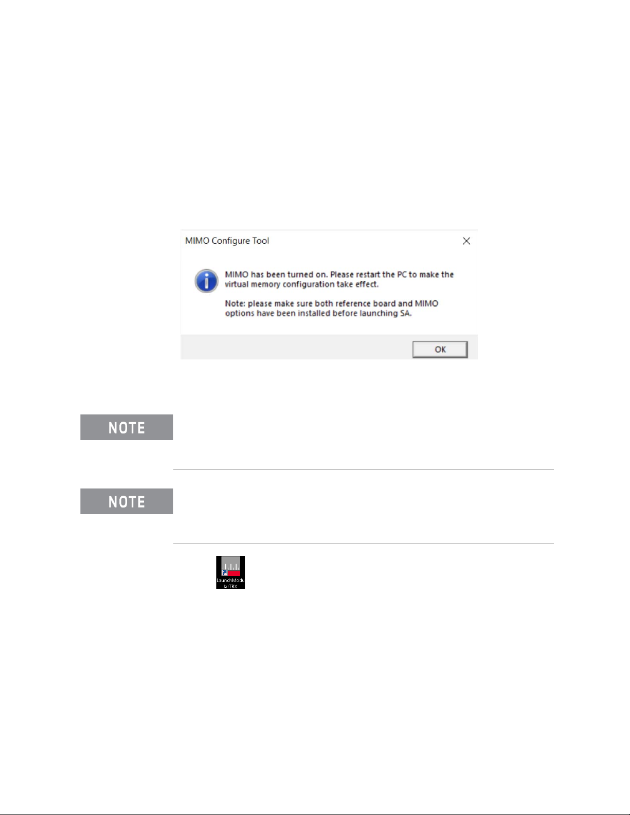
1. Double-click MimoTurnOnTool.exe, a window will pop up as below:
Files\Keysight\X-Series\VXT2".
2. Click OK and restart the controller to make the virtual memory configuration
take effect.
If your ModularTRX application is launched in normal mode previously, the
first two steps are required for MIMO measurement. if your ModularTRX
application is launched in MIMO mode previously, please skip the first two
steps and launch the application directly from step 3.
Click Input/Output > RF Source Tab to check the current status of your
ModularTRX application. If the Source Sync sub-menu is accessible, the
application is in MIMO measurement status. If the Source Sync sub-menu is
invalid, the application is in basic mode.
3. Click to start the application launcher. All the installed modules will
be shown as "Idle" status in the launcher window as below. Select all the
needed modules for MIMO measurement in the launcher. Click Run
Selected and the TRX applications of all the selected modules will be
launched immediately.
MIMO Measurement Guide 15
Page 16

MIMO Connection and Launch
Launch ModularTRX Application for MIMO Measurement
In this MIMO measurement, 4 TRX applications will be launched in your
controller.
The M9300A reference will be enabled automatically during the TRX
launching process for MIMO measurement. Please close the M9300A SFP
(Software Front Panel) program before launching the TRX application for
MIMO measurement.
If a module is already running, Run Selected will be disabled as below.
To locate the needed application window from other similar ones, check the
slot information in the upper-left corner as the figure below.
16 MIMO Measurement Guide
Page 17

MIMO Connection and Launch
Launch ModularTRX Application for MIMO Measurement
Switch to Basic Mode from MIMO Measurement
To disable MIMO feature and switch back to basic mode, please follow the
procedures below.
1. Turn off all the TRX application windows for the modules used in MIMO
measurement.
2. Run "C:\Program Files\Keysight\X-Series\VXT2\MimoTurnOffTool.exe" in
the controller, a window will pop up as below:
3. Click to run the M9300A Soft Front Panel software. Click Connect
and the reference will be available for all the connected modules.
4. Restart the launcher and the TRX application will switch back to the basic
mode.
For the further information about TRX launcher configuration, please refer to
M9410A/M9411A Getting Started Guide for details.
MIMO Measurement Guide 17
Page 18

MIMO Connection and Launch
Launch ModularTRX Application for MIMO Measurement
18 MIMO Measurement Guide
Page 19

Keysight M9410A/M9411A VXT PXIe Vector Transceiver
MIMO Measurement Guide
3 Basic Operation
This chapter introduces fundamental front panel operation. If you are familiar
with the basic operations listed as below, you can skip this chapter and go
directly to Chapter 4, “Waveform Operation”, on page 23. For further
operation of ModularTRX application on M9410A/M0411A, refer to the Online
Help or Getting Started Guide
— “Viewing Key Descriptions” on page 20
— “Setting RF Source parameters” on page 20
— “Saving and Recalling States” on page 21
— “Selecting Source Output” on page 21
— “Setting Frequency and Power (Amplitude)” on page 22
19
Page 20

Basic Operation
Viewing Key Descriptions
Viewing Key Descriptions
Table 3-1 Online Help Access
Press the question mark key for comprehensive help information. The online help is
context-sensitive (that is, the question mark key opens to a page that is relevant to
the last key you pressed). Also, while the help screen is open, press any key, and a
page relevant to that key is displayed; the normal key function does not execute.
Press ESC to exit the online help.
Setting RF Source parameters
The source functionality is accessed by selecting Input/Output key as below.
Selecting the Input/Output key opens up a softkeys menu under the RF Source
tab on the right side of the application window. These keys allow complete
configuration of the corresponding tab’s parameters.
20 MIMO Measurement Guide
Page 21

Basic Operation
Saving and Recalling States
Saving and Recalling States
The current state (including both source and analyzer settings) can be saved
and later recalled.
1. Click file icon in the bottom bar, and click Save key to access
the file operation window. Select State in the left side of this window.
2. Choose a register in which to save the state by pressing one of the
Register keys. (A register with no state saved in it is in blank; when you
save a state in it, the register is labeled with the date and time.)
3. Alternatively, you can save the state to a file rather than to a register. Click
the Save To File key in the upper-right corner of the window, and use the
file-save window to chose a name and location for the file.
4. Recall a saved state by clicking Recall key, followed by the State key.
5. Choose a register from which to retrieve a state by Selecting one of the
Register keys.
6. Alternatively, you can retrieve the state from a file rather than from a
register. Click the Recall From File key, and chose a name and location for
the file.
Selecting Source Output
To select the output port for the source, access the Input/Output menu.
1. Click Input/Output, RF Source tab, RF Output Port, RF Output.
2. Select from RF Output, and RFIO HD. If you select RF Output, this means
that the RF Output designated as an output will be used.
MIMO Measurement Guide 21
Page 22

Basic Operation
Setting Frequency and Power (Amplitude)
Setting Frequency and Power (Amplitude)
To set the frequency and power of the source output proceed as follows:
1. Select Input/Output, RF Source, Amplitude, Source Amplitude.
2. Use the numeric keypad to set a value for power. Press the appropriate
units key to complete the entry.
3. Select Frequency.
4. Use the numeric keypad to set a value for frequency. Press the appropriate
units key to complete the entry.
5. Turn the RF Output key to On.
Example: Configuring a 700 MHz, 20 dBm Continuous Wave Output
1. Preset the source by Input/Output, RF Source, Source Preset.
2. Select Input/Output, RF Source, Frequency key. Press 700 on the keypad
and select the MHz key.
3. Click Amplitude key. Press 20 on keypad and select the -dBm key.
4. Turn the RF Output to On.
5. Press Input/Output, RF Output Port, RF Output.
The 700 MHz, 20 dBm CW signal is available at the RF OUTPUT port (to
select the output port see “Selecting Source Output” on page 21).
22 MIMO Measurement Guide
Page 23

Keysight M9410A/M9411A PXIe Vector Transceiver
MIMO Measurement Guide
4 Waveform Operation
Before using this information, you should be familiar with the basic operation of
the transceiver source. If you are not familiar with functions such as setting
power level and frequency, refer to Chapter 3 and familiarize yourself with the
information in that chapter. If you are familiar with the waveform operations
listed as below, you can skip this chapter and go directly to Chapter 5, “Making
MIMO Measurements”, on page 43.
— “Waveform File Basics” on page 24
— “Storing, Loading, and Playing a Waveform Segment” on page 25
— “Saving a Waveform Settings & Parameters” on page 28
— “Using Waveform Markers” on page 31
— “Licensing” on page 34
— “Generate a Waveform File with Signal Studio” on page 40
23
Page 24

Waveform Operation
Waveform File Basics
Waveform File Basics
There are two types of waveform files:
—A segment is a waveform file that you download to the transceiver.
—A sequence is a file you create in the transceiver source that contains
pointers to one or more waveform files. The current M9410A/M9411A
software only supports waveform segment operation and the waveform
sequence operation will be supported in future.
Instrument Memory
The instrument has two types of memory:
— Volatile memory, baseband generator (ARB) media, where waveform files
are played from or edited.
— Non–volatile memory, the controller internal hard disk, where waveform
files are stored.
Dual ARB Player
The dual ARB waveform player enables you to play, rename, delete, store, and
load (external or internal) waveform files. The dual ARB waveform player also
provides markers capability.
24 MIMO Measurement Guide
Page 25

Waveform Operation
Storing, Loading, and Playing a Waveform Segment
Storing, Loading, and Playing a Waveform Segment
The source has two types of waveform storage. The waveforms are stored on
the controller hard disk which is non-volatile storage. In order to play the files
out they must be moved into ARB memory which is volatile storage. ARB
memory is also called “working” media, because before you can play, edit, or
include a waveform file, the waveform file must be loaded into ARB memory.
Loading a Waveform Segment into ARB memory
Waveforms must reside in ARB memory before they can be played, or edited.
Cycling power or rebooting the transceiver deletes the files in ARB memory.
1. Click file icon in the bottom bar, and click Recall key to access
the recall sub-menu.
2. Select Waveform in the left column, and click Recall From File to display
files on the hard disk in C:\NVARB and then, highlight the desired
waveform segment.
3. Press Recall to load this waveform segment from hard disk to ARB
memory.
Or you could double click on the file name of desired waveform segment
to load it to ARB memory directly.
MIMO Measurement Guide 25
Page 26

Waveform Operation
Storing, Loading, and Playing a Waveform Segment
Deleting a Waveform Segment on Internal Disk
Use the following steps to delete a file on the hard disk.
1. Click file icon in the bottom bar, and click Recall key to access
the recall sub-menu.
2. Select Waveform in the left column, and click Recall From File to display
files on the hard disk in C:\NVARB and then, right-click on the file name
which you want to delete. A window named "Delete xxx.wfm" will pop up.
3. Press Delete xxx.wfm to delete the waveform file immediately.
Deleting a Waveform Segment from ARB memory
1. Click file icon in the bottom bar, and click Recall key to access
the recall sub-menu.
2. Select Waveform in the left column, and click Recall From File to display
files on the hard disk in C:\NVARB and then, the waveform segments in
ARB memory is listed in the left column of the window.
3. highlight the desired waveform segment which you want to delete.
4. Press Delete Segment From ARB Memory.
Alternatively, if you want to clear all ARB memory select Delete All From ARB
Memory.
26 MIMO Measurement Guide
Page 27

Waveform Operation
Storing, Loading, and Playing a Waveform Segment
Playing a Waveform Segment
Waveforms must reside in ARB memory before they can be played, or edited.
Please refer to “Loading a Waveform Segment into ARB memory” on page 25
to load a waveform segment into ARB memory before playing this waveform.
Cycling power or rebooting the transceiver deletes the files in ARB memory.
1. Select Input/Output key and RF Source tab.
2. Press Mod ulation Setup, ARB Setup, Select Waveform.
3. Select a waveform from the list in the display.
4. Press OK to execute the waveform.
5. In the Basic Control menu, turn ARB State to On to enable the modulation.
Then the waveform modulates the RF carrier.
6. Configure the RF Output:
Set the RF carrier frequency and amplitude, and turn on the RF output in
Input/Output, RF Source menu.
The waveform segment is now available at the selected RF Output
connector.
MIMO Measurement Guide 27
Page 28

Waveform Operation
Saving a Waveform Settings & Parameters
Saving a Waveform Settings & Parameters
This section describes how to edit and save a file header. When you download
only a waveform file (I/Q data, which the source treats as a waveform
segment), the source automatically generates a file header and a marker file
with the same name as the waveform file. Initially the file header has no source
settings saved to it, and the marker file consists of all zeros. For a given
waveform, you can save source settings and parameters in its file header and
marker settings in its marker file; when you load a stored waveform file into
ARB memory, the file header and marker file settings automatically apply to
the source so that the dual ARB player sets up the same way each time the
waveform file plays.
Some of the current source settings shown in the file header appear as part of
the key labels, and others appear in the dual ARB summary display, shown in
the following example. To view the file header:
1. Select Input/Output key and RF Source tab.
2. Press Mod ulation Setup, ARB Setup keys. Ensure that a waveform has
been selected under the Select Waveform key.
3. Press Header Utilities key in the ARB Setup column. The header
information is shown as below.
Sample Rate The waveform playback rate. This is the ARB sample clock rate, set in the Arb Setup menu.
Runtime Scaling The Runtime scaling value is applied in real–time while the waveform is playing. This setting can be
changed only for files playing in the dual ARB player.
RMS When the modulator attenuation setting is set to Auto, this value is used to calculate the I/Q modulator
attenuation setting to optimize ACPR. Value: 0 to 1.414213562
Marker 1...4 Polarity Marker polarity can be positive or negative.
RF Blank Routing Which marker, if any, implements the Pulse/RF Blanking function when the marker signal is low. When
the marker signal goes high, Pulse/RF Blanking discontinues.
Over Range Protect Indicated whether DAC Over–Range Protection is on (1) or off (0).
Unique Waveform Id 0 = no Id; once an Id is assigned, it cannot be changed.
License Required Indicates whether a license is required to play the waveform.
28 MIMO Measurement Guide
Page 29

Waveform Operation
Saving a Waveform Settings & Parameters
Viewing and Modifying Header Information
1. From ARB memory, select the desired waveform:
a.Select Input/Output key and RF Source tab.
b.Press Modulation Setup, ARB Setup, Select Waveform.
c.In the display, select the desired waveform.
d.Press Select Waveform.
2. Open the Header Utilities menu:
In the ARB Setup menu, select Header Utilities
The Figure below shows the default file header for the desired waveform.
The column with text in gray shows that most of the settings are
Unspecified. Unspecified means that there is no setting saved for that
particular parameter.
The column with text in white shows the current source settings. These are
the settings that are saved to the file header.
If a setting is unspecified in the file header, the source uses its current value for
that setting when you select and play the waveform.
Figure 4-1 Example File Header
3. Save the information in the white text column to the file header:
Press Save Header key.
MIMO Measurement Guide 29
Page 30

Waveform Operation
Saving a Waveform Settings & Parameters
Both the gray and white text column now display the same values; the
gray text column lists the settings saved in the file header.
4. Edit and update settings
a.Set the ARB sample rate to 5 MHz:
Press Sample Rate, 5, MHz.
b.Set waveform runtime scaling to 60%:
Press Run-time Scaling, 60, Enter.
The white text column now reflects the changes to the current
source setup, but gray text column have not changed.
c.Save the current settings to the file header:
Press the Save Header key.
The settings from the white text column now appear in the gray text
column. This saves the new current transceiver settings to the file
header.
If you change any of the settings listed in the file header after you select the
waveform file, the changed setting(s) appear in the file header white text
column and are used instead of the saved header settings. To reapply the
saved header settings, reselect the waveform for playback.
30 MIMO Measurement Guide
Page 31

Waveform Operation
Marker
File
Bit N
Marker
Polarity
Marker N
RF Blank Off On
Marker N
Blanks RF when
Marker is Low
EVENT N
Negative
Positive
Set Marker
On Off
Marker N
ALC Hold Off On
Marker N
Holds ALC when
Marker is Low
When the source encounters an enabled marker (described on page 24), an
auxiliary output signal is generated and routed to the rear panel.
Events 1-4 are available at the TRIGGER 1 connector and at the TRIGGER 2 connector.
RF Blank Only: includes ALC Hold
Using Waveform Markers
Using Waveform Markers
The source provides four waveform markers to mark specific points on a
waveform segment. When the source encounters an enabled marker, an
auxiliary signal is routed to trig 1/2 port. The marker that is routed to the
TRIGGER 2 connector is selected using the Input/Output menu.
You can use the output signal to synchronize another transceiver with the
waveform, or as a trigger signal to start a measurement at a given point on a
waveform.
You can also configure markers to initiate Pulse/RF Blanking.
When you download a waveform file that does not have a marker file
associated with it, the source creates a marker file without any marker points.
The following procedures demonstrate how to use markers while working with
the ARB player. These procedures also discuss two types of points: a marker
point and a sample point. A marker point is a point at which a given marker is
set on a waveform; you can set one or more marker points for each marker. A
sample point is one of the many points that compose a waveform.
This section also provides the following information:
• “Waveform Marker Concepts
• “Viewing a Marker Pulse” on page 32
• “Setting Marker Polarity” on page 33
Waveform Marker Concepts
The source dual ARB provides four waveform markers for use on a waveform
segment. You can set each marker polarity and marker points (on a single
sample point or over a range of sample points). Each marker can also perform
Pulse/RF Blanking.
MIMO Measurement Guide 31
Page 32

Waveform Operation
Using Waveform Markers
Marker Signal Response
The source aligns the marker signals with the I and Q signals at the baseband
generator. However some settings such as amplitude, filters, and so forth
within the RF output path can create delays between the marker TRIGGER 2
output signal and the modulated RF output. When using the marker TRIGGER
2 output signal, observe the signals (marker relative to modulated RF) for any
latency, and if needed, reset the marker point positions, include delay or both.
Marker File Generation
Downloading a waveform file that does not have a marker file associated with it
causes the source to automatically create a marker file, but does not place any
marker points.
Marker Point Edit Requirements
Before you can modify a waveform segment marker points, the segment must
reside in ARB memory (see “Loading a Waveform Segment into ARB memory”
on page 25).
Saving Marker Polarity and Routing Settings
Marker polarity and routing settings remain until you reconfigure them, preset
the source, or cycle power. To ensure that a waveform uses the correct settings
when it is played, set the marker polarities or routing (Pulse/RF Blanking) and
save the information to the file header (page 28).
When you use a waveform that does not have marker routings and polarity settings
stored in the file header, and the previously played waveform used Pulse/RF
Blanking, ensure that you set Pulse/RF Blanking to
result in no RF output or a distorted waveform.
Selecting which Marker to output
To select which one of the four markers is output at the TRIGGER 2 connector:
1. Select Input/Output key and Trigger Ouput tab.
2. Press Trig 2 Out keys.
3. Press Trig 2 Out key, click Source Marker 1, Source Marker 2, Source
Marker 3, or Source Marker 4 key as required to choose which marker to
output.
None. Failure to do so can
Viewing a Marker Pulse
When a waveform plays, you can detect an enabled marker pulse at the Trig 2
connector. This example demonstrates how to view a marker pulse generated
by a waveform segment that has at least one marker point set. The process is
the same for a waveform sequence.
32 MIMO Measurement Guide
Page 33

Waveform Operation
RF OUT
Marker pulse on the TRIGGER 2.
Using Waveform Markers
This example uses a sine waveform segment in the dual ARB Player.
Factory–supplied segments have a marker point on the first sample point for
all four markers.
1. follow the procedure on page 25 to select and load the waveform segment
file you need.
2. In the ARB Setup menu, Set ARB State to On.
3. Connect the instrument source output to the oscilloscope channel 1 input.
4. Connect the instrument TRIG 2 output to the oscilloscope channel 2
input.
When marker 1 is present, the instrument outputs a signal through TRIG
2 as shown in the following example.
Setting Marker Polarity
Setting a negative marker polarity inverts the marker signal.
1. In ARB Setup menu, Click Marker Polarity to choose Negative or Positive.
2. For each marker, set the marker polarity as desired.
—The default marker polarity is positive.
—Each marker polarity is set independently.
See also, “Saving Marker Polarity and Routing Settings” on page 32.
MIMO Measurement Guide 33
Page 34

Licensing
Signal Studio
Waveform Operation
Licensing
You can create your own signal waveforms to output from the transceiver ARB
using a number of methods. One of them is to use Keysight Signal Studio
which is a suite of signal creation software that allows you to create
customized signals for multiple radio standards. You can also create your own
signals using other signal creation software (such as MATLAB or ADS) and
download them to the transceiver hard disk. You can use Signal Studio Toolkit
to process your customized files for use on the transceiver, if necessary. The
instrument also provides a multi-pack licensing solution, a cost-effective
solution that allows you to license individual Signal Studio waveforms rather
than purchase the Signal Studio software.
Note that the Signal Studio files are encrypted waveforms; they are stored on the
hard disk on the transceiver and are moved to the volatile ARB memory for
playout. Other waveforms that you create may not be encrypted.
Signal Studio software allows you to create technology-specific waveforms. It
can be downloaded from the Keysight website at:
www.keysight.com/find/signalstudio
To use Signal Studio waveforms on the transceiver, you can either purchase a
Signal Studio license or use waveform multi-pack licensing (see the next
section). The Signal Studio website allows you to purchase the Signal Studio
license and also provides trial licenses. The Signal Studio license is transceiver
specific and therefore cannot be used on a transceiver other than the one
specified in the purchase agreement. Once you have licensed the required
Signal Studio software package, any waveforms that you create using this
package can be used on the transceiver.
N7631C Signal Studio Pro for 5G NR
Signal Studio Pro for 5G NR software is a flexible signal creation tool to quickly
and easily generate 5G NR signals for component, transmitter, and receiver
test. There are two types of licenses:
— A PC based license for waveform creation and download to a supported
signal generators (N7631APPC)
— An instrument embedded license for waveform creation, downloading and
playback (N7631EMBC)
N7617C Signal Studio for WLAN 802.11
Signal Studio for WLAN 802.11 software supports MIMO testing with up to 8
streams/antennas. Only the instrument embedded license for waveform
creation, downloading and playback is available (N7617EMBC).
For waveform generation in Signal Studio, please refer to “Generate a
Waveform File with Signal Studio” on page 40.
34 MIMO Measurement Guide
Page 35

Waveform Operation
Licensing
Waveform multi-pack licensing
Each license gives you certain number of slots for waveforms. For 45 slots, buy
nine 5-pack licenses. For 500 slots, buy ten 50-pack licenses. For 545 slots,
buy nine 5-pack licenses and ten 50-pack licenses.
Waveform multi-pack licensing (Option 2xx) enables you to create, generate
and permanently license multiple Signal Studio waveforms without the need to
purchase the full Signal Studio license.
A multi-pack license includes a number of license slots which are used to
license waveform segments. The number of license slots varies depending on
the multi-pack license option that has been purchased. When a waveform
segment is licensed, it is assigned to one of the license slots. Waveform
segments licensed with a multi-pack license are perpetual and cannot be
exchanged. Once a waveform is licensed, that license is permanent and cannot
be revoked or replaced.
Signal Studio waveforms can be downloaded to the instrument and placed into
a waveform slot for a 48 hour trial period. This allows you to edit and reuse this
slot for 48 hours. After the 48 hour time period the STATUS of this slot will be
changed to LOCK REQUIRED. This waveform slot now has been consumed and
is no longer available for editing or reuse.
Option 2xx waveform licenses are transceiver specific (i.e. transceiver Host ID /
PCSERNO). If the licensed waveform segment is transferred from one
instrument to another the segment file must be re-licensed on the new
instrument by a multi-pack license on that instrument before it can be played
back.
To license additional waveforms that exceed the number permitted by a
multi-pack option, you must purchase an additional multi-pack option that
you do not already own. For example, if you have Option 221 and need
additional waveforms, you should purchase Option 222. Re-purchasing Option
221 for the same transceiver provides no additional multi-pack licenses.
Waveforms licensed with Options 2xx cannot be exchanged for different
waveforms. Once a waveform is licensed, that license is permanent and
cannot be revoked or replaced.
After licensing a waveform, you can make copies of the waveform using
different file names for use on the same transceiver and even rename the
original file without affecting the waveform license.
You can also use the Option 2xx to license waveforms from N76xxB Signal
Studio software downloaded during its 14–day free trial license. All of the
N76xxB Signal Studio software products provide a 14–day trial period (trial
license). This 14–day trial license lets you download and play back waveforms
during the trial period. These waveforms are denoted by the TRL in the status
message area of the waveform segment catalog. After the trial period expires,
the TRL message is removed but the waveform remains. You can license these
waveforms after the TRL message is gone.
To redeem an additional Option 2xx upgrade, refer to the Entitlement
Certificate that comes with the instrument order.
MIMO Measurement Guide 35
Page 36

Waveform Operation
Licensing
Installing an Option N7650B–22x/25x Waveform 5/50–Pack Licensing
1. Load a Waveform 5–Pack license, Option N7650B–22x/25x, into the
transceiver using License Manager or a USB media. For more information
on loading the Waveform 5/50–Pack License, refer to the
N7650B–22x/25x Entitlement Certificate.
Licensing a Source Waveform File
1. Create the waveform:
a. Download any of the N76xxB Signal Stud io software that interests
you. For downloading N76xxB Signal Studio software, refer to the
N76xxB Entitlement Certificate or trial website.
b. Create and download a waveform to the transceiver using any of the
N76xxB Signal Studio software. Refer to your Signal Studio
software Help. You can add the waveform to a license slot for a
48-hour trial period. During the trial period, the waveform can be
played and replaced any number of times. When the trial time
expires, the slot can no longer be used for playback until the slot is
locked for permanent playback capability. The slot status will
changed from "Remaining Trial Time" to "LOCK REQUIRED".
36 MIMO Measurement Guide
Page 37

Waveform Operation
Licensing
Waveform Licensing Interface
Click file icon in the bottom bar, and click Save key to access the
file type selection menu.
Select Waveform in the left column, and click Recall From File to display files
on the hard disk in C:\NVARB and then, highlight the desired waveform
segment. Press Recall to load this waveform segment from hard disk to ARB
memory.
The selected file name appears in the left column once it is loaded.
Go back to the ARB Setup menu. Click Waveform Utilities, Ad d Waveform,
select the waveform you want to assign to a slot, and press OK.
Figure 4-2 Assigning the waveform to a slot
MIMO Measurement Guide 37
Page 38

Waveform Operation
Licensing
The loaded waveform will be displayed with a status message of "Remaining
Trial Time 48 Hours". Select the desired waveform and press Lock Waveform
In Slot. A popup window asks you to confirm the lock operation; selecting OK
will change the status of the waveform to "LOCKED [date]". This indicates that
you have successfully licensed the waveform permanently.
Figure 4-3 Locking the waveform to the slot
38 MIMO Measurement Guide
Page 39

Waveform Operation
Licensing
Waveform Multi–Pack Licensing Status Messages
The following messages appear in the Waveform Multi-Pack license display in
the Status column. The table below shows the meaning of the entries in the
Status column.
Table 4-1 Waveform Multi–Pack Licensing Status Messages
Status Message Meaning Notes
Remaining Trial
Time 48 Hours
Multi-Pack
Licensed
Multi-Pack
License Not
Required
Other menu functions under Multi–Pack Licenses
— Replace Waveform: This key allows you to replace the waveform in the
selected slot during the 48 hour trial period.
— Clear Waveform from Slot: This key clears the waveform name from a used
slot so that the name can be used in another slot. Note that this does not
make the original waveform slot reusable, it merely makes the waveform
name reusable.
The waveform can be replaced or modified for
the next 48 hours.
This waveform is licensed by Option 2xx.
This status message applies to:
Any free waveforms provided with the
instrument
Any customer created waveform
Any waveforms that have a valid license (e.g.
Trial (TRL) licenses, Advanced Design System
(ADS), etc.).
Once the 48 hour period has
expired, the waveform status
message changes to "LOCK
REQUIRED".
Once a Trial (TRL) license
expires, the waveform
becomes licensable (i.e. the
status message for the trial
waveform becomes "LOCK
REQUIRED") .
MIMO Measurement Guide 39
Page 40

Waveform Operation
Generate a Waveform File with Signal Studio
Generate a Waveform File with Signal Studio
You can create your own signal waveforms to output from the transceiver ARB
using a number of methods. One of them is to use Keysight Signal Studio
which is a suite of signal creation software that allows you to create
customized signals for multiple radio standards. You can also create your own
signals using other signal creation software (such as MATLAB or ADS) and
download them to the transceiver hard disk. You can use Signal Studio Toolkit
to process your customized files for use on the transceiver.
Generate a Waveform File with N7631C Signal Studio for 5G NR
Please follow the procedures below to generate 4 x 4 MIMO waveform files in
N7631C Signal Studio Pro for 5G NR. This software is available at:
www.keysight.com/find/n7631c
1. Click to run the N7631C Signal Studio Pro for 5G
NR software. The software window will pop up.
2. Waveform Setup is highlighted in the left structure column as default.
Change the Total Number of Antenna to 4.
40 MIMO Measurement Guide
Page 41

Waveform Operation
Generate a Waveform File with Signal Studio
3. Click Channel Setup > DL-SCH, change the DMRS port(s) from 0 to 0,1,2,3,
Antenna port(s) generated will be coupled to p0, p1, p2, p3 automatically.
4. Click generate button as below to generate the waveforms.
5. Click File > Export Waveform Data, Select a folder and file name for the
waveform Data.
MIMO Measurement Guide 41
Page 42

Waveform Operation
Generate a Waveform File with Signal Studio
then you will see four waveforms are generated under the folder with that
file name appended with antenna index, copy these 4 waveform files to the
same folder in the controller for further use in 5G NR MIMO measurement.
You can rename those files but keep the suffix as it is.
The WLAN MIMO waveform generation process is similar as this 5G NR’s.
Please follow the similar procedure to generate the WLAN MIMO waveform
files in N7617C Signal Studio for WLAN. The N7617C software is available at:
www.keysight.com/find/n7617c
42 MIMO Measurement Guide
Page 43

Keysight M9410A/M9411A VXT PXIe Vector Transceiver
MIMO Measurement Guide
5 Making MIMO Measurements
Before making a MIMO measurement, you should be familiar with the basic
operation of the M9410A/M9411A transceiver. If you are not familiar with the
related operations, refer to the embedded online help by the question mark
key.
To make a WLAN MIMO measurement, you need set the sources in TRX
application and set the receivers in TRX application or 89600 VSA software.
To make a 5G NR MIMO measurement, you need set the sources in TRX
application and set the receivers in 89600 VSA software.
— “Making a WLAN MIMO measurement in TRX Application” on page 44
— “Making a 5G NR/WLAN MIMO measurement in 89600 VSA” on page 49
43
Page 44

Making MIMO Measurements
Making a WLAN MIMO measurement in TRX Application
Making a WLAN MIMO measurement in TRX Application
Please refer to the sources and analyzers configuration below to make a WLAN
MIMO measurement with M9410A/M9411A. Before the measurement, make
sure all the modules are connected properly and the TRX software is launched
in MIMO mode. For the detailed procedures, please refer to “MIMO Connection
and Launch” on page 13
Sources Configuration
Please refer to the procedures below to complete the sources configuration.
1. Select an application window for master module as your need according to
the slot number in the upper-left corner of the window.
2. Load a proper waveform "xxxx0.wfm". To load a MIMO measurement
waveform files, select the file name with a suffix "0" as a master waveform
file. The waveform files with other suffix are slave waveform files. You do not
need to load the slave waveform files if you turn Sync Settings Switch On in
step 5. But, you need keep all the slave files in the same folder of the
master waveform file. For details on waveform files operation, please refer
to “Waveform Operation” on page 23.
3. Click Input/Output, Set RF Output On, set RF power and Frequency
accordingly as below.
44 MIMO Measurement Guide
Page 45

Making MIMO Measurements
Making a WLAN MIMO measurement in TRX Application
4. Click Source Sync in Input/Output and the sync settings are shown as
below. Select Master in Sync Type. Select 4x4 in Sync Config
5. Click Sync Settings to access the sync settings window. All the installed
modules in chassis will be shown in the slaves list as below. Check all the
needed slave modules in order according to the slot number. turn Sync
Settings Switch On to sync all the settings from the master module to slave
module.
6. Click Sync Start in Source Sync Setup. The master and slave sources will
play the waveform synchronously.
MIMO Measurement Guide 45
Page 46

Making MIMO Measurements
Making a WLAN MIMO measurement in TRX Application
Analyzers Configuration
Please refer to the procedures below to complete the analyzers configuration
for WLAN MIMO measurement.
1. Choose MIMO Modulation Measurement in WLAN Mode. There are 12
views for your measurement need. You can select the desired measurement
view from the list. We select Stream IQ Polar in this measurement. The
descriptions of the 12 views are listed as below.
• Stream IQ Polar: provides a combination view of I/Q measured polar vector
graph, channel and stream numeric results data.
• Burst & Sig Info: provides a summary view on Burst Info and Sig Info.
• EVM vs. Carrier: provides a RMS EVM vs. subcarrier graph.
• EVM vs. Symbol: provides a RMS EVM vs. Symbol graph.
• Channel Matrix: provides the linear average over all subcarriers of the
equalizer channel frequency response for each available channel/stream.
• Stream Results Summary: provides the stream numeric summary results.
• Channel Results Summary: provides the channel numeric summary
results.
• Spectral Flatness: provides the spectral flatness results for all channels.
• Channel Matrix: provides the linear average over all subcarriers of the
Equalizer Channel Frequency Response for each available channel/stream.
46 MIMO Measurement Guide
Page 47

Making MIMO Measurements
Making a WLAN MIMO measurement in TRX Application
• Frequency Response: provides an overlay of all the individual stream(X)
channel(X) frequency response trace data results.
• Equalizer Impulse Response: provides the equalizer impulse response
between the input stream X and input channel X (where X is the selected
stream/channel).
2. Click Meas Setup > Settings > MIMO Type to select 4x4 for master
analyzer, and click Meas Setup > Global > Remote Analyzer Config to set
the slave analyzer parameters as below.
— Set the IP address to 127.0.0.1 as the local address. If you use remote
control, set it to the controller’s IP address.
— Set the SCPI Socket Port according to the socket port in the Slave List on
page 45.
— Click Add Analyzer. The analyzer will be shown in the available analyzer
list.
— Select to highlight the newly added analyzer in the list. Click Verify
Highlighted Analyzer. The analyzer will be verified and the Verified status
will be switched to On.
— Click Select Highlighted Analyzer. The analyzer will be selected and the
Selected status will be switched to On.
.
Clicking Release Highlighted Analyzer will unlock the current selected
analyzer back into local control mode. If the master application switches
into any other mode from WLAN mode, the remote analyzers will be
released automatically.
MIMO Measurement Guide 47
Page 48

Making MIMO Measurements
Making a WLAN MIMO measurement in TRX Application
After the analyzer is selected, the selected TRX application window will
display a message as below to indicate the current sync state. Select all the
slave analyzers accordingly until all the slave analyzers display the same
message as below.
3. Click the highlighted area as the figure below. Select the desired radio
standard from the drop-down menu. The measurement result will be
displayed as below. This Radio Std setting is also accessible by click
Measure Setup > Radio > Radio Std.
The measurement result will be displayed accordingly as the figure above.
For the WLAN MIMO measurement views description, please refer to the
embedded online help in ModularTRX application.
48 MIMO Measurement Guide
Page 49

Making MIMO Measurements
Making a 5G NR/WLAN MIMO measurement in 89600 VSA
Making a 5G NR/WLAN MIMO measurement in 89600 VSA
Please refer to the procedures below to make a 5G NR MIMO/WLAN
measurement in 89600 VSA software with M9410A/M9411A. Before the
measurement, make sure all the modules are connected properly and the TRX
software is launched in MIMO mode. For the detailed procedures, please refer
to “MIMO Connection and Launch” on page 13
Source Configuration in TRX application
Please refer to “Sources Configuration” on page 44 to set the source
parameters in TRX application for 5G NR/WLAN MIMO measurement.
Set M9410A/M9411A in Keysight Connection Expert
M9410A/M9411A supports the TCP/IP connection standards for LAN and
HiSLIP (High-Speed LAN Instrument Protocol) instrument. Please refer to the
procedures below to set the address in Keysight Connection Expert.
1. Click > I/O Config > SCPI > HiSLIP IP Server to get the HiSLIP number
in the ModularTRX application as below. This value will be used to set the
remote name in Keysight Connection Expert.
If your modules are in source sync state already, you could get the HiSLIP
number by running LaunchModularTRX.exe again. Click Show Advanced
Settings and the HiSLIP number is shown as below.
MIMO Measurement Guide 49
Page 50

Making MIMO Measurements
Making a 5G NR/WLAN MIMO measurement in 89600 VSA
2. Run Keysight Connection Expert on the PC that the VSA software will be run
on and click the Add button under the Instruments tab and select LAN
instrument.
3. Click Enter Address tab.
a Set the Hostname or IP Address of the PC that the ModularTRX
application is running on. If Keysight Connection Expert and VSA will be
running on the same PC as the ModularTRX application, use localhost for
the hostname. Otherwise find out the hostname or IP address of the
controller that the ModularTRX application is running on and enter it.
b Set Protocol to HiSlip and set Remote Name to the number you get from
step #1 above.
c Check the box named Allow *IDN Query and click Test This VISA Address
to verify the connection. If the connection is ready, the address will be
shown next to the button.
dClick OK as a terminator for the settings
4. Click Instrument on the tool bar. You will find the module and its TCP/IP
address is TCPIP0::localhost::hislip3::INSTR.
50 MIMO Measurement Guide
Page 51

Making MIMO Measurements
Making a 5G NR/WLAN MIMO measurement in 89600 VSA
5. Repeat the procedures above until all the modules are available in Keysight
Connection Expert. If it is not successful then ensure the ModularTRX
applications are running and troubleshoot till it is successful, otherwise the
VSA software will not be able to connect.
89600 VSA Software Configuration
To perform a 5G NR/WLAN MIMO measurement with M9410A/M9411A
modules, Keysight PathWave Vector Signal Analysis (89600 VSA) software is
needed to analyze the signals.
The VSA software needs to be able to discover the SCPI connection for the
ModularTRX application associated with the TRX module in order to connect to
it. This requires a LAN instrument entry be present in Keysight Connection
Expert that points to the VISA address for the SCPI server of the ModularTRX
application.
Normally this entry will be automatically created when starting the VSA
application from the ModularTRX application if the VSA software is being run
on the controller. But, the entry will only be automatically created for the
specific ModularTRX application that VSA was started from and not for every
ModularTRX application that might be running. Also, it won't be automatically
created if the VSA software is started from a different PC than the controller the
ModularTRX application is running on.
Once the entries are created, the settings will persist. This configuration only
needs to be done when initially setting up a system.
Before running Keysight 89600 VSA software for the first time, please make
sure your M9410A/M9411A module is configured and verified successfully
in Keysight Connection Expert as described in “Set M9410A/M9411A in
Keysight Connection Expert” on page 49. Otherwise the VSA software will
not be able to connect to your modules.
Running VSA Software
If your VSA software is run on your controller, Click the
Mode/Measurement/View tab in the upper left corner of a ModularTRX
applications. both master and slave modules are available to running the VSA
software.
MIMO Measurement Guide 51
Page 52

Making MIMO Measurements
Making a 5G NR/WLAN MIMO measurement in 89600 VSA
Then select the VSA software version to use and click Launch VSA, the VSA
software will be launched immediately.
If the VSA software is run on a different PC than the controller, click
to run the Keysight PathWave 89600 VSA software
on the remote PC. Please make sure all the modules are connected and shown
in Keysight Connection Expert on your remote PC before running the VSA
software.
Configuring VSA Software
If the VSA software does not connect the TRX modules automatically or if a
MIMO configuration will be used then a VSA hardware configuration must be
configured from within the VSA software. Please refer to the procedures below
to configure the VSA software.
1. Select Utilities > Hardware > Configurations menu entry to open the
Hardware Configuration dialog in the VSA software and then click
button to add a new configuration.
2. Create the necessary entries and selections in that dialog to form the
hardware configuration to be used. Add items from the "Possible Logical
Instruments" section in the top left to the Configuration area in the top
right. There should be the same number of entries added in the top right
Configuration area as the number of TRX modules that will be used (one for
52 MIMO Measurement Guide
Page 53

Making MIMO Measurements
Making a 5G NR/WLAN MIMO measurement in 89600 VSA
each module). Then select each one and select which Instrument address
(in the No.2 area at the bottom) to associate with that position in the
configuration.
The address with the lowest hislip number should be picked to associate
with the first entry in the configuration area and the next increasing hislip
number should be picked for each in order after that. Otherwise, the OK
button will be invalid to press and a notice in red will be pop up.
To check the module slot number associated with the hislip number of the
TCP/IP address, please refer to step 1 of “Set M9410A/M9411A in Keysight
Connection Expert” on page 49
.
After the address is set properly, name the configuration and press the OK
button.
MIMO Measurement Guide 53
Page 54

Making MIMO Measurements
Making a 5G NR/WLAN MIMO measurement in 89600 VSA
3. Select the new configuration to be the Current Analyzer Configuration. The
VSA software will connect to the hardware for that new configuration.
4. Once the hardware configuration is selected then the input channels menu
will allow selecting different channel configurations to use from within that
hardware configuration. For multichannel, it is important that the hardware
configuration itself already have multiple modules (logical instruments) as
part of that configuration, because the input channels menu will only show
possible channel configurations for hardware that is part of the currently
selected analyzer configuration.
Click Input > RF > 4 channel to set all 4 modules available for current
measurement.
54 MIMO Measurement Guide
Page 55

Making MIMO Measurements
Making a 5G NR/WLAN MIMO measurement in 89600 VSA
5. There are two RF input ports in M9410A/M9411A: RF Input and RFIO HD.
Click Input > Extension to make sure to select the correct input based on
your hardware connection.
MIMO Measurement Guide 55
Page 56

Making MIMO Measurements
5G NR MIMO
Measurement
WLAN MIMO
Measurement
Making a 5G NR/WLAN MIMO measurement in 89600 VSA
6. Click MeasSetup > Measurement Type > Cellular > 5G NR to set the
current measurement type to 5G NR for 5G NR MIMO measurement or click
MeasSetup > Measurement Type > Wireless Connectivity to select a proper
wireless standard to make a WLAN MIMO measurement.
Or, click MeasSetup > + New Measurement to add a new measurement if
you want to keep your current measurement.
To configure the measurement demod properties, click MeasSetup >
Demod properties to access the current measurement demod pop-up
setting window for the specific demod parameters setting.
56 MIMO Measurement Guide
Page 57

Making MIMO Measurements
Making a 5G NR/WLAN MIMO measurement in 89600 VSA
7. After measurement is selected, the default measurement result views will
be shown in several tabs as below. Right-click on a tab and move to MIMO
sub-menu to select your interested MIMO related test result.
The measurement view is shown as below. You can select and customize
the measurement result views according to your test needs.
MIMO Measurement Guide 57
Page 58

Making MIMO Measurements
Making a 5G NR/WLAN MIMO measurement in 89600 VSA
Use VSA Software Dynamic Help
For further VSA software function descriptions, please click Help > Dynamic
Help as below to refer to Keysight 89600 VSA Software embedded dynamic
help on details.
The dynamic help window is shown as below. The content will keep following
your mouse-click action in VSA software and display the description of current
selected menu/toolbar/tab as below.
58 MIMO Measurement Guide
Page 59

Keysight M9410A/M9411A VXT PXIe Vector Transceiver
MIMO Measurement Guide
6 Troubleshooting
This chapter identifies some checks you can make if the MIMO setup and
measurement with the transceiver is not operating as expected. For
information about other related problems, please refer to the Getting Started
Guide and online help.
— “Troubleshooting” on page 60
—“"Reference Unlock" error after application startup
—“MIMO Features Disabled
— “Licenses” on page 60
— “Contacting Keysight Technologies” on page 61
59
Page 60

Troubleshooting
Troubleshooting
Troubleshooting
"Reference Unlock" error after application startup
When a "Reference Unlock" error message is reported, press Input/Output >
More > Freq Ref In. If Freq Ref In is set to External, please make sure there is
correct reference signal with external Ref Freq setting connected to M9300A
Ref In port.
MIMO Features Disabled
If the MIMO features are disabled in application, please check by the steps as
below.
1. Is option MMO installed on all modules for MIMO measurement within a
2. Is the application running in MIMO mode? Run "C:\Program
chassis?
Files\Keysight\X-Series\VXT2\MimoTurnOnTool.exe" in your controller and
restart all applications to switch the instrument into the MIMO mode.
Licenses
A time–based license stops working
Cannot load a time–based license
3. Is the M9300A reference front panel turned off? If the M9300A reference is
still connected, please turn off the M9300A SFP application.
— The transceiver time or date may have been reset forward causing the
time–based license to expire.
— The transceiver time or date may have been reset backward more than
approximately 25 hours, causing the transceiver to ignore time–based
licenses.
The transceiver time or date may have been reset backward more than
approximately 25 hours, causing the transceiver to ignore time–based licenses.
60 MIMO Measurement Guide
Page 61

Troubleshooting
Contacting Keysight Technologies
Contacting Keysight Technologies
— assistance with test and measurements needs, and information on finding a
local Keysight office:
http://www.Keysight.com/find/assist
— accessories, documentation, or new firmware releases:
www.keysight.com/find/m9410a
If you do not have access to the Internet, please contact your field engineer.
In any correspondence or telephone conversation, refer to the transceiver by its
model number and full serial number. With this information, the Keysight
representative can determine whether your unit is still within its warranty period.
MIMO Measurement Guide 61
Page 62

This information is subject to change
without notice.
© Keysight Technologies 2020
Edition 1, April 2020
M9410-90016
www.keysight.com
 Loading...