

Page 1

Keysight M8290A Optical
Modulation Analyzer and
High-Speed Digitizer Test
Solution
Getting Started
Guide
Page 2

Notices
CAUTION
WARNING
© Keysight Technologies 2017
No part of this manual may be reproduced
in any form or by any means (including
electronic storage and retrieval or translation into a foreign language) without prior
agreement and written consent from
Keysight Technologies as governed by
United States and international copyright
laws.
Manual Part Number
M8290-90A01
Edition
Edition 1.0, November 2017
Printed in Malaysia
Keysight Technologies Deutschland GmbH
Herrenberger Strasse 130,
71034 Böblingen, Germany
Technology Licenses
The hard ware and/or software described in
this document are furnished under a
license and may be used or copied only in
accordance with the terms of such license.
U.S. Government Rights
The Software is “commercial computer
software,” as defined by Federal Acquisition
Regulation (“FAR”) 2.101. Pursuant to FAR
12.212 and 27.405-3 and Department of
Defense FAR Supplement
(“DFARS”) 227.7202, the U.S. government
acquires commercial computer software
under the same terms by which the software is customarily provided to the public.
Accordingly, Keysight provides the Software to U.S. government customers under
its standard commercial license, which is
embodied in its End User License Agreement (EULA), a copy of which can be found
at http://www.keysight.com/find/sweula.
The license set forth in the EULA represents
the exclusive authority by which the U.S.
government may use, modify, distribute, or
disclose the Software. The EULA and the
license set forth therein, does not require
or permit, among other things, that Keysight: (1) Furnish technical information
related to commercial computer software
or commercial computer software documentation that is not customarily provided
to the public; or (2) Relinquish to, or otherwise provide, the government rights in
excess of these rights customarily provided
to the public to use, mod ify, reproduce,
release, perform, display, or d isclose commercial computer software or commercial
computer software documentation. No
additional government requirements
beyond those set forth in the EULA shall
apply, except to the extent that those
terms, rights, or licenses are explicitly
required from all providers of commercial
computer software pursuant to the FAR and
the DFARS and are set forth specifically in
writing elsewhere in the EULA. Keysight
shall be under no obligation to update,
revise or otherwise modify the Software.
With respect to any technical data as
defined by FAR 2.101, pursuant to FAR
12.211 and 27.404.2 and DFARS 227.7102,
the U.S. government acquires no greater
than Limited Rights as defined in FAR
27.401 or DFAR 227.7103-5 (c), as applicable in any technical data.
Warranty
THE MATERIAL CONTAINED IN THIS DOCUMENT IS PROVIDED "AS IS," AND IS SUBJECT TO BEING CHANGED, WITHOUT
NOTICE, IN FUTURE EDITIONS. FURTHER,
TO THE MAXIMUM EXTENT PERMITTED BY
APPLICABLE LAW, KEYSIGHT DISCLAIMS
ALL WARRANTIES, EITHER EXPRESS OR
IMPLIED WITH REGARD TO THIS MANUAL
AND ANY INFORMATION CONTAINED
HEREIN, INCLUDING BUT NOT LIMITED TO
THE IMPLIED WARRANTIES OF MERCHANTABILITY AND FITNESS FOR A PAR-
TICULAR PURPOSE. KEYSIGHT SHALL NOT
BE LIABLE FOR ERRORS OR FOR INCIDENTAL OR CONSEQUENTIAL DAMAGES IN
CONNECTION WITH THE FURNISHING,
USE, OR PERFORMANCE OF THIS DOCUMENT OR ANY INFORMATION CONTAINED
HEREIN. SHOULD KEYSIGHT AND THE
USER HAVE A SEPARATE WRITTEN AGREEMENT WITH WARRANTY TERMS COVERING THE MATERIAL IN THIS DOCUMENT
THAT CONFLICT WITH THESE TERMS, THE
WARRANTY TERMS IN THE SEPARATE
AGREEMENT WILL CONTROL.
Safety Notices
A CAUTION notice denotes a hazard.
It calls attention to an operating procedure, practice, or the like that, if
not correctly performed or adhered
to, could result in damage to the
product or loss of important data. Do
not proceed beyond a CAUTION
notice until the indicated conditions
are fully understood and met.
A WARNING notice denotes a hazard.
It calls attention to an operating procedure, practice, or the like that, if
not correctly performed or adhered
to, could result in personal injury or
death. Do not proceed beyond a
WARNING notice until the indicated
conditions are fully understood and
met.
2 Keysight M8290A Getting Started Guide
Page 3

Safety Summary
General Safety
Precautions
Initial Inspection
General This product is a Safety Class 3 instrument. The protective features of this product may
Environment Conditions
The following general safety precautions must be observed during all phases of operation
of this instrument. Failure to comply with these precautions or with specific warnings
elsewhere in this manual violates safety standards of design, manufacture, and intended
use of the instrument. For safe operation, the general safety precautions for the M9502A
and M9505A AXIe chassis, must be followed.
See: http://www.keysight.com/find/M9505A
Keysight Technologies Inc. assumes no liability for the customer's failure to comply with
these requirements. Before operation, review the instrument and manual for safety
markings and instructions. You must follow these to ensure safe operation and to
maintain the instrument in safe condition.
Inspect the shipping container for damage. If there is damage to the container or
cushioning, keep them until you have checked the contents of the shipment for
completeness and verified the instrument both mechanically and electrically. The
Performance Tests give procedures for checking the operation of the instrument. If the
contents are incomplete, mechanical damage or defect is apparent, or if an instrument
does not pass the operator’s checks, notify the nearest Keysight Technologies
Sales/Service Office.
WARNING To avoid hazardous electrical shock, do not perform electrical tests when
there are signs of shipping damage to any portion of the outer enclosure (covers, panels,
etc.).
be impaired if it is used in a manner not specified in the operation instructions.
This instrument is intended for indoor use in an installation category II, pollution degree 2
environment. It is designed to operate within a temperature range of 5 °C – 35 °C (41 °F –
95 °F) at a maximum relative humidity of 80% and at altitudes of up to 2000 meters.
This module can be stored or shipped at temperatures between -40 °C and +70 °C.
Protect the module from temperature extremes that may cause condensation within it.
Ground the Instrument
Before Applying Power
Keysight M8290A Getting Started Guide 3
To minimize shock hazard, the instrument chassis and cover must be connected to an
electrical protective earth ground. The instrument must be connected to the ac power
mains through a grounded power cable, with the ground wire firmly connected to an
electrical ground (safety ground) at the power outlet. Any interruption of the protective
(grounding) conductor or disconnection of the protective earth terminal will cause a
potential shock hazard that could result in personal injury.
Verify that all safety precautions are taken including those defined for the mainframe.
The power cable inlet of the instrument serves as a device to disconnect from the mains
in case of hazard. The instrument must be positioned so that the operator can easily
access the power cable inlet. When the instrument is rack-mounted, the rack must be
provided with an easily accessible mains switch.
Page 4

Line Power Requirements The Keysight M829xA modules operate when installed in a Keysight AXIe mainframe.
Do Not Operate in an
Explosive Atmosphere
Do Not Remove the
Instrument Cover
Do not operate the instrument in the presence of flammable gases or fumes.
Operating personnel must not remove instrument covers. Component replacement and
internal adjustments must be made only by qualified personnel.
Instruments that appear damaged or defective should be made inoperative and secured
against unintended operation until they can be repaired by qualified service personnel.
4 Keysight M8290A Getting Started Guide
Page 5

General Safety Considerations
CAUTION
WARNING
Intended Use
This instrument is intended to use in an office or laboratory environment, under the
environmental conditions listed in the specifications.
Safety Symbols
The caution sign denotes a hazard. It calls attention to a procedure
which, if not correctly performed or adhered to, could result in damage
to or destruction of the product. Do not proceed beyond a caution sign
until the indicated conditions are fully understood and met.
The warning sign denotes a hazard. It calls attention to a procedure
which, if not correctly performed or adhered to, could resul t in injury or
loss of life. Do not proceed beyond a warning sign until the indicated
conditions are fully understood and met.
Instrument Markings
Table 1 Instrument Markings
Symbol Description
Indicates warning or caution. If you see this symbol on a product, you must refer to the
manuals for specific Warning or Caution information to avoid personal injury or damage
to the product.
The laser radiation symbol. This warning symbol is marked on products which have a
laser output.
The electrostatic discharge symbol. This warning symbol is marked on prod ucts which
have components that can be damaged by an electrostatic discharge.
Keysight M8290A Getting Started Guide 5
Page 6

Symbol Description
Indicates the time period during which no hazardous or toxic substance elements are
expected to leak or deteriorate d uring normal use. Forty years is the expected useful life
of the product.
The C-Tick mark is the certification mark of the Australian
Communications Authority.
The RCM Mark is a compliance mark to the ACMA (Australian Spectrum Management
Agency). This indicates compliance with all Australian EMC regulatory information.
CSA is the Canadian certification mark to demonstrate compliance with the Safety
requirements.
The earthing symbol marks a connection that is connected, through the instrument, to
the earth of the line power.
CE compliance marking to the EU Safety and EMC Directives.
ISM GRP-1A classification according to the international EMC standard.
ICES/NMB-001 compliance marking to the Canad ian EMC standard.
This symbol on all primary and secondary packaging indicates compliance to China
standard GB 18455-2001.
6 Keysight M8290A Getting Started Guide
Page 7

Compliance and Environmental Information
Table 2 Compliance and Environmental Information
Safety Symbol Description
This product complies with WEEE Directive (2002/96/EC) marking requirements.
The affixed label ind icates that you must not discard this electrical/electronic
product in domestic household waste.
Product Category: With reference to the equipment types in WEEE Directive Annex I,
this product is classed as a “Monitoring and Control instrumentation” product.
Do not dispose in domestic household waste.
To return unwanted products, contact your local Keysight office, or see
http://about.keysight.com/en/companyinfo/environment/takeback.shtml for more
information.
Keysight M8290A Getting Started Guide 7
Page 8

8 Keysight M8290A Getting Started Guide
Page 9

Contents
1 Introduction
2 Software Installation
3 Using the Instrument
Safety Summary 3
General Safety Considerations 5
Compliance and Environmental Information 7
Introduction 11
Getting Started 12
Additional Documents 12
Pre-Requisites 14
Downloading the Photonic Application Suite Package Manager 15
M8290A Software Installation 18
Installing the Keysight OMA Software 25
Post Installation Steps 27
How to use the Instrument 29
Adding the M829xA to the Connection Expert 30
Setting up the M829xA in the Keysight OMA Software 32
4 AXle Chassis
ESM Front Panel Connector 37
Setting the Startup Delay for the Embedded Controller 39
Keysight M8290A Getting Started Guide 9
Page 10

Contents
5 M829xA Maintenance
Introduction 43
Initial Safety Information 44
Laser Safety Labels 45
ESD Protection 46
Power and Ventilation Requirements 47
Thermal Protection 47
Battery 47
Cleaning Recommendation 47
6 Specifications
M8292A Modular Optical Modulation Analyzer Specifications 50
M8296A Electrical High-Speed Digitizer Specifications 53
General Characteristics 55
Declaration of Conformity 55
10 Keysight M8290A Getting Started Guide
Page 11

Keysight M8290A Optical Modulation Analyzer and
High-Speed Digitizer Test Solution
Getting Started Guide
1 Introduction
Introduction / 11
Getting Started / 12
Additional Documents / 12
Introduction
The M8290A rack-mountable modular coherent test system for the AXIe
platform is designed to address the 400G speed class in a significantly
narrower form factor and a more attractive price point than today’s
oscilloscope-based solutions for this speed class.
For coherent transmitter and receiver testing, the M8292A compact
optical modulation analyzer and M8296A high speed digitizer fill the gap
between the portable N4392A integrated optical modulation analyzer for
100G and the real-time oscilloscope-based N4391A optical modulation
analyzer supporting speed classes of 400G, 600G and 1 Terabit per
second.
The compact and modular approach makes the M8290A optical
modulation analyzer and high-speed digitizer test solution an ideal system
for coherent transmitter signal qualification for EVM and related
parameters as well as for component characterization like ICR, PMQ or
even fully-assembled CFPx-ACO modules. The modular concept
addresses the needs of development teams, new product introduction
groups and production test engineers looking for affordable test
equipment for 400G. The M8290A modular coherent test solution provides
a combination of compactness, affordability and performance that cannot
be achieved with current oscilloscope-based solutions in this speed class.
Page 12

1 Introduction
In the M8290A system configuration, the M8292A optical modulation
analyzer module (a 2-slot AXIe module) and a 4-channel single-slot
electrical digitizer module are available, both operating at 92 GSa/s
sampling rate.
Getting Started
The M829xA is a modular instrument packaged in the AXIe form factor.
AXIe is an open standard for high-performance modular instrumentation.
Different form factors of AXIe chassis are available: 13-slot, 5-slot and
2-slot AXIe chassis.
The M8290A Coherent Test Solution comprises an M9537A AXIe
embedded controller. This controller can control one or multiple M829xA
and consumes one module slot of the AXIe chassis. The M8290A Coherent
Test Solution comes with all required software pre-installed and
configured at the factory. Therefore, the information given in Chapter 2
and Chapter 3 of this guide is only relevant if the user wishes to reinstall a
software package or change the system configuration.
Login details for the embedded controller:
• Username: M8290a_admin
• Password: admin!123
Additional Documents
Additional documentation can be found at:
• http://www.keysight.com/find/M9514A for 14-slot chassis related
documentation.
• http://www.keysight.com/find/M9505A for 5-slot chassis related
documentation.
• http://www.keysight.com/find/M9502A for 2-slot chassis related
documentation.
• http://www.keysight.com/find/M9537A for embedded AXIe controller
related documentation.
• http://www.keysight.com/find/M8290A for optical modulation analyzer
and high-speed digitizer test solution related documentation
• http://www.keysight.com/find/M8292A for AXIe based modular optical
modulation analyzer related documentation
• http://www.keysight.com/find/M8296A for AXIe based electrical
high-speed digitizer related documentation
12 Keysight M8290A Getting Started Guide
Page 13

Keysight M8290A Optical Modulation Analyzer and
High-Speed Digitizer Test Solution
Getting Started Guide
2 Software Installation
Pre-Requisites / 14
Downloading the Photonic Application Suite Package Manager / 15
M8290A Software Installation / 18
Installing the Keysight OMA Software / 25
Post Installation Steps / 27
The M8290A coherent test solution uses a layered software architecture,
which is illustrated below, that requires multiple software packages to be
installed. This chapter explains how to install and configure these
packages. However, in general, they are pre-installed at the factory.
Therefore, the installation process described here only needs to be
completed if the user wishes to reconfigure the system.
Page 14

2 Software Installation
Pre-Requisites
The following are the pre-requisites for installing the Keysight M8290A
software:
• The supported operating systems are:
• Windows 10 (32 bit or 64 bit)
• Windows 8.1 (32 bit or 64 bit)
• Windows 8 (32 bit or 64 bit)
• Windows 7 (32 bit or 64 bit)
• Ensure that you have Keysight IO Libraries Suite Version 17.3 or higher
installed on your system. The Keysight IO Libraries Suite can be found
at http://www.keysight.com/find/iosuite.
14 Keysight M8290A Getting Started Guide
Page 15

NOTE
Even if a non-Keysight I/O library is already installed on your PC, it is still
necessary to install the Keysight I/O library. The Keysight I/O library will
install as “secondary” I/O library in this case. This use case is fully
supported.
Downloading the Photonic Application Suite Package Manager
The Photonic Application Suite (PAS) Package Manager is required to
select and download software packages for proper operation of the OMA.
Skip this section if the PAS Package Manager is already present on the
system.
1 Visit the PAS Package Manager web page at
www.keysight.com/find/photonic-sw, select the Current Version tab,
and click on the Download button to start the download process.
Software Installation 2
Keysight M8290A Getting Started Guide 15
Page 16

2 Software Installation
2Click on the Open button to open the zip file.
3 Unzip the file and double-click on the executable file to run the PAS
Package Manager.
16 Keysight M8290A Getting Started Guide
Page 17

Software Installation 2
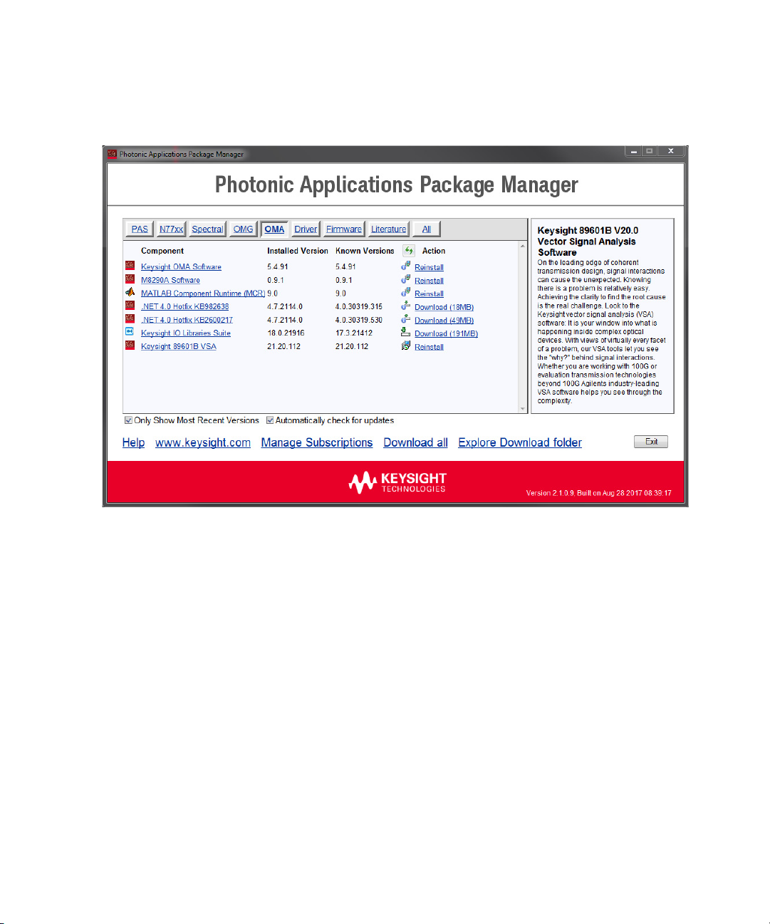
4 Start the PAS Package Manager as administrator and select the OMA
tab to see all possible OMA packages.
Keysight M8290A Getting Started Guide 17
Page 18

2 Software Installation
M8290A Software Installation
Follow the steps below to install the Keysight M8290A software on your
system:
1 Start the PAS Package Manager as administrator, if it is not already
open and select the OMA tab to see all possible OMA packages.
2 Select the “M8290A Software”.
3Click on the Download link.
4 Continue following the installation instructions. The installer will first
check for and list some pre-requisites. Click Install to install them. If
the embedded controller requests you to reboot, please do so
immediately.
18 Keysight M8290A Getting Started Guide
Page 19

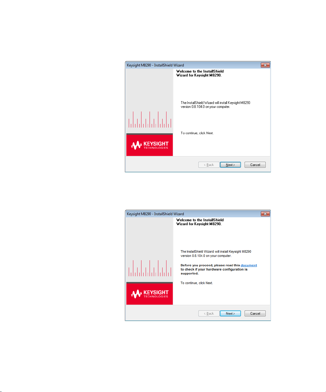
Software Installation 2
5 The Keysight M8290A Setup will prepare the InstallShield Wizard for
the installation process. The following screen will appear.
Keysight M8290A Getting Started Guide 19
Page 20
2 Software Installation
6Click Next. The following screen will appear:
20 Keysight M8290A Getting Started Guide
Page 21

Software Installation 2
7Click Next to proceed to the license agreements.
8 Accept the terms of ‘Keysight Software End-User License Agreement’
and click Next. The following screen will appear:
9 Select Yes if you want to read the post-installation instructions and
click Next. The following screen will appear:
Keysight M8290A Getting Started Guide 21
Page 22

2 Software Installation
10 Select a setup type of either Complete or Custom. If you select
Complete, the M8290A documentation will be installed along with the
M8290A software and a shortcut to the PAS Package Manager will be
added to the Start menu. If you select Custom instead, you can specify
which of the optional features to install.
11 Click Next. The following screen will appear:
22 Keysight M8290A Getting Started Guide
Page 23

Software Installation 2
12 Click Install to begin the software installation. The Setup Wizard
will now install the M8290A software.
Keysight M8290A Getting Started Guide 23
Page 24

2 Software Installation
13 The following screen will appear once the Keysight M8290A software is
successfully installed on your system.
24 Keysight M8290A Getting Started Guide
14 Click Finish to restart your system. This completes the Keysight
M8290A software installation.
Page 25

Installing the Keysight OMA Software
1 Start the PAS Package Manager as administrator, if it is not already
open and select the OMA tab to see all possible OMA packages.
Software Installation 2
2 Select the “Keysight OMA Software”.
3Click on the Download link.
4 Continue following the installation instructions and always select the
default settings. The PAS Package Manager will install additional
drivers and software required to install the OMA software. During the
OMA installation, select M8290A Hardware as setup type. You may
postpone all system restarts until the installation has been completed.
5 When the installation has been completed, verify that the PAS
Package Manager lists all installed components with an “Installed
Version”. If any of them is not listed, please launch the installation of
the missing package again.
Keysight M8290A Getting Started Guide 25
Page 26
2 Software Installation
26 Keysight M8290A Getting Started Guide
Page 27

Post Installation Steps
NOTE
NOTE
Software Installation 2
Follow the post installation steps as shown below:
1 Shut down the embedded controller.
2 Reboot the AXIe chassis.
3 The embedded controller should automatically recognize all available
M829xA modules. You may check this in the device manager; e.g. via
Start > Control Panel > Device Manager, or right-click Computer >
Manage > Device Manager.
The instruments should be visible in the device tree as Keysight
Technologies Modular Devices > M8296A or M8292A respectively.
4 Check if all installed M829xA modules are visible in the Connection
Expert. The connection expert can be opened by clicking its icon in the
system tray.
If something went wrong and any of the instruments does not appear
in the PXI section, it may be necessary to reboot the embedded
controller once more.
To successfully connect the M829xA to the PC, the post installation
steps mentioned above must be strictly followed.
Reboot your PC immediately, if requested to do so.
Keysight M8290A Getting Started Guide 27
Page 28

Page 29

Keysight M8290A Optical Modulation Analyzer and
NOTE
NOTE
High-Speed Digitizer Test Solution
Getting Started Guide
3 Using the Instrument
How to use the Instrument / 29
Adding the M829xA to the Connection Expert / 30
Setting up the M829xA in the Keysight OMA Software / 32
How to use the Instrument
In order to use the instrument:
1 Turn on the AXIe chassis.
2 Start a separate instance of the M8290A Software
(Start > All Programs > Keysight M8290 > Keysight M8290 Software)
for each M829xA module installed in the system. The user interface will
display the VISA resource details required to set up the instrument in
the Connection Expert.
3 Add the M829xA to the Connection Expert as described in section
Adding the M829xA to the Connection Expert on page 30. This step is
required to access the instrument from the Keysight OMA software.
4 Start the Keysight OMA software and set up the instrument connection
as described in the section Setting up the M829xA in the Keysight OMA
Software on page 32.
To show in the Keysight OMA Software, the module must have been
added to the Connection Expert as a LAN instrument. Socket connections
are not supported.
Always close the M8290A Software and shut down the embedded
controller prior to switching off the AXIe chassis.
Page 30

3 Using the Instrument
Adding the M829xA to the Connection Expert
A standard M8290A system is pre-configured at the factory. This section
shows how to modify the factory configuration or to configure a
stand-alone module.
1Open the Connection Expert by clicking its icon ( ) in the system
tray and selecting the corresponding item from the context menu.
2Click on the Add ( ) button in the “My Instruments” section and
select LAN instrument from the drop-down list.
3 Go to the ‘Enter Address’ tab.
4 Enter the hostname or the IP address of the embedded controller
running the M8290A software. Then set the Protocol to HiSlip and
enter the remote name as displayed on the M8290A Software user
interface.
30 Keysight M8290A Getting Started Guide
Page 31

Using the Instrument 3
5Hit the OK button. You should now be able to view the instrument
details within the Connection Expert as indicated below.
6 Verify that the instrument details shown in the Connection Expert are
correct and that the instrument is listed with a green check mark in the
“My Instruments” section. If so, the instrument is ready to be
connected to the Keysight OMA Software as described in the following
section.
Keysight M8290A Getting Started Guide 31
Page 32

3 Using the Instrument
Setting up the M829xA in the Keysight OMA Software
A standard M8290A system is pre-configured at the factory. This section
shows how to modify the factory configuration or to configure a
stand-alone module.
1 In the Keysight 89600 VSA Software interface, select Utilities >
Hardware > Discovered Instruments to view a list of all available
instruments. A screen similar to the following is displayed.
However, if your module is not listed, please add it to the Connection
Expert as described in section Adding the M829xA to the Connection
Expert on page 30 and hit the refresh button ( ).
2Switch to the Configurations tab and click on the plus ( ) button.
32 Keysight M8290A Getting Started Guide
Page 33
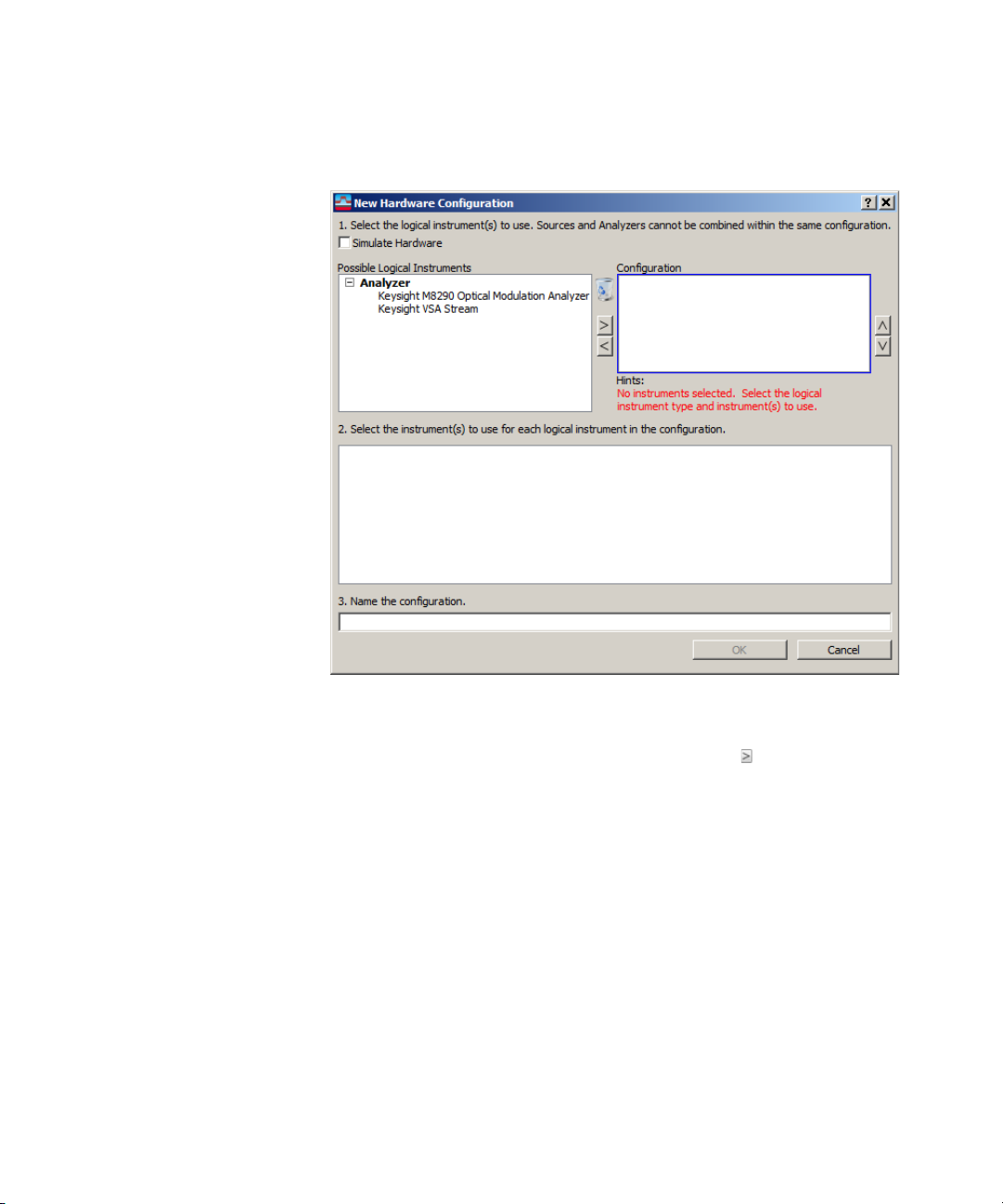
Using the Instrument 3
3From the Possible Logical Instruments list, select Keysight M8290
Optical Modulation Analyzer then click on the button to add it to
the Configuration list.
Keysight M8290A Getting Started Guide 33
Page 34
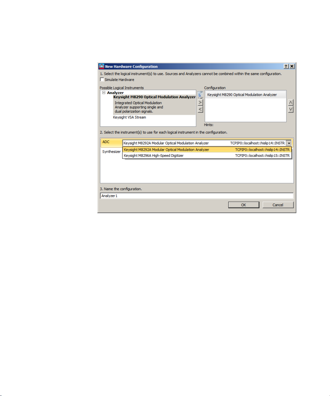
3 Using the Instrument
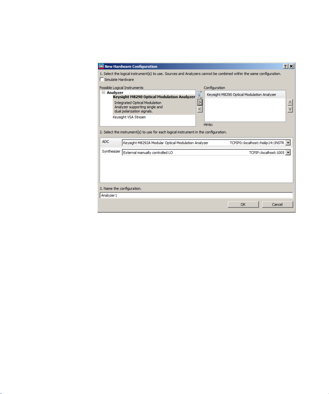
4 In the ADC selection, click on the down arrow and select the desired
instrument.
34 Keysight M8290A Getting Started Guide
Page 35
Using the Instrument 3
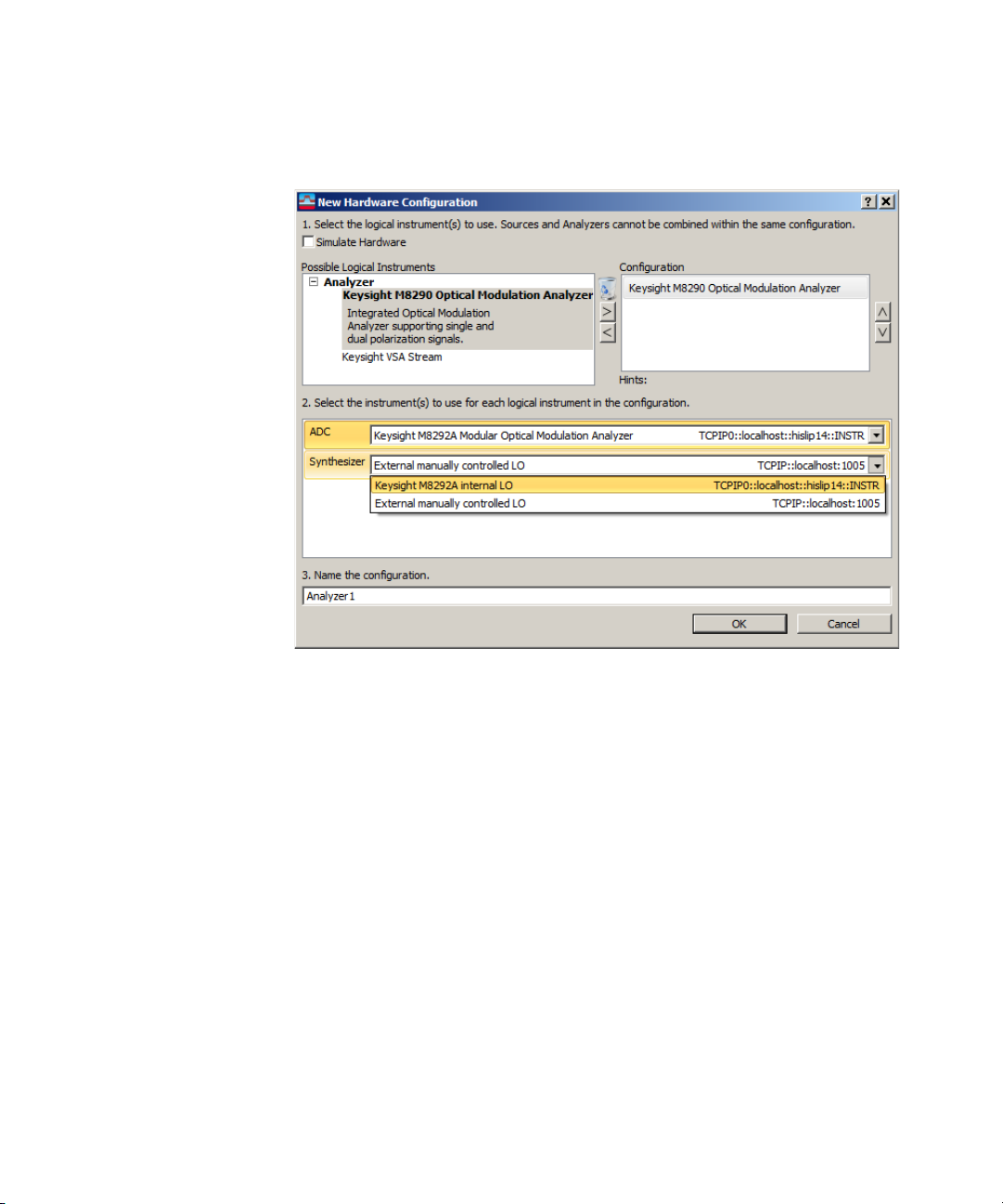
5In the Synthesizer selection, click on the down arrow and select the LO
configuration (internal or external LO). With the M8296A only an
external manually controlled LO is supported. This setting can also be
used if the test setup does not actually include an LO.
Keysight M8290A Getting Started Guide 35
Page 36
3 Using the Instrument
6 In the name field, enter the desired name for this configuration then
click on the OK button.
7 Repeat this procedure to add more configurations.
36 Keysight M8290A Getting Started Guide
Page 37

Keysight M8290A Optical Modulation Analyzer and
High-Speed Digitizer Test Solution
Getting Started Guide
4 AXle Chassis
ESM Front Panel Connector / 37
Setting the Startup Delay for the Embedded Controller / 39
This chapter describes the usage of the AXIe chassis in combination with
the M829xA.
The detailed documentation for the AXIe chassis can be found at:
• http://www.keysight.com/find/M9514A for 14-slot chassis
• http://www.keysight.com/find/M9505A for 5-slot chassis
• http://www.keysight.com/find/M9502A for 2-slot chassis
ESM Front Panel Connector
The ESM Front Panel Connector is shown in the figure below:
Page 38

4 AXle Chassis
1 PCle Connects a host PC to the chassis via PCle.
2 USB Connects a host PC to the chassis via
3 Multiframe Input Synchronizes timing signals with multiple
4 Multiframe Output
5 Trigger In External Trigger connections.
6 Trigger Out
7 Clock In External clock connections.
8 Clock Out
9 LAN Connects the host PC to the chassis, via
10 Status Light Indicates the chassis status.
USB 2.0. The USB 2.0 port is only available
for AXIe chassis with option -U20. Using
USB to connect to the M8290A is not
supported.
daisy-chained chassis.
The Trigger In of the AXIe ESM cannot be
used to trigger the M829xA.
The Trigger Out of the AXIe ESM cannot be
controlled by the M829xA.
10/100/1000 Ethernet.
In particular, the LAN connector is used for
ESM configuration, but NOT to communicate
to the M829xA.
38 Keysight M8290A Getting Started Guide
Page 39

Setting the Startup Delay for the Embedded Controller
For the PCIe connection between the embedded controller and the
M829xA module to work properly, the AXIe modules must boot in a certain
order. To assure that this order is maintained at all times, a startup delay
needs to be configured on the AXIe chassis’ system module. All M8290A
systems are pre-configured accordingly at the factory. However, if a
different AXIe chassis is used with any M829xA module, it may be
necessary to set the startup delay manually. To do this, please complete
the process described below.
1 On the embedded controller, go to the AXIe chassis' web interface (e.g.
by typing “169.254.1.0” into the address bar of a web browser):
AXle Chassis 4
Keysight M8290A Getting Started Guide 39
Page 40
4 AXle Chassis
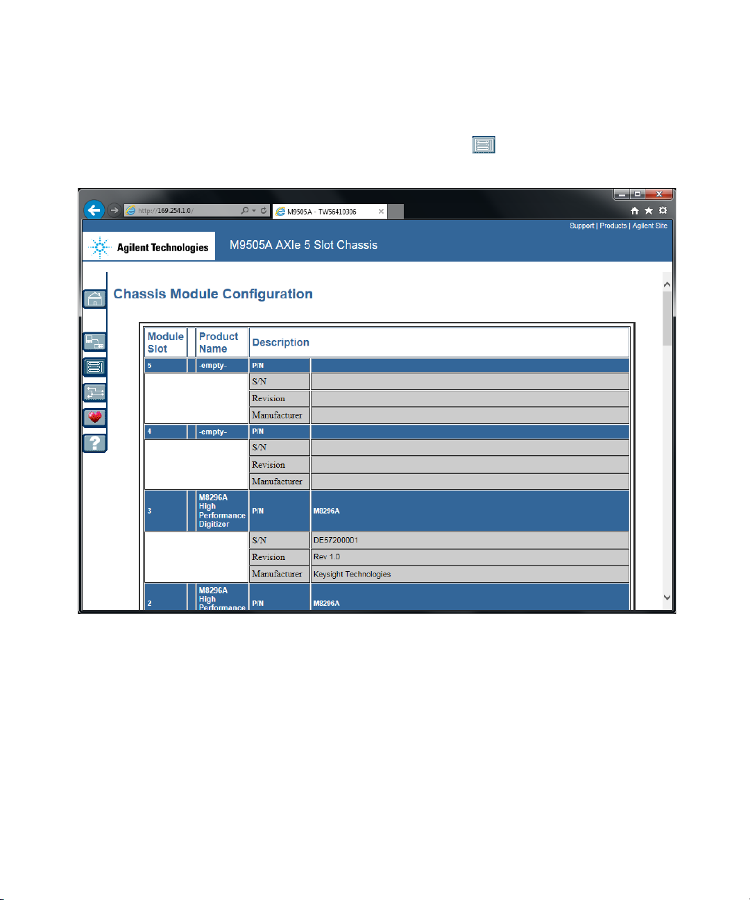
2Click on the “Modules” button ( ) on the left side:
40 Keysight M8290A Getting Started Guide
Page 41

AXle Chassis 4
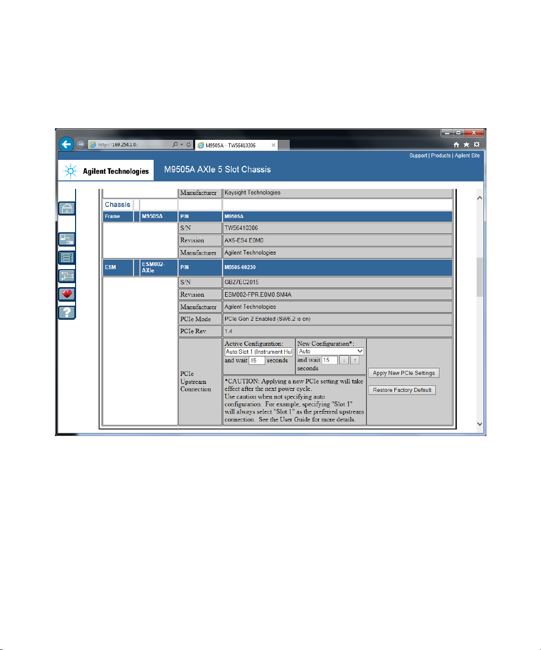
3 Browse to the bottom of the “Chassis Module Configuration” box:
4If the “Active Configuration” shows a wait time below 15 seconds,
select “Auto” in the “New Configuration” list and enter 15 seconds as
the wait time. Then press “Apply New PCIe Settings”.
Keysight M8290A Getting Started Guide 41
Page 42
4 AXle Chassis
5 Shutdown the embedded controller and power cycle the AXIe chassis.
This setting is now shown as the “Active Configuration”:
42 Keysight M8290A Getting Started Guide
Page 43

Keysight M8290A Optical Modulation Analyzer and
High-Speed Digitizer Test Solution
Getting Started Guide
5 M829xA Maintenance
Introduction / 43
Initial Safety Information / 44
ESD Protection / 46
Power and Ventilation Requirements / 47
Thermal Protection / 47
Battery / 47
Cleaning Recommendation / 47
Introduction
This chapter explains how to install and maintain the M829xA. It covers the
following topics:
• Laser Safety
• ESD Protection
• Power & Ventilation Requirements
• Thermal Protection
• Battery
• Operating Environment
• Cleaning Recommendation
Page 44

5 M829xA Maintenance
Initial Safety Information
The laser sources classified by this guide are classified as Class 1M
according to IEC 60825-1 (2014).
All laser sources comply with 21 CFR 1040.10 except for deviations
pursuant to Laser Notice No. 50, dated 2007-June-24.
Table 3 Initial Safety Information
M8292A Options
Max. CW output power
Beam waist diameter < 10 µm -
Numerical aperture 0.1 -
Laser class according to IEC 60825-1 (2014) Class 1M Class 1
Max. permissible CW output power
* Max. CW output power is defined as the highest possible optical CW power that the laser
source can produce at its output.
† Max. permissible CW output power is defined as the highest optical power that is
permitted within the appropriate IEC laser class.
*
†
C92+800
< 100 mW - (internal Laser only)
163 mW 10 mW
Options
C92
44 Keysight M8290A Getting Started Guide
Page 45
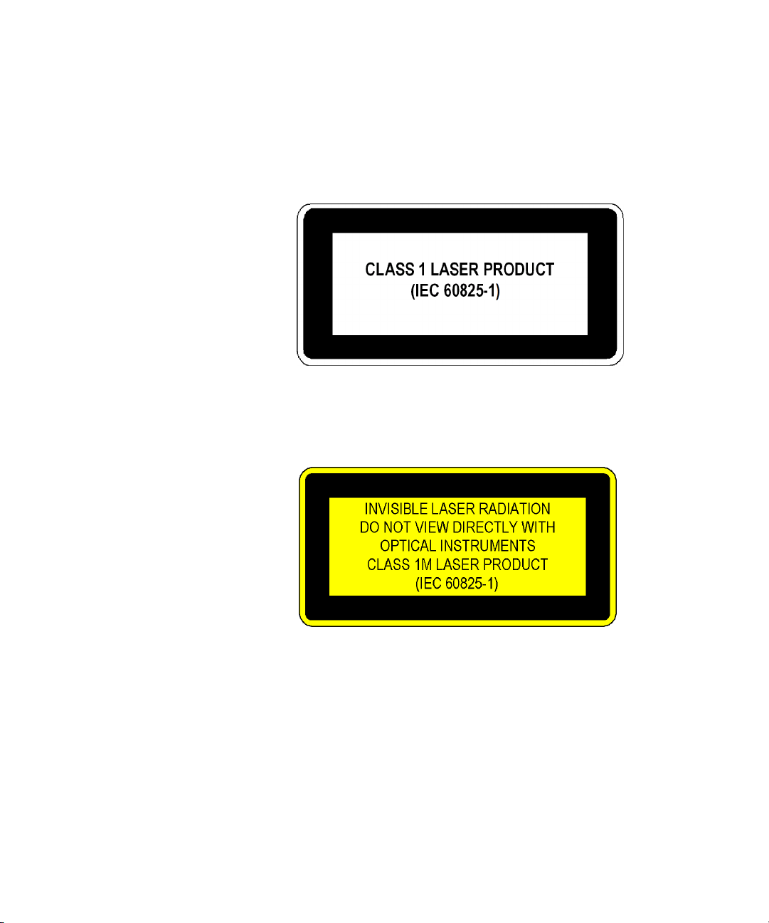
Laser Safety Labels
Laser Class 1 Label
Laser Class 1M Label
M829xA Maintenance 5
A sheet of laser safety labels is included. In order to meet the requirements
of IEC 60825-1 we recommend that you stick the laser safety labels, in
your language, onto a suitable location on the outside of the instrument
where they are clearly visible to anyone using the instrument.
Keysight M8290A Getting Started Guide 45
Page 46

5 M829xA Maintenance
WARNING
CAUTION
CAUTION
Please pay attention to the following laser safety warnings:
• Under no circumstances look into the end of an optical cable attached
to the optical output when the device is operational. The laser
radiation can seriously damage your eyesight.
• Do not enable the laser when there is no fiber attached to the optical
output connector.
• The laser is enabled by the software. The laser is on when the green
LED above the LO Output connector is lit.
• The use of the instruments, such as microscopes or spectacles, with
this product will increase the hazard to your eyes.
• The laser module has built-in safety circuitry which will disable the
optical output in the case of a fault condition.
• Refer servicing only to qualified and authorized personnel.
ESD Protection
All the connectors are very sensitive to electrostatic discharge (ESD).
When you connect a device or cable that is not fully discharged to these
connectors, you risk damage to the instrument and expensive instrument
repairs.
Electrostatic discharge (ESD) can damage the circuits of the M829xA.
Avoid applying static discharges to the front-panel connectors. Before
connecting any coaxial cable to the connectors, momentarily short the
center and outer conductors of the cable together. Avoid touching the
front-panel connectors without first touching the frame of the
instrument. Be sure the instrument and all connected devices (DUT, etc.)
are properly earth-grounded (to a common ground) to prevent buildup of
static charge and electrical over-stress.
46 Keysight M8290A Getting Started Guide
Page 47

Power and Ventilation Requirements
WARNING
For power and ventilation requirements, refer to:
• http://www.keysight.com/find/M9514A for 14-slot chassis related
documentation.
• http://www.keysight.com/find/M9505A for 5-slot chassis related
documentation.
• http://www.keysight.com/find/M9502A for 2-slot chassis related
documentation.
Thermal Protection
Overheating Detection
The instrument monitors its internal temperature. If the temperature
exceeds approximately 80°C the power supply is switched off. The
instrument will not turn on automatically if the temperature is decreasing
again.
Fan Failure
M829xA Maintenance 5
If a fan is broken or prevented from operating by a blockage the
temperature will increase. When the temperature exceeds approximately
80°C the overheating detection switches off the instrument for safety
reasons. For reliability, it is recommended to send instruments with broken
or defective fans immediately to Keysight Service for repair.
Battery
The M829xA does not have a battery.
Cleaning Recommendation
To prevent electrical shock, disconnect the instrument from mains
before cleaning. Use a dry cloth or one slightly dampened with water to
clean external case parts. Do not attempt to clean internally.
Keysight M8290A Getting Started Guide 47
Page 48

Page 49

Keysight M8290A Optical Modulation Analyzer and
High-Speed Digitizer Test Solution
Getting Started Guide
6 Specifications
M8292A Modular Optical Modulation Analyzer Specifications / 50
M8296A Electrical High-Speed Digitizer Specifications / 53
General Characteristics / 55
Declaration of Conformity / 55
Page 50

6 Specifications
M8292A Modular Optical Modulation Analyzer Specifications
Table 4 M8292A Modular Optical Modulation Analyzer specifications
M8292A Modul ar optical modulation analyzer Typical values
Maximum detectable symbol rate 74 Gbaud
Sample rate range 83 to 92 GSa/s
Maximum record length per channel 512 kSa
ADC resolution 8 bit
Operating frequency range
Analog bandwid th, uncorrected 37 GHz (3 dB)
4
1
1 MHz to 40 GHz
Optical wavelength operating range 1527.60 to 1570.01 nm
(196.25 to 190.95 THz)
Average input power monitor accuracy ±0.4 dB
Optical phase angle of I-Q mixer after correction 90° ±0.5°
Relative skew after correction < ±1 ps
Image suppression
5
> 30 dB
Error vector magnitude noise floor < 2.4% EVM rms at 2.5 GHz freq. offset
< 3.5% EVM rms at 10 GHz freq. offset
2
Sensitivity
–20 dBm
–14 dBm (with Option 800)
Internal local oscillator (built-in)
Wavelength settling time < 30 s
Wavelength uncertainty ±4.5 pm (±560 MHz), guaranteed
±2.5 pm (±310 MHz), typical
Sidemode Suppression Ratio (SMSR) ≥50 dB
Relative Intensity Noise (RIN)
3
–145 dB/Hz (10 MHz to 40 GHz)
5
6
50 Keysight M8290A Getting Started Guide
Page 51

Specifications 6
External local oscillator input and output (Option 800)
LO input wavelength range 1527.60 to 1570.01 nm
LO input power range –3 dBm to +17 dBm
LO output power > +9 dBm
1 128 samples are unavailable, resulting in 511872 samples per channel effectively
available.
2 Valid at EVM = 32.5% for 32 GBaud DP-QPSK corresponding to raw BER = 1E-3,
boost mode off.
3 At maximum laser power.
4 Adjusted baseband frequency range available for signal analysis.
5 Valid at the following reference conditions
• Sampling rate 92 GSa/s
• Optical continuous wave signal at optical input port
• Signal power > 0 dBm
• Optical frequency is offset by 2.5 GHz from local oscillator frequency
• Vector analyzer I-Q spectrum span set to 12.5 GHz
• QPSK demodulation
• 10 Gbaud symbol rate
• PolStokesAlign set to “Single Polarization”
• KFPhaseTrack with carrier phase variance set to 1E-4
• Result length set to 500 symbols
• Raised cosine fil ter selected as reference filter
• 25° C ±5 K environmental temperature
6 Valid at reference conditions as stated above, except for:
• Optical frequency is offset by 10 GHz from local oscillator frequency
• Vector analyzer I-Q spectrum span set to 50 GHz
• 40 Gbaud symbol rate
Table 5 M8292A Modular Optical Modulation Analyzer specifications (Continued)
Trigger input Typical values
Input range –4 V to +4 V
Threshold –4 V to +4 V
Range 10 mV
Resolution 100 mV
Keysight M8290A Getting Started Guide 51
Page 52

6 Specifications
Sensitivity 1 MHz to 40 GHz
Polarity Selectable: positive, negative, either edge
Timing uncertainty ≤8 ns
Reference clock input
Input frequency range 10 MHz to 17 GHz
Amplitude range 500 mV
pp
to 2 V
Impedance 50 Ohm (nominal)
Connector type SMA (female)
Reference clock output
Frequency with respect to sample rate fSa / 512
Amplitude 0.9 Vpp (nominal)
Impedance 50 Ohm (nominal)
Connector SMA (female)
Table 6 M8292A maximum ratings
Maximum ratings
Maximum signal input power +14.5 dBm
Signal input damage level +15 dBm
External LO input power
Maximum +17 dBm
Damage level +18 dBm
pp
Reference clock input damage level 3 V
pp
52 Keysight M8290A Getting Started Guide
Page 53

M8296A Electrical High-Speed Digitizer Specifications
Table 7 M8296A Electrical High-Speed Digitizer Specifications
M8296A Electrical high-speed digitizer Typical values
Maximum detectable symbol rate 74 GBaud
Sample rate range 83 to 92 GSa/s
Maximum record length per channel 512 kSa
ADC resolution 8 bit
Operating frequency range
Analog bandwid th, uncorrected 37 GHz (3 dB), guaranteed
Skew between different input channels < ±250 ps
Skew between normal and complement < ±1 ps
2
Specifications 6
1
50 kHz to 42 GHz
3
Input amplitude ranges 150 mV
Input impedance 50 Ohm (nominal)
Number of input channels 4
Trigger input
Input range –4 V to +4 V
Threshold
Range –4 V to +4 V
Resolution 10 mV
Sensitivity 100 mV
Polarity Selectable: positive, negative, either edge
Timing uncertainty ≤ 8 ns
Keysight M8290A Getting Started Guide 53
300 mV
500 mV
800 mV
pp,diff
pp,diff
pp,diff
pp,diff
Page 54

6 Specifications
Reference clock input
Input frequency range 10 MHz to 17 GHz
Amplitude range 500 mVpp to 2 V
Impedance 50 Ohm (nominal)
Connector type SMA (female)
Reference clock output
Frequency with respect to sample rate fSa / 512
Amplitude 0.9 Vpp (nominal)
Impedance 50 Ohm (nominal)
Connector SMA (female)
1 128 samples are unavailable, resulting in 511872 samples per channel effectively
available.
2 Adjusted baseband frequency range available for signal analysis.
3 Determined from a 9th order polynomial fit to the measured amplitude response.
pp
Table 8 M8296A maximum ratings
Maximum ratings
Damage level (single ended) 0.9 Vpp / 3 VDC
Damage level 3 V
pp
54 Keysight M8290A Getting Started Guide
Page 55

General Characteristics
Table 9 General characteristics
Specifications 6
M8292A Modular 92 GSa/s
optical modul ation analyzer
Dimensions
(W x H x D)
Weight 3.6 kg 3.3 kg
Storage
temperature range
Operating
temperature range
Humidity 15% to 80% relative humidity, non-condensing
Operating altitude 0 to 2000 m
Power
consumption
Safety designed to IEC61010-1, UL61010, CSA22.2 61010.1 tested
EMC tested to IEC61326-1
Form factor 2-slot AXIe 1-slot AXIe
Warm-up time 30 minutes
Recommended
re-calibration
interval
322.25 mm x 60 mm x 281.5 mm 322.25 mm x 30 mm x 281.5 mm
–40° C to +70° C
+5° C to +35° C
100 W at 92 GSa/s
2 years
M8296A Modular 92 GSa/s
4-channel electrical high-speed
digitizer
Declaration of Conformity
Click the following link to view or download the latest version of DoC:
http://www.keysight.com/go/conformity
Keysight M8290A Getting Started Guide 55
Page 56

This information is subject to
change without notice.
© Keysight Technologies 2017
Edition 1.0, November 2017
www.keysight.com
 Loading...